

Page 1
ORDER NO. CHM0904017CE
Portable Blu-ray Disc Player
Model No.DMP-B15EB
DMP-B15EE
DMP-B15EG
Vol. 1
Colour
(K)...........Black Type
B35
© Panasonic Corporation 2009. Unauthorized copying and distribution is a violation of law.
Page 2

TABLE OF CONTENTS
1 Safety Precaution -------------------------------------------------3
1.1. General Guidelines ----------------------------------------3
1.2. Leakage Current Cold Check ---------------------------3
1.3. Leakage Current Hot Check (See Figure 1.)--------3
2Warning--------------------------------------------------------------4
2.1. Prevention of Electrostatic Discharge (ESD)
to Electrostatically Sensitive (ES) Devices ----------4
2.2. How to Replace the Lithium Battery-------------------5
2.3. Caution for AC Cord(For EB) ---------------------------6
3 Service Navigation------------------------------------------------7
3.1. Introduction --------------------------------------------------7
3.2. General Description About Lead Free Solder
(PbF) ----------------------------------------------------------7
3.3. Important Notice 1:(Other than U.S.A. and
Canadian Market)------------------------------------------7
3.4. Caution for DivX--------------------------------------------8
3.5. Manual for Customer--------------------------------------8
3.6. Static Electricity Protection Measures ----------------9
3.7. Ground for electrostatic breakdown
prevention----------------------------------------------------9
3.8. Handling of Traverse unit (optical pick-up) ----------9
4 Specifications ----------------------------------------------------10
4.1. Accessories------------------------------------------------ 11
4.2. Others (Licenses) ---------------------------------------- 1 1
5 Location of Controls and Components------------------12
6 Service Mode -----------------------------------------------------14
7 Troubleshooting Guide---------------------------------------- 19
7.1. Self-Diagnosis Functions-------------------------------19
8 Service Fixture & Tools --------------------------------------- 21
9 Disassembly and Assembly Instructions---------------22
9.1. Disassembly Flow Chart--------------------------------22
9.2. PCB Location----------------------------------------------23
9.3. Cleaning of the Optical Pick-up-----------------------31
PAGE PAGE
2
Page 3
1 Safety Precaution
1.1. General Guidelines
1. IMPORTANT SAFETY NOTICE
There are special components used in this equipment
which are important for safety. These p art s are marked by
in the Schematic Diagrams, Circuit Board Layout,
Exploded Views and Replacement Parts List. It is essential that these critical parts should be replaced with manufacturer’s specified parts to prevent X-RADIATION,
shock, fire, or other hazards. Do not modify the original
design without permission of manufacturer.
2. An Isolation Transformer should always be used during
the servicing of AC Adaptor whose chassis is not isolated
from the AC power line. Use a transformer of adequate
power rating as this protects the technician from accidents resulting in personal injury from electrical shocks. It
will also protect AC Adaptor from being damaged by accidental shorting that may occur during servicing.
3. When servicing, observe the original lead dress. If a short
circuit is found, replace all parts which have been overheated or damaged by the short circuit.
4. After servicing, see to it that all the protective devices
such as insulation barriers, insulation papers shields are
properly installed.
5. After servicing, make the following leakage current
checks to prevent the customer from being exposed to
shock hazards.
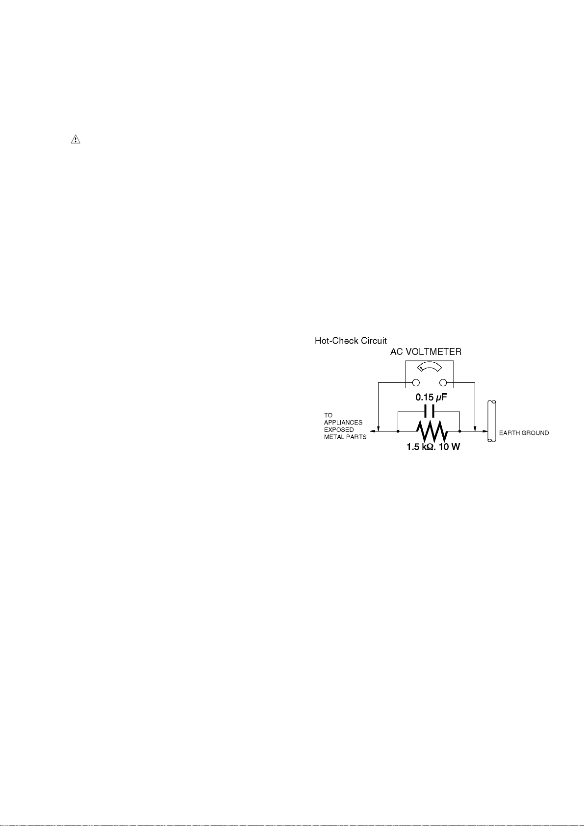
1.3. Leakage Current Hot Check
(See Figure 1.)
1. Plug the AC cord directly into the AC outlet. Do not use
an isolation transformer for this check.
2. Connect a 1.5 kΩ, 10 W resistor, in parallel with a 0.15 μF
capacitor, between each exposed metallic part on the set
and a good earth ground, as shown in Figure 1.
3. Use an AC voltmeter, with 1 kΩ/V or more sensitivity, to
measure the potential across the resistor.
4. Check each exposed metallic part, and measure the voltage at each point.
5. Reverse the AC plug in the AC outlet and repeat each of
the above measurements.
6. The potential at any point should not exceed 0.75 V RMS.
A leakage current tester (Simpson Model 229 or equivalent) may be used to make the hot checks, leakage current must not exceed 1/2 mA. In case a measurement is
outside of the limits specified, there is a possibility of a
shock hazard, and the equipment should be repaired and
rechecked before it is returned to the customer.
1.2. Leakage Current Cold Check
1. Unplug the AC cord and connect a jumper between the
two prongs on the plug.
2. Measure the resistance value, with an ohmmeter,
between the jumpered AC plug and each exposed metallic cabinet part on the equipment such as screwheads,
connectors, control shafts, etc. When the exposed metallic part has a return path to the chassis, the reading
should be between 1 MΩ and 5.2 MΩ. When the exposed
metal does not have a return path to the chassis, the
reading must be infinity.
Figure. 1
3
Page 4

2Warning
2.1. Prevention of Electrostatic Discharge (ESD) to Electrostatically
Sensitive (ES) Devices
Some semiconductor (solid state) devices can be damaged easily by static electricity. Such components commonly are called Electrostatically Sensitive (ES) Devices.
The following techniques should be used to help reduce the incidence of component damage caused by electrostatic discharge
(ESD).
1. Immediately before handling any semiconductor component or semiconductor-equipped assembly, drain off any ESD on your
body by touching a known earth ground. Alternatively, obtain and wear a commercially available discharging ESD wrist strap,
which should be removed for potential shock reasons prior to applying power to the unit under test.
2. After removing an electrical assembly equipped with ES devices, place the assembly on a conductive surface such as aluminum foil, to prevent electrostatic charge buildup or exposure of the assembly.
3. Use only a grounded-tip soldering iron to solder or unsolder ES devices.
4. Use only an antistatic solder removal device. Some solder removal devices not classified as "antistatic (ESD protected)" can
generate electrical charge sufficient to damage ES devices.
5. Do not use freon-propelled chemicals. These can generate electrical charges sufficient to damage ES devices.
6. Do not remove a replacement ES device from its protective package until immediately before you are ready to install it. (Most
replacement ES devices are packaged with leads electrically shorted together by conductive foam, aluminum foil or comparable conductive material).
7. Immediately before removing the protective material from the leads of a replacement ES device, touch the protective material
to the chassis or circuit assembly into which the device will be installed.
CAUTION :
Be sure no power is applied to the chassis or circuit, and observe all other safety precautions.
8. Minimize bodily motions when handling unpackaged replacement ES devices. (Otherwise harmless motion such as the
brushing together of your clothes fabric or the lifting of your foot from a carpeted floor can generate static electricity (ESD) sufficient to damage an ES device).
4
Page 5
2.2. How to Replace the Lithium Battery
This model is using a lithium battery for remote control ass’y.
NOTE:
This Lithium battery is a critical component.
(Type No.: CR2025 Manufactured by Energy Company, Panasonic Corporation.)
It must never be subjected to excessive heat or discharge.
It must therefore only be fitted in requirement designed specifically for its use.
Replacement batteries must be of same type and manufacture.
They must be fitted in the same manner and location as the original battery, with the correct polarity contacts observed.
Do not attempt to re-charge the old battery or re-use it for any other purpose.
It should be disposed of in waste products destined for burial rather than incineration.
5
Page 6
2.3. Caution for AC Cord
(For EB)
2.3.1. Information for Your Safety
IMPORTANT
Your attention is drawn to the fact that recording of prerecorded tapes or discs or other published or broadcast
material may infringe copyright laws.
WARNING
To reduce the risk of fire or sho ck hazard, do not expose
this equipment to rain or moisture.
CAUTION
To reduce the risk of fire or shock hazard and annoying
interference, use the recommended accessories only.
FOR YOUR SAFETY
DO NOT REMOVE THE OUTER COVER
To prevent electric shock, do not remove the cover. No user
serviceable parts inside. Refer servicing to qualified service
personnel.
2.3.2. Caution for AC Mains Lead
For your safety, please read the following text carefully.
This appliance is supplied with a moulded three-pin mains plug
for your safety and convenience.
A 5-ampere fuse is fitted in this plug.
Should the fuse need to be replaced please ensure that the
replacement fuse has a rating of 5 amperes and it is approved
by ASTA or BSI to BS1362
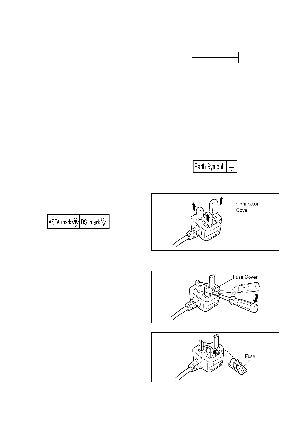
Check for the ASTA mark or the BSI mark on the body of the
fuse.
2.3.2.1. Important
The wires in this mains lead are coloured in accordance with
the following code:
Blue Neutral
Brown Live
As the colours of the wires in the mains lead of this appliance
may not correspond with the coloured markings i dentifying the
terminals in your plug, proceed as follows:
The wire which is coloured BLUE must be connected to the terminal in the plug which is marked with the le tter N or coloured
BLACK.
The wire which is coloured BROWN must be connected to the
terminal in the plug which is marked with the letter L or coloured
RED.
Under no circumstances should either of these wires be connected to the earth terminal of the three pin plug, marked with
the letter E or the Earth Symbol.
2.3.2.2. Before Use
Remove the Connector Cover as follows.
If the plug contains a removable fuse cover you must ensure
that it is refitted when the fuse is replaced.
If you lose the fuse cover, the plug must not be used until a
replacement cover is obtained.
A replacement fuse cover can be purchased from your local
Panasonic Dealer.
If the fitted moulded plug is unsuitable for the socket outlet in
your home then the fuse should be removed and the plug cut
off and disposed of safety.
There is a danger of severe electrical shock if the cut off plug is
inserted into any 13-ampere socket.
If a new plug is to be fitted please observe the wiring code as
shown below.
If in any doubt, please consult a qualified electrician.
2.3.2.3. How to Replace the Fuse
1. Remove the Fuse Cover with a screwdriver.
2. Replace the fuse and attach the Fuse cover.
6
Page 7
3 Service Navigation
3.1. Introduction
This service manual contains technical information, which allow service personnel’s to understand and service this model.
Please place orders using the parts list and not the drawing reference numbers.
If the circuit is changed or modified, the information will be followed by service manual to be controlled with original service manual.
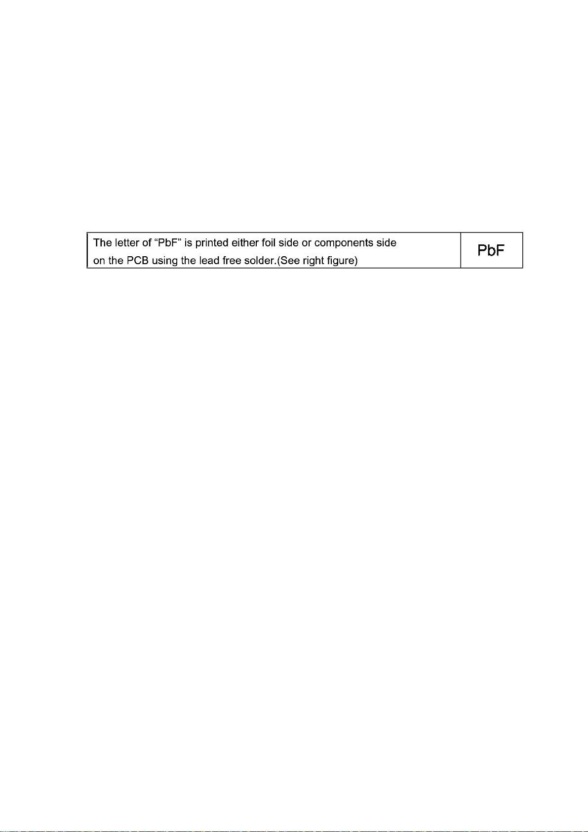
3.2. General Description About Lead Free Solder (PbF)
The lead free solder has been used in the mounting process of a ll electrical components on the printed circuit board s used for this
equipment in considering the globally environmental conservation.
The normal solder is the alloy of tin (Sn) and lead (Pb). On the other hand, the lead free solder is the alloy mainly consists of tin
(Sn), silver (Ag) and Copper (Cu), and the melting point of the lead free solder is higher approx.30°C (86°F) more than that of the
normal solder.
Distinction of PCB Lead Free Solder being used
Service caution for repair work using Lead Free Solder (PbF)
• The lead free solder has to be used when repairing the equipment for which the lead free solder is used.
(Definition: The letter of “PbF” is printed on the PCB using the lead free solder.)
• To put lead free solder, it should be well molten and mixed with the original lead free solder.
• Remove the remaining lead free solder on the PCB cleanly for soldering of the new IC.
• Since the melting point of the lead free solder is higher than that of the normal lead solder, it takes the longer time to melt the
lead free solder.
• Use the soldering iron (more than 70W) equipped with the temperature control after setting the temperature at 350±30°C
(662±86°F).
Recommended Lead Free Solder (Service Parts Route.)
• The following 3 types of lead free solder are available through the service parts route.
RFKZ03D01KS-----------(0.3mm 100g Reel)
RFKZ06D01KS-----------(0.6mm 100g Reel)
RFKZ10D01KS-----------(1.0mm 100g Reel)
Note
* Ingredient: tin (Sn) 96.5%, silver (Ag) 3.0%, Copper (Cu) 0.5%, Cobalt (Co) / Germanium (Ge) 0.1 to 0.3%
3.3. Important Notice 1:(Other than U.S.A. and Canadian Market)
1. The service manual does not contain the following information, because of the impossibility of servicing at componen t level
without concerned equipment/facilites.
a. Schematic diagram, Block Diagram and PCB layout of MAIN PCB.
b. Parts list for individual parts for MAIN PCB.
When a part replacement is required for repairing MAIN PCB, replace as an assembled parts. (MAIN PCB)
2. The following category is/are recycle module part. please send it/them to Central Repair Center.
• TRV/MAIN PCB MODULE (RFKNB15EB: DMP-B15EB)
• TRV/MAIN PCB MODULE (RFKNB15EE: DMP-B15EE)
• TRV/MAIN PCB MODULE (RFKNB15EG: DMP-B15EG)
7
Page 8
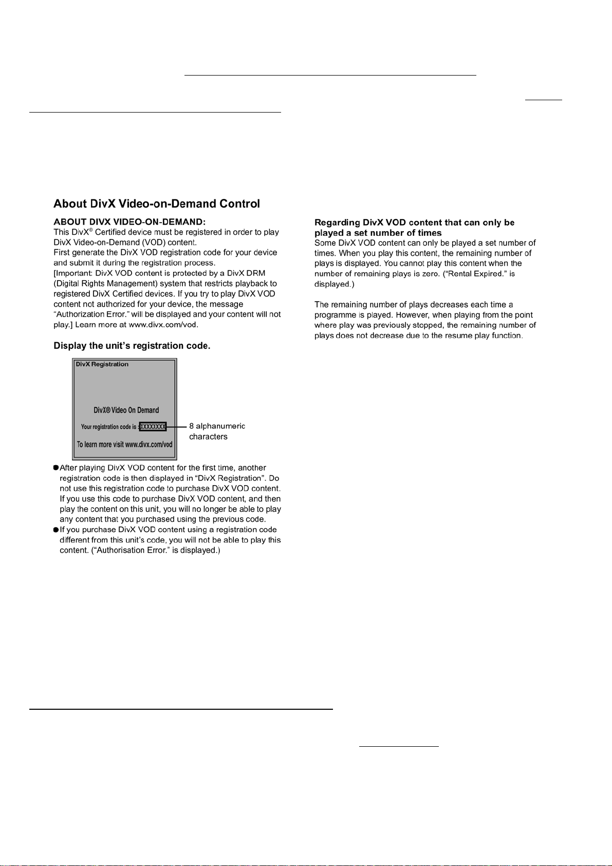
3.4. Caution for DivX
Please will always pass the customer “Warning for Customers Who Use the DivX Video-on-Demand content.” with the product and
get it when you unavoidably exchange EEPROM or P.C.B. including EEPROM (When the product is exchanged, it is the same.).
You must use print attached to service part (EEPROM or P.C.B. including EEPROM) or must use copy of print below as “Warning
for Customers Who Use the DivX Video-on-Demand content.”
Information needed without fail for the customer for whom it is used continuing DivX Video-on-Demand Service to “Manual for the
customer” is recorded.
Appendix:
*Parts that memorize user’s information are only EEPROM.
*The registration of Registration Code is possible for half a year up to 6 recorders up to 10 recorders a year.
Registration Code is memorized in EEPROM (Main P.C.B.).
If exchange above P.C.B. or EEPROM, new registration Code differ from previous Registration Code will be generated.
In this case if your customer uses DivX Video-on-Demand service, he/she will no longer be able to play any content that he/she purchased under that same registration code.
Therefore your customer will need to obtain and register the new registration code.
*Copy this page and cut on the dotted line and give the lower half to your customer.
3.5. Manual for Customer
Warning for Customers Who Use the DivX Video-on-Demand content.
1. The registration code has been changed for the repair of the product or the product exchange.
2. Obtain and register a new registration code, otherwise you will no longer be able to play DivX Video-on-Demand content.
3. Follow the procedure on the DivX Video-on-Demand web site to register at http://vod.divx.com/
*If you do not use the DivX Video-on-Demand content, please ignore this warning.
8
.
Page 9
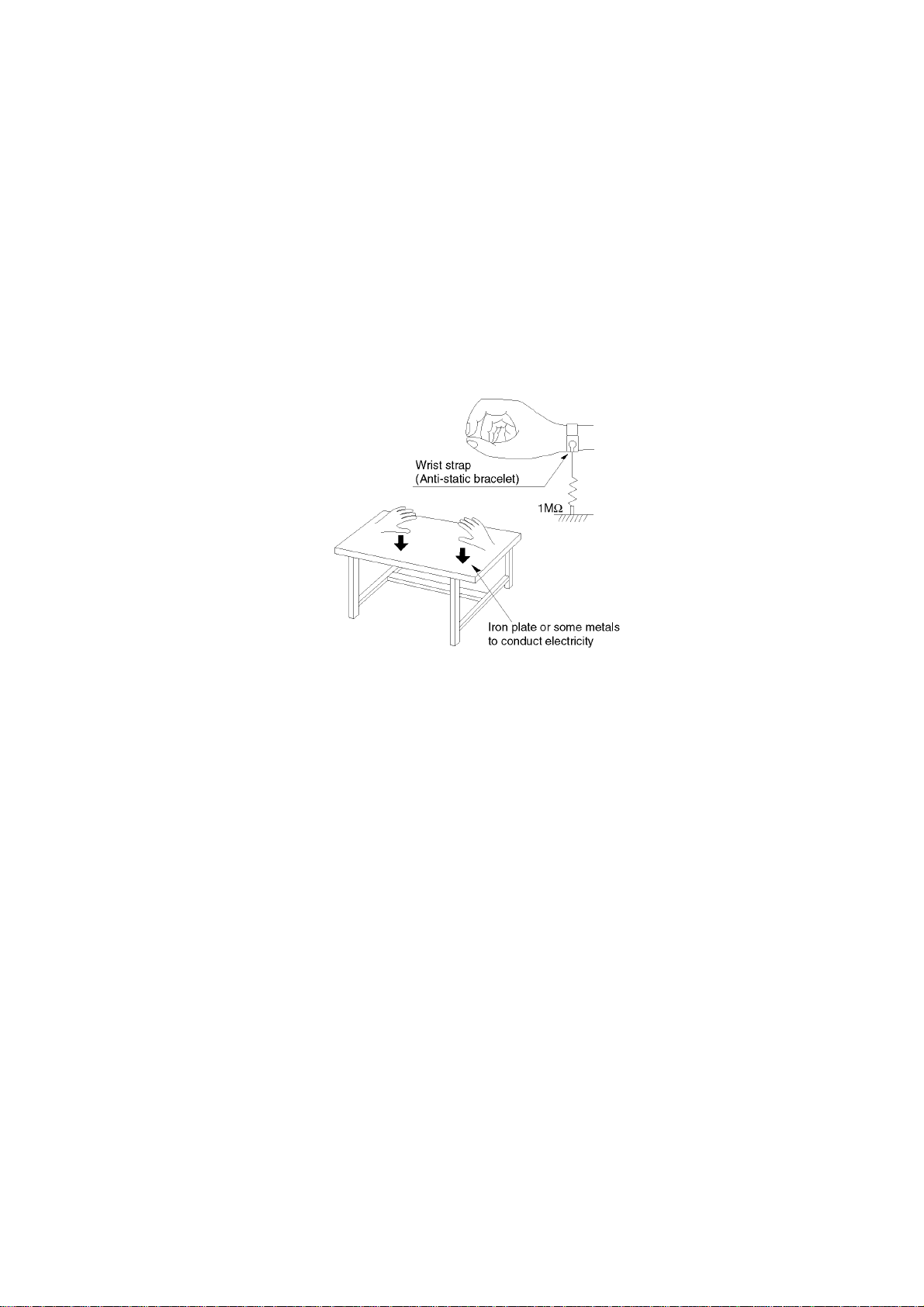
3.6. Static Electricity Protection Measures
• The laser diode in the traverse unit (optical pick-up) may break down due to potential difference caused by static electricity of
clothes or human body.
So, be careful of electrostatic breakdown during repair of the traverse unit (optical pick-up).
3.7. Ground for electrostatic breakdown prevention
• As for parts that use optical pick-up (laser diode), the optical pick-up is destroyed by the static electricity of the working environment.
Repair in the working environment that is grounded.
3.7.1. Work table grounding
• Put a conductive material (sheet) or steel sheet on the area where th e traverse unit (optical pick-up) is placed, and gro und the
sheet.
3.7.2. Human body grounding
• Use the anti-static wrist strap to discharge the static electricity from your body.
3.8. Handling of Traverse unit (optical pick-up)
1. Do not subject the traverse unit (optical pick-up) to hard shock as it is high precision mechanism.
2. Install the traverse unit, and then remove the short pin to discharge.
Connect the connector in a short time.
3. Take care not to apply excessive stress to the flexible cable.
4. Do not turn the variable resistor (laser power adjustment).
It has already been adjusted.
9
Page 10
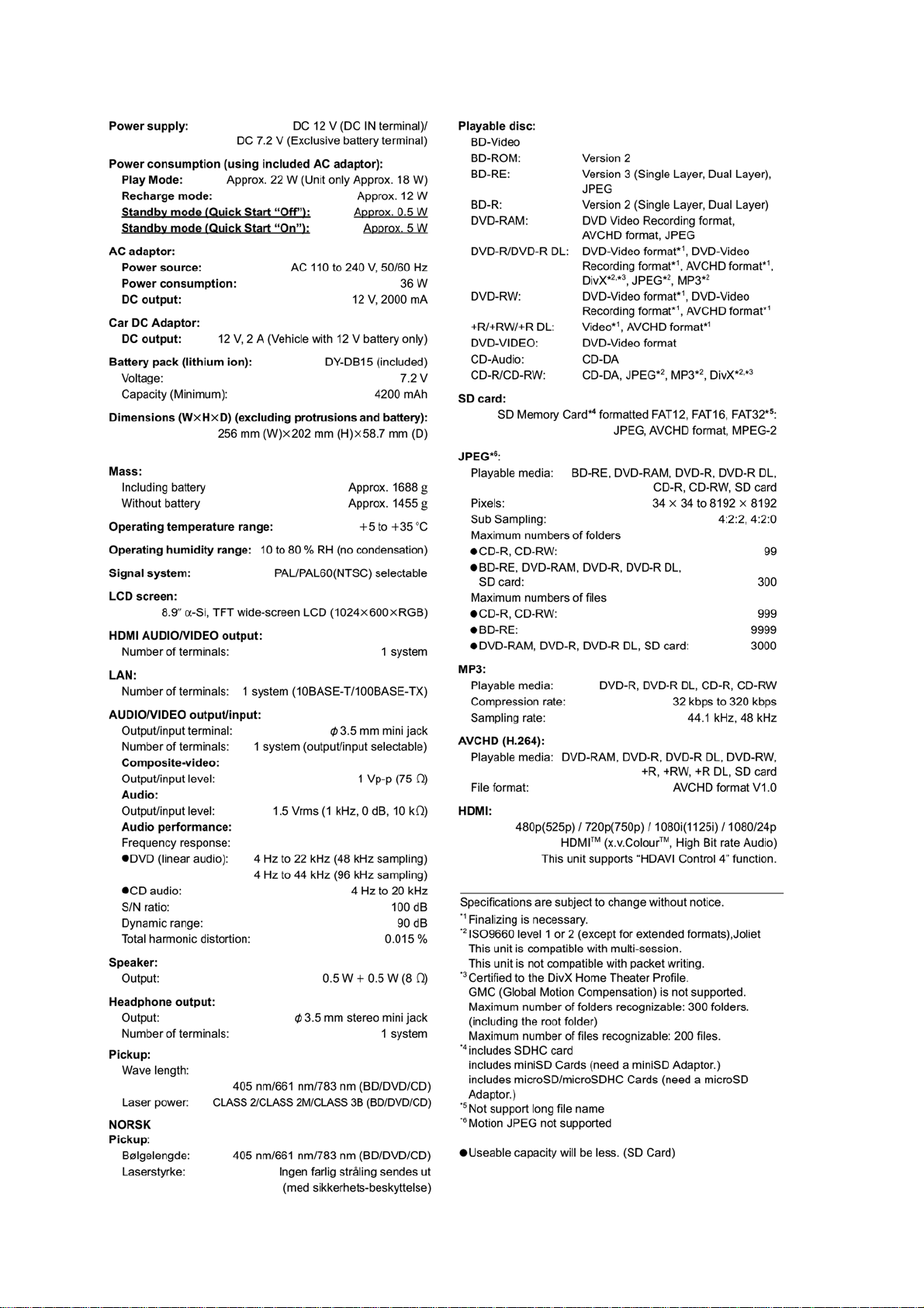
4 Specifications
10
Page 11
4.1. Accessories
• AC adaptor
(RFEA219W-AA).................................................1 pc.
• Remote control
(N2QAJC000016)................................................1 pc.
• AC power supply cord (DMP-B15EB)
(K2CT3CA00004)................................................1 pc.
• AC power supply cord (DMP-B15EE/EG)
(K2CQ2CA00006)...............................................1 pc.
• Audio/Video cable
(K2KC4CB00026)................................................1 pc.
• Car DC Adaptor
(RFEC206P-Y)....................................................1 pc.
• Headrest Mounting Bracket
(RXQ1706)..........................................................1 pc.
• Safety belt
(RFC0150-K).......................................................1 pc.
• Cleaning cloth
(RFE0215)...........................................................1 pc.
• Button-type battery for remote control.................1 pc.
• Rechargeable battery pack................... ........... ....1 pc.
4.2. Others (Licenses)
11
Page 12
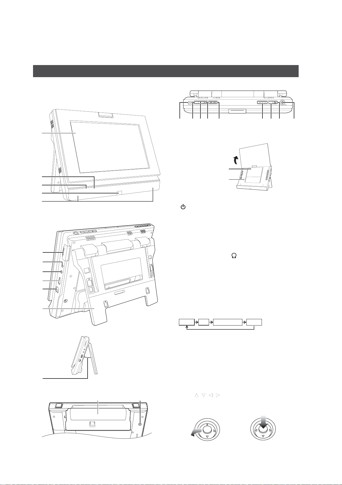
5 Location of Controls and Components
Overview
The Unit
Instructions for operations are generally described using the
remote control in these operating instructions.
Front View
1
2
3
4
5
Rear View
6
7
8
9
10
11
Top View
RETURN
AVSELECT
VOLUME
OPTION
14 15 16 17 19 20 21 2218
1 LCD screen
When the screen is opened
Disc lid
[OPEN]
2 [CHARGE] indicator
While recharging the battery pack, this indicator lights up.
3 [ ] indicator
When the unit is connected to the AC mains supply, this
indicator lights up in standby mode and goes out when the
unit is turned on.
4 Remote control signal sensor
5 Speaker
6 SD card slot
7 Audio/video input/output terminal
8H
eadphone terminal [ ]
(3.5 mm stereo mini jack)
9 HDMI AV OUT terminal
10 LAN terminal
11 Stand
12 Stopper wire
13 DC IN terminal
14 Turn the unit on and off
15 Switch the media to playback
It will switch ever y time it is pressed.
PUSH:OK
Side View
12
Bottom View
Battery pack (included)
13
DISC SD
16 Stop
17 Playback
18 Skip title numbers, etc.
19 Adjust the volume
20
Show the OPTION menu
21 Return to previous screen
22 Selection/OK
To select:
Tilt up, down, left, or
right (
[
, , , ])
Example:
To select left item
12
AUXNETWORK
To enter :
Press straight in
Example:
To enter the operation
Page 13
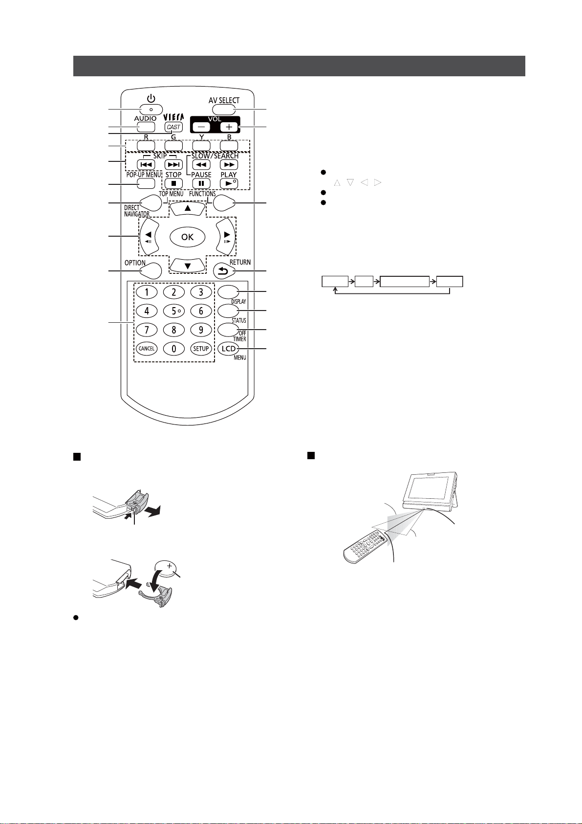
Insert the button-type battery (included)
Pull out the holder.
Insert the battery and return the holder.
Keep the button-type battery out of reach of children to
prevent swallowing.
Range of use
1 Turn the unit on and off
2 Select audio
3 Show the Home screen of the VIERA CAST
4 Use according to the instructions on the screen
5 Basic operations for playback
6 Show Pop-up menu
7 Show Top menu/Direct Navigator
8 Selection/OK, Frame-by-frame
To select: Press up, down, left, or right
(
[
, , , ])
To enter: Press [OK]
Frame forward / Frame backward:
(While paused) press left or right ([][])
9 Show the OPTION menu
10 Select title numbers, etc./Enter numbers
or characters
11 Switch the media to playback
It will switch every time it is pressed.
12 Adjust the volume
13 Show FUNCTIONS menu
14 Return to previous screen
15 Show on-screen menu
16 Show status messages
17 Turn the unit off automatically
18 Change the screen settings
Remote control
1
4
8
9
7
5
6
10
14
12
18
17
11
13
15
16
2
3
Bottom
Pull out while pressing here
A
facing up
Lithium battery: CR2025
DISC SD
Within 20 degrees angle
either up or down
Remote control transmitter
Within approx. 7 m in front
AUXNETWORK
Remote control
signal sensor
Within 30 degrees angle
either left or right
13
Page 14
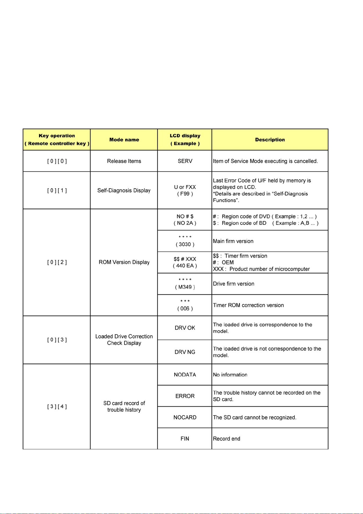
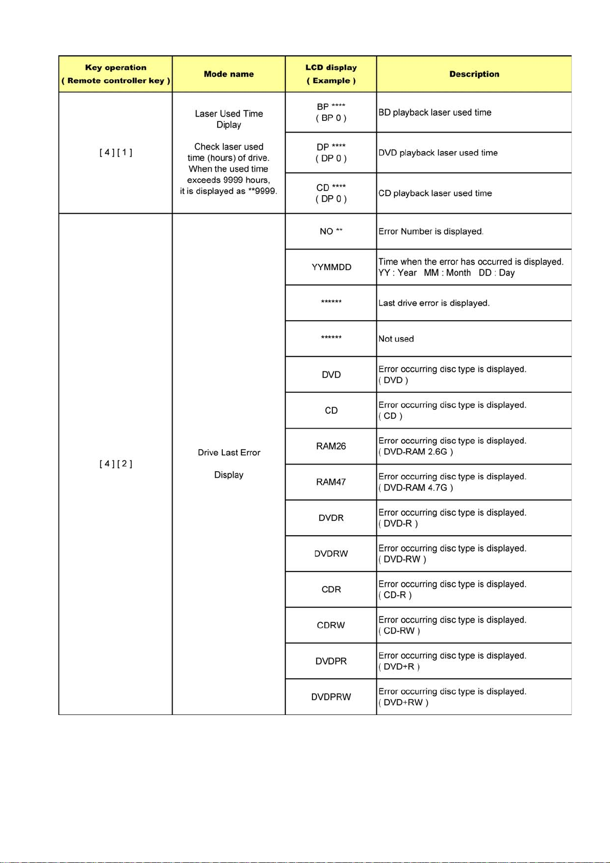
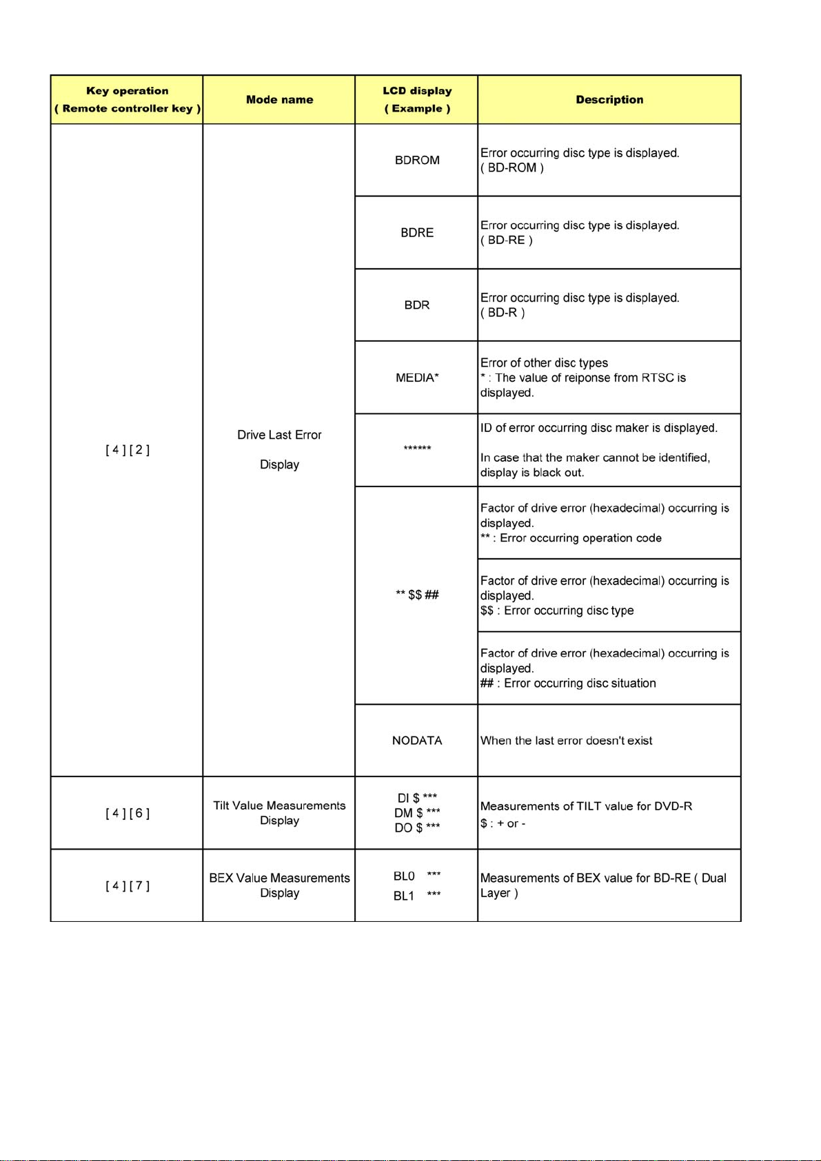
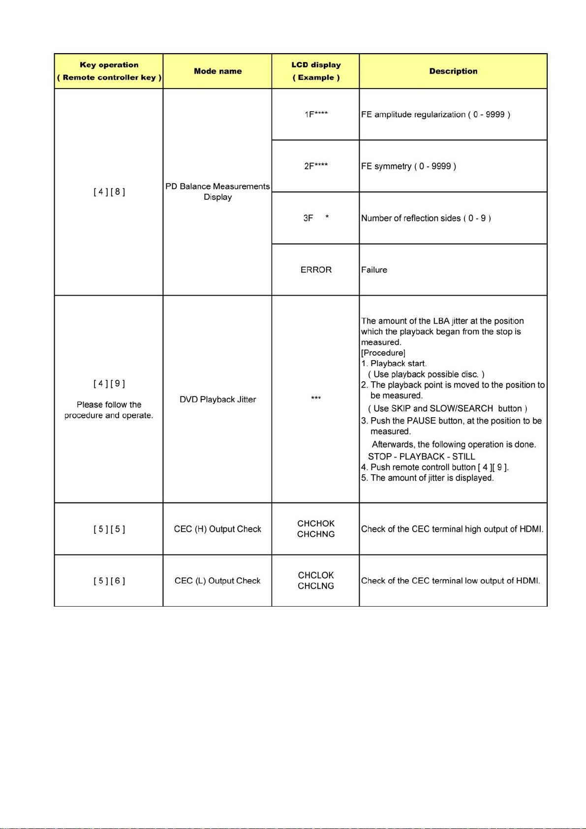
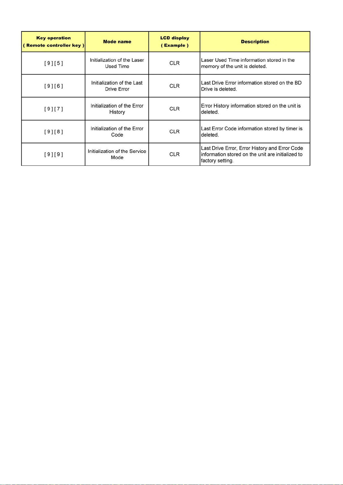
6 Service Mode
Information necessary for service can be displayed.
Service mode setting :
1. Turn the power off.
2. Press the [ PLAYBACK ] [ VOLUME - ] and [ OPTION ] button simultaneously for five seconds.
3. It is displayed on LCD as [ SERV ]. :It is shown to have entered the service mode.
([PLEASE WAIT] is displayed previously according to the A/V mode.)
4. The command is transmitted by attached remote control.
Method of making clear service mode : Press the power button (power off).
The display of information to each command is as follows.
Note : Do not use it excluding the designated command.
14
Page 15
1516171819
Page 16
Page 17
Page 18
Page 19
7 Troubleshooting Guide
7.1. Self-Diagnosis Functions
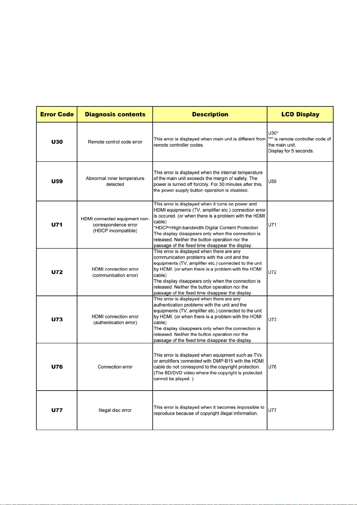
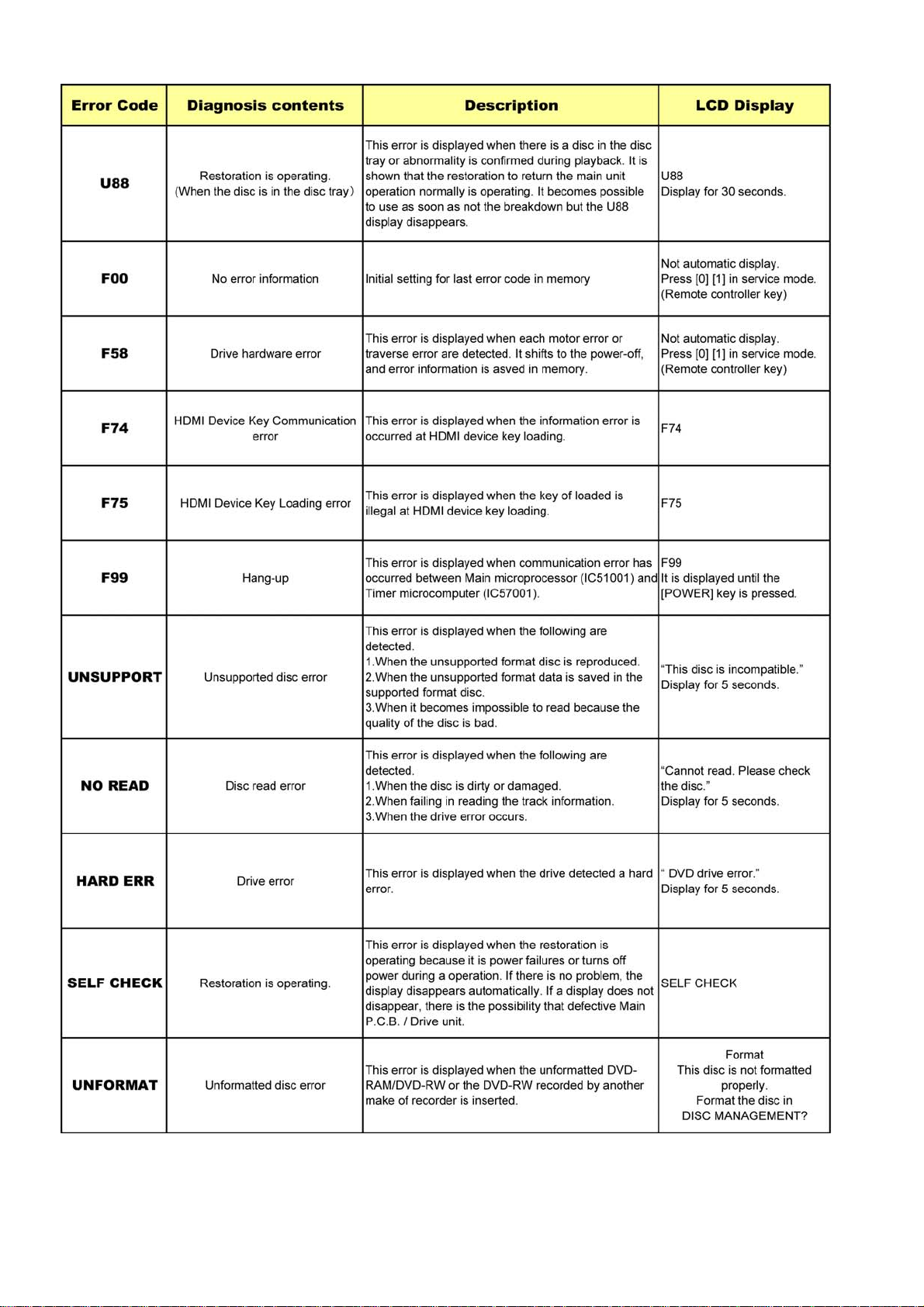
Self-Diagnosis Function provides information for errors to service personnel by Self-Diagnosis Display when any error has
occurred.
U** and F** are stored in memory and held.
You can check last error code by transmitting [0] [1] of Remote Controller in Service Mode.
In case of clear the self-diagnosis display, remove the battery pack and the AC adaptor from the main unit after the power of the
mein unit is turned off.
Page 20
20
Page 21

8 Service Fixture & Tools
Part No. Uses Pcs Interchangeability with Old Fixture Tools
----- New CD-R disc 1
----- SD DIAG CARD <128MB - 2GB>
(SDHC memory card cannot be used)
RFKZ0139 Serial Cable
(PC-Main P.C.B. (P51601)/6pin)
RFKZ0515 BD-ROM test disc 1
RFKZ0514 DVD-RAM test disc 1
RFKZ0516 CD-ROM test disc 1
RFKZ03D01KS Lead Free Solder (0.3mm/100g Reel) Sharing with EH55/EH75V/XP10/XW30 Series
RFKZ06D01KS Lead Free Solder (0.6mm/100g Reel) Sharing with EH55/EH75V/XP10/XW30 Series
RFKZ10D01KS Lead Free Solder (1.0mm/100g Reel) Sharing with EH55/EH75V/XP10/XW30 Series
RFKZ0316 Lead Free Solder with Low Melting Point
for Unsolder (50g)
RFKZ0328 Flux Sharing with EH55/EH75V/XP10/XW30 Series
1
1 Sharing with DVD Decoder
Sharing with EH55/EH75V/XP10/XW30 Series
21
Page 22
9 Disassembly and Assembly Instructions
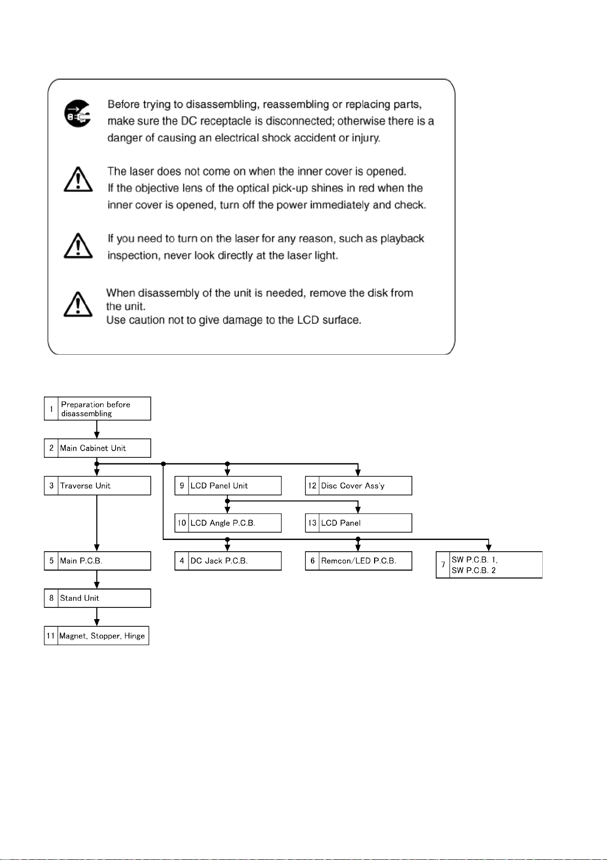
9.1. Disassembly Flow Chart
22
Page 23
9.2. PCB Location
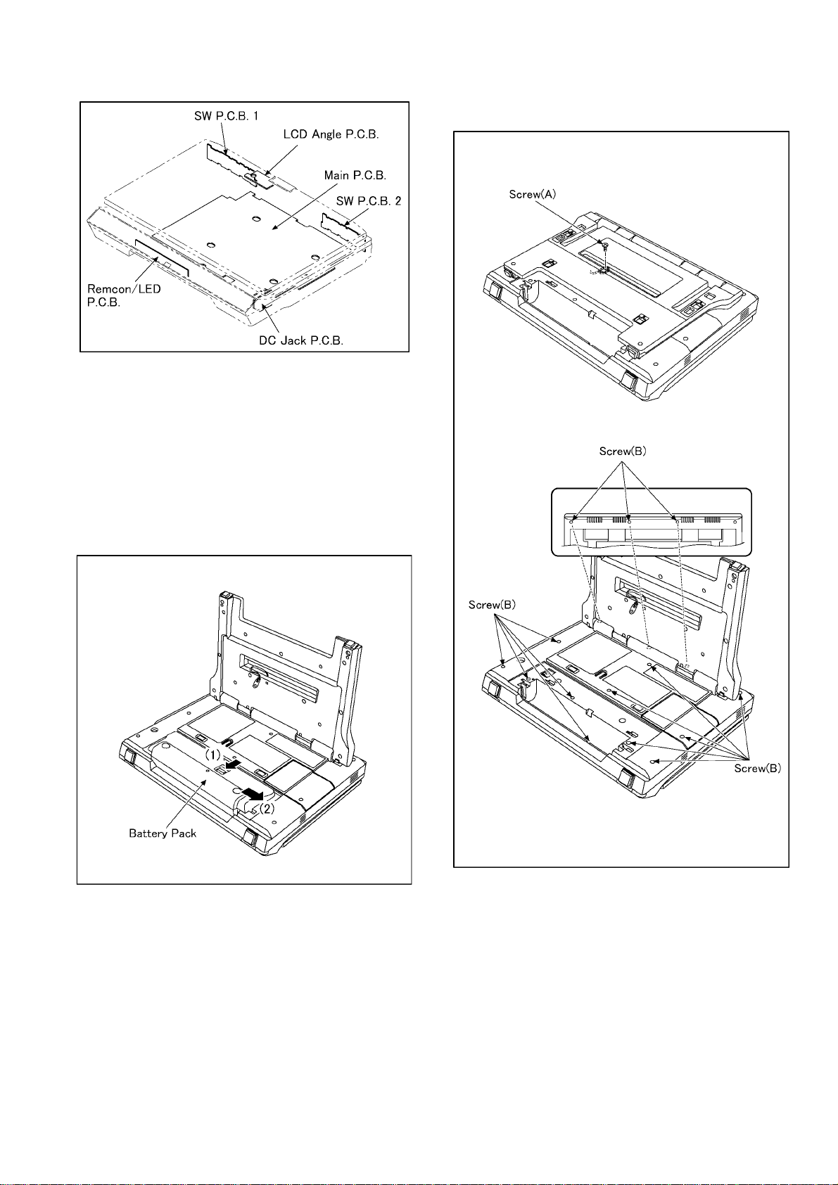
9.2.1. Preparation before disassembling
NOTE:
When servicing and reassembling, remove the SD memory
card and the disc from the unit.
1. Turn off power.
2. Remove the SD memory card and the disc.
3. While keep pressing the battery pack in the direction of
the arrow(1), slide the battery pack in the direction of the
arrow(2) and remove it.
9.2.2. Main Cabinet Unit
1. Unscrew the 1 screw (A).
2. Unscrew the 14 screws (B).
23
Page 24
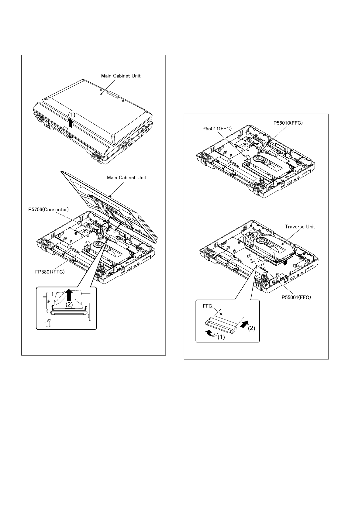
3. Lift the main cabinet unit in the direction of the arrow(1).
4. Pull out the P5706(connector) and the FP8801(FFC), and
then remove the main cabinet unit.
9.2.3. Traverse Unit
NOTE:
The countermeasure against static electricity is necessary
when servicing the surrounding of traverse unit.
Moreover, the tr a verse unit is the precision optical part.
Take care not to touch surrounding of the lens and not to
shock to the traverse unit.
1. Pull out the P55010(FFC) and the P55011(FFC).
2. Lift the traverse unit in the direction of the arrow(1), pull
out the P55001(FFC), and then remove the traverse unit.
NOTE:
When remove the FFC, pull out the FFC straight in the
direction of the arrow(2).
NOTE:
When remove the FFC, pull up the locking tab in the direction of the arrow (1), and then remove the FFC i n the direction of the arrow (2).
24
Page 25
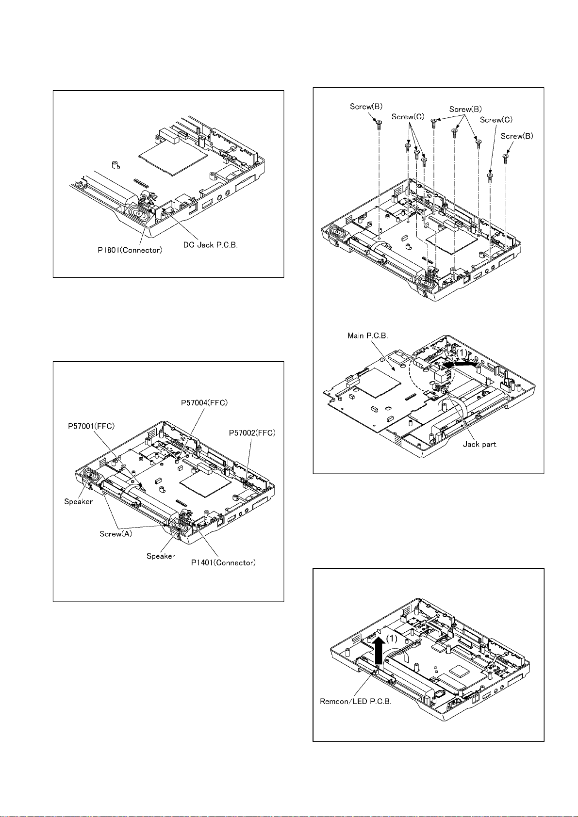
9.2.4. DC Jack P.C.B.
1. Pull out the P1801(connector), and then remove the DC
Jack P.C.B..
9.2.5. Main P.C.B.
1. Unscrew the 2 screws (A), and then remove the
speaker(L/R).
2. Pull out the P57001(FFC), the P57002(FFC), the
P57004(FFC) and the P1401(connector).
3. Unscrew the 5 screws (B).
4. Unscrew the 4 screws (C), and then remove the main
P.C.B..
NOTE:
Pass through the jack part in the direction of the arrow(1)
when installing the main P.C.B..
9.2.6. Remcon/LED P.C.B.
1. Lift the remcon/LED P.C.B. in the direction of the
arrow(1), and then remove it.
25
Page 26
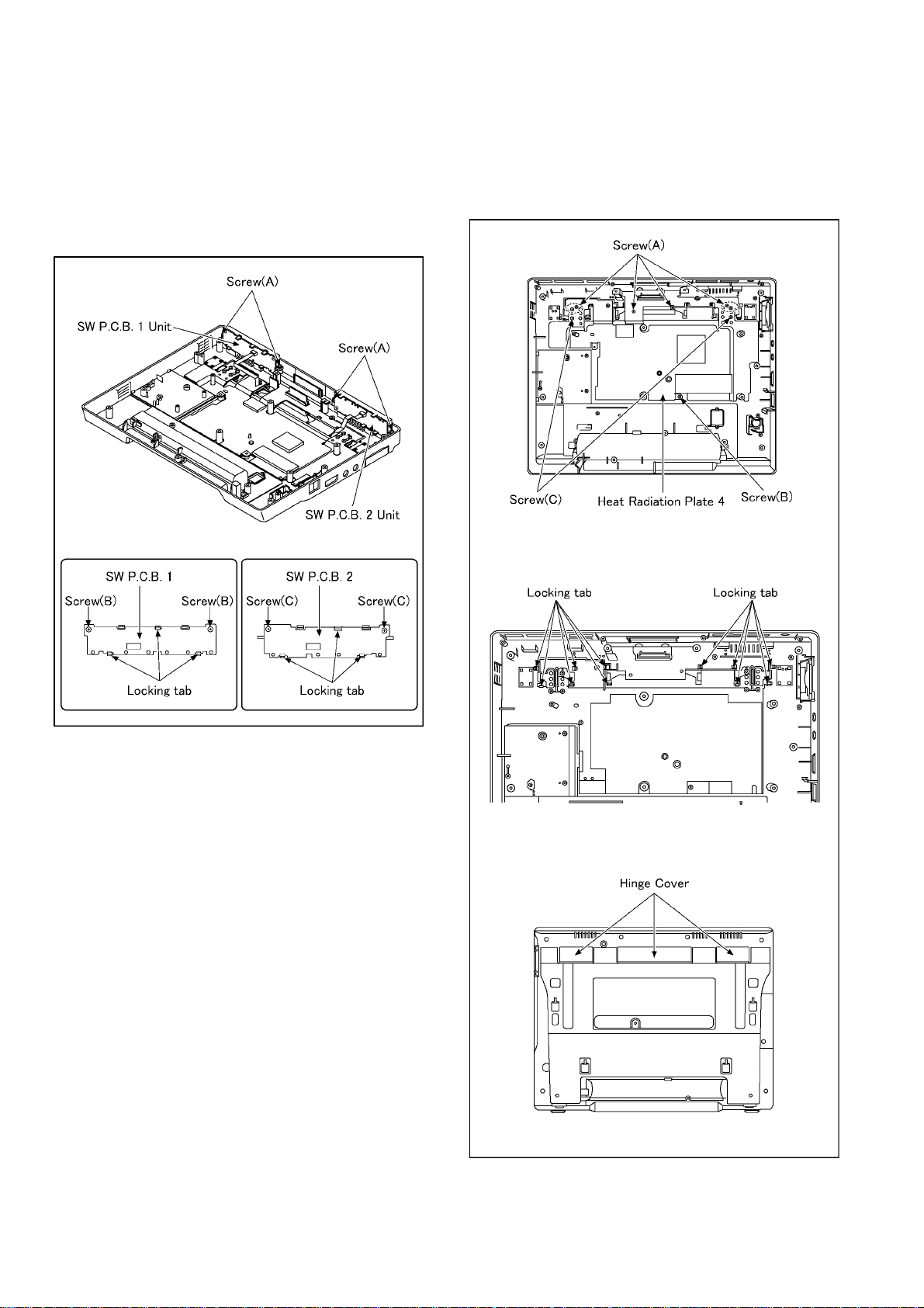
9.2.7. SW P.C.B. 1, SW P.C.B. 2
1. Unscrew the 4 screws (A), and then remove the SW
P.C.B. 1 unit and SW P . C.B. 2 unit.
2. Unscrew the 2 screws (B).
3. Remove the 3 locking tabs, and then remove the SW
P.C.B. 1.
4. Unscrew the 2 screws (C).
5. Remove the 3 locking tabs, and then remove the SW
P.C.B. 2.
9.2.8. Stand Unit
1. Unscrew the 6 screws (A).
2. Unscrew the 1 screw (B).
3. Unscrew the 2 screws (C), and then remove the heat
radiation plate 4.
4. Remove the 11 locking tabs, and then remove the hinge
cover.
26
Page 27
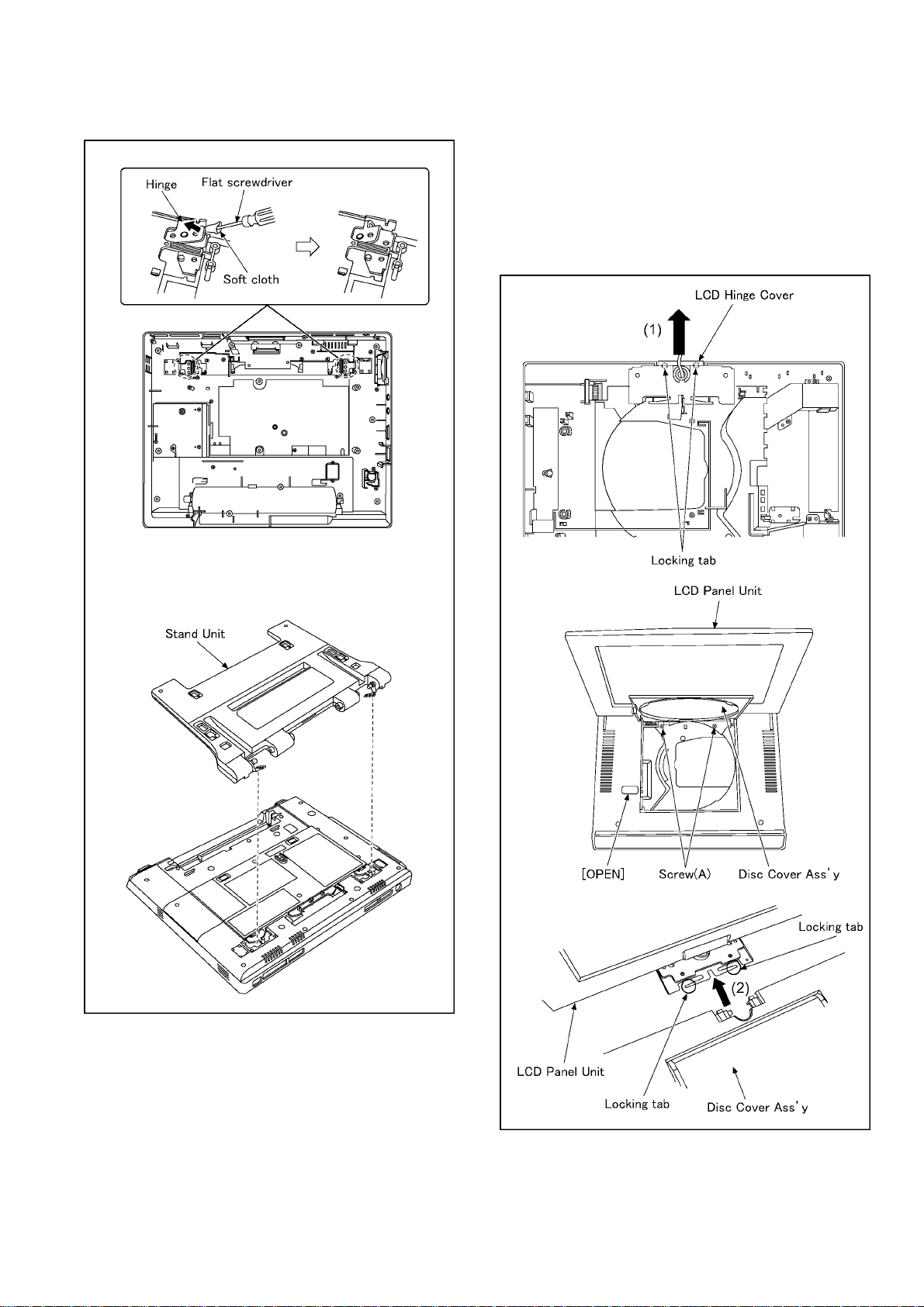
5. Remove the hinge for the stand with the flat screwdriver.(Both right and left)
6. Remove the stand unit.
9.2.9. LCD Panel Unit
1. Remove the 2 locking tabs, slide the LCD hinge cover in
the direction of the arrow(1), and then remove the LCD
hinge cover.
2. Open the LCD panel unit, push the [OPEN], and then
open the disc cover ass'y.
3. Unscrew the 2 screws (A).
4. Remove the 2 locking tabs, slide the LCD panel unit in the
direction of the arrow(2), and then remove the LCD panel
unit.
NOTE:
Wrap the soft cloth around the point of the flat screwdriver
so as not to damage the bottom cabinet etc.
27
Page 28
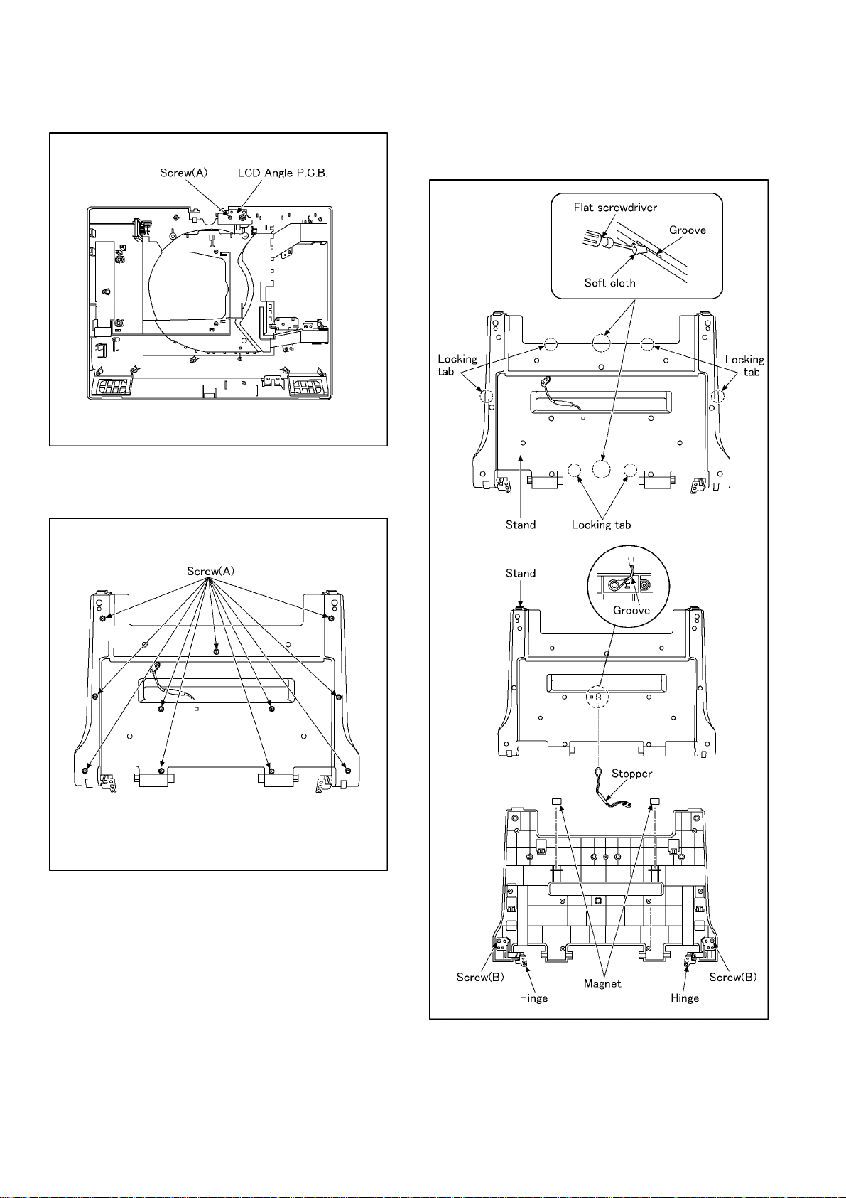
9.2.10. LCD Angle P.C.B.
1. Unscrew the 1 screw (A), and then remove the LCD angle
P.C.B..
9.2.11. Magnet, Stopper, Hinge
1. Unscrew the 11 screws (A).
2. Insert the flat screwdriver in the groove, and then remove
the 6 locking tabs.
3. Remove the stand.
4. Remove the stopper and the 2 magnets.
5. Unscrew the 2 screws (B), and then remove the
hinge(L,R).
NOTE:
When remove the stand, magnet and stopper are removed
at the same time.
Be careful to loss.
28
Page 29
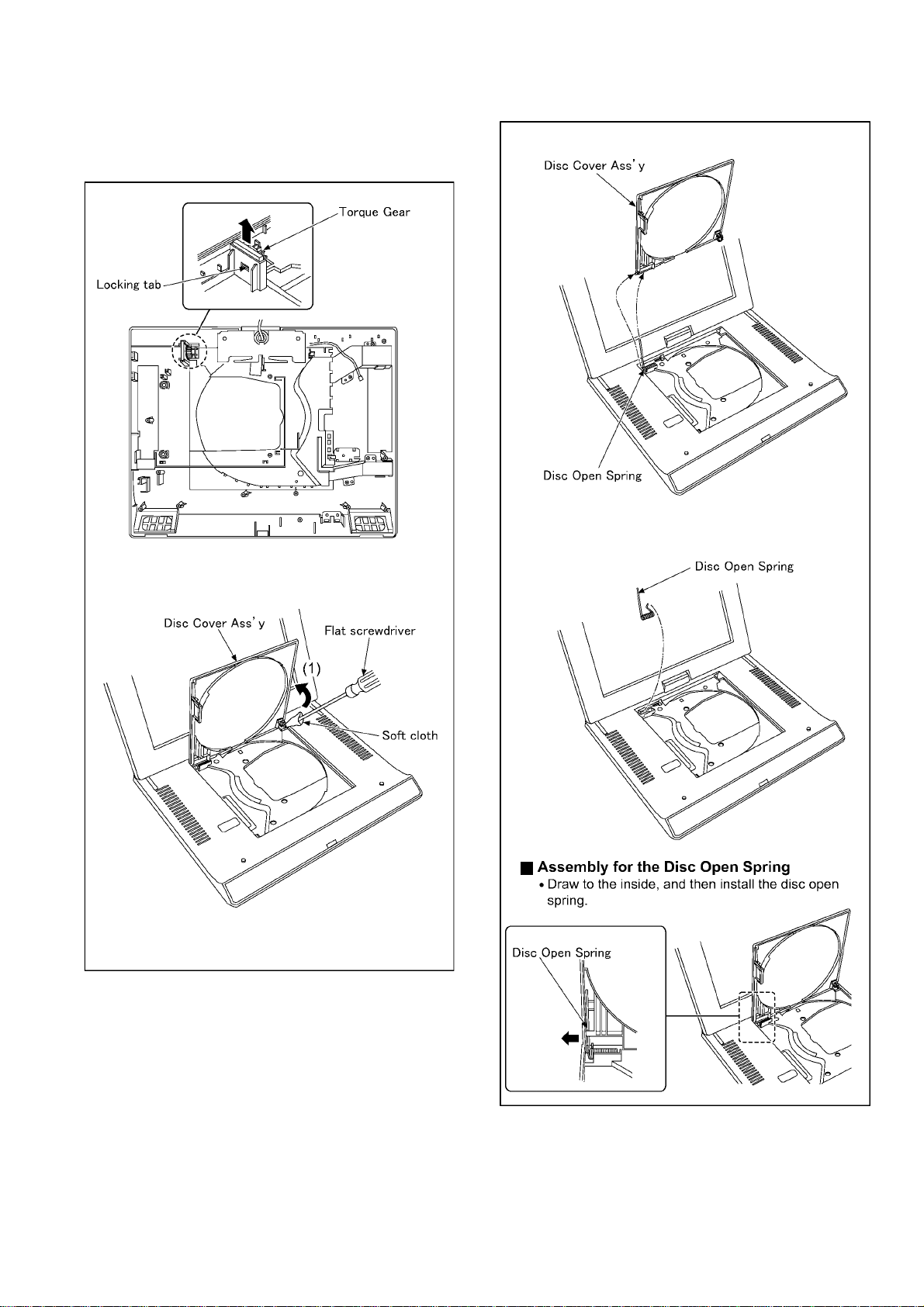
9.2.12. Disc Cover Ass'y
1. Remove the 1 locking tab, and then pull out the torq ue
gear.
2. Insert the flat screwdriver, and then remove the right edge
side of disc cover ass'y in the direction of the arrow(1).
3. Remove the disc cover ass'y noting the disc open spring.
4. Remove the disc open spring.
NOTE:
Wrap the soft cloth around the point of the flat screwdriver so as not to damage the main cabinet ass'y and
disc cover ass'y.
29
Page 30
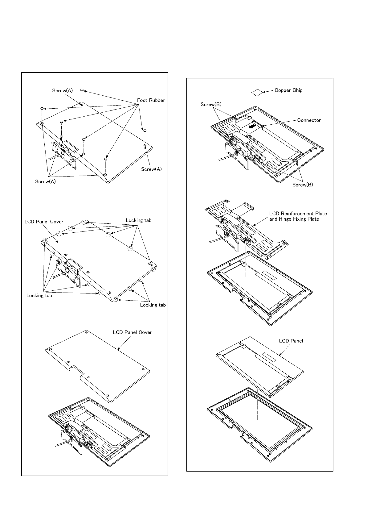
9.2.13. LCD Panel
1. Remove the 6 foot rubbers.
2. Unscrew the 6 screws (A).
3. Remove the 14 locking tabs, and then remove the LCD
panel cover.
4. Remove the copper chip.
5. Pull out the 1 connector.
6. Unscrew the 4 screws (B).
7. Remove the LCD reinforcement plate and the hinge fixing
plate.
8. Remove the LCD panel.
30
Page 31
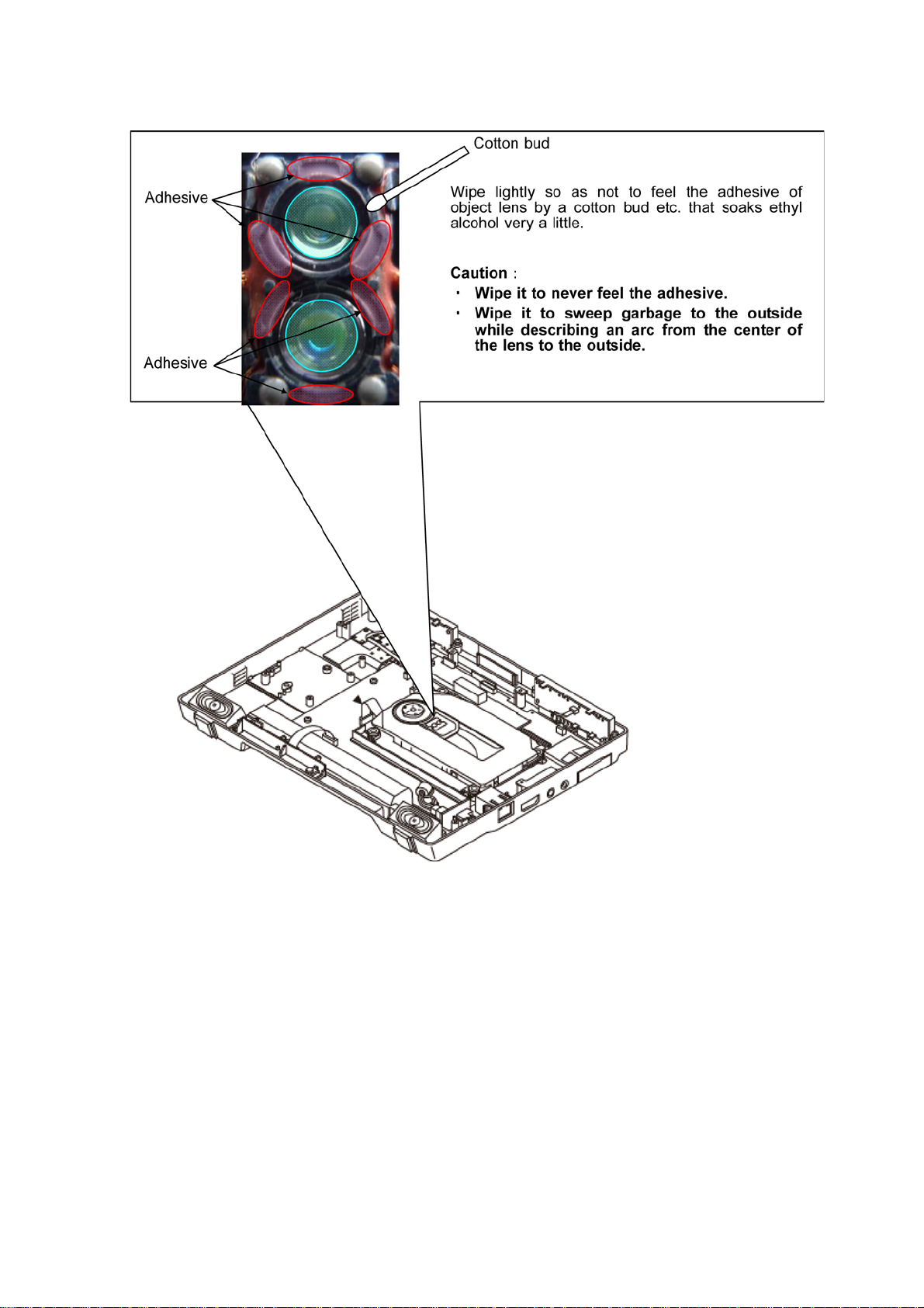
9.3. Cleaning of the Optical Pick-up
Disassemble to the item 4 (9.2.2. MAIN CABINET UNIT), and clean the optical pick-up.
31
Page 32
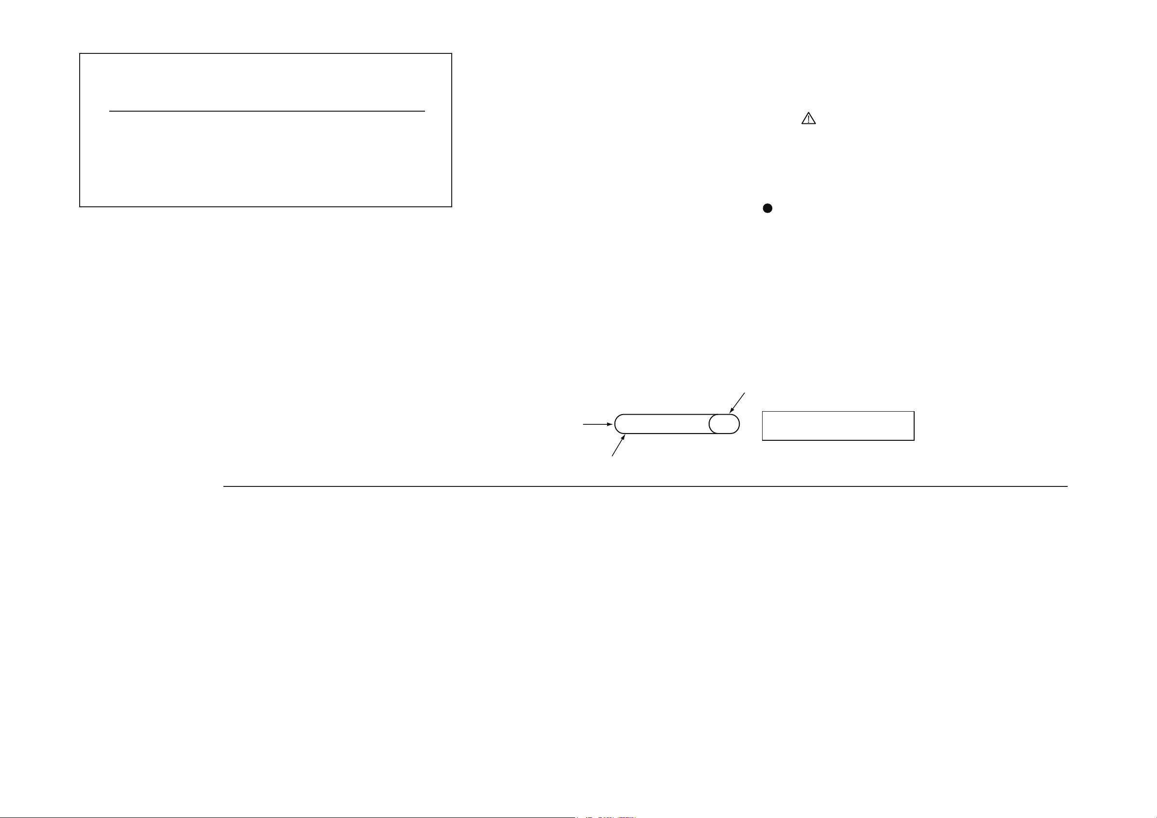
Table of contents
Service Manual
CHM0904017CE
Diagrams and Replacement
Parts List
Vol. 1
(K)...........Black Type
Colour
Model No.
DMP-B15EB
DMP-B15EE
DMP-B15EG
Portable Blu-ray Disc Player
Name of Signal
OFTR
FEP
This signal is connected
to the FEP schematic diagram.
Circuit name being connected.
6.Use the parts number indicated on the Replacement Parts List .
7.Indication on Schematic diagrams:
5.The voltage being indicated here may be include observational-error (deviation) due to
internal-resistance and/or reactance of equipment. Therefore, handle the value
indicated on here as reference.
4.Although the voltage and waveform available on here is measured with standard frame,
it may be differ from actual measurement due to modification of circuit and so on.
3.The voltage being indicated on the schematic diagram is measured in
"Standard-Playback" mode when there is no specify mode is mentioned.
2.It is only the "Test Round" and no terminal (Pin) is available on the P.C.B.
when the TP (Test Point) indicated as " " mark.
1.Although reference number of the parts is indicated on the P.C.B. drawing and/or
schematic diagrams, it is NOT mounted on the P.C.B. when it is displayed with "$" mark.
FOR SAFETY. WHEN REPLACING ANY OF THESE COMPONENTS USE ONLY THE SAME TYPE.
COMPONENTS IDENTIFIED WITH THE MARK HAVE THE SPECIAL CHARACTERISTICS
S1. About Indication of The Schematic Diagram
S1.1. Important Safety Notice
S1. About Indication of The Schematic Diagram ............................ S-1
S1.1. Important Safety Notice......................................................... S-1
S2. Block Diagram .......................................................................... S-2
S2.1. Overall Block Diagram ..........................................................S-2
S3. Schematic Diagram .................................................................. S-3
S3.1. Interconnection Diagram ....................................................... S-3
S3.2. DC Jack Schematic Diagram ................................................ S-4
S3.3. SW_1 Schematic Diagram .................................................... S-5
S3.4. SW_2 Schematic Diagram .................................................... S-6
S3.5. Remote Control LED Schematic Diagram............................. S-7
S3.6. LCD_Angle Schematic Diagram ...........................................S-7
S4. Print Circuit Board .................................................................... S-8
S4.1. DC Jack P.C.B. ...................................................................... S-8
S4.2. SW P.C.B. 1 ..........................................................................S-8
S4.3. SW P.C.B. 2 ..........................................................................S-9
S4.4. Remote Control LED P.C.B. ................................................ S-10
S4.5. LCD Angle SW P.C.B. .........................................................S-10
S5. Replacement Parts List .......................................................... S-11
S6. Exploded View .......................................................................S-14
S6.1. Frame and Casing Section (1) ............................................ S-14
S6.2. Frame and Casing Section (2) ............................................ S-15
S6.3. Packing Parts and Accessories Section .............................. S-16
S-1
Page 33
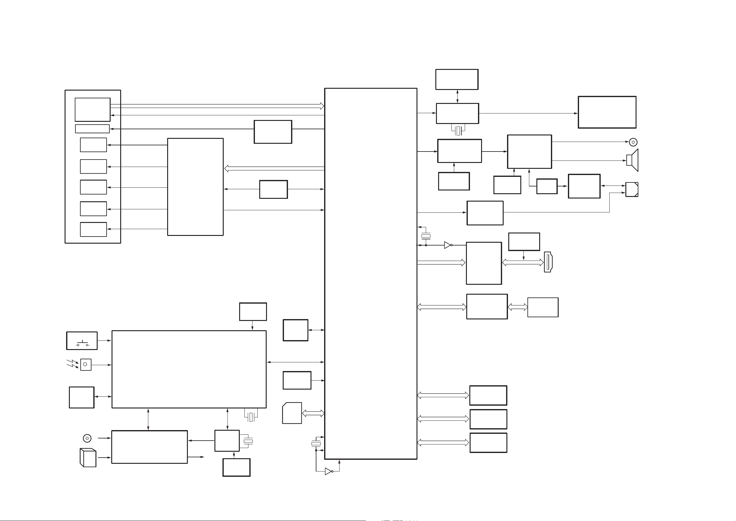
S2. Block Diagram
SPEAKER
OPERATION
DC JACK
BATTERY
HDMI
TERMINAL
REMOTE
SENSOR
HEADPHONES
DMP-B15 OVERALL BLOCK DIAGRAM
TRAVERSE MECHANISM UNIT
OPTICAL
PICK-UP
UNIT
FOCUS
COIL
TRACKING
COIL
BEX
MOTOR
TRAVERSE
MOTOR
SPINDLE
MOTOR
IC55005
MOTOR DRIVE
IC51001
SERVO&VIDEO/AUDIO
PROCESSOR/SYSTEM
CONTROL
IC57001
OPERATION CONTROL
X57001
(10MHz)
X51003
(33.3MHz)
X57081
(32.768kHz)
IC57005
EEPROM
IC51601
EEPROM
IC57006
RTC
IC1001,1002,1102,1103,1201,1401,
1451-1453,1461,1601
POWER SUPPLY
(DC-DC CONVERTER/
REGULATOR/CHARGE) CIRUIT
SD
CARD
ETHER NET
PORT
IC52001,52002
SDRAM/1Gbit
IC52201,52202
SDRAM/512Mbit
IC51301
NAND FLASH
ROM/1Gbit
IC59001
PHYSIVAL LAYER
TRANSCEIVER
IC56036
HDMI TX
LSI
IC8803
LCD TV DISPLAY
CONTROLLER
COLOR
LCD PANEL
IC4001
D/A CONVERTER
IC4008
STEREO AUDIO
POWER AMP
AV IN/OUT
IC4009,4010
SIGNAL
SELECTOR
IC3201
VIDEO
AMP
LASER DIODE
IC55901
SWITCHING
REGLATOR
CONTROLLER
IC57002
VOLTAGE
DET.
IC51003
VOLTAGE
DET.
IC8804
FLASH MEMORY
512 kbit
IC4011
VOLTAGE
DET.
IC4002
REGULATOR
IC4005
OP AMP
IC56001
REGULATOR
IC55003
RESET
IC57007
VOLTAGE
DET.
IC51005
INVERTER
X51001
(27MHz)
IC51004
INVERTER
X8801
(12MHz)
S2.1. Overall Block Diagram
S-2
Page 34
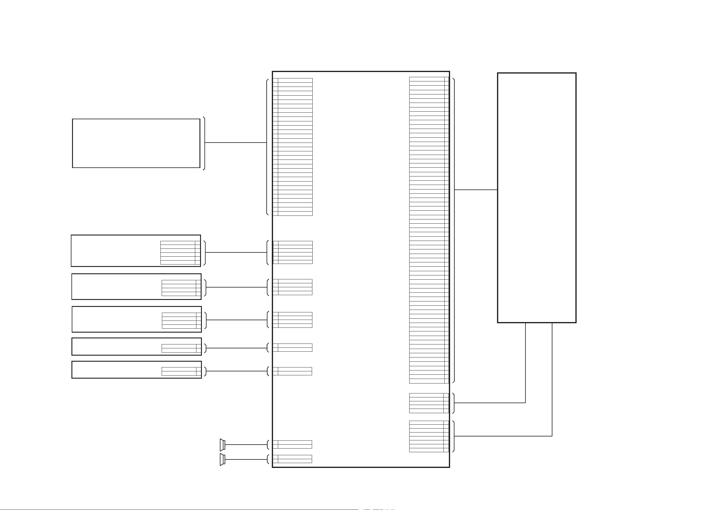
S3. Schematic Diagram
DMP-B15 INTERCONNECTION DIAGRAM
66
77
55
99
88
46
49
48
50
47
43
42
44
3939
3737
3838
40
3333
3434
3030
2929
3131
2626
2525
2727
2222
2121
2323
1818
1717
1919
1414
1313
1515
1111
1010
1212
1616
2020
2424
2828
3232
3636
3535
41
45
58
59
54
55
51
53
52
57
56
1
33
44
22
69
71
70
63
64
60
62
61
67
68
65
66
P55001
ACT FOC2+
ACT TRK-
ACT TRK+
GNDGND
LD+
GND
RFP
GND
RFN
GND
SW2
SW3
LD+
SW1
GND
LDD SD
LDD SEN
LDD ENA
LDD Vcc
LDD GND
LDD GND
LDD Vcc
LDD GND
LDD REN
SW4
STPM SB-
STPM SA-
STPM PIC
LDD SLCK
STPM PIA
STPM SA+
STPM SB+
ACT TRK+
ACT TRK-
ACT FOC2-
LDD OSEN
LDD WEN4
LDD WEN2
LDD IIN4
LDD IIN2
Temp OUT
LDD IINR
LDD IIN3
LDD IIN5
LDD WEN3
LDD WEN5
ACT FOC1+
ACT FOC1-
LDD OSENB
LDD WENB4
LDD WENB2
LDD WENB3
LDD WENB5
FM Vcc 5V
FM Vout(+)
OEIC Vref2.2V
OEIC Vcc 5V
OEIC Vcc 5V
FM Vout(-)
ACT FOC1-
ACT FOC1+
A4(BD)/D(DVD/CD)
A2(BD)/C(DVD/CD)
A3(BD)/A(DVD/CD)
A1(BD)/B(DVD/CD)
B5C2(BD)/H(DVD/CD)
B3(BD)/F(DVD/CD)
B1(BD)/G(DVD/CD)
B6C1(BD)/E(DVD/CD)
ACT FOC2-
ACT FOC2+
2
3
1
5
4
P55010
5
6
1
3
4
2
8
7
P55011
V
U
B+
A+
NC(GND)
AB-
U+
VH+
U-
VH-
W
GND
SPEAKER (L)
2
1
4
3
P57002
2
4
3
1
6
5
P57001
2
1
4
3
P57004
GND
PW_RTC+3R3V
PW_OPR+3R3V
NC
GND
POWER-SW
GND
KEY2
NC
KEY3
KEY1
CHARGE_LED
REMOCON
STANDBY_LED
1
P57006
2
D GND
LCD_ANGLE
2
1
P1401
GND
DC IN
2
1
P4001
SPL-
SPL+
2
1
P4002
SPR-
SPR+
MAIN P.C.B.
2
4
3
1
6
5
P6201
GND
PW_RTC+3R3V
PW_OPR+3R3V
REMOCOM
CHARGE_LED
STANDBY_LED
6
7
5
9
8
27
23
18
20
19
15
14
16
11
12
10
13
17
22
21
26
24
25
30
28
29
1
3
4
2
32
31
FP8801
GND
RXIN2-
AVSS
RXIN1-
RXIN0+
NC
RXIN0-
AVSS
RXIN1+
AVSS
AVSS
RXCLK+
NC
VDD(LED)
GND
NC/XR
NC/XL
NC/YD
VDD(LED)
VDD(LED)
NC/YU
AVSS
AVSS
NC
RXCLK-
RXIN2+
NC
ADJ
VCC
AVSS
NC
VCC
LCD ASS’Y
REMOCON/LED P.C.B.
SW P.C.B. 1
2
1
4
3
P6001
NC
KEY1
POWER-SW
GND
SW P.C.B. 2
3
4
1
2
P6101
GND
NC
KEY2
KEY3
LCD ANGLE P.C.B.
2
1
P6301
LCD_ANGLE
GND
DC JACK P.C.B.
1
2
P1801
GND
DC IN
SPEAKER (R)
TRAVERSE ASS’Y
S3.1. Interconnection Diagram
S-3
Page 35
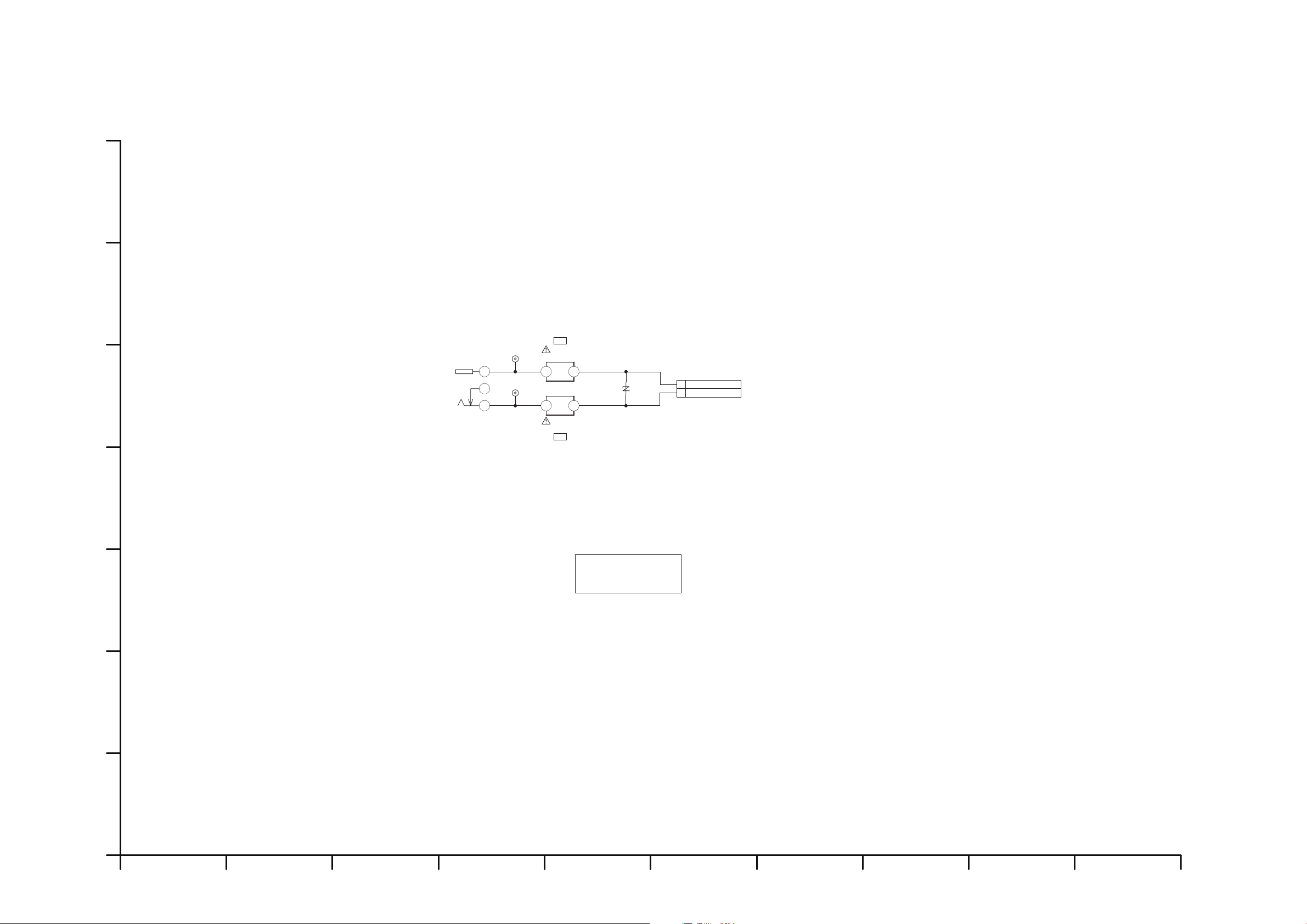
S3.2. DC Jack Schematic Diagram
Confidential
Until
CL1801
CL1802
2
1
IP1801
D1JBR015A007
2
1
IP1802
D1JBR015A007
ERZVF2M330
VA1801
132
JK1801
K2ED2B000002
1
2
K1KY02A00009
P1801
2009/2/28
4
4
GND
[ES2]
DC IN
DMP-B15EB/EE/EG
DC Jack
Schematic Diagram
10987654321
G
F
E
D
C
B
A
S-4
S-4
Page 36
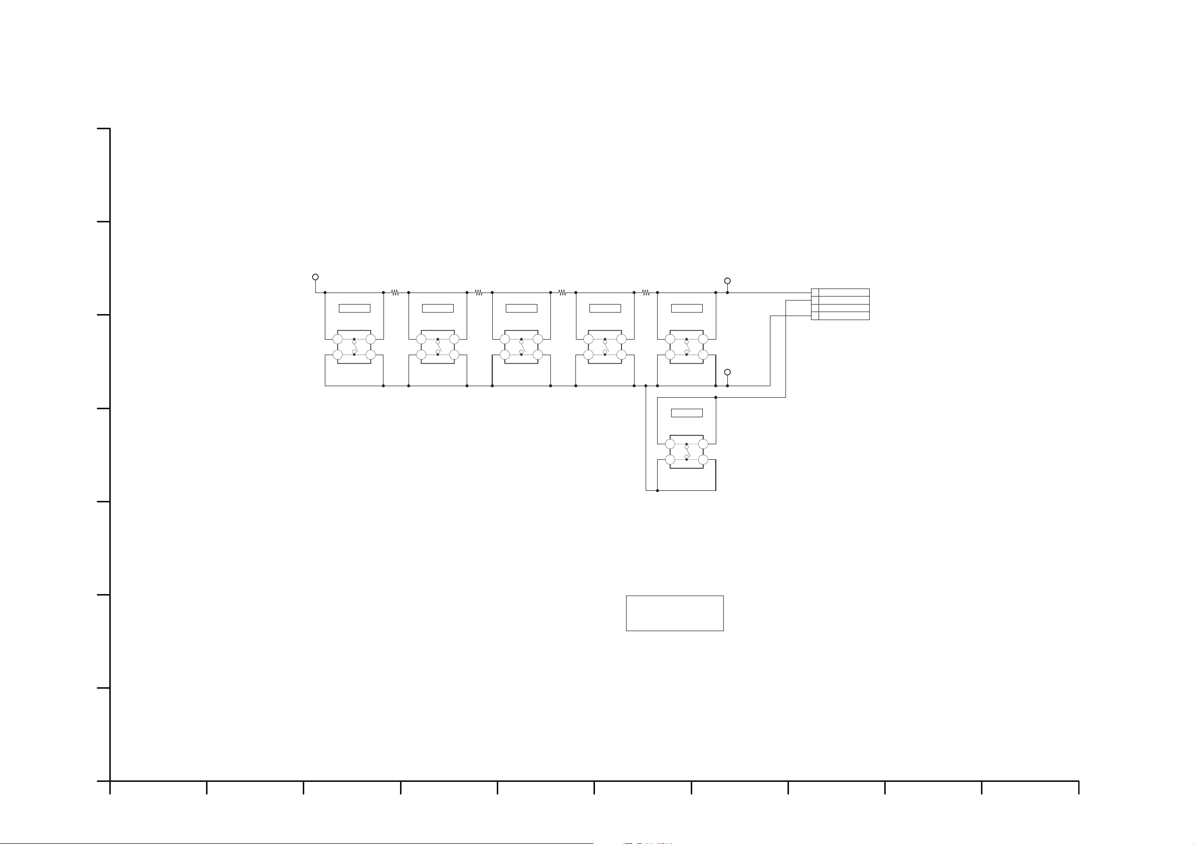
S3.3. SW_1 Schematic Diagram
Confidential
Until
TL6001
TL6003
TL6002
1
3
4
2
K1MN04AA0003
P6001
2
4
1
3
S6004
K0F111A00472
2
4
1
3
S6005
K0F111A00472
2
4
1
3
S6001
K0F111A00472
2
4
1
3
S6002
K0F111A00472
2
4
1
3
S6003
K0F111A00472
2
4
1
3
S6006
K0F111A00472
R6001
1500
R6002
2200
R6003
3300
R6004
4700
2009/2/28
GND
POWER-SW
KEY1
NC
AV SELECTSTOPPLAYCH DOWNCH UP
POWER
[ES2]
DMP-B15EB/EE/EG
SW_1
Schematic Diagram
10987654321
G
F
E
D
C
B
A
S-5
Page 37
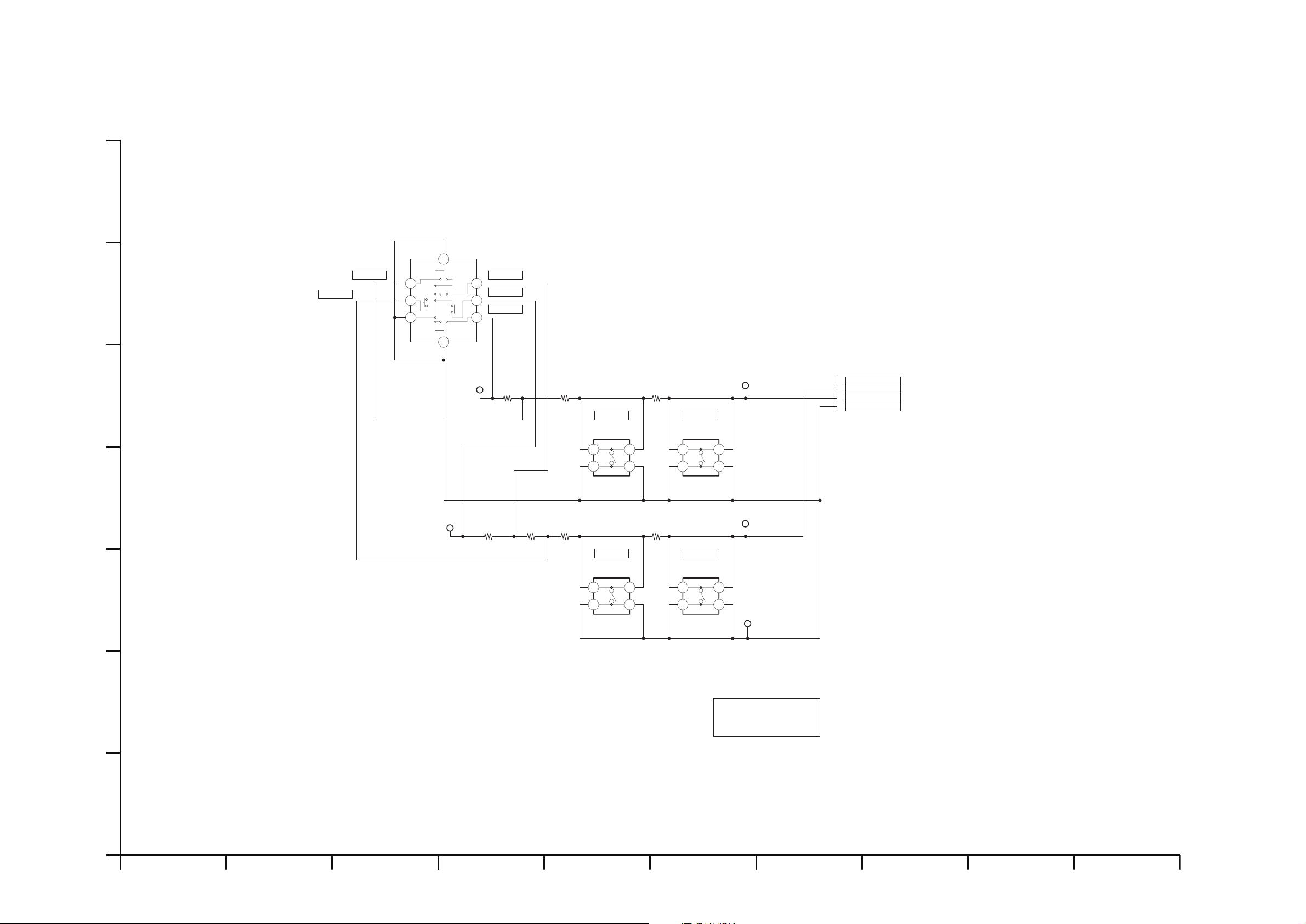
S3.4. SW_2 Schematic Diagram
Confidential
Until
2
4
1
3
S6104
K0F111A00472
2
4
1
3
S6102
K0F111A00472
2
4
1
3
S6103
K0F111A00472
2
4
1
3
S6101
K0F111A00472
TL6101
TL6102
TL6103
TL6104
TL6105
R6101
1500
R6102
2200
R6103
3300
R6104
1500
R6105
2200
R6106
3300
R6107
4700
1
3
4
2
K1MN04AA0003
P6101
3
5
2
6
4
1
7
8
C
C
C
K0C115A00002
S6105
2009/2/28
[ES2]
RETURN
VOL UP VOL DOWN
MENU
UP (A)
DOWN (C)
LEFT (D)
RIGHT (B)
ENTER (P)
GND
KEY2
KEY3
NC
DMP-B15EB/EE/EG
SW_2
Schematic Diagram
10987654321
G
F
E
D
C
B
A
S-6
Page 38
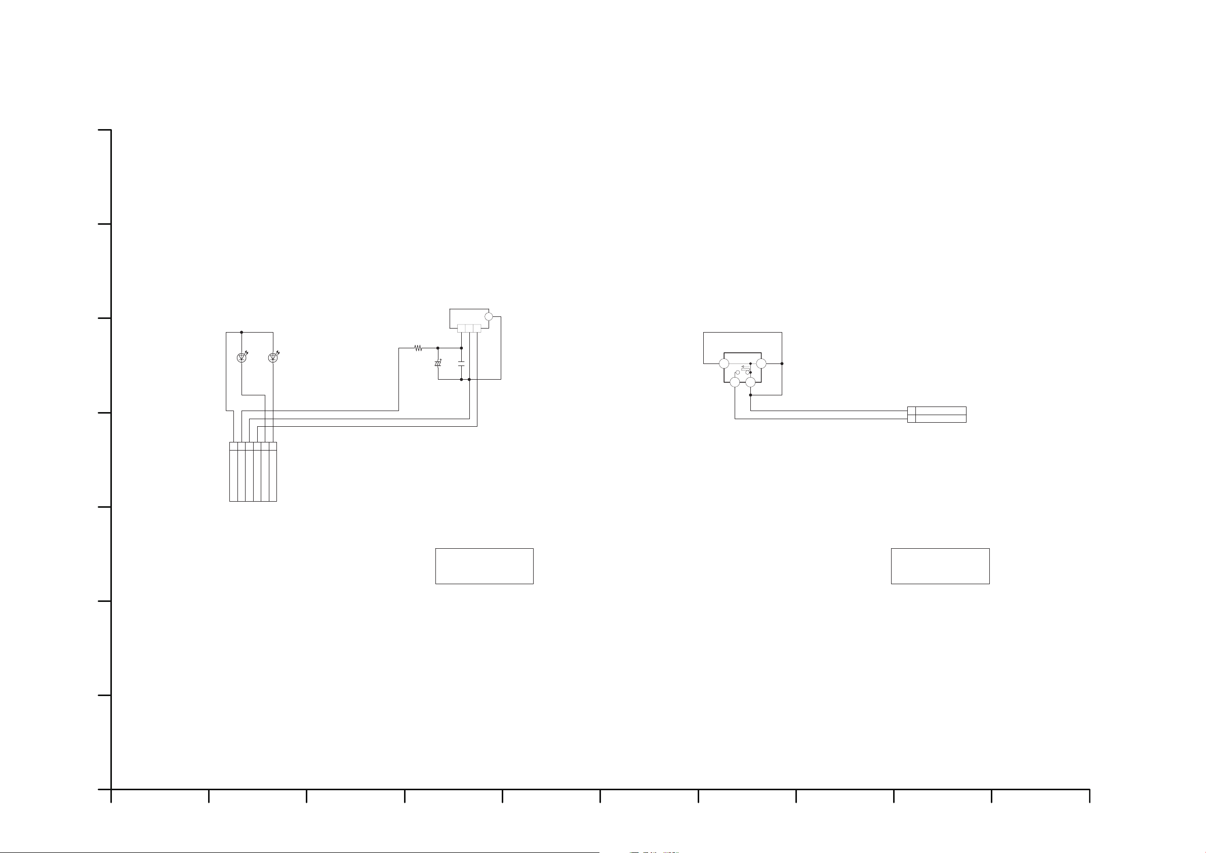
S3.5. Remote Control LED Schematic Diagram / S3.6. LCD_Angle Schematic Diagram
Confidential
Until
47
R6201
3 2 1
G1
IR6201
PNA4811M00YD
C6202
0.1
16V
C6201
F2A0J470A245
6.3V
B3AAB0000316
D6202
B3AFB0000244
D6201
1
56324
K1MN06BA0148
P6201
2009/2/28
GND
REMOCOM
PW_RTC+3R3V
CHARGE_LED
STANDBY_LED
PW_OPR+3R3V
[ES3]
DMP-B15EB/EE/EG
Remote Control LED
Schematic Diagram
10987654321
G
F
E
D
C
B
A
Confidential
Until
41
2 3
ESE31L01T
S6301
1
2
K1KA02BA0014
P6301
2009/2/28
[ES1]
GND
LCD_ANGLE
DMP-B15EB/EE/EG
LCD_Angle
Schematic Diagram
S-7
Page 39
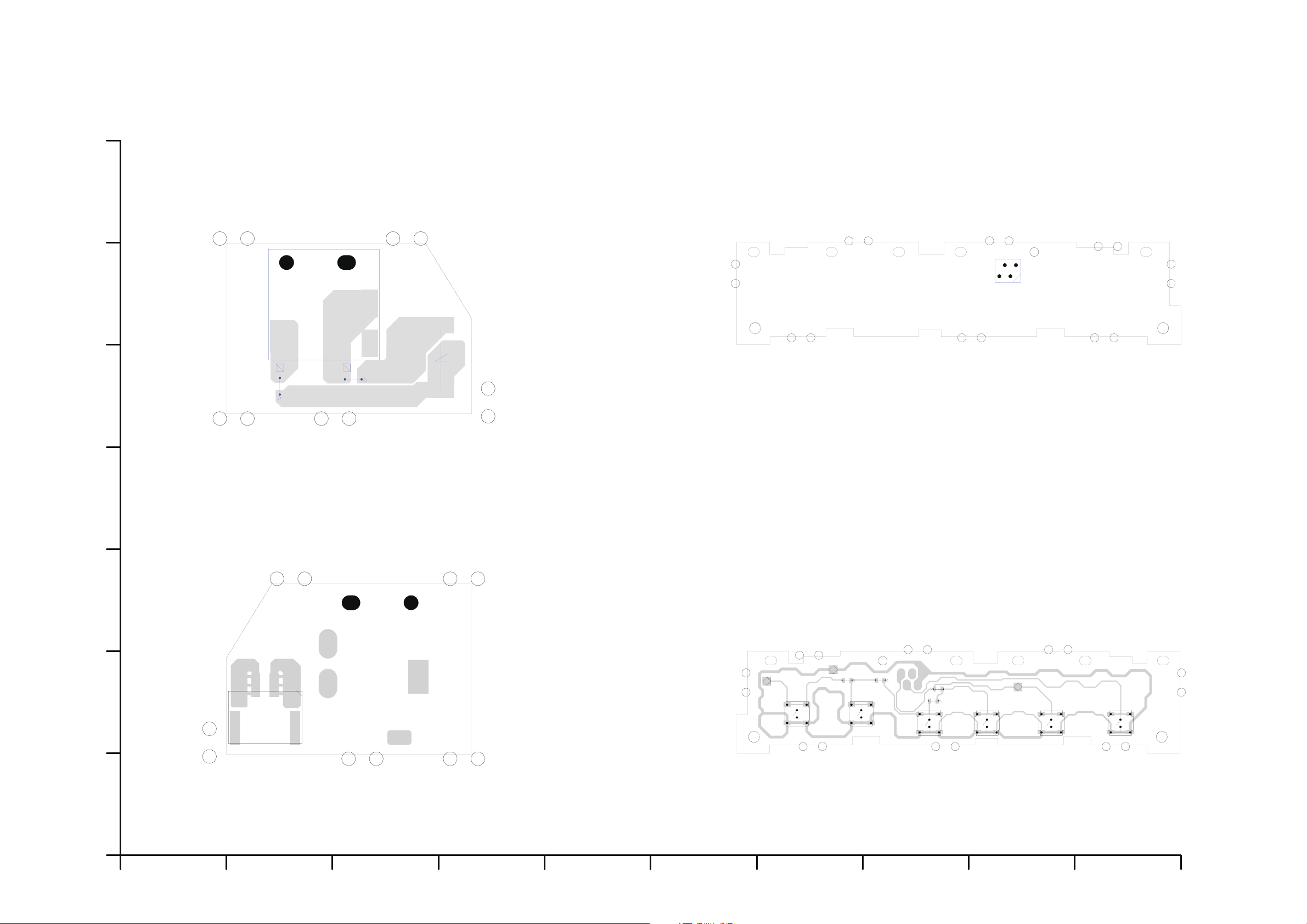
S4. Print Circuit Board
2 1
P1801
CL1802
CL1801
IP1801
IP1802
VA1801
3 2
1
JK1801
DMP-B15EB/EE/EG
DC Jack P.C.B.
TL6003
TL6002
TL6001
R6004
R6003
R6002
R6001
4
3
2
1
S6001
4
3
2
1
S6005
4
3
2
1
S6004
4
3
2
1
S6003
4
3
2
1
S6002
4
3
2
1
S6006
(Component Side)
2134
P6001
DMP-B15EB/EE/EG
SW P.C.B. 1
(Foil Side)
10987654321
G
F
E
D
C
B
A
(Foil Side)
(Component Side)
S4.1. DC Jack P.C.B. / S4.2. SW P.C.B. 1
S-8
Page 40
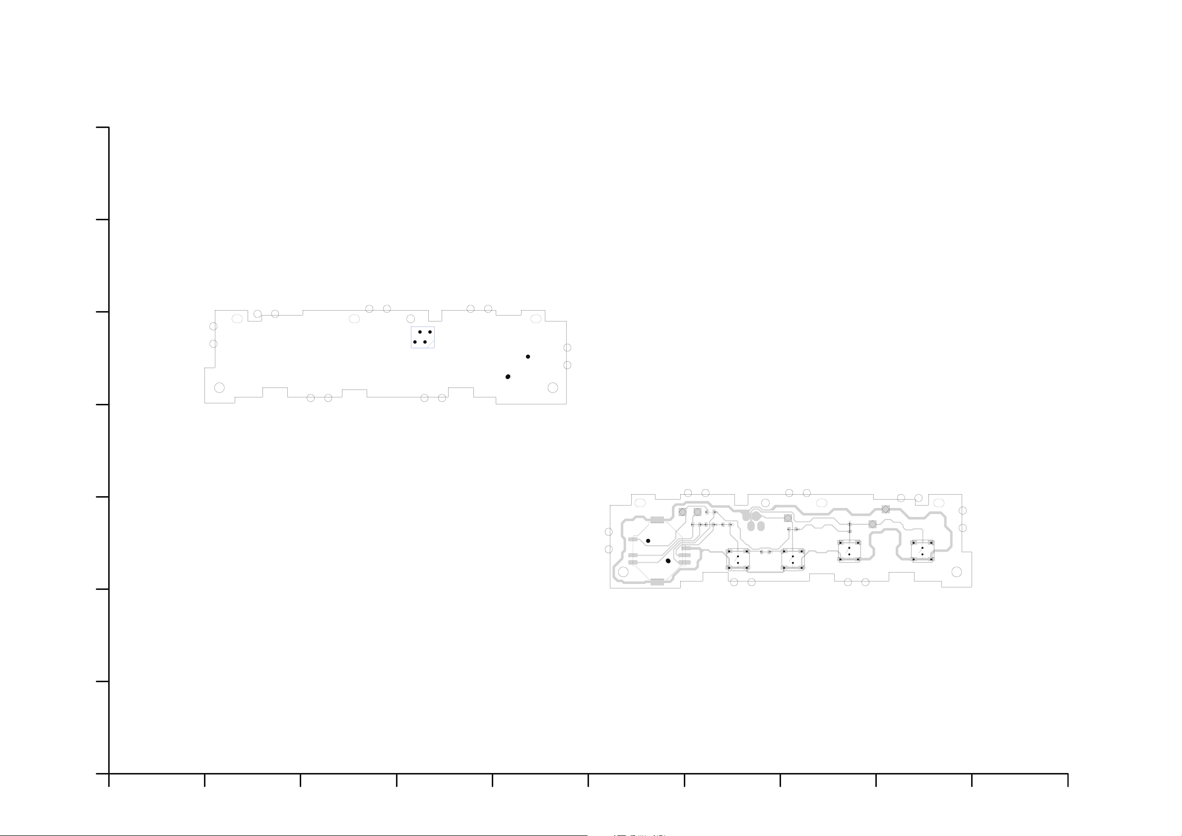
S4.3. SW P.C.B. 2
TL6105
R6107
TL6104
R6106 R6105
R6104
R6102
R6101
R6103
TL6101
TL6103
TL6102
523
6
4 1
8 7
S6105
4
3
2
1
S6104
4
3
2
1
S6103
4
3
2
1
S6102
4
3
2
1
S6101
2134
P6101
DMP-B15EB/EE/EG
SW P.C.B. 2
10987654321
G
F
E
D
C
B
A
(Foil Side)
(Component Side)
S-9
Page 41
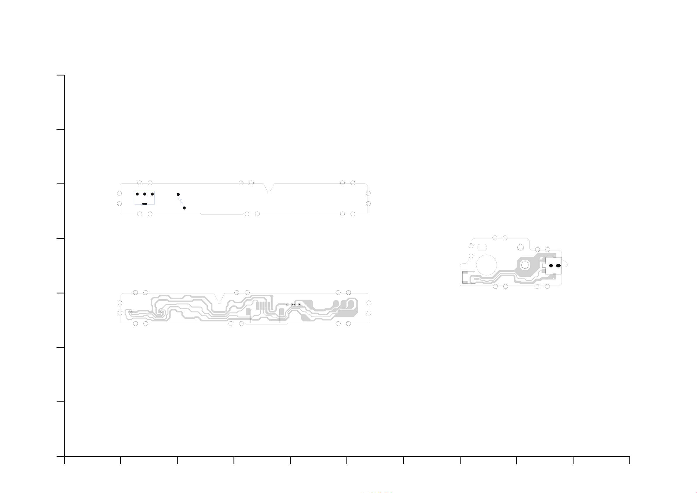
S4.4. Remote Control LED P.C.B. / S4.5. LCD Angle SW P.C.B.
4321 5 6
P6201
D6201D6202
C6202
R6201
C6201
3
1
IR6201
DMP-B15EB/EE/EG
Remote Control LED P.C.B.
4
3 2
1
S6301
1 2
P6301
DMP-B15EB/EE/EG
LCD Angle SW P.C.B.
(Foil Side)
10987654321
G
F
E
D
C
B
A
(Foil Side)
(Component Side)
S-10
Page 42

S5. Replacement Parts List
Note:
E.S.D. standards for Electrostatically Sensitive Devices, refer to “PREVENTION OF
ELECTROSTATIC DISCHARGE (ESD) TO ELECTROSTATICALLY SENSITIVE (ES) DEVICES”
section.
1.* Be sure to make your orders of replacement parts according to this list.
2. IMPORTANT SAFETY NOTICE
Components identified with the mark have the special characteristics for safety.
When replacing any of these components, use only the same type.
3. Unless otherwise specified,
All resistors are in OHMS, K=1,000 OHMS. All capacitors are in MICRO-FARADS (uf), P=uuF.
4. The marking (RTL) indicates the retention time is limited for this item. After the discontinuation
of this assembly in production, it will no longer be available.
S-11
Page 43

DMP-B15EB-
K
Ref.No. Part No. Part Name & Description Pcs Remarks Ref.No. Part No. Part Name & Description Pcs Remarks
5 RMG0775-K FOOT RUBBER 1
## VEP70296A DC JACK P.C.B. 1 (RTL) 6 RMG0775-K FOOT RUBBER 1
12 XQN17+BG8FN SCREW 1
IP1801 D1JBR015A007 IC PROTECTOR 1 13 XQN17+BG8FN SCREW 1
IP1802 D1JBR015A007 IC PROTECTOR 1 14 XQN17+BG8FN SCREW 1
15 XQN17+BG8FN SCREW 1
JK1801 K2ED2B000002 JACK,DC IN 1 16 XQN17+BG8FN SCREW 1
17 XQN17+BG8FN SCREW 1
P1801 K1KY02A00009 CONNECTOR(2P) 1 18 XQN17+BG8FN SCREW 1
19 XQN17+BG8FN SCREW 1
VA1801 ERZVF2M330 VARISTOR 1 20 XQN17+BG8FN SCREW 1
21 XQN17+BG8FN SCREW 1
22 XQN17+BG8FN SCREW 1
## VEP70275A SW P.C.B. 1 1 (RTL) 23 XQN17+BG8FN SCREW 1
24 XQN17+BG8FN SCREW 1
P6001 K1MN04AA0003 CONNECTOR(4P) 1 25 XQN17+BG8FN SCREW 1
30 RGQ0517-K1 LCD HINGE COVER 1
R6001 ERJ3GEYJ152V 1/10W 1.5K 1 39 RFKNBV100K DISC COVER ASS'Y 1
R6002 ERJ3GEYJ222V 1/10W 2.2K 1 40 RMB0897-1 DISC OPEN SPRING 1
R6003 ERJ3GEYJ332V 1/10W 3.3K 1 41 XQN17+B4FN SCREW 1
R6004 ERJ3GEYJ472V 1/10W 4.7K 1 42 XQN17+B4FN SCREW 1
43 RGL0719-W LIGHT PANEL 1
S6001 K0F111A00472 SWITCH 1 46 RDG0640 TORQUE GEAR 1
S6002 K0F111A00472 SWITCH 1 47 RMQ1695 REINFORCEMENT CHASSIS 1 1
S6003 K0F111A00472 SWITCH 1 48 RMQ1696 REINFORCEMENT CHASSIS 2 1
S6004 K0F111A00472 SWITCH 1 49 RMQ1697 REINFORCEMENT CHASSIS 3 1
S6005 K0F111A00472 SWITCH 1 50 RMQ1698 REINFORCEMENT CHASSIS 4 1
S6006 K0F111A00472 SWITCH 1 51 XQN17+BG4FNJ SCREW 1
52 XQN17+BG4FNJ SCREW 1
53 XQN17+BG4FNJ SCREW 1
## VEP70276A SW P.C.B. 2 1 (RTL) 54 XQN17+BG4FNJ SCREW 1
55 XQN17+BG4FNJ SCREW 1
P6101 K1MN04AA0003 CONNECTOR(4P) 1 56 VEP70279A LCD ANGLE P.C.B. 1 (RTL)
57 REZ1918 WIRE ROD 1
R6101 ERJ3GEYJ152V 1/10W 1.5K 1 58 RMQ1736 SPONGE 1
R6102 ERJ3GEYJ222V 1/10W 2.2K 1 61 RGU2521-KL DISC OPEN BUTTON 1
R6103 ERJ3GEYJ332V 1/10W 3.3K 1 62 RML0699A LOCK OFF LEVER 1
R6104 ERJ3GEYJ152V 1/10W 1.5K 1 63 RMB0834 OPEN BUTTON SPRING 1
R6105 ERJ3GEYJ222V 1/10W 2.2K 1 64 RFKKB15PP MAIN CABINET ASS'Y 1
R6106 ERJ3GEYJ332V 1/10W 3.3K 1 65 RKW0890-K SENSOR COVER 1
R6107 ERJ3GEYJ472V 1/10W 4.7K 1 66 RGQ0515-K3 LCD PANEL COVER 1
67 XQN17+BG6FN SCREW 1
S6101 K0F111A00472 SWITCH 1 68 XQN17+BG6FN SCREW 1
S6102 K0F111A00472 SWITCH 1 69 XQN17+BG6FN SCREW 1
S6103 K0F111A00472 SWITCH 1 70 XQN17+BG6FN SCREW 1
S6104 K0F111A00472 SWITCH 1 71 XQN17+BG6FN SCREW 1
S6105 K0C115A00002 SWITCH 1 72 XQN17+BG6FN SCREW 1
73 RGQ0516-K1 HINGE COVER 1
74 XQN17+B4FN SCREW 1
## VEP70277A REMCON/LED P.C.B. 1 (RTL)E.S.D. 75 XQN17+B4FN SCREW 1
76 XQN17+B4FN SCREW 1
C6201 F2A0J470A245 6.3V 47U 1 77 XQN17+B4FN SCREW 1
C6202 F1H1C104A071 16V 0.1U 1 78 RMA2169 HINGE FIXING PLATE 1
79 RXQ1697 HINGE 1 1
D6201 B3AFB0000244 DIODE 1 E.S.D. 80 RMA2168-1 LCD REINFORCEMENT PLATE 1
D6202 B3AAB0000316 DIODE 1 E.S.D. 81 XQN17+BG4FNJ SCREW 1
82 XQN17+BG4FNJ SCREW 1
IR6201 PNA4811M00YD REMOTE SENSOR 1 83 XQN17+BG4FNJ SCREW 1
84 XQN17+BG4FNJ SCREW 1
P6201 K1MN06BA0148 CONNECTOR(6P) 1 85 L5EDD2Q00012 LCD 1
86 RGP1395B-K3 LCD PANEL 1
R6201 ERJ3GEYJ470V 1/10W 47 1 213 RMQ1738 COPPER CHIP 1
230 RMZ1037 LCD SPACER 1
231 RMQ1746 CUSHION 1
## VEP70279A LCD ANGLE P.C.B. 1 (RTL) 232 RMQ1746 CUSHION 1
236 RMQ1739 COPPER CHIP 1
P6301 K1KA02BA0014 CONNECTOR(2P) 1 237 RMG0794-K PAD 1
239 RMF0441 SPACER 1
S6301 ESE31L01T SWITCH 1
## M2 1
## CASING/ACCESSORY/PACKING 1
7 RKA0214-K1 FOOT RUBBER 1
1 RMG0775-K FOOT RUBBER 1 8 RKA0214-K1 FOOT RUBBER 1
2 RMG0775-K FOOT RUBBER 1 9 RGQ0529-S BOTTOM COVER 1
3 RMG0775-K FOOT RUBBER 1 10 XQN17+BG4FNJ SCREW 1
4 RMG0775-K FOOT RUBBER 1 26 VEP70296A DC JACK P.C.B. 1 (RTL)
S-12
Page 44
DMP-B15EB-
K
Ref.No. Part No. Part Name & Description Pcs Remarks Ref.No. Part No. Part Name & Description Pcs Remarks
27 RFKB76189C MAIN P.C.B. 1 EB,EG (RTL)E.S.D. 189 RKA0215-K1 FOOT RUBBER 1
27 RFKB76189D MAIN P.C.B. 1 EE (RTL)E.S.D. 190 RKA0215-K1 FOOT RUBBER 1
28 RMR1899-K TRAVERSE CHASSIS 1 191 XTB2+6GJFK SCREW 1
29 VXA8630 TRAVERSE UNIT 1 192 XTB2+6GJFK SCREW 1
29-1 VMG1849 FLOATING RUBBER 1 193 XTB2+6GJFK SCREW 1
29-2 VMG1849 FLOATING RUBBER 1 194 XTB2+6GJFK SCREW 1
29-3 VMG1849 FLOATING RUBBER 1 195 XTB2+6GJFK SCREW 1
29-4 VMG1849 FLOATING RUBBER 1 196 XTB2+6GJFK SCREW 1
106 RKC0042 HINGE 2 1 197 XTB2+6GJFK SCREW 1
107 RKC0043 HINGE 3 1 198 RGQ0526-S STAND 1
108 REZ1925 WIRE ROD 1 199 RMQ1692-2 STOPPER 1
110 VEP70277A REMCON/LED P.C.B. 1 (RTL)E.S.D. 200 VSQ1088-2 MAGNET 1
111 REZ1923 WIRE ROD(4P FFC) 1 201 VSQ1088-2 MAGNET 1
112 REZ1924 WIRE ROD(4P FFC) 1 211 RGQ0527-S STAND COVER 1
113 RMQ1729 SPEAKER CUSHION (B) 1 212 REZ1943 WIRE ROD 1
114 RMQ1729 SPEAKER CUSHION (B) 1 216 RMQ1737 SPONGE 1
115 RAQ0070 SPEAKER L 1 217 RMQ1739 COPPER CHIP 1
116 RAQ0071 SPEAKER R 1 221 XQN17+BG6FN SCREW 1
117 XTN17+6GFJK SCREW 1 222 XQN17+BG6FN SCREW 1
118 XTN17+6GFJK SCREW 1 223 RMQ1716 SPONGE 1
119 XQN17+BG4FNJ SCREW 1 224 RMQ1735 SPONGE 1
120 XQN17+BG4FNJ SCREW 1 225 XTB2+6GJFK SCREW 1
121 XQN17+BG4FNJ SCREW 1 226 XTB2+6GJFK SCREW 1
122 XQN17+BG4FNJ SCREW 1 227 XTB2+6GJFK SCREW 1
123 XTN17+6GFJK SCREW 1 228 XTB2+6GJFK SCREW 1
124 XTN17+6GFJK SCREW 1 229 RMQ1748 COPPER CHIP 1
125 XTN17+6GFJK SCREW 1 233 RGN2965B-H1 NAME LABEL 1 EB,EG
126 XTN17+6GFJK SCREW 1 233 RGN2965D-H2 NAME LABEL 1 EE
127 VEP70275A SW P.C.B. 1 1 (RTL) 235 RQLS0412 CAUTION LABEL 1
128 VEP70276A SW P.C.B. 2 1 (RTL) 238 RMG0797-K SPACER 1
129 RGU2623A-S BUTTON 1 240 RMF0439 SPACER 1
130 RGU2624B-S BUTTON 1 241 RFKNB15EB TRV/MAIN P.C.B. 1 EB E.S.D.
131 RGU2626-S JOYSTICK BUTTON 1 241 RFKNB15EE TRV/MAIN P.C.B. 1 EE E.S.D.
132 RMZ0993 INSULATION SHEET 1 241 RFKNB15EG TRV/MAIN P.C.B. 1 EG E.S.D.
133 RSC0861 SHIELD PLATE 1
134 RMN0920 AC JACK COVER 1
135 XQN17+BG4FNJ SCREW 1 ## M3 1
136 XQN17+BG4FNJ SCREW 1
137 XQN17+BG4FNJ SCREW 1 A1 RFEA219W-AA AC ADAPTOR 1
138 XQN17+BG4FNJ SCREW 1 A2 N2QAJC000016 REMOTE CONTROL 1
139 XQN17+BG4FNJ SCREW 1 A2-1 RM36FWA01 BATTERY COVER 1
140 XTN17+6GFJK SCREW 1 A3 K2CQ2CA00006 AC POWER SUPPLY CORD 1 EG,EE
141 XTN17+6GFJK SCREW 1 A3 K2CT3CA00004 AC POWER SUPPLY CORD 1 EB
142 XTN17+6GFJK SCREW 1 A4 K2KC4CB00026 AUDIO/VIDEO CABLE 1
143 XTN17+6GFJK SCREW 1 A5 RQT9335-D OPERATING INSTRUCTIONS 1 EG
144 RMQ1747 CONDUCTION CUSHION 1 A5 RQT9338-B OPERATING INSTRUCTIONS 1 EB,EG
145 RSC0863 SHIELD SHEET 1 A5 RQT9339-R OPERATING INSTRUCTIONS 1 EE
146 RMQ1715 CONDUCTION CUSHION 1 A5 RQT9336-E OPERATING INSTRUCTIONS 1 EG
147 RMQ1715 CONDUCTION CUSHION 1 A6 RFE0215 CLEANING CLOTH 1
148 RMQ1715 CONDUCTION CUSHION 1 A8 RPFC0031-B POLYETHYLENE BAG 1
149 RMQ1715 CONDUCTION CUSHION 1 A9 RFEC206P-Y CAR DC ADAPTOR 1
150 RSC0873 HEAT RADIATION PLATE 1 1 A10 RXQ1706 HEADREST MOUNTING BRACKET 1
151 RSC0874 HEAT RADIATION PLATE 2 1 A11 RFC0150-K SAFETY BELT 1
152 RSC0875 HEAT RADIATION PLATE 3 1
161 XQN2+B3FN SCREW 1 PC1 RPFC0104 POLYETHYLENE BAG(UNIT) 1
162 XQN2+B3FN SCREW 1 PC2 RPN2096A PAD (A) 1
165 RMY0387 HEAT RADIATION PLATE 4 1 PC3 RPN2096B PAD (B) 1
166 XQN17+BG4FNJ SCREW 1 PC4 RPQF0334 ACCESSORY BOX 1
167 XQN17+BG6FN SCREW 1 PC5 RPK2794 PACKING CASE 1 EG
168 XQN17+BG6FN SCREW 1 PC5 RPK2796 PACKING CASE 1 EE
169 XQN17+BG6FN SCREW 1 PC5 RPK2795 PACKING CASE 1 EB
170 XQN17+BG6FN SCREW 1
171 XQN17+BG6FN SCREW 1
172 XQN17+BG6FN SCREW 1
173 XQN17+BG6FN SCREW 1
174 XQN17+BG6FN SCREW 1
175 RSC0893 CONDUCTION CUSHION 1
176 RMA2032 REINFORCEMENT PLATE 1
177 RMA2032 REINFORCEMENT PLATE 1
178 RGQ0520-S HINGE COVER 1
179 RGQ0521-S HINGE COVER 1
180 RGQ0521-S HINGE COVER 1
183 RMS0870 SD SHAFT 1
184 RKF0841-S SD CARD COVER 1
185 RGQ0523-S SHAFT 1
186 RMC0626-1 SD SPRING 1
188 RKS0455B-S BOTTOM CABINET 1
S-13
Page 45
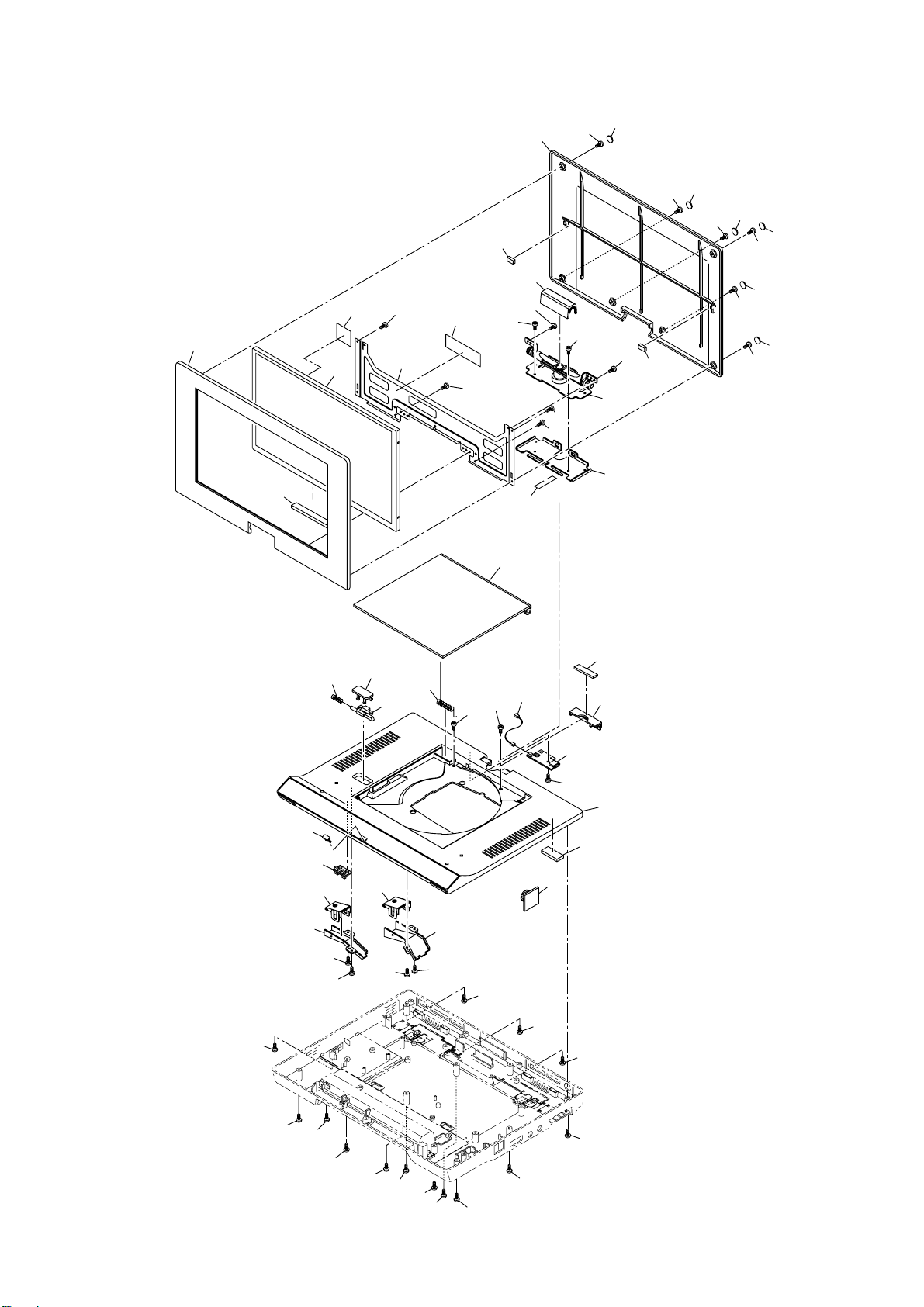
S6. Exploded View
S6.1. Frame and Casing Section (1)
236
86
85
230
81
80
239
82
231
39
76
73
75
213
66
84
83
67
77
79
78
1
2
68
3
69
4
70
5
71
74
232
6
72
12
65
48
43
50
51
63
52
61
49
53
62
40
54
47
41
13
42
57
237
30
56
55
64
58
46
14
15
25
17
24
23
22
19
21
16
18
20
S-14
Page 46
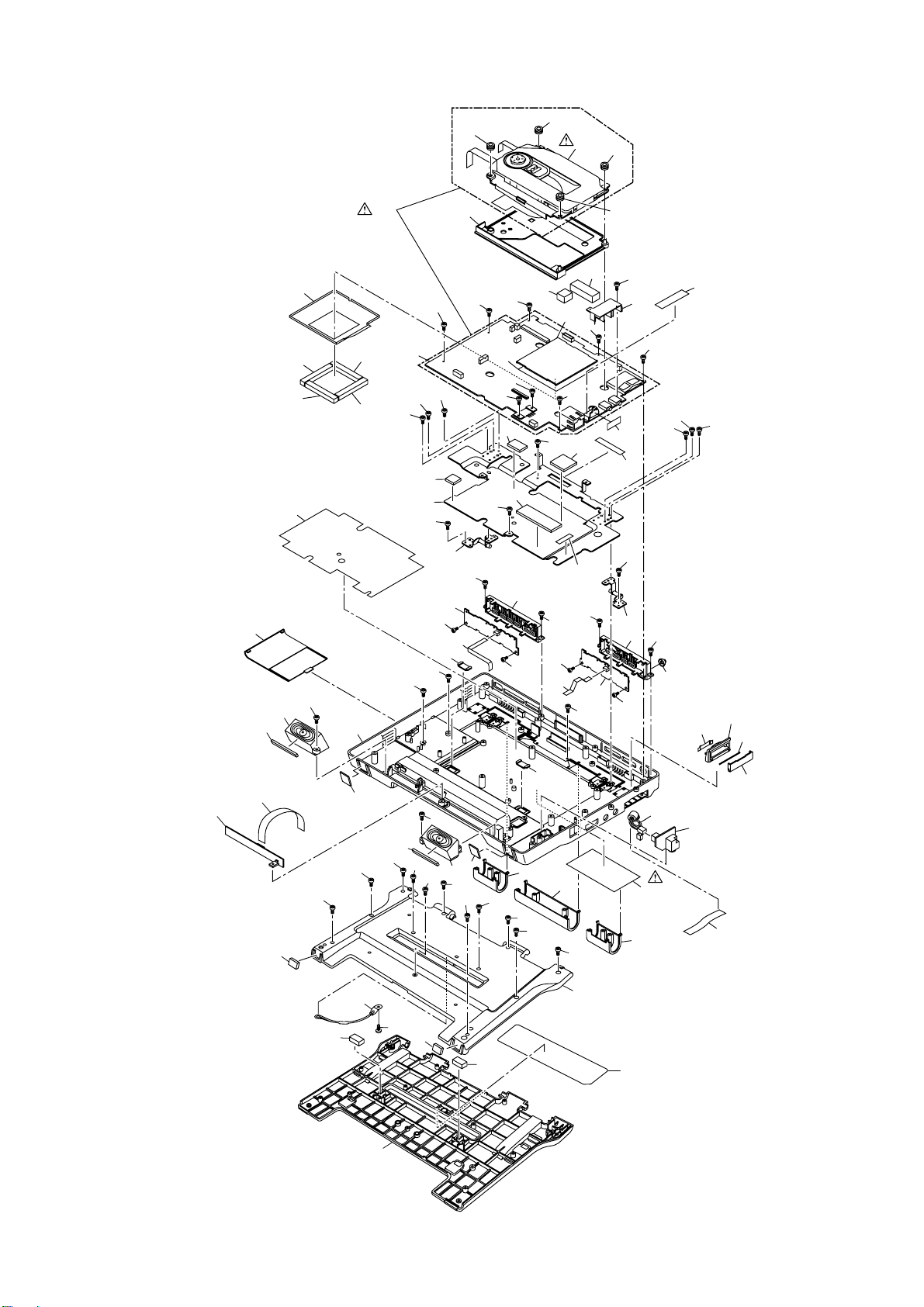
S6.2. Frame and Casing Section (2)
9
113
115
145
147
149
175
117
188
146
148
241
161
168
27
167
165
238
221
169
139
173
126
176
107
127
111
29-3
28
119
143
166
138140
132
142
151
152
129
125
224
29-2
133
171
120
124
112
137
135
150
217
121
29
172
223
128
29-1
29-4
141
134
144
216
222
106
130 122
123
136
162
170
131
229
186
174
185
183
110
108
189
191
200
192
199
177
7
118
114
193
211
10
194
195
190
116
196
197
8
180
178
225
226
227
228
198
201
212
26
235
179
233
184
240
S-15
Page 47
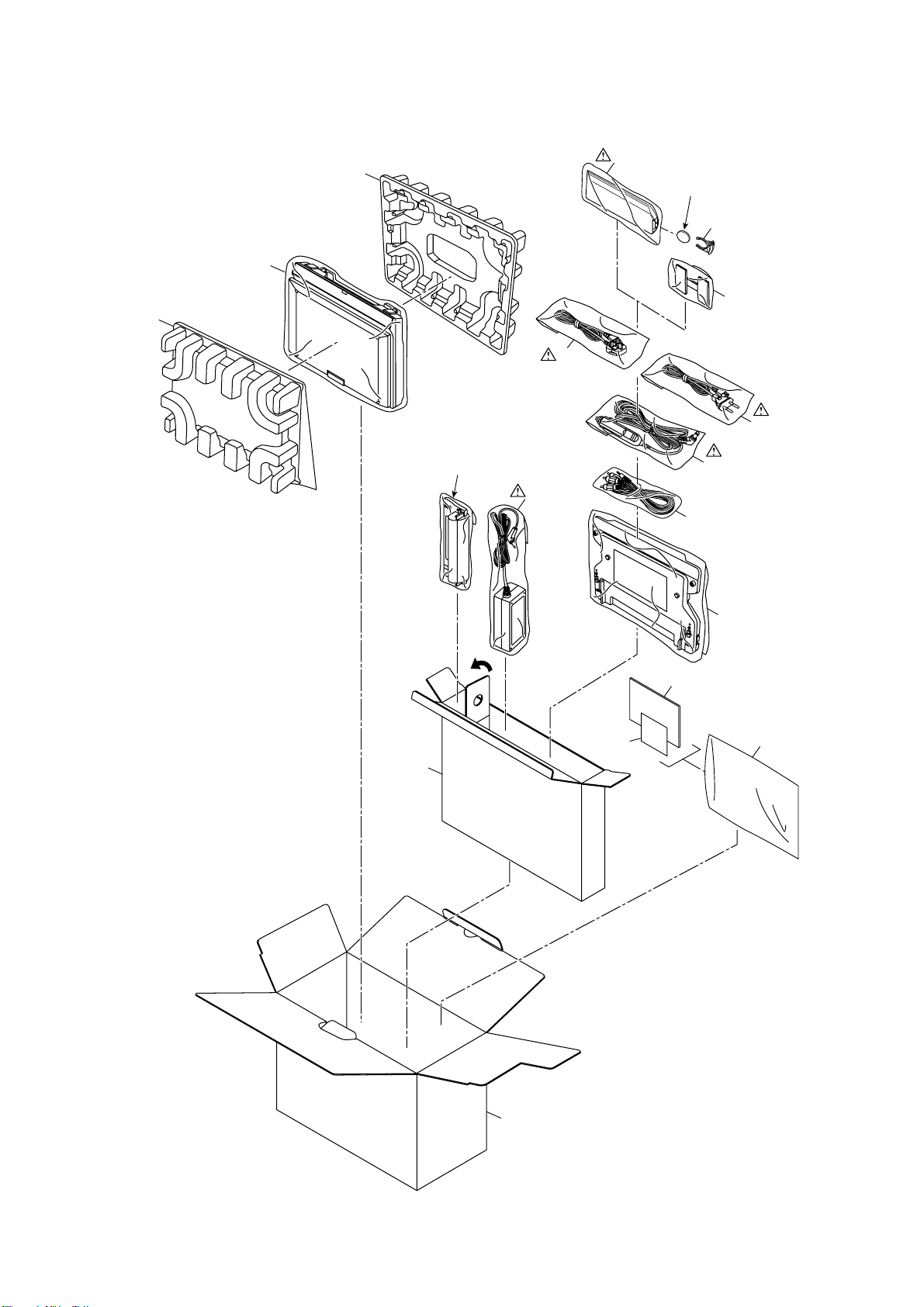
S6.3. Packing Parts and Accessories Section
PC2
PC1
PC3
Rechargeable battery pack
(Available on sales route)
(DMP-B15EB)
A3
A1
A2
Button-type battery
(Available on sales route)
A2-1
A11
(DMP-B15EE/EG)
A3
A9
A4
PC4
A6
A10
A5
A8
S-16
PC5
 Loading...