

Page 1
ORDER NO. CPD0604067C1
Personal Computer
CF-T4
This is the Service Manual for
the following areas.
M …for U.S.A. and Canada
Model No. CF-T4HWETZBM
© 2006 Matsushita Electric Industrial Co., Ltd. All rights reserved.
Unauthorized copying and distribution is a violation of law.
Page 2

CONTENTS
Page Page
1 Read Me First. ...................................................................
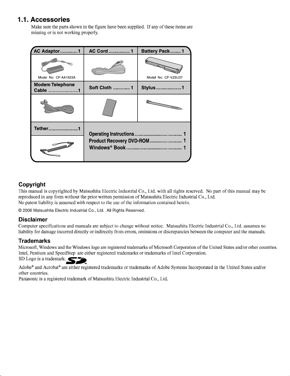
1.1 . Accessories .............................................................
2 Specifications ..................................................................
3 Names and function of Parts ..........................................
4 Diagnosis & Repair ..........................................................
4.1. Basic Procedures .....................................................
4.2. Troubleshooting .......................................................
4.3. Connection Diagram ................................................
4.4. Power-on Self Test (Boot Check) .............................
5 Self Diagnosis Test ..........................................................
5.1. Outline of Self Diagnostic Test .................................
5.2. Automatic Test ..........................................................
5.3. Peripheral Test .........................................................
5.4. Test Selection ...........................................................
5.5. Error Messages and Troubleshooting ......................
9
10
11
12
12
13
19
20
22
22
23
24
25
26
6 Disassembly & Reassembly Instruction ...................
4
6.1. Disassembly Flow Chart .....................................
6.2. Disassembly ........................................................
6.3. Reassembly ........................................................
7 Explanation of Hardware ............................................
7.1. System Block Diagram ........................................
8 Main Unit Extended View ...........................................
8.1. Display section ....................................................
8.2. Cabinet section ...................................................
8.3. Bottom section ...................................................
9 Replacement Parts List ..............................................
27
27
28
35
43
43
45
45
47
48
49
2
Page 3
34567
Page 4
Page 5
Page 6
Page 7
Page 8
8
Page 9
9
Page 10
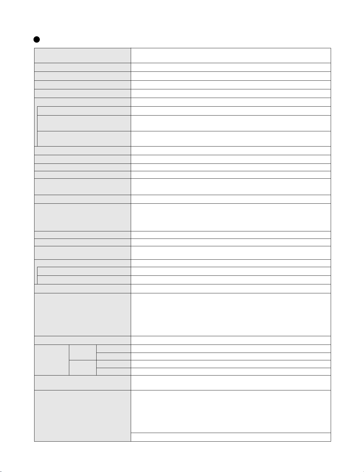
2. Specifications
Main Specifications
CPU/
Secondary cache memory
Chip Set
Main Memory
Video Memory
Hard Disk Drive (Replaceable)
Display Method
Internal LCD Display
*
External Display
5
Simultaneous Display on LCD + Exter-
*
nal Display
5
Wireless LAN
*
6
LAN
®
Intel
Pentium® M Processor Ultra Low Voltage 753 (1.20 GHz, 2 MB
MHz FSB)
®
Intel
915 GMS Express chip set
*
512 MB
1
, DDR2 SDRAM (1024 MB
UMA (128 MB
*3
60 GB
*
1
Max.)
*2
*
1
Max.)
12.1 XGA type (TFT) (1024 × 768 dots)
*
65,536/16,777,216 colors (1024
× 768 dots)
4
65,536/16,777,216 colors (800 × 600 dots/1024 × 768 dots/1280 × 768 dots/1280 ×
1024 dots/1600 × 1200 dots/2048 × 1536 dots)
*
65,536/16,777,216 colors (800 × 600 dots, 1024 × 768 dots)
Built-in Intel
®
PRO/Wireless 2915 ABG
4
IEEE 802.3 10Base-T, IEEE 802.3u 100Base-TX
Modem Data: 56 kbps (V.92) FAX: 14.4 kbps
Sound WAVE and MIDI playback, Monaural Speaker (built in)
Card Slots
RAM Module Slot
Interface
PC Card Slot × 1: (One Type I or Type II, Allowable current 3.3 V: 400 mA, 5 V: 400 mA)
*
SD Memory Card Slot
7
× 1
DDR2 SDRAM, 172-pin, 1.8 V, Micro DIMM, PC2-3200 Compliant
*
USB Ports × 2 ( USB2.0 × 2 )
9
/ Modem Port ( RJ-11 ) / LAN Port ( RJ-45 )
External Display Port: Mini Dsub 15-pin female / Microphone Jack: Miniature jack, 3.5
DIA / Headphone Jack: Miniature jack, 3.5 DIA / Mini Port Replicator connector: Dedicated 50-pin male
Keyboard/Pointing Device 83 keys/Touch Pad/Touchscreen (stylus (included) touch capable)
Power AC adaptor or Battery pack
AC Adaptor
*
10
Input: 100 V - 240 V AC, 50 Hz/60 Hz
Output: 16 V DC, 2.5 A
Battery Pack Li-ion 11.1 V, 7.65 Ah
*
Operating Time
Charging Time
11
*
14
Power Consumption
Approx. 6 hours -12 hours
Approx. 5 hours (Power off)/Approx. 7 hours (Power on)
*
15
Approx. 35 W
*
16
/ Approx. 40 W (maximum when recharging in the ON state)
*
12
(Approx. 8 hours
*
13
) (Disable Economy mode (ECO))
•Including protrusion of the hand strap
268 mm × 28.1 mm (at the front)/66.9 mm (at the rear) × 210 mm
Physical Dimensions (W × H × D)
(excluding the stylus holder)
*
17
Weight
Te mperature
Humidity 30% to 80% RH (No condensation)
Te mperature
Humidity 30% to 90% RH (No condensation)
Environment
*
18
OS
Operation
Storage
{10.6 " × 1.1 " /2.7 " × 8.3 "}
•Excluding protrusion of the hand strap
268 mm
{10.5 "
× 28.1 mm (at the front)/49.1 mm (at the rear) × 210 mm
× 1.1 " /2.0 " × 8.3 "}
Approx. 1520 g {3.4 lb.} (including the stylus)
5°C to 35°C {41°F to 95°F}
-20°C to 60°C {-4°F to 140°F}
Microsoft® Windows® XP Professional with Service Pack 2 with Advanced Security
Te chnologies (NTFS File system)
Microsoft® Internet Explorer 6 Service Pack 2 / DirectX 9.0 c / Microsoft® Windows®
Media Player 10 / Microsoft® Windows® Movie Maker 2.1 / Microsoft® .NET Framework
1.1 / Adobe Reader / Intel® PROSet/Wireless Software / SD Utility / Icon Enlarger /
Loupe Utility / Touch Pad Utility / DMI Viewer / PC Information Viewer / Display Rotation
Pre-installed Software
*
18
To ol / Hotkey Settings / Wireless LAN Switch Utility / Economy Mode (ECO) Setting Utility / Battery Recalibration Utility / Infineon TPM Professional Package*
*
Setup Utility / Hard Disk Data Erase Utility
19
/ Hard Disk Backup Utility
*
1
L2 cache, 400
*
8
20
*
19
*
6
/
10
Page 11
*1
1 MB = 1,048,576 bytes
*2
A segment of the main memory is allotted automatically depending on the computer ’s operating status. The size of the Video
Memory cannot be set by the user.
*3
1 GB = 1,000,000,000 bytes. Operating system or some application software will report as fewer GB.
*4
A 16,777,216 color display is achieved by using the dithering function.
*5
Display may be impossible using some connected external displays.
*6
Some devices cannot be used depending on the port type.
*7
Operation has been confirmed for Panasonic SD memory cards with up to 2 GB capacity. The transfer rate using the SD memory
card slot on this computer is 8 MB per second (this is a theoretical value, and differs from actual speeds). The transfer rate is 8
MB per second even if you use an SD memory card that supports high-speed transfer rates. Does not guarantee connection/
operation of all SD devices. Does not support MultiMedia card. Do not insert MultiMedia card.
*8
Only a RAM module designed for DDR2 (PC2-3200) can be added (Panasonic : CF-BAV0256U / CF-BAV0512U).
JEDEC standard 214 pin Micro DIMM cannot be used. PC2100 / PC2700 172 pin Micro DIMM cannot be used.
*9
Does not guarantee operation of all USB-compatible peripherals.
*10
<Only for North America>
The AC adaptor is compatible with power sources up to 240 V AC adaptor. This computer is supplied with a 125 V AC compatible AC cord.
*11
Varies depending on the usage conditions, CPU speed, etc. Measured value when the power saving function on the USB2.0 USB
Root Hub is set to on. (At the time of purchase, the power saving function is set to off.
When Economy Mode (ECO) is enabled, the operating time becomes approximately 20% shorter than when it is disabled.
*12
Measured using BatteryMark™ Version 4.0.1 (LCD brightness : Maximum - Minimum).
*13
Measured using MobileMark™ 2002 (LCD brightness : 60 cd/m2).
*14
Varies depending on the usage conditions, CPU speed, etc.
It may take a long time to charge a fully discharged battery.
*15
Approx. 1.5 W when the battery pack is fully charged (or not being charged) and the computer is off.
*16
Rated power consumption.
*17
Average value. May differ depending on models.
*18
Operations of this computer are not guaranteed except for the pre-installed OS.
*19
The Product Recovery DVD-ROM is required.
*20
For information on TPM, input [c:\util\drivers\tpm\README.pdf] in [start] - [Run] and refer to the installation manual of “Trusted
Platform Module (TPM)”. You need to install Infineon TPM Professional Package to use TPM.
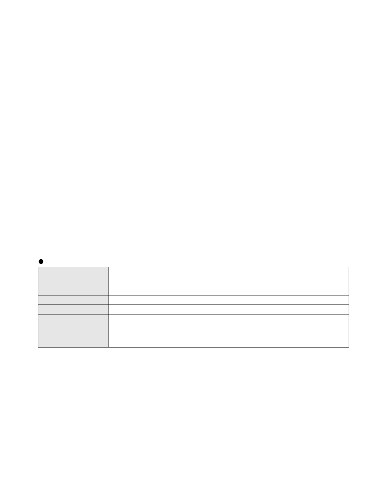
Wireless LAN
IEEE802.11a: 54/48/36/24/18/12/9/6 Mbps (automatically switched)
Data Transfer Rates
IEEE802.11b: 11 /5.5/2/1 Mbps (automatically switched)
IEEE802.11g: 54/48/36/24/18/12/9/6 Mbps (automatically switched)
Standard SupportedIEEE802.11a/IEEE802.11 b/IEEE802.11g
Transmission Method OFDM system, DS-SS system
Wireless Channels Used
RF Frequency Band
*21
These are speeds specified in IEEE802.11 a+b+g standards. Actual speeds may differ.
IEEE802.11a: Channels 36/40/44/48/52/56/60/64/149/153/157/161/165
IEEE802.11b/ IEEE802.11g: Channels 1 to 11
IEEE802.11a: 5.18 - 5.32 GHz, 5.745 - 5.825 GHz
IEEE802.11b/ IEEE802.11g: 2412 - 2462 MHz
*
21
*
20
*
21
10-1
Page 12
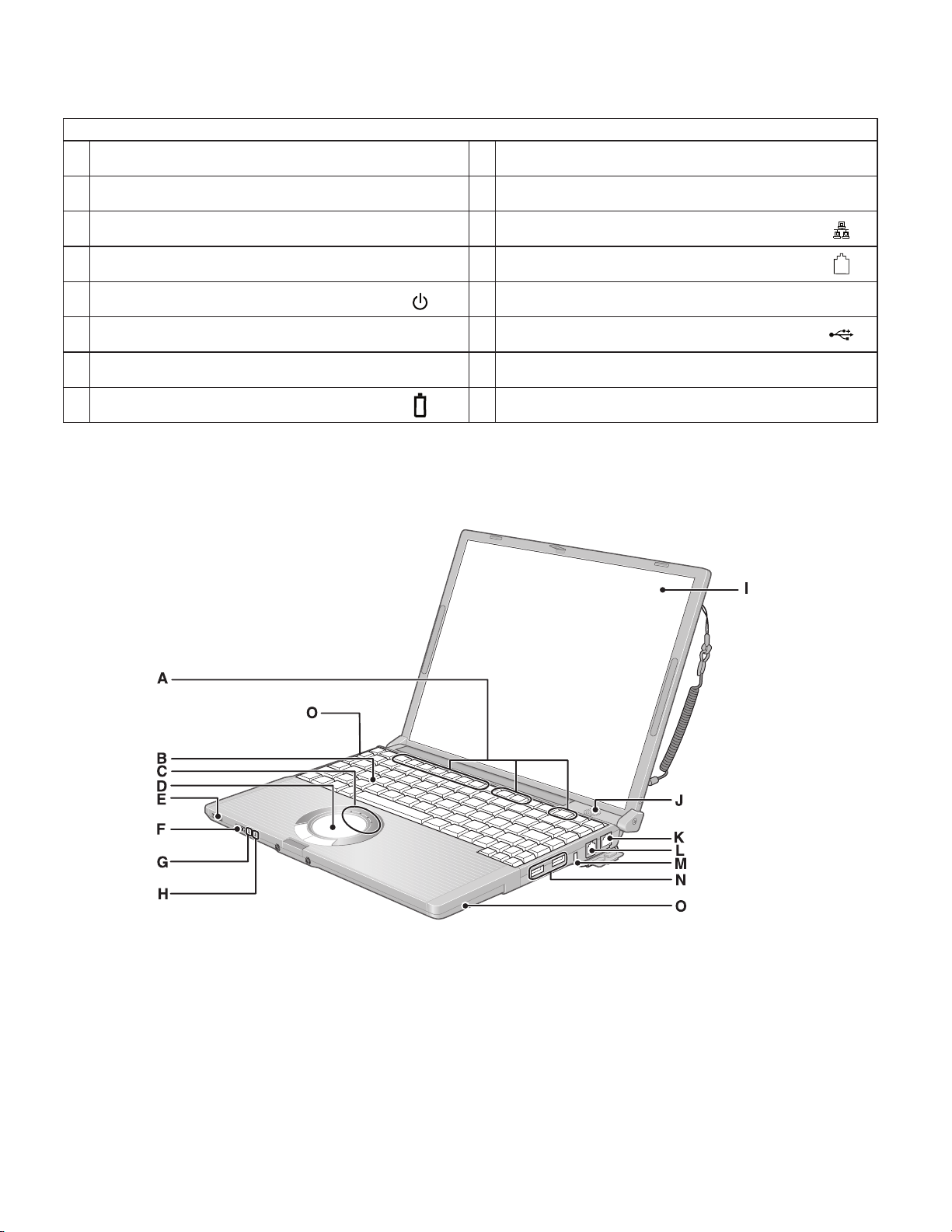
3. Names and Function of Parts
Names
A Function key I Display (internal LCD/Touchscreen)
B Keyboard J Speaker
C LEDs K LAN Port
D Touch pad L Modem Port
E Power switch/Power indicator M Security lock
F Wireless LAN switch M USB Ports
G Economy-mode (ECO) indicator O Wireless LAN Antenna (built-in)
WIRELESS LAN
ECO
H Battery indicator
11
Page 13
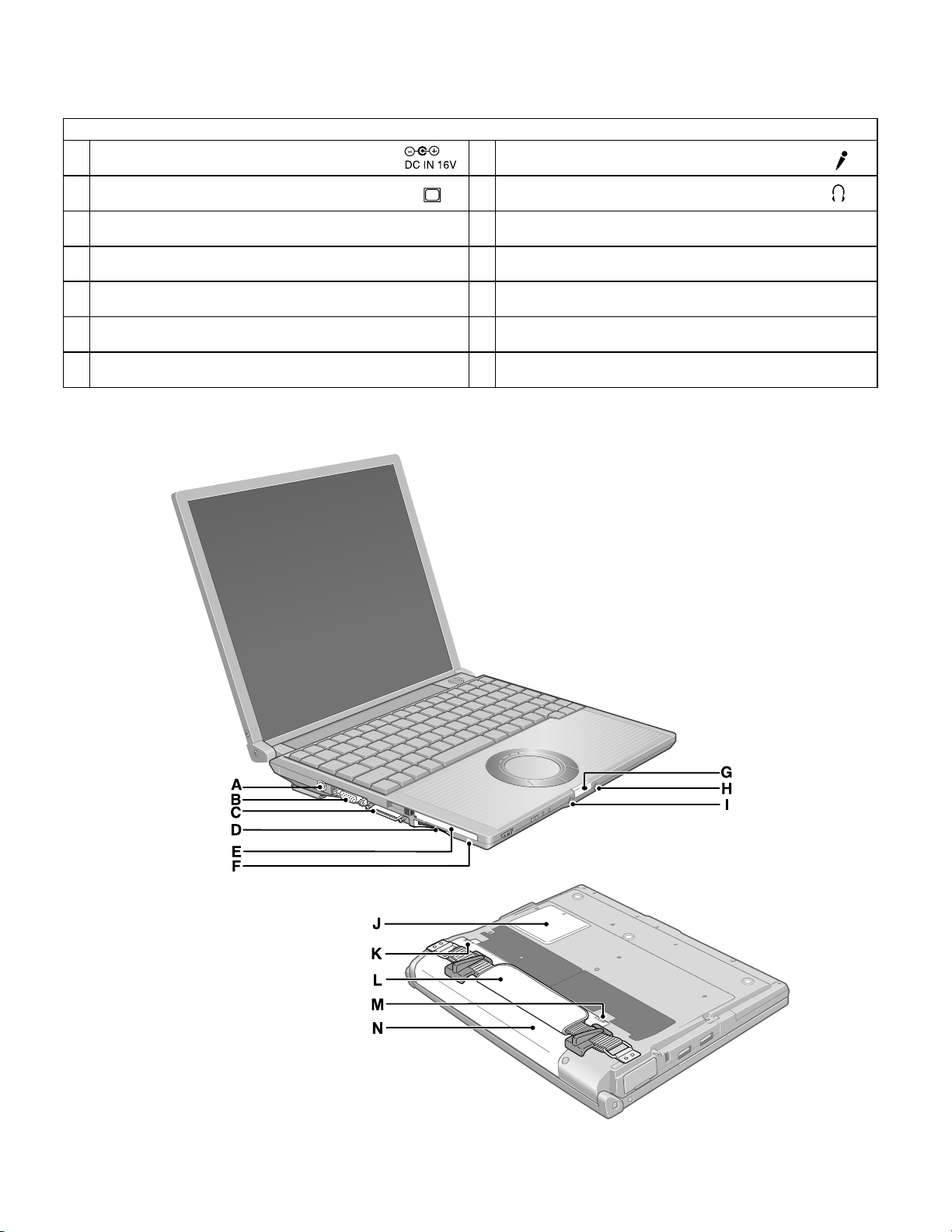
Names
A DC-IN Jack
B External Display Port
C Mini Port Replicator Connector
D SD Memory Card Slot
E PC Card Slot
F
SD Memory Card Indicator
G Latch
EXT.
H Microphone Jack
I Headphone Jack
J RAM Module Slot
K Latch
L Hand strap
M Latch
N Battery Pack
11-1
Page 14
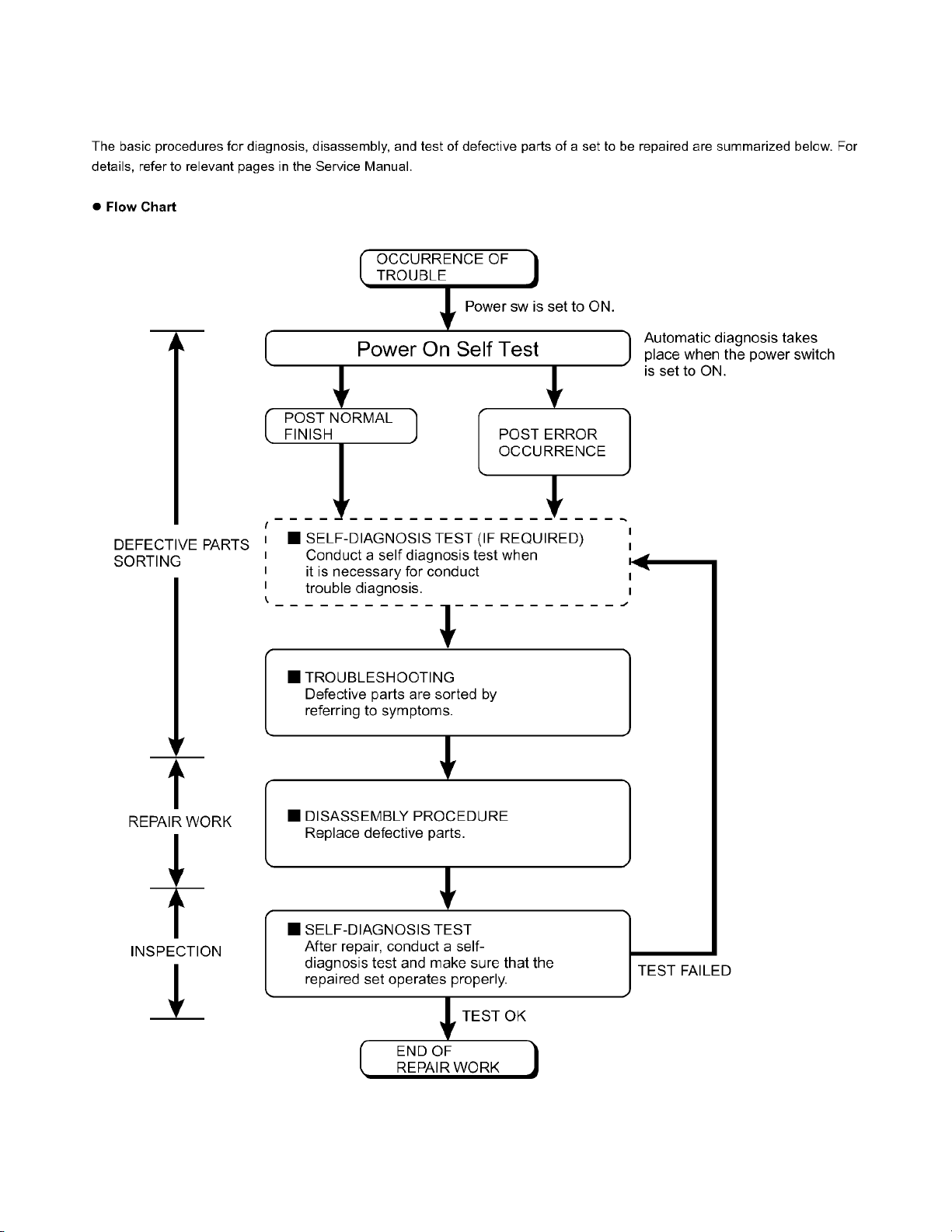
4 Diagnosis & Repair
4.1. Basic Procedures
12
Page 15
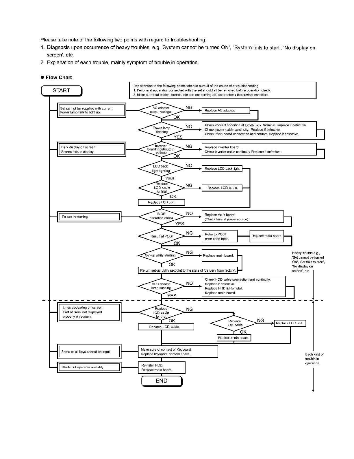
4.2. Troubleshooting
13
Page 16
Page 17
Page 18

Page 19

Page 20

ServerBIOS2 test error: Cannot write to extended DMA (Direct Memory Access) registers.
ServerBIOS2 test error: Cannot generate software NMI (Non-Maskable Interrupt).
ServerBIOS2 test error: Fail-Safe Timer takes too long.
Page 21

4.3. ConnectionDiagram
LCD/Touch Panel
LCD Back Light
Inverter Board
Connection by Cable
Direct connection Connectors
Parts on Bottom Side
Antenna Board
(R)
1
Battery Pack
LAN Module
4
Wireless
3
Antenna Board
(L)
Connection Cable
1 LCD/TP Cable DFJS963ZA
2 Speaker Cable DFJS962ZA
3 Antenna PCB-L N1ZYYY000002
4 Antenna PCB-R N1ZYYY000003
5 Modem Cable DFJS973ZA
6 LAN Cable DFJS958ZB
7 PAD FFC DFJK12U112BB
8 HDD FPC Unit DL3UP1443AAA
9 DC-IN Cable DFJS961ZB
10 Main-Sub Cable DFJS980ZA
2
Speaker
Keyboard
DC-IN
MODEM
SD Card
PCMCIA
SLOT
CN601
CN26
CN12
CN10
CN600
CN22
CN18
CN11
CN13
SW6
POWER SW
Main Board
CN2
CN19
CN14
CN16
JK2
Headphone
VGA
9
5
CN24
CN23
CN3
CN21
CN15
CN4
JK1
Mic
Lithium Battery
HDD
8
10
CN1051
CN1053
USB
CN1052
USB
7
DIMM memory
(Option)
CF-BAV0256U
CF-BAV0512U
LAN
19
6
Touch Pad
Page 22

4.4. Power-on Self Test (Boot Check)
4.4.1. Outline of POST
4.4.2. Error Diagnosis by Checking Beep Signal Sound
20
Page 23

4.4.3. Diagnosis by Error Code
Error code Message Error Description Possible faulty part
0200 Failure Fixed Disk Fixed disk in not working or not configured properly. HDD
0211 Keyboard error Keyboard not working. Confirm the keyboard is connected Keyboard
0212 Keyboard Controller Failed Keyboard controller failed test. Main board
0230 System RAM Failure System RAM failure at offset
at offset :
0231 Shadow RAM Failure Shadow RAM failure at offset
at offset :
0232 Extended RAM Failure Extended memory not working or not configured properly Main board
at offset :
0250 No battery on the system CMOS backup battery exhausted. Lithium battery
0251 System CMOS checksum System CMOS has been corrupted or modified incorrectly, Incorrect Setup
bad perhaps by an application program that changes data Lithium battery
-Default configuration used stored in CMOS.
0260 System timer error The timer test failed. Requires repair of system board. Main board
0270 Real time clock error Real-time clock fails BIOS test. May require board repair. Main board
0271 Check date and time Incorrect date and time on the system. Incorrect Setup
settings Set the correct date and time using the setup utility.
0280 Previous boot incomplete Previous POST did not complete successfully. Boot-up failure
-Default configuration used POST loads default values and offers to run Setup.
02D0 System cache error CPU trouble. Main board
-Cache disabled
02F5 DMA Test Failed Server BIOS2 test error: Cannot write to extended DMA Main board
nnnn
nnnn
nnnn
Run the Setup Utility and check that the hard disk Main board
capacity is displayed at [Primary Master].
If the [None] is displayed, disk error is occurred.
to the computer and that a key is not being held down.
May require replacing keyboard controller.
nnnn
of the 64k block at Main board
which the error was detected. If you installed RAM module,
remove the RAM module and reinstall it.
nnnn
of the 64k block at Main board
which the error was detected. If you installed RAM module,
remove the RAM module and reinstall it.
at offset
Battery replacement is required.
The BIOS installed Default SETUP Values. If you do not
want these values, enter Setup and enter your own values.
If the error persists, check the system battery or contact
Panasonic.
If the failure was caused by incorrect values and not
corrected, the next boot will likely fail.
nnnn.
Extension memory
21
Page 24

5. Self Diagnosis Test
1. Floppy disk is included for the self-diagnostic tests that should be performed before using this product.
2. Connect External Floppy Disk Drive (FDD) to USB port for diagnosis test.
Important notice
System password
This product has a password function. If this function is turned on, the self-diagnostics tests will not work.
You will need ask the user for the password before performing the self-diagnostics.
5.1. Outline of Self Diagnostic Tests
Insert the diagnostics floppy disk
● Starting up the setup utility
① Turn on the power.
② When "Panasonic Press F2 to enter setup" appears
on the screen, press F2.
Return the setup
contents to default
③ Press "→" to select 「Exit」
④ Press "↓" to select 「Get default value」
⑤ Press Enter.
⑥ Choose Yes for "Load default Configuration now?"
⑦ Select "Save Values & Exit" and press Enter.
⑧ Choose Yes for "Save Configuration changes and exit now?"
and press Enter.
Choose test from
the menu screen
to start the test.
Caution:
After completing repairs, be sure
to carry out the Automatic test
and Peripheraltest.
<Automatic test>
Tests selected (O) from the test
item list will be performed in
succession.
1. DIAG on FD
● Menu Screen 1
1. DIAG on FD
2. LAN test
3. SD I/F test
4. Modem test
5. Wireless LAN test (Wireless LAN Model only)
Q. Quit
Select please [1, 2, 3, 4, 5, Q]?
<Peripheral test>
The parallel devices can be tested.
2. LAN test
3. SD I/F test
4. Modem test
5. Wireless LAN test
(Wireless LAN Model only)
<Test selection>
Specifc tests required can
be freely selected and
performed from the test item
list.
Be sure to carry out the Selection
test only when necessary.
Problems in the unit are located and divided according
to error messages that occur during testing.
22
Page 25

1. DIAG on FD
2. LAN test
3. SD I/F test
4. Modem test
5. Wireless LAN test (Wireless LAN Model only)
Q. Quit
Select please [1, 2, 3, 4, 5, Q]?
menu screen
Page 26

Page 27

1. DIAG on FD
2. LAN test
3. SD I/F test
4. Modem test
5. Wireless LAN test (Wireless LAN Model only)
Q. Quit
Select please [1, 2, 3, 4, 5, Q]?
menu screen
2. When A:\DIAG appears, input "JDG_T4H, EXE" and press Enter.
Page 28

Order of test flow selection
Input screen startup
1. Reading the test conditions settings file
Press "ALT" and "F".
2
Press "L".
3
Press "ALT" and "O".
4
Press Enter.
2. setting the test items
Press "ALT" and "S".
2
Press "S".
3
Choose the test item and press Enter.
4
Choose the test whose settings are
to be changed, press "A" for Additional
and "R" for Erase.
All initial values are "0" so set
tests other than the necessary ones to "1".
Press "O" twice to return the menu screen.
5
To save the selected list, press "ALT" and "F" at the file menu.
6
Starting the test
Press "ALT" and "R".
Press "R".
This will start the test.
If the test condition settings
file is not read, this means
the test program is not running correctly..
If you change the file name when
saving the file in step , you can
create test condition settings for
custom test items.
Example:
CF-T4 .
End of test
[ Saving selected test items ]
6
TEST1.
* * *
* * *
26
Page 29

6. Disassemblyinstructions
6.1. DisassemblyFlowChart
Main Unit
6.2.1.
Preparation
1. End the Windows.
2. Turn off the power, and then remove the AC adaptor or battery pack.
3. Remove any optional DIMM memory cards or PCMCIA cards.
4. Remove any other peripherals or connected devices.
6.2.9. 6.2.10.
Antenna Board
(L, R) / DC-IN
Display Unit
6.2.13.
6.2.14.
6.2.15.
LCD Unit / LCD Rear
6.2.16.
6.2.2.
6.2.4.
6.2.7.
LCD Unit
Hinge Cover
Inverter
USB Board
Wireless LAN Module
Keyboard
Top Case
Main replaceable parts
6.2.1.
6.2.2.
6.2.3.
6.2.4.
6.2.5.
6.2.6.
6.2.7.
Battery Pack
DIMM Cover
AC Adaptor
Keyboard
HDD
HDD Case
Top Case
Side Cover (R)
Touch Pad
Pad Cover
PAD Button
PAD FPC
LCD Knob
Speaker
USB Board
USB Cable
6.2.3.
HDD
6.2.5. 6.2.6.
Touch Pad
LCD Knob /Speaker
6.2.8.
Main Board
6.2.11. 6.2.12.
MODEM
Card Bus Ejector
6.2.8.
6.2.9.
6.2.10.
6.2.11.
6.2.12.
6.2.13.
6.2.14.
6.2.15.
6.2.16.
Main Board
Antenna Board (L, R)
DC-IN Cable
Wireless LAN Module
MODEM
Card Bas Ejector
LCD Unit
Hinge Cover
Hinge (L, R)
LCD Unit
LCD Rear
LCD Front
Inverter
LCD Cable
27
Page 30

6.2. Disassembly
6.2.1. Preparation
Attention:
Before disassembly, be sure to perform the following steps.
1. End the Windows.
2. Turn off the power and then remove the AC adaptor.
3. Slide the hooks (A) and then remove the battery pack.
4. Remove the screw (A) and then remove the DIMM cover.
(Remove if the DIMM memory is equipped with)
Screw (A) : XSB2+4FNL(N16)
Baattrey Pack
Hook(A)
3. The LCD unit is opened up to about 90° by operating the
LCD knob.
4. Remove the 6 hooks (B).
5. Open the keyboard from LCD side and then turn it inside
out on the top case.
Note:
It can remove with the keyboard hook plate.
LCD Unit
Hook(B)
Screw(A)
DIMM Cover
6.2.2. Removing the Keyboard
Preparation : perform the section 6.2.1. first.
1. Remove the 4 screws (B).
Screw(B):DXQT2+E12FNL(N11)
2. Remove the 2 keyboard hook plates, and then remove the
hook of back side of keyboard with screw driver.
Screw(B)
Keyboard Hook Plate
Screw(B)
Screw(B)
Keyboard Hook Plate
LCD Knob
6. Remove the heat spreader from buttom of the keyboard.
7. Remove the keyboard FFC from the connector (CN15) and
then remove the keyboard.
Heat Spreader
KeyBoard
CN15
Hook(B)
28
Page 31

6.2.3. Removing the HDD
Preparation : perform the section 6.2.1. 6.2.2. first.
1. Remove the 2 screws (C) and then remove the HDD cover.
Screw (C):DFHE5025XA(N501)
Screw(C)
HDD Cover
6.2.4. Removing the Top Case
Preparation : perform the section 6.2.1. , 6.2.2. first.
1. Remove the 7 screws (D) and 5 screws (G).
Screw (D):DXHM003 9ZA(N5)
Screw (G):DXHM0057ZA(N7)
Screw(G)
Screw(D)
Screw(D)
Tape
2. Lift up the HDD unit and remove FFC connector and then
remove the HDD unit.
3. HDD is taken out of the HDD case.
Note:
Please do not bend pins of the HDD connector, at the
time of removing HDD and FFC connector.
HDD Case
HDD
FFC Connector
HDD Unit
HDD FFC
Screw(D)
Screw(G)
Screw(G)
Screw(G)
Screw(D)
Screw(G)
2. Remove the speaker cable from the connector (CN26).
3. Remove the side cover (R) as slide it to this side.
4. Remove the 1 screw (J), 3 screws (K) and 2 screws (L) from
top case and then remove the top case.
Screw(J):DXHM0056ZA(N6)
Screw(K):DXQT2+E6FNL(N12)
Screw(L):DXQT26+D8FCL(N15)
Screw(L)
Screw(K)
CN26
Speaker Cable
Screw(J)
Screw(K)
Screw(L)
29
Screw(K)
Side Cover(R)
Page 32

5. Lift up the top case and remove the pad FFC and then
remove the top case.
Top Case
6.2.5. Removing the Touch Pad
Preparation : perform the section 6.2.1. , 6.2.2. and 6.2.4.
first.
1. Peel off the tape.
2. Depress to center the 6 hooks of the pad cover, (D) (E)(F)
as order.
Tape
Pad FFC
Top Case
Hook(F)
PAD FFC
Hook(E)
Hook(F)
Hook(D)
3. Remove the hook (G) and remove the touch pad.
Pad Cover
Touch Pad
Pad Button
Hook(G)
30
Hook(G)
Page 33

6.2.6. Removing the LCD Knob and the
Speaker
Preparation : perform the section 6.2.1. , 6.2.2. and 6.2.4.
first.
1. Remove the latch spring from the top case.
2. Remove the hook of the LCD knob from stopper rib of the
top case.
3. Peel off the tape of the speaker box.
4. Peel off the tape on the speaker and speaker ring and then
remove the speaker.
Speaker Box
Speaker
Speaker
Ring
Latch
Spring
LCD Knob
Location of the Spring
6.2.8. Removing the Main Board
Preparation : perform the section 6.2.1. , 6.2.2. and 6.2.4.
first.
1. Remove the 1 screw (E), 1 screw (F), 2 screws (H) and 2
screws ( I ).
Screw (E):DXQT2+E10FNL(N10)
Screw (F):DXQT2+D4FNL(N9)
Screw (H):DFHE5035ZB(N2)
Screw ( I ):KIYE50000022(N500 )
Screw(H)
Screw(E)
Screw(F)
2. Remove the 2 screws (N).
Screw (N):DXQT2+E 6FNL(N13)
3. Remove the modem cable from the MDC modem.
4. Remove the side cover(L) from the bottom case.
Side Cover(L)
Antenna Board(L)
DC Jack
Holder
Screw(N)
Screw(N)
Screw(I)
6.2.7. Removing the USB Board
Preparation : perform the section 6.2.1. , 6.2.2. and 6.2.4.
first.
1. Peel off the tape for clamp the USB cable.
2. Remove the connector (CN23) on the main board.
3. Remove the USB board from the bottom case.
CN23
USB Cable
Tape
2-Port USB Board
Modem Cable
Main Board
Tape
LAN Cable
31
Page 34

5. Remove the DC jack holder on the DC-IN jack.
6. Remove the LCD cable connectors (CN10,CN11,CN24).
LCD Cable
CN10
CN24
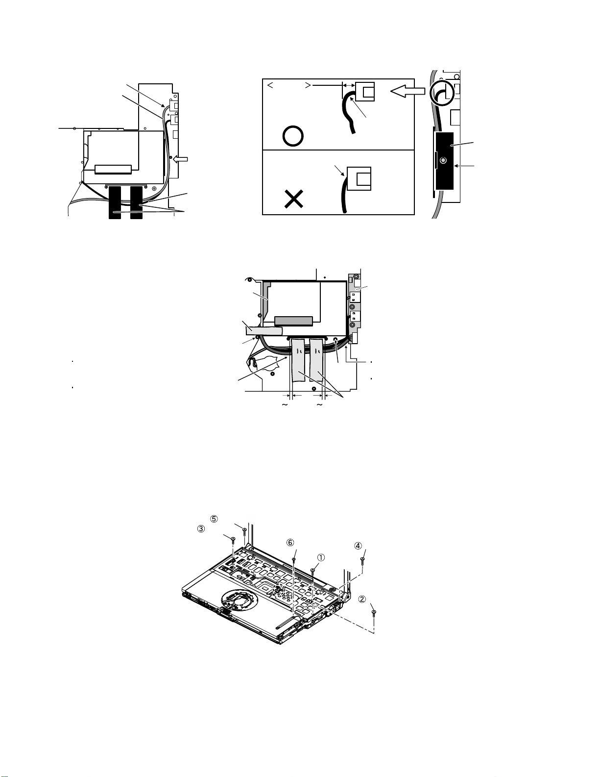
6.2.9. Removing the Antenna Board (L,R)
and the DC-IN Cable
Preparation : perform the section 6.2.1. , 6.2.2. , 6.2.4. and
6.2.8. first.
1. Remove the antenna cable(L) from the main terminal and
the antenna cable(R) from the AUX terminal and then
remove the antenna board(L, R) from the bottom case.
2. Remove the DC-IN cable(CN600) from the main board.
CN11
7. Turn it to arrow and remove the lithium battery connector
(CN3), LAN cable connector (CN16) and HDD FPC
connector (CN4) and then remove the main board.
Power Knob
LAN SW Knob
Tape
CN600
LAN
Cable
Antenna Board(L)
Antenna Cable(R)
Antenna Cable(L)
DC-IN
Cable
CN600
Antenna Board(R)
6.2.10. Removing the Wireless LAN
Module
Preparation : perform the section 6.2.1. , 6.2.2. , 6.2.4. and
6.2.8. first.
1. Peel off the tape on the wireless LAN module.
2. Open the wireless LAN module holding arms and remove
the wireless LAN module.
Tape
Lithium Battery
Cable
CN3
CN16
Wireless LAN Module
DC-IN Cable
Main Board
32
Page 35

6.2.11. Removing the MODEM
Preparation : perform the section 6.2.1. , 6.2.2. , 6.2.4. and
6.2.8. first.
1. Remove the 2 screws (O).
Screw (O):DXQT2+D25FNL(N8)
2. Remove the MODEM from main board connector (CN18)
as vertical.
Screw (O)Screw (O)
Modem
CN18
6.2.12. Removing the Card Bus Ejector
Preparation : perform the section 6.2.1. , 6.2.2. , 6.2.4. and
6.2.8. first.
1. Remove the 1 screw (P) from connection side of wireless
LAN.
Screw(P):DFHE5025XA(N1)
Screw(P)
Main Board
2. Turn to the card bus ejector side.
3. Remove the 2 hooks (C) from the connector (CN14).
Card Bus Ejector
CN14
Hook(C)
Main Board
33
Page 36

6.2.13. Removing the LCD Unit
Preparation : perform the section 6.2.1. , 6.2.2. and 6.2.4.
first.
1. Remove the 2 screws (M).
Screw(M):DXQT26+D5FNL(N14)
2. Remove the LCD cable from the connector (CN11) of the
main board.
3. Remove the inverter cable from the connector (CN10)
4. Remove the touch panel cable from connector (CN24).
Screw(M)
6.2.15. Removing the LCD Unit and the
LCD Rear
Preparation : perform the section 6.2.1. , 6.2.2. , 6.2.4. and
6. 2. 13. to 6.2.14 first.
1. Separate the LCD front and the LCD rear.
2. Remove the hinge (L).
Hook Position
LCD Unit
LCD Cable
CN10
CN11
Screw(M)
CN24
6.2.14. Removing the Hinge Cover
Preparation : perform the section 6.2.1. , 6.2.2. ,6.2.4 and
6.2.13. first.
1. Remove the 2 screws (Q) and then remove the hinge cover
(L,R).
Screw(Q):DRHM0076ZA(N3)
Screw(Q)
LCD Unit
HInge(L)
LCD Front
LCD Rear
Hinge(R)
6.2.16. Remove the Inverter
Preparation : perform the section 6.2.1. , 6.2.2. , 6.2.4. and
6.2.13 to 6. 2.15. first.
1. Remove the LCD cable from the inverter.
2. Peel off the conductive cloth(LCD cable) from the inverter.
3. Remove the inverter with inverter box.
LCD Front
LCD High voltage
2pin Wire Rod
LCD Hook
Hinge Cover(L)
2. Remove the 2 screws (R).
Screw (R):DRHM0076ZA(N3)
Screw(R)
Hinge Cover(R)
LCD Unit
Screw(Q)
Screw(R)
34
Inverter Box
Tape
Conductive Cloth
(LCD Cable)
LCD Cable
Page 37

6.3. Reassenbly instructions
6.3.1. Attention when CF-T4H series is repaired
· Please execute writing BIOS ID when you exchange the main board.
· Parts (sheet and rubber) etc. related various the conductive cloth and heat spreader cannot be recycled. Use new parts.
6.3.2. Assembly knowhow of part LCD
LCD rubber, LCD side rubber and LCD backing rubber’s putting
LCD Rubber (Upper
LCD Rubber(Upper)
LCD Side Rubber
LCD Back Rubber(Lower)
LCD Front Case
LCD cable processing
Clamping processing of LCD cable, LCD connector connection and putting of PET tape of cable
The LCD insulation sheet is peeled off.
The LCD cable is processed to the LCD frame clamping.
The LCD cable is connected with the connector.
The PET tape is put.
LCD Insulation Sheet
A red line of the cable is matched to the LCD frame externals.
Big Small
PET Tape
LCD Front Case
1 2mm
1
Be parallel after putting
2mm
LCD Frame Clamp
0
1mm
Connector
Putting of the conductive cloth
The conductive cloth
Process the part in the Signal line of the LCD cable in
Put
the conductive cloth
There must not be beginning to see from externals.
is put and after putting a both side tape is put.
on the connector surely.
Connector of externals match
LCD Insulation Sheet
the conductive cloth.
Connector
Both Side Tape
35
Insulation Sheet of edge match
0
1mm
Conductive Cloth
(LCD Label)
LCD Cable
Page 38

Putting of PET Tape
The cable must not run aground on the damper.
Along the LCD module and put the LCD cable (Inverter part) with the PET tape.
Putting of rear damper
Putting of PET Tape
TS Board
LCD Cable
(Inverter part)
Damper
PET Tape
Rear Damper
Conductive Cloth (LCD Cable)
LCD Cable
Insulation Sheet of edge match
Conductive Cloth (LCD Cable)
LCD Cable
Rib application putting of LCD front case
0
1mm
Extemals suiting of Frame outside
0
1mm
Processing of inverter cable
PET Tape
Inverter Cable
The cable must not run aground on the cushion.
LVDS Cable of edge match
LCD Cable
LVDS Cable of edge match
0 1mm
The cable must not come in succession.
36
Page 39

Putting of gasket (LCD)
Put on hinge (R) surely.
The line of the remainder
is put on hinge (R) side.
Putting of LCD damper(C)
Rib application putting of LCD front case
0
Putting of LCD Hook Cushion
Specificatione affixation of LCD Hook Cushion
Hinge (R)
LCD Damper(C)
1mm
Rib edge match of LCD front case
1mm
0
Gasket (LCD)
Externals suiting of reflector
0
1mm
Put the reflector part surely.
Plinth externals match
0
1mm
Rib application putting of LCD front case
0
1mm
pressure is applied to
double-sided tape portion
0 0.5mm
K502
K70
0 0.5mm
0 0.5mm
Drawing out specification of LCD cable
LCD Cable (Touch Panel)
LCD Cable (Inverter)
The cable is processed under the shaft .
Note:It is confirmed that the cable does not narrow
between cabinets.
0 0.5mm
Putting of conductive cloth of LCD cable
70
3mm
Conductive cloth is wrapped
(Leave the half)
Hook is attached
to the left
37
Page 40

LCD cable processing
LCD Cable
8mm
6
Conductive Cloth
6.3.3. Installation and Line processing of Speaker
Putting of speaker fixation ring
About 8mm at the edge of conductive cloth is
putting on the rib of the bottom case for conduct
The cable is processed under the convex part
The cable is processed to the ditch
Speaker Fixation Ring
Processing of speaker cable
Putting of speaker box
Put according to 4 ribs.
Solder
Red line
Speaker Cable
The cable is not loosening between the rib and the pin.
Match case
Black line
Touch the boss
sign to the center in the terminal of the speaker.
2.5mm From the rib to the terminal
2
The double coating part of
the cable according to the ditch of the case
PET Tape
Putting of speaker box
0 2mm
38
Touch the Case’s wall
Page 41

6.3.4. Assembly of Touch Pad
Putting of PAD cover tape
2mm
1mm
PAD cover
Putting of PAD sheet
This line must
become vertical
PAD sheet
After putting of the
PAD sheet, the
Flaking off paper is
peeled off
Sets in the dent
PAD cover tape
0.5mm
1mm
Insertion of PAD FFC
PAD FFC
Putting of Touch Pad
PAD FFC is
inserted in the
connector.
(Direction where
the reinforcement
version is seen)
Touch Pad
Pin for positioning
The touch pad
is put
Touch Pad
6.3.5. Processing of DC-IN Cable and Coaxial Cable
Installation of Pad button
Puted in the gasket
ditch
Inserted in the
positioning pin
Pad button
Latch is inserted in the top case(4 places)
Putting of pad cover
The hooks are hooked
It is confirmed that all
LED lenses fit in the
hole of the pad cover
Pad Cover
The hooks are inserted
Coaxial cable
The cable is processed with
the boss between ribs
6.3.6. Obtaining of Side Cover (L)
The upper part is shut with
lower hooks put on the
bottom case.
Side Cover(L)
DC Jack Holder
the under hooks is hooked
the bottom case
The cable is processed to
the ditch of the bottom case
Confirm the terminal is vertical
the under hooks is hooked
the bottom case
39
Page 42
6.3.7. Processing of MODEM Cable and LAN Cable
Insert LAN cable
previously
LAN Cable
The cable is
processed with the
boss between ribs
MODEM Cable
PET Tape
Standard
The cable
must enter
in the set of
3-5mm
The state that the tension hangs is NG
6.3.8. Processing of USB Cable
Give slack
to the drawing
out part
USB Sheet
The USB sheet
is put and the
cable is held
HDD Unit
PET Tape
Do not run aground in the boss
Process the line to 3 cables in parallel based on
the difference of the concave part of the bottom
case
Order is USB, modem, and LAN cable from this
side
2mm 0 2mm
0
Boss
USB Board
The Cable must not enter under the
HDD unit
Do not run aground in the boss
PET Tape
6.3.9. Screw tightening procedure of Each Unit
When serving, the screw tightening is executed according to the undermentioned procedure.
1. Screw tightening of top case
1-1. DXQT2+E6FNL(K:N12) is tightened. No.1 to No.3
1-2. DXQT26+D8FCL(L:N15) is tightened. No.4 ,No.5
1-3. DXHM0056ZA(J:N6) is tightened. No.6
Screw(L)
Screw(K)
Screw(J)
Screw(K)
Screw(J)
40
Screw(K)
Page 43

2. Attachment preparation of Key Board
2-1. Putting of Heat Sheet KB Large
Inclination is set
to 0.5mm or less.
Inclination is set
to 0.5mm or less.
Touch the KB hole
Touch the KB hole
2-2. Putting of tape
0 0.5mm
0.5 1.5mm
0 1mm
Tape(KBD)
8 1mm
0 1mm
(KBD)
0.5 1.5mm
KeyBoard exterior and FPC are parallel.
3. Screw tightening of bottom case (1)
The keyboard is inserted, and after the keyboard hooks are inserted in order of a and b while holding the keyboard, the screw
tightening is done in the following order.
Note:The sheet metal must not run aground on the rib (Refer to the figure below).
2-1. DXHM0039ZA(D:N5) is tightened. No.1 to No.7
2-2. DXHM0057ZA(G:N7) is tightened. No.8 to No.12
Screw(D)
Screw(D)
Screw(G)
Screw(G)
Screw(G)
Screw(G)
Screw(D)
Screw(D)
Screw(D)
41
Screw(D)
Keyboard Hook b
Screw(D)
Keyboard Hook a
Screw(G)
Keyboard
Hook
OK
Top Case Rib
NG
Assembly reference chart
Top Case
Page 44

4. Screw tightening of bottom case (2)
The keyboard is inserted, and after tightening of the screw, the keyboard hooks are inserted in order of the following.
3-1. DXQT2+E12FNL(B:N11) is tightened. No.1 to No.4
3-2. DXQT2+D4FNL(F:N9) is tightened. No.5
3-3. DXQT2+E10FNL(E:N10) is tightened. No.6
3-4. DFHE5035ZA( H:N2) is tightened. No.7
3-5. DFHE5025XA(C:N501) is tightened. No.8
3-5. KIYE50000022(I:N500) is tightened. No.9
Screw(C)
Screw(B)
Screw(E)
Screw(F)
Screw(B)
Screw(B)
Screw(B)
Screw(H)
Screw(I)
6.3.10. Affixation of Win Logo Label (XP), CENTRINO Label and Energy Star Label
Win Logo Label(XP)
In the inclination at the time of putting the win logo label,
the CENTRINO label and energy star label the both ends
difference is within 0.2mm
<Attention>
Confirm whether the paste of the label has overflowed
after the win logo label and putting of the CENTRINO label
and energy star label.
2 5mm
CENTRINO Label
2
5mm
Energy Star Label
Top Case
42
2
5mm5 7mm
Page 45

A
A
V
K
g
g
VGA
7 Explanation of Harddware
7 1 System Block Diagram
DothanULV
TTTT
TTTT
BBBB
BBBB
4444
4444
llll
oooo
cccc
kkkk
DDDD
iiii
aaaa
gggg
rrrr
aaaa
llll
oooo
cccc
kkkk
DDDD
iiii
mmmm
aaaa
gggg
rrrr
aaaa
mmmm
DothanULV
DothanULVDothanULV
1.2GHz(/600MHz)
Core 0.940V(/0.812V)
FSB 1.05V
L2 Cache=2MB
CK410M
Micro-DIMM socket
172pin (Max.1GB)
Main Memory
(DDR2-SDRAM CSP)
512MB (32Mx16 x 8pcs)
HDD
2.5”
BIOS FLASH
1MB
SST49LF008
SST49LF008
SST49LF008SST49LF008
TPM
PAT
M-BUS
400MHz
North Bridge
Alviso
Alviso----GMS
GMS
AlvisoAlviso
GMSGMS
1.25V
South Bridge
ICH6
ICH6----MMMM
ICH6ICH6
1.5V
FSB 400MHz
DMI
USB1.1
USB2.0
USB2.0
Port Replicator
Connector (Config)
(for CRT)
LCD
12.1”
XGA
Touch Screen
Controller
)
(Confi
GA Port
USB2.0
x2
Port
Replicator
(Config)
USB2.0x4
HUB
Tou ch
Screen
(Confi
RJ45
)
Main
Battery
Li-Ion
Mic-JACK
HP-JACK
Speaker
(Mono)
Tou ch
PAD
EC, KBC
M306KA
M306KA
M306KAM306KA
Internal
KB
AC97
Codec
STAC9751
STAC9751
STAC9751STAC9751
LPC-BUS
3.3V
AC-LIN
3.3V
PCI-BUS
3.3V
43
Ethernet
Controller
RTL8101L
RTL8101L
RTL8101LRTL8101L
CB+SD
Controller
R5C811
R5C811
R5C811R5C811
MiniPCI
Type3
MDC
1.5
MDC
Modem
Module
DC-IN
RJ45
(LAN)
SD Card
PCMCI
Type-II
WLAN
Module
RJ11
(Modem)
Page 46

y
䌁䌃 A䌤䌡䌰ter
(DCIN JACK)
AC OVP
&UVP
䌌䌩䌮䌥 䌓䌗
to(*㪈)
AC㪈5
DCIN&BATT
䌆䌕䌓䌅
(2A)
䌂䌡䌣䌫 䌌䌩䌧䌨䌴
INVERTER 䌕䌎䌉䌔
VA5
Battery
+(㪈)
VBATT(3)
䌖䌁䋳(4)
VSEL㪈(5)
VSEL2(6)
SMBDATAE(7)
SMBCLKE(8)
BATDTCT#(9)
-(㪈0)
䌓䌡fety Block
VA5,VA3,VA㪈5
VB㪈8,VCPUCORE
VCCP,VC25
CHGON
EC
(M306K7)
䋨䋪䋱䋩
Safty Circuit
(OVP Detect)
䌌䌡䌴䌣䌨
to(*㪈)
䌌䌩䌮䌥 䌓䌗
Battery Charger
(LTC4008EGN)
CHGPWM
from batter
䌌䌩䌮䌥 䌓䌗
AC㪈5
VSENSE
ISENSE
BATDTCT#
to Line SW
䌌䌯䌡䌤 䌓䌗
䋳䋮䋳䌖䋯䋵䋮䋰䌖 DC/DC
CONVERTER Block
䋨䋨LTC3728LXCUH䋩
䌌䌯䌡䌤 䌓䌗
䌌䌯䌡䌤 䌓䌗
SLP_S3#
CPU CORE DC/DC
CONVERTER Block
䋨LTC3734EUH䋩
VCCP䇭VC25 DC/DC
CONVERTER Block
䋨LTC3728LXCUH䋩
VC5
SLP_S3#
VA3
VB3
SLP_S4#
VC3
䌖䌃PUCORE
VRON#
VRON#
VCCP(㪈.05V)
䌖䌃25
44
VA㪈5䇭 DC/DC
CONVERTER Block
䋨LTC3728LXCUH䋩
VB㪈8 DC/DC
CONVERTER Block
䋨LTC3728LXCUH䋩
VB㪈8
VC09 DC/DC
CONVERTER Block
䋨BD3533F-E2䋩
䌓䌌P_S3#
䌌䌯䌡䌤 䌓䌗
䌓䌌P_S4#
VA㪈5
VC㪈5
䌓䌌P_S3#
VB㪈8
䌖䌃09
Page 47

8. Extended View
8.1.Display Section
K7
E3
K37
K14
K17
K28
K30
K15
K30
K502
E501
N14
N3
K50
K60
K501
K4
K30
K29
K30
N14
E500
K50
K76
K18
K5
K68
K61
N3
K53
E17
K29
K22
K25
N3
K10
K500
K22
K65
K70
K27
K28
K25
Screw tightening torque
N3
Page 48

LCD Unit Ass'y / Pen Holder Section
K507
K506
K505
K503
K504
E501
E501-1-1
E501-1-2
E501-1-1
E501-1-4
E501-1-6
E501-1
E501-1-4
E501-1-3
E501-1-2
E501-1-5
E501-2
Page 49

8.2. Cabinet Section
K509
K1
K41
K41
K41
K8
E19
K42
E2
K54
N12
K39
N15
K16
K73
K51
K47
K40
K40
E18
K517
K72
N12
K88
K81
K508
K89
K72
N12
K31
K6
K69
K90
K13
K36
K64
a
N15
b
E12
K48
E15
K49
E7
Screw tightening torque
N6
Page 50

8.3. Bottom Section
K78
N1
N500
E14
CN14
N4
K530
E21
K59
CN13
SW6
SW7
K84
K79
CN22
h
N8
K75
E11
N2
K511
CN12
JK1
f
N8
JK2
K24
K82
K516
c
K71
K83
N13
g
c
CN601
CN24
e
K19
K80
d
K35
K26
E6
K77
E9
K85
a
E22
h
b
K515
K510
Screw tightening torque
K524
Tape
N15
A3
K55
K12
K514
K12
d
E5
CN1053
K55
K523
K524
CN1052
E13
K52
E4
i
N15
K513
N7
K2
N9
K3
N16
N5
K86
K62
N10
N7
N11
N5
K66-1
K66-1
N7
N11
K519
K66-1
K518
N7
N5
K520
N5
N5
K522
N5
N5
N11
N501
E10
K66
N11
e
E8
f
g
K512
E1
i
E20
K33
N501
K521
Page 51

9 Replacement Parts List
Note: Important Safety Notice
Components identified by mark have special characteristics important for safety.
When replacing any of these components, use only manufacturer's specified parts.
CF-T4HWETZBM
REF.NO. and AREA PART NO. DESCRIPTION Q'TY
Main Block Unit
CN12 K1FB315BA003 VGA CONNECTOR 1
CN13 K1NA09E00076 CONNECTOR 1
CN14 K1NA68E00096 CONNECTOR 1
CN22 K1FY150BA007 IO CONNECTOR 1
CN24 K1KA04BA0014 CONNECTOR 1
CN601 K1KA10B00233 CONNECTOR 1
CN1052 K1FB104B0055 USB CONNECTOR 1
CN1053 K1FB104B0055 USB CONNECTOR 1
JK1 K2HC103B0205 HEADPHONE JACK 1
JK2 K2HC103B0205 MICROPHONE JACK 1
SW6 ESD165225 POWER SW 1
SW7 K0D112B00071 W-LAN SW 1
SW951 K0D113B00081 SLIDE SW 1
E1 CR2032/S5Y LITHIUM BATTERY 1
E2 DFJK12U112BB PAD FFC 1
E3 DFJS963ZA TP CABLE 1
E4 DFJS958ZB LAN CABLE 1
E5 DFJS980ZA MAIN-SUB CABLE 1
E6 DFJS961ZB DC-IN CABLE 1
E7 DFJS962ZA SP CABLE 1
E8 DFJS973ZA MODEM CABLE 1
E9 DL3UP1436ABA PCB, MAIN RTL 1
E10 DL3UP1443AAA FPC UNIT, HDD 1
E11 N1ZYYY000002 ANTENNA PCB-L ASS'Y 1
E12 N1ZYYY000003 ANTENNA PCB-R ASS'Y 1
E13 DL3UP1477AAA PCB, 2-PORT USB RTL 1
E14 K1YYZZ000060 CONNECTOR 1
E15 L0AA01A00018 SPEAKER 1
E17 N0GB1J000012 INVERTER 1
E18 N2AZZJ000038 KEY BOARD US 1
E19 N2EAYYY00006 TOUCH PAD 1
E20 N3CAYYY00006 HDD 1
E21 N5HAZ0000012 MODEM 1
E22 N5HZC0000014 WIRELESS LAN MODULE 1
E500 DL3UP1498LAA PCB, TS RTL 1
E501 DFWV08A0083 LCD UNIT ASS'Y 1
E501-1 DFWV84A0266 TOUCH SCREEN PANEL KIT 1
E501-1-1 DFHG1824ZA FRONT TP CUSHION A 2
E501-1-2 DFHG1825YA FRONT TP CUSHION B 2
E501-1-3 DFHG1826ZA FRONT TP CUSHION C 1
E501-1-4 DFHG1837ZA FRONT TP CUSHION D 2
E501-1-5 DFHG1849ZB FRONT TP CUSHION E 1
E501-1-6 DFHR9063ZA PROTECTIVE FILM 1
E501-2 DFHR3630ZA TS FPC SPACER 1
Accessories
A1 CF-AA1623AM6 AC ADAPTOR 1
A2 K2CG3DR00003 AC CABLE 1
A3 CGR-B/979A LITHIUM ION BATTERY PACK 1
A4 DFQX5573ZA MANUAL 1
A500 DFJS954ZA MODEM CABLE 1
A501 DFHR9081XA PEN 1
Page 52

A502 DFME0148ZA TETHER T4 1
A503 DFHS9017ZA CLOTH ASS'Y 1
Packing Material
P1 DFPE0806ZB HOLDER 1
P2 DFPE0812ZB PAD W 1
P4 DFPK1037YA ACCESSORIES BOX 1
P5 DFPK1194YA PACKING CASE 1
P6 DFPN0832ZA CUSHION T 2
P7 DFPN0833ZA CUSHION B 2
Mechanical Parts
K1 DFBC0315ZE-0 PAD BUTTON 1
K2 DFBD0180ZB-0 POWER KNOB 1
K3 DFBD0182ZA-0 LAN SW KNOB 1
K4 DFBH3041ZA HINGE-L TP 1
K5 DFBH3042ZA HINGE-R TP 1
K6 DFBS0068ZC-0 LCD KNOB 1
K7 DFGB0089VB-0 PANASONIC LABEL 1
K8 DFGE0108ZC-0 PAD COVER 1
K10 DFHG1811ZA LCD BATT RUBBER TP 1
K12 DFGX0428ZA-0 BATT SHEET(T4) 2
K13 DFHE0215ZA SHEET 1
K14 DFHE0436ZA CLOTH LCD CABLE 1 1
K15 DFHE0843ZA LCD MAGNET 1
K16 DFHE0844ZA GASKET PAD 1
K17 DFHE0943ZA GASKET CLOTH (LCD CABLE) 1
K18 DFHE0945ZA GASKET CLOTH (LCD) 1
K19 DFHE0953ZA SHEET 1
K22 DFHG1546ZB-0 LCD RUBBER 2
K24 DFHG1744ZA M-PCI CUSHION 1
K25 DFHG1766ZA-0 LCD SIDE RUBBER 2
K26 DFHG1767ZA-0 DC JACK HOLDER 1
K27 DFHG1771ZA LCD DAMPER A 1
K28 DFHG1821ZA LCD DAMPER B TP 2
K29 DFHG1773ZA LCD DAMPER C 2
K30 DFHG1822ZA LCD SIDE DAMPER TP 4
K31 DFHG1778ZA PCMCIA STOPPER CUSHION 1
K33 DFHG1809YA HDD CASE ASS'Y T4 USA 1
K35 DFHG1786ZA CPU CUSHION 1
K36 DFHG1787ZA MINI-PCI CUSHION 1
K37 DFHG1797ZA REAR DAMPER 1
K39 DFHP7098ZA KB TAPE 1
K40 DFHP7106YA BOTH SIDES TAPE 2
K41 DFHP7140ZA TAPE, CPU 3
K42 DFHP7221YA PAD SHEET 1
K47 DFHR3416ZA SPACER CU 1
K48 DFHR3A37ZA SPEAKER RING 1
K49 DFHR3A39ZA SPEAKER BOX 1
K50 DFHR3A78ZA LCD INSULATOR 2
K51 DFHR3A88ZA KB PLATE SHEET 1
K52 DFHR3C25ZA USB SHEET US 1
K53 DFHR3A95ZA INVERTER TAPE 1
K54 DFHR3B19ZA HINGE BACKUP SHEET T4 1
K55 DFHR3B22ZA BOTTOM BACKUP SHEET 2
K59 DFKE0772ZA-0 ANTENNA COVER-L 1
K60 DFKE0776ZA-0 HINGE COVER-L TP 1
K61 DFKE0777ZA-0 HINGE COVER-R TP 1
K62 DFKE0778ZA-0 DIMM COVER (LIGHT) 1
K64 DFKE0783ZA-0 SIDE COVER-R 1
Page 53

K65 DFKF0257ZA-0 LCD FRONT TP 1
K66 DFKF8166ZA-0 BOTTOM CASE USA ASS'Y 1
K66-1 DFHG371ZA-1 FOOT RUBBER 3
K68 DFKM0482ZA-0 LCD REAR (SANKI) 1
K69 DFKM8172XA-0 TOP CASE ASS'Y 1
K70 DFMD1196ZA LCD HOOK TP 1
K71 DFMD3121ZA MDC PLATE 1
K72 DFMD4057ZA KB HOOK F999 2
K73 DFMD7A52ZA KB PLATE 1
K75 DFMX0635ZB TAPE 1
K76 DFMX1155ZA INVERTER BOX 1
K77 DFMX1156ZA MAIN PW SHEET1 1
K78 DFMX1160ZA PCMCIA-MAIN SHEET 1
K79 DFMX1184ZA SW CABLE SHEET 1
K80 DFMY0399ZA MCH RUBBER 1
K81 DFMY3191YA HEAT SPREADER TOP 1
K82 DFMY3192ZA HEAT SPREADER BOTTOM 1
K83 DFMY3206ZA MEMORY SHEET TOP 1
K84 DFMY3207ZA MEMORY SHEET BOTTOM 1
K85 DFMY3208ZA W-LAN SHEET 1
K86 DFQT6299YA DIMM COVER SHEET 1
K88 DFQT9974ZA WINDOWS XP LABEL (FOR NOTE) 1
K89 DFQT9948ZA CENTRINO LABEL 1
K90 DFUD0040ZA LATCH SPRING 1
K500 DFHR3C02ZA BATT RUBBER TAPE 1
K501 DFHR3C01ZA TAPE TP 1
K502 DFHG1836ZA LCD HOOK CUSHION TP 1
K503 DFHG1810ZA-0 PEN HOLDER 1
K504 DFHP7223ZA PEN HOLDER TAPE 1
K505 DFHG1848ZA PEN FIX CUSHION 1
K506 DFHR3C48ZA PEN FIX SHEET 1
K507 DFHR3C44ZA HOLDER BOTTOM SHEET 1
K508 DFQT9675ZA ENERGY STAR LABEL 1
K509 DFHP7220ZB PAD COVER TAPE 1
K510 DFHR3B98ZA HDD FPC SHEET 1
K511 DFHR3C33YA LCD CABLE FIX SHEET 1
K512 DFKE0781ZA-0 RJ DUST COVER 1
K513 DFHP7228ZA RJ DUST COVER FIX TAPE 1
K514 DFHR3C13ZA RJ CABLE SHEET 1
K515 DFHR3C34ZA TP CABLE FIX SHEET 1
K516 DFHG1847ZA TP CABLE FIX CUSHION 1
K517 DFMY0421ZA HEAT SHEET KB LARGE 1
K518 DFGT1032ZA BOTTOM SHEET USA 1
K519 DFGT1075ZA BOTTOM SHEET USA 2 1
K520 DFGX0430ZA-0 BOTTOM HEAT SHEET 1
K521 DFGX0444ZA-0 HDD COVER HEAT SHEET 1
K522 DFKE0782ZA-0 HDD COVER 1
K523 DFKH1016ZA-0 HANDY STRAP 1
K524 DFMD1191YA HANDY STRAP ANGLE 2
K530 DFHE0603ZA LCD CONNECTOR SHEET 1
N1 DFHE5025XA SCREW 1
N2 DFHE5035ZB SCREW 2
N3 DRHM0076ZA SCREW 4
N4 DRQT2+G6FKL SCREW 1
N5 DXHM0039ZA SCREW 7
N6 DXHM0056ZA SCREW 1
N7 DXHM0057ZA SCREW 5
N8 DXQT2+D25FNL SCREW 3
N9 DXQT2+D4FNL SCREW 1
N10 DXQT2+E10FNL SCREW 1
Page 54

N11 DXQT2+E12FNL SCREW 4
N12 DXQT2+E6FNL SCREW 3
N13 DXQT2+E6FNL SCREW 2
N14 DXQT26+D5FNL SCREW 2
N15 DXQT26+D8FCL SCREW 6
N16 XSB2+4FNL SCREW 1
N500 K1YE50000022 SCREW, I/O PIN 2
N501 DFHE5025XA SCREW 2
 Loading...