

panasonic CF-48 Service Manual
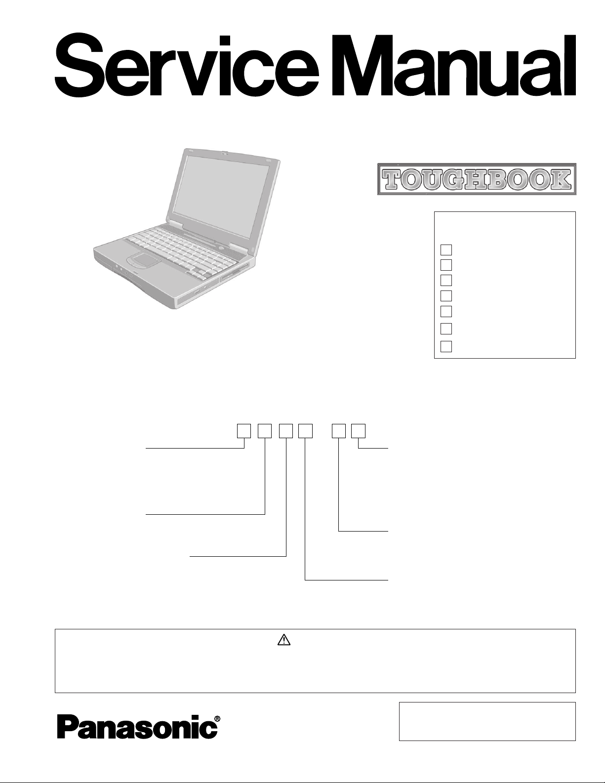
ORDER NO. CPD0010002C0
Model No.CF-48 A
LCD type
3: for 13.3" TFT Color
4: for 14.1" TFT Color
HDD type / RAM size
A: 10 GB / 64 MB
F: 20 GB / 128 MB
Area
M: for U.S.A. and Canada
E: for U.K.
G: for Germany
F: for France
S: for Sweden
T: for Italy
Drive
A: FloppyDisk drive / CD-ROM drive
B: FloppyDisk drive / DVD-ROM drive
CPU type
M: for Intel Mobile Pentium III
Processor 600 MHz
N: for Intel Mobile Pentium III
Processor 700 MHz
Operating System
C: Microsoft Windows NT
D: Microsoft Windows 2000
E: Microsoft Windows 98
Notebook Computer
CF-48
This is the Service Manual for
the following areas.
M ...for U.S.A. and Canada
E ...for U.K.
G ...for Germany
F ...for France
S ...for Sweden
Model Number Reference
The models in the CF-48 series are numbered in accordance with the types of the CPU, LCD
and HDD etc. featured by the product.
This service information is designed for experienced repair technicians only and is not designed for use by the general public. It does not contain
warnings or cautions to advise non-technical individuals of potential dangers in attempting to service a product. Products powered by electricity
should be serviced or repaired only by experienced professional technicians. Any attempt to service or repair the product or products dealt with in
this service information by anyone else could result in serious injury or death.
WARNING
- 1 -
© 2000 Matsushita Electric Industrial Co., Ltd.
All rights reserved. Unauthorized copying and
distribution is a violation of law.
T ...for Italy
P ...for Spain
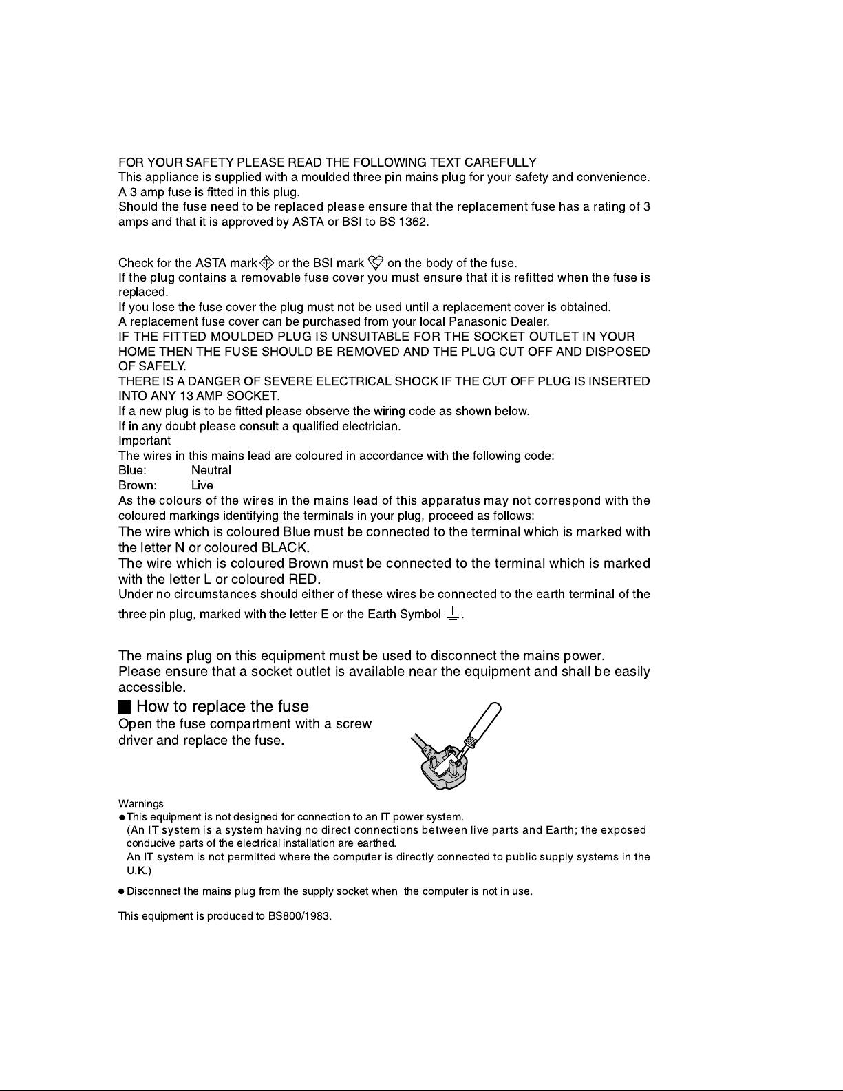
For U.K.
WARNINGS
FOR YOUR SAFETY PLEASE READ THE FOLLOWING TEXT CAREFULLY
This appliance is supplied with a moulded three pin mains plug for your safety and convenience.
A 3 amp fuse is fitted in this plug.
Should the fuse need to be replaced please ensure that the replacement fuse has a rating of 3
amps and that it is approved by ASTA or BSI to BS 1362.
Check for the ASTA mark or the BSI mark on the body of the fuse.
If the plug contains a removable fuse cover you must ensure that it is refitted when the fuse is
replaced.
If you lose the fuse cover the plug must not be used until a replacement cover is obtained.
A replacement fuse cover can be purchased from your local Panasonic Dealer.
IF THE FITTED MOULDED PLUG IS UNSUITABLE FOR THE SOCKET OUTLET IN YOUR
HOME THEN THE FUSE SHOULD BE REMOVED AND THE PLUG CUT OFF AND DISPOSED
OF SAFELY.
THERE IS A DANGER OF SEVERE ELECTRICAL SHOCK IF THE CUT OFF PLUG IS INSERTED
INTO ANY 13 AMP SOCKET.
If a new plug is to be fitted please observe the wiring code as shown below.
If in any doubt please consult a qualified electrician.
Important
The wires in this mains lead are coloured in accordance with the following code:
Blue: Neutral
Brown: Live
As the colours of the wires in the mains lead of this apparatus may not correspond with the
coloured markings identifying the terminals in your plug, proceed as follows:
A S A
The wire which is coloured Blue must be connected to the terminal which is marked with
the letter N or coloured BLACK.
The wire which is coloured Brown must be connected to the terminal which is marked
with the letter L or coloured RED.
Under no circumstances should either of these wires be connected to the earth terminal of the
three pin plug, marked with the letter E or the Earth Symbol .
The mains plug on this equipment must be used to disconnect the mains power.
Please ensure that a socket outlet is available near the equipment and shall be easily
accessible.
How to replace the fuse
Open the fuse compartment with a screw
driver and replace the fuse.
Warnings
This equipment is not designed for connection to an IT power system.
(An IT system is a system having no direct connections between live parts and Earth; the exposed
conducive parts of the electrical installation are earthed.
An IT system is not permitted where the computer is directly connected to public supply systems in the
U.K.)
Disconnect the mains plug from the supply socket when the computer is not in use.
This equipment is produced to BS800/1983.
- 2 -
LASER SAFETY INFORMATION
Vorsicht!
Explosionsgefahr bei unsachgemäßem Austausch der Batterie. Ersatz nur durch denselben order einen vom
Hersteller empfohlenen ähnlichen Typ. Entsorgung gebrauchter Batterien nach Angaben des Herstellers.
For U.S.A.
Class 1 LASER-Product
This product is certified to comply with DHHS Rules 21 CFR Subchapter J.
This product complies with European Standard EN60825 (or IEC Publication 825)
For all areas
This equipment is classified as a class 1 level LASER product and there is no hazardous LASER radiation.
Caution:
(1) Use of controls or adjustments or performance of procedures other than those specified herein may result in
hazardous radiation exposure.
(2) The drive is designed to be incorporated into a computer-based system or unit which has an enclosing cover.
It should never be used as a stand alone drive.
Danger:
The serviceman should not remove the cover of drive unit and should not service because the drive unit is a nonserviceable part.
Please check DANGER label on PD-drive unit.
• Unplug the AC power cord to the equipment before opening the top cover of the drive.
• When the power switch it on, do not place your eyes close to the front panel door to look into the interior of the unit.
LASER Specification
Class 1 level LASER Product
Wave Length: DVD 658±8 nm
CD 775~815 nm
Laser safety information is appropriate only when drive with laser is installed.
LITHIUM BATTERY
• CAUTION
Danger of explosion if battery is incorrectly replaced.
Replace only with the same or equivalent type recommended by the equipment manufacture.
Discard used batteries according to the manufacturer's instructions.
LITHIUMBATTERIES
PILE AU LITHIUM
ATTENTION: IL Y A DANGER D'EXPLOSION S' IL Y A REMPLACEMENT INCORRECT DE LA PILE.
REMPLACER UNIQUEMENT AVEC UNE PILE DU MÈME TYPE OU D'UN TYPE RECOMMANDÉ PAR LE
CONSTRUCTEUR. METTRE AU RÉBUT LES PILES USAGÉES CONFORMÉMENT AUX INSTRUCTIONS DU
FABRICANT.
- 3 -

CONTENTS
1. Specificayions .......................................................................................................... 1-1~1-2
2. Names and Functions of Parts ............................................................................... 2-1, 2-2
3. Technical Information .............................................................................................. 3-1~3-4
3.1 System Overview ..................................................................................................................3-1, 3-2
3.2 System Memory Map ............................................................................................................ 3-3
3.3 I/O Address Map ................................................................................................................... 3-4
4. Diagnosis Procedure ............................................................................................... 4-1~4-12
4.1 Basic Procedures .................................................................................................................. 4-1
4.2 Power On Self Test ................................................................................................................4-2
4.3 List of Error Codes ................................................................................................................ 4-3, 4-4
4.4 Diagnosis Map ...................................................................................................................... 4-5~4-12
5. Diagnosis Test .......................................................................................................... 5-1~5-16
5.1 Diagnostic Test Procedure .................................................................................................... 5-1~5-10
5.2 Error Message ...................................................................................................................... 5-11~5-16
6. Disassembly/Reassembly ....................................................................................... 6-1~
6.1 Removing the Battery Park ................................................................................................... 6-1
6.2 Removing the HDD Unit ........................................................................................................ 6-1
6.3 Removing the RAM Cord and the RTC Battery.....................................................................6-2
6.4 Removing the MINI-PCI Modem Card................................................................................... 6-2
6.5 Removing the CD-ROM Drive ............................................................................................... 6-2
6.6 Removing the Center Cover.................................................................................................. 6-3
6.7 Removing the Keyboard ........................................................................................................ 6-3
6.8 Removing the Top Shild Plate ............................................................................................... 6-4
6.9 Removing the LCD Unit ........................................................................................................ 6-4
6.10 Removing the SuperDisk Drive or the FloppyDisk Drive .......................................................6-4
6.11 Removing the Top Cabinet and Sub PCB Angle ................................................................... 6-5
6.12 Removing the IF PCB ........................................................................................................... 6-5
6.13 Removing the LED PCB, MAIN PCB, VGA/CPU Heat Sink, Fan,
I/O Plate and COM PCB ....................................................................................................... 6-6
6.14 Removing the LCD ................................................................................................................ 6-7
6.15 Removing the PAD PCB ........................................................................................................ 6-8
6.16 Removing the Speaker.......................................................................................................... 6-8
6.17 Removing the IC Card Cover and the Port Replicator Cover ................................................ 6-9
6.18 Removing the HDD ............................................................................................................... 6-9
6.19 Removing the FDD................................................................................................................ 6-9
6.20 Removing the CD-ROM Drive or the DVD-ROM Drive .......................................................... 6-9
7. Wiring Connection Diagram ................................................................................... 7-1
8. Exploded Views ........................................................................................................ 8-1~8-4
9. Replacement Parts List ........................................................................................... 9-1~9-12
- 4 -
1. Specifications
This page provides the specifications for the model CF-48xxxxAxx. The model number will change depending
on the configuration of the unit, such as, CPU speed, memory size, HDD size, Operating System, LCD type, and
whether a CD-ROM drive, a SuperDisk drive, a DVD-ROM drive, or a LAN card is included or not.
To check the model number:
Check the bottom of the computer or the box the computer came in at the time of purchase.
To check CPU speed:
Use DMI Viewer in [Start] - [Programs] - [Panasonic] - [DMI Viewer].
To check memory and the Hard Disk Drive (HDD) size:
Access the HDD’s “Properties” to check its capacity.
1. Run the Setup Utility.
2. The memory size is confirmed in [System Memory] of the [Main] menu. The hard disk drive size is confirmed in
[Primary Master] of the [Main] menu.
Main Specifications
Model No.
CPU
Memory
(Expandable to)
Video Memory
LCD Type
Displayed Colors*
Hard Disk Drive
Operating System
*1A 16 M color display is achieved by using the dithering function.
2
*
1GB = 109 bytes
CF-48xxxxAxx
Mobile Pentium® III Processor
®
600 MHz featuring Intel
700 MHz featuring Intel
SpeedStepTM Technology (CF-48Mxxxxxx)
®
SpeedStepTM Technology (CF-48Nxxxxxx)
L1 Cache Memory: 32 KB
L2 (Second) Cache Memory: 256 KB
MB (320 MB Max.) (for CF-48xxAxxxx)
64
128MB (384 MB Max.) (for CF-48xxFxxxx)
8 MB
13.3 type (TFT) (for CF-48x3xxxxx)
14.1" type (TFT) (for CF-48x4xxxxx)
1
256/65536/16M colors
(640 x 480 dots/800 x 600 dots/1024x768 dots)
10 GB*2 (for CF-48xxAxxxx)
2
20 GB*
Microsoft
Microsoft
Microsoft
(for CF-48xxFxxxx)
®
Windows® 98 Second Edition (for CF-48xxxxxEx)
®
Windows® 2000 (CF-48xxxxxDx)
®
Windows NT® (CF-48xxxxxCx)
1 - 1
Other Specifications
Keyboard
Floppy Disk Drive
CD-ROM Drive
DVD-ROM Drive
Slots
Interface
Pointing Device
Speaker
Utility Programs
Sound
Battery Pack
Battery
Clock Battery
AC adaptor*
5
Power Consumption*
Environment
Physical Dimensions
Weight
6
(W X H X D)
87 keys for European market
88 keys for US market
720 KB/1.44 MB
for CF-48xxxAxxx
for CF-48xxxBxxx
(two-mode)
PC Card Slots Two Type I or Type II, or one Type III
Allowable current 3.3 V: 400 mA, 5 V: 400 mA
(total for two slots)
RAM Module Slot*1144-pin, 3.3-V, SO-DIMM, SDRAM, PC100 Compliant
Parallel Port Dsub 25-pin female
External Display Port Mini Dsub 15-pin female
Serial Port Dsub 9-pin male
Microphone Jack*
2
Miniature jack, 3.5 DIA
Headphone Jack Miniature jack, 3.5 DIA
Impedance 32 W, Output Power 4 mW x 2
External Keyboard/Mouse Port Mini DIN 6-pin female
Expansion Bus Connector Dedicated 100-pin female
USB Port 4-pin x 2
Internal Modem Data: 56 kbps (V.90 & K56flex) FAX:14.4 kbps
Touch Pad
Stereo Speaker
(built in)
Setup Utility, DMI Viewer
HRTF 3D positional audio support 16-bit stereo, WAVE and MIDI playback
Li-ion 11.1 V, 5.4 Ah
Operating Time*
Charging Time*
3
Approx. 2.0 hours - 5.0 hours
3
Power On Approx. 5.5 hours
Power Off Approx. 3.0 hours
Coin type lithium battery 3.0 V
Input 100 V - 240 V AC, 50 Hz/60 Hz Output 15.6 V DC, 3.85 A
Approx. 45 W*7 / Approx. 70 W
(maximum when recharging in the ON state)
In use Temperature 5 ˚C to 35 ˚C*8 {41 ˚F to 95 ˚F}
Humidity 30% to 80% RH (No condensation)
Not in use Temperature -20 ˚C to 60 ˚C {-4 ˚F to 140 ˚F}
Humidity 30% to 90% RH (No condensation)
307 mm X 45 mm X 260 mm
Approx. 3.4 kg
{Approx. 7.4 lb.}
{12.1 " X1.8 " X 10.2 "}
<Model with both an internal modem and internal LAN port>
Interface
*1Only a RAM card designed for PC100 can be added.
*2Use only a monaural condenser microphone.
*3Varies depending on the usage conditions.
5
The AC adaptor is compatible with power sources up to 240 V AC adaptor.
*
This computer is supplied with a 125 V AC compatible AC cord.
*6Approx. 1.5 W when the battery pack is fully charged (or not being charged) and the computer is OFF.
Approx. 3.5 W when the [Wake up from LAN] has been enabled (Model with both an internal modem and an internal LAN port).
*7Rated power consumption.
*8Consecutive disk access of the SuperDisk drive between 30˚C and 35˚C {86 ˚F and 95 ˚F} for 15 minutes or more may damage the da ta on
the disk.
Internal LAN IEEE 802.3 10Base-T
IEEE 802.3u 100Base-TX
1 - 2
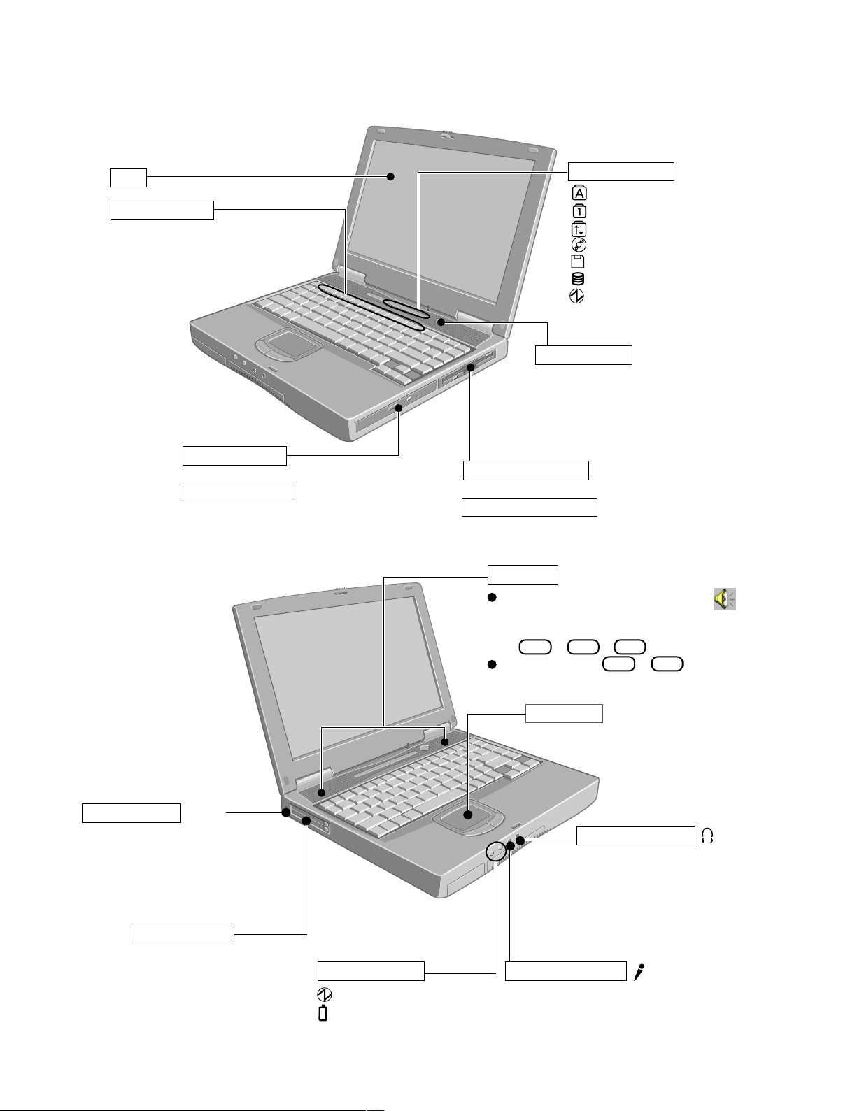
2. Names and Functions of Parts
The illustrations shown may differ from the actual physical appearances.
LCD
Function Keys
For information on the key combinations available.
CD-ROM Drive
or
DVD-ROM Drive
LED Indicators
Caps Lock
Numeric key (NumLk)
Scroll lock (ScrLk)
CD-ROM/DVD-ROM status
Floppy disk/SuperDisk status
Hard disk status
Power status
Power Switch
Before using the computer for the first time,
carefully read the [Limited Use License
Agreement]. If you agree to the conditions,
remove the seal.
Floppy Disk Drive
or
SuperDiskTM Drive
*1
SuperDiskTM and SuperDisk logo are trademarks of
Imation Corp.
*1
Speakers
To adjust the volume
*2
, select the on the task
bar, then [Volume Control].
*2
You may also use the function keys to perform this operation
(
Fn + F5
or
F6
).
Speaker on/off : Fn + F4
Security Lock
LOCK
A Kensington cable can be connected to prevent theft of your
computer. For more information, please read the manual that
comes with the cable.
PC Card Slots
LED Indicators
Power status
Battery pack status
Touch Pad
Headphone Jack
Use this connector to connect
headphones or amplifier-equipped
speakers. Audio output from the
internal speaker is disabled when
headphones or external speakers
are connected.
Microphone Jack
Use only a monaural condenser microphone.
Using an input source other than a monaural
condenser microphone may not allow audio to
be input or may damage the equipment.
2 - 1

USB Port
DC-IN Jack
Parallel Port
External Keyboard/Mouse Port
Ventilation Hole
These holes allow heat to exit.
CAUTION
Do not block or place the computer in a location that may prevent proper ventilation.
Expansion Bus Connector
External Display Port
Serial Port
Internal Modem
or
Internal Modem & LAN Port
CAUTION
This cover is not to be opened by anyone
except authorized service personnel.
Battery Pack
RAM Module Slot
2 - 2
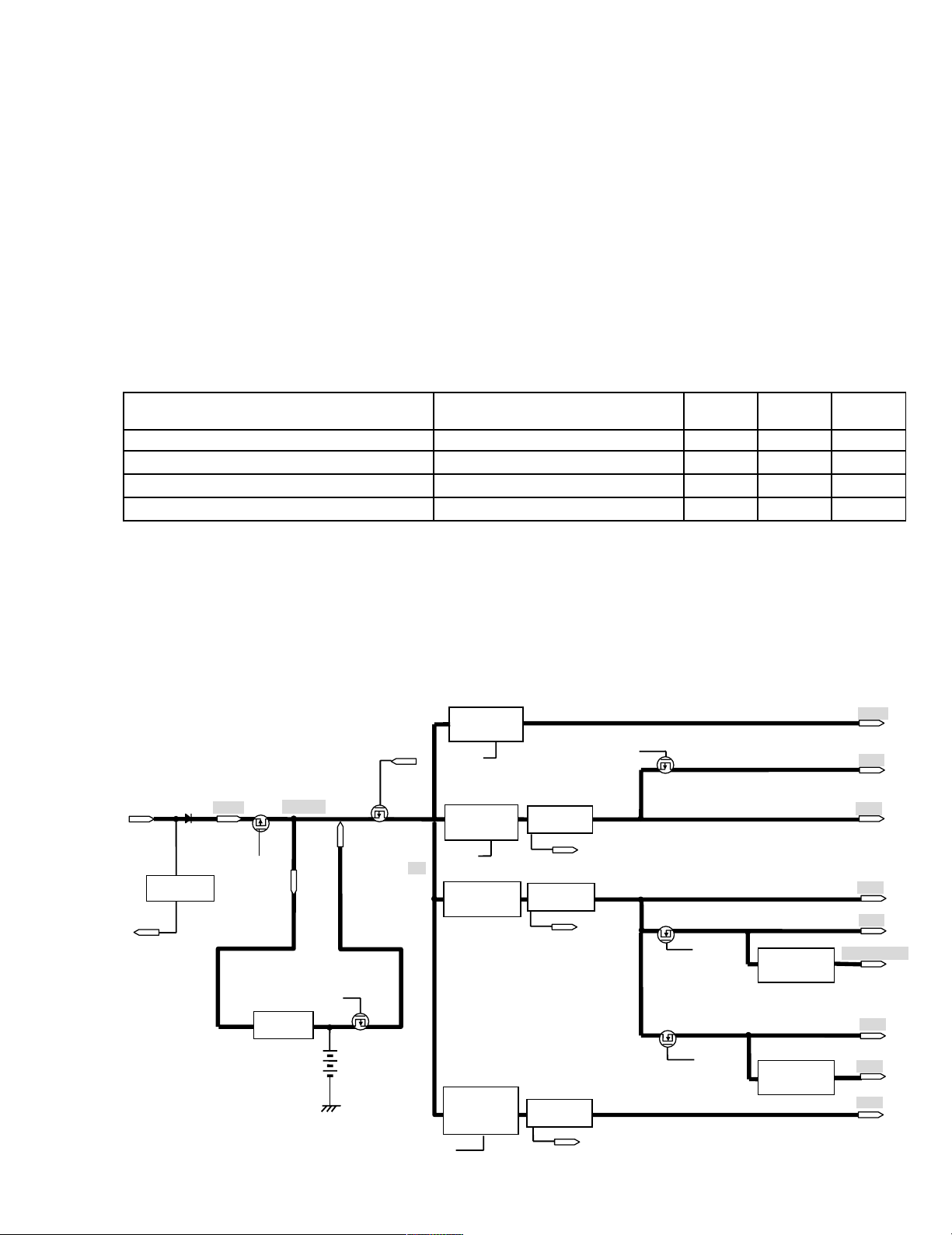
3.Technical Information
3.1 System Overview
3.1.1 System Configuration
The main system is made up of a Main board, a SUB board, a Jack board, a LED board, a IF switch board,
a PAD board and a COM board.
The power circuit has voltage for individual 1.6V/2.5V/3.3V/5V/12V.
It also supports both mixed-voltage LSIs at 3.3V/5V and single-voltage LSIs at 3.3V.
The CPU operates at 1.6V, 1.35V(core)/2.5V; the main memory at 3.3V; the core logic at 3.3V/5V; and the
other main chips at 3.3V.
3.1.2 Power Supply System
The power supply used by the Main board is generated on the Main board based on the voltage from the AC adapter.
Power Supply System Description On mode
VC system (VC5, VC3, VC25, VC16, VC15)
CPU and logic power supply ON OFF OFF
Suspend
mode
VB system (VB5, VB3) Logic power supply ON ON OFF
VA system (VA3) PMC power supply ON ON ON
VPP system (VPP) 12V power supply, for the card slot ON OFF OFF
Table 1: Description of Power Supply Systems
Power is supplied to the AC adapter and battery pack in that order when the RTC power is off or is in
suspend mode. When neither power supply can be accessed, power is supplied from the clock battery
(RTC battery).
Block Diagrams
Power Supply Configuration Diagram
IC43
VOLTAGE
REGULATOR
VM1
OUTPUT12V
VD12ON
IC58
DC/DC
CONVERTER
OUTPUT 5V
SUSB
IC58
DC/DC
CONVERTER
OUTPUT 3.3V
IC57
DC/DC
CONVERTER
OUTPUT
1.6V /1.35V
VOLTAGE
DETECTOR
OVERVOL
VOLTAGE
DETECTOR
OVERVOL
VOLTAGE
DETECTOR
SUSB
SUSC*
SUSB*
IC16
VOLTAGE
REGULATOR
OUTPUT 2.5V
IC46
VOLTAGE
REGULATOR
OUTPUT 1.5V
AC ADAPTOR 15.6V
VOLTAGE
DETECTOR
AC IN*
Q70
AC15
AC ON
IC44
BATTERY
CHARGER
Li-Ion BATTERY
11.1V
5400mAh
OVERVOL
SYSPW
Q62
ACVOK
Q72
Off/Hiber
nation
VD12
VC5
VB5
VA3
VB3
VGA_CORE
VC3
VCT
VC1
SUSB*
OVERVOL
3 - 1
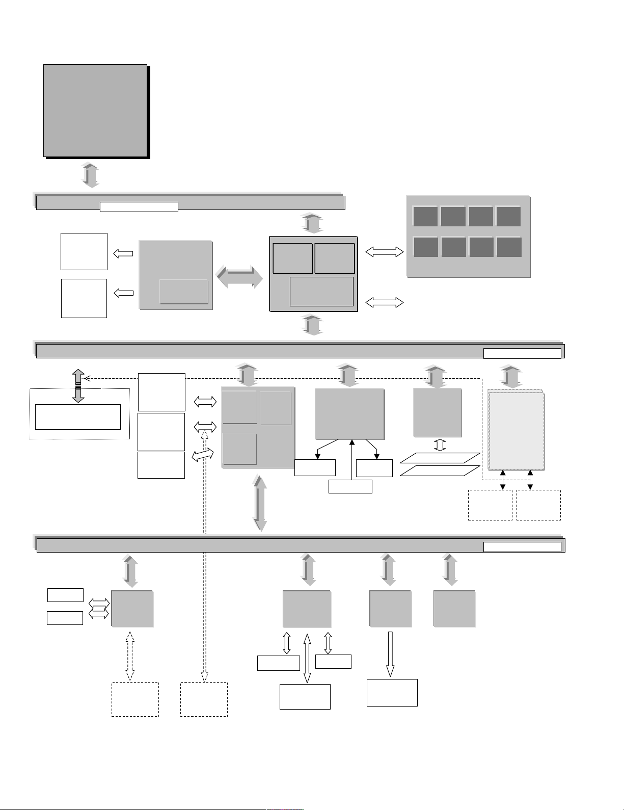
System Configuration Diagram
l
l
ll
int
int
intint
e
e
ee
Mobile
Pentium III
h
wwwwwiiiiittttthhhh
Intel
®
SpeedSt ep
TM
Techn ol ogy
64bit Host Bus
1.5V (GTL)
LCD
14.1”/13.3”
CRT
Portreplicator
Rage Mobility M1
Rage Mobility M1
Rage Mobility M1Rage Mobility M1
ATI
ATI
ATIATI
VRAM
8.0MB
HDD
20/10GB
2.5 inch
CD-ROM
DRIVE
X24max
USB
DEVICES
Secondary
VGA
VGA
VGAVGA
Primary
AGP Bus
IDE
Interface
USB
Interface
PCI ISA
Bridge
PIIX4M
PIIX4M
PIIX4MPIIX4M
INTEL
Host PCI
Bridge
Interface
443BX
443BX
443BX443BX
INTEL
Headphone
DRAM
SOUND
SOUND
SOUNDSOUND
ES1988 ESS
Ext. MIC
Speaker
Main Memory(SDRAM)
Main Memory(SDRAM)!!!! 64M/128MB
Main Memory(SDRAM)Main Memory(SDRAM)
Extension Memory
Extension Memory
Extension MemoryExtension Memory
(SDRAM)
(SDRAM)
(SDRAM)(SDRAM)
~
256MB
256MB
256MB256MB
PCMCIA
PCMCIA
PCMCIAPCMCIA
II
RB5C478
RICOH
RICOH
RICOHRICOH
TYPE II(SLOT A)
TYPE II(SLOT B)
64M/128MB
64M/128MB64M/128MB
3.3V
32bit PCI Bus
RJ11
Connecter
MODEM
MODEM
MODEMMODEM
COMBO
COMBO
COMBOCOMBO
MiniPCI
or
or
oror
Connecter
RJ45
3.3V
Serial
Parallel
Super I/O
Super I/O
Super I/OSuper I/O
PC97338
NS
FDD
16/8bit ISA/EIO Bus
16/8bit ISA/EIO Bus
BIOS
KBC
KBC Embedded
KBCKBC
PS/2 Port
Super
or
Disk
Drive
Flat PAD
Int. KB
Embedded
EmbeddedEmbedded
Controller
Controller
ControllerController
Li-Ion
Battery Pack
BIOS
BIOSBIOS
FlashROM
512KB
3 - 2
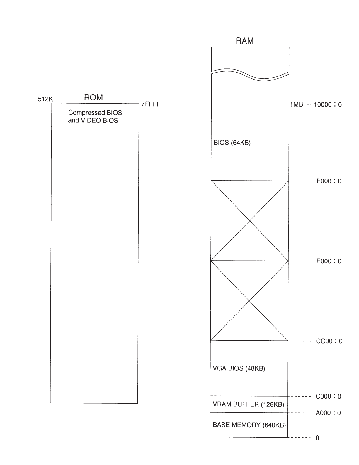
3.2 System Memory Map
3 - 3
I/O Address Map (CF-48)
,
r
y
g
y
)
y
)
)
)
)
)
)
)
)
)
)
)
)
r
Address Function IC No
x0000 - x000F Direct memory access controller
x0010 - x0018 Motherboard resources
x001F - x001F Motherboard resources
x0020 - x0021 Programmable interrupt controller
x0022 - x0022 Motherboard resources
x0024 - x0025 Motherboard resources
x0028 - x0029 Motherboard resources
x002C - x002D Motherboard resources
x0030 - x0031 Motherboard resources
x0034 - x0035 Motherboard resources
x0038 - x0039 Motherboard resources
x003C - x003D Motherboard resources
x0040 - x0043 System time
x0050 - x0052 Motherboard resources
x0060 - x0060 Standard 101/102-Key or Microsoft Natural Keyboard
x0061 - x0061 System speaker
x0062 - x0062 Motherboard resources
x0064 - x0064 Standard 101/102-Key or Microsoft Natural Keyboard
x0066 - x0066 Motherboard resources
x0070 - x0071 S
x0072 - x0077 Motherboard resources
x0080 - x0080 Motherboard resources
x0081 - x008F Direct memory access controller
x0090 - x009F Motherboard resources
x00A0 - x00A1 Pro
x00A4 - x00A5 Motherboard resources
x00A8 - x00A9 Motherboard resources
x00AC - x00AD Motherboard resources
x00B0 - x00BD Motherboard resources
x00C0 - x00DF Direct memory access controller
x00F0 - x00FF Numeric data processor
x0170 - x0177 Intel 82371AB/EB PCI Bus Master IDE Controller
x0170 - x0177 Secondar
x01B0 - x01B1 Motherboard resources
x01F0 - x01F7 Intel 82371AB/EB PCI Bus Master IDE Controller
x01F0 - x01F7 Primar
x0376 - x0376 Intel 82371AB/EB PCI Bus Master IDE Controller
x0376 - x0376 Secondary IDE controller (dual fifo
x0378 - x037F ECP Printer Port (LPT1
x0398 - x0399 Motherboard resources
x03B0 - x03BB RAGE MOBILITY AGP (English
x03C0 - x03DF RAGE MOBILITY AGP (English
x03F0 - x03F5 Standard Floppy Disk Controller
x03F6 - x03F6 Intel 82371AB/EB PCI Bus Master IDE Controller
x03F6 - x03F6 Primary IDE controller (dual fifo
x03F7 - x03F7 Standard Floppy Disk Controller
x03F8 - x03FF Communications Port (COM1
x04D0 - x04D1 Motherboard resources
x0778 - x077F ECP Printer Port (LPT1
x0CF8 - x0CFF PCI bus
x1000 - x103F Motherboard resources
x1040 - x104F Motherboard resources
x1050 - x1057 Primary IDE controller (dual fifo
x1050 - x105F Intel 82371AB/EB PCI Bus Master IDE Controller
x1058 - x105F Secondary IDE controller (dual fifo
x1060 - x1067 Lucent Win Modem
x1400 - x14FF ESS Allegro PCI Audio (WDM
x1800 - x18FF Lucent Win Modem
x2000 - x20FF RAGE MOBILITY AGP (English
x2000 - x2FFF Intel 82443BX Pentium(r) II Processor to AGP controlle
xFE00 - xFE01 Motherboard resources
stem CMOS/real time clock
rammable interrupt controller
IDE controller (dual fifo
IDE controller (dual fifo
3 - 4
4. Diagnosis Procedure
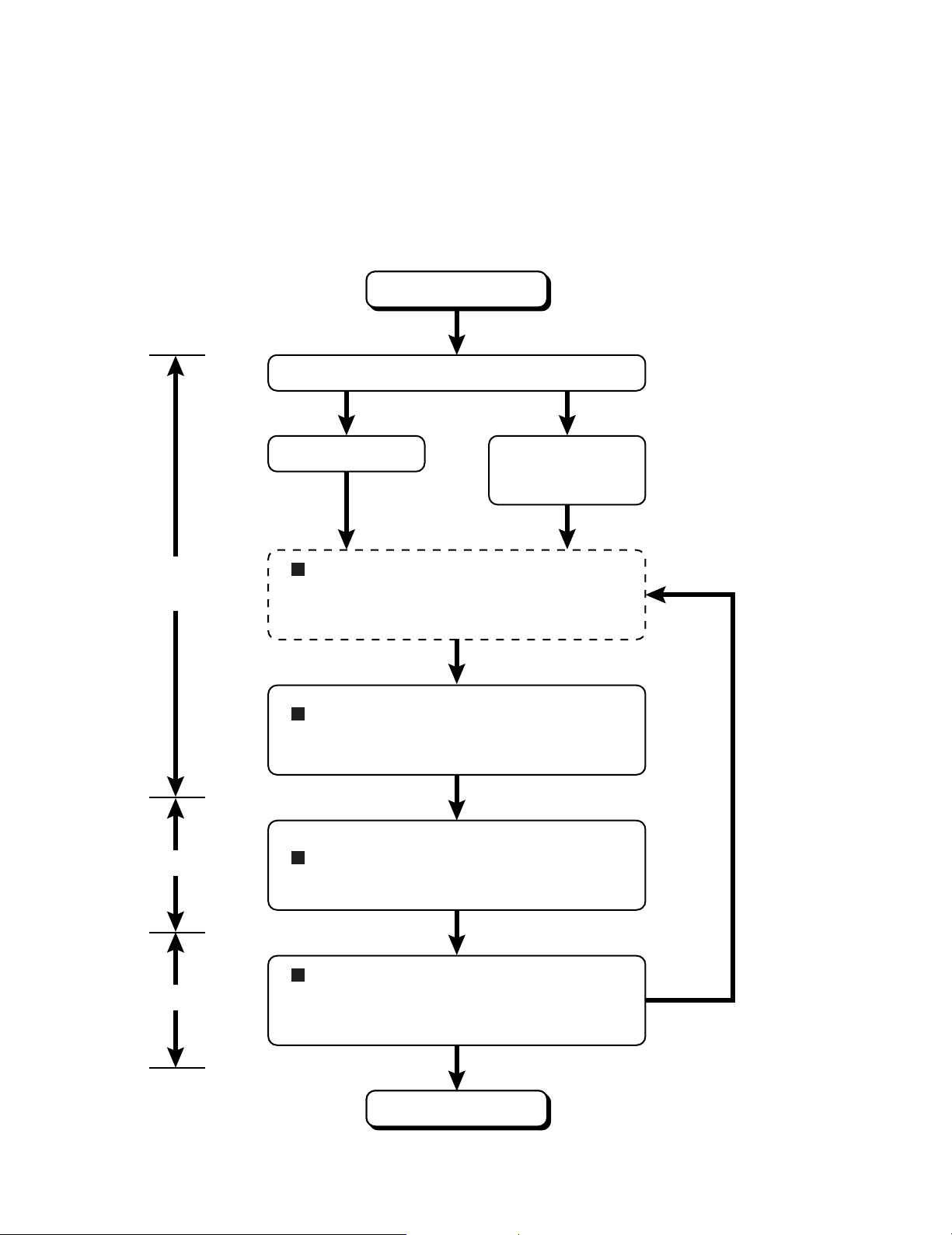
4.1. Basic Procedures
The basic procedures for diagnosis, disassembly, and test of defective parts of a set to be repaired are summarized below. For
details, refer to relevant pages in the Service Manual.
ll
l Flow Chart
ll
OCCURRENCE OF
TROUBLE
Power sw is set to ON.
DEFECTIVE PARTS
SORTING
Power On Self Test
POST NORMAL
FINISH POST ERROR
OCCURRENCE
SELF-DIAGNOSIS TEST (IF REQUIRED)
Conduct a self diagnosis test when
it is necessary for conduct
trouble diagnosis.
TROUBLESHOOTING
Defective parts are sorted by
referring to symptoms.
Automatic diagnosis takes
place when the power switch
is set to ON.
REPAIR WORK
INSPECTION
DISASSEMBLY PROCEDURE
Replace defective parts.
SELF-DIAGNOSIS TEST
After repair, conduct a selfdiagnosis test and make sure that the
repaired set operates properly.
TEST OK
END OF
REPAIR WORK
4 - 1
TEST FAILED
4.2. Power-On Self Test (Boot Check)
4.2.1. Outline of POST
The set has a boot check function called POST (Power-On Self Test) in it. The condition of the main body is diagnosed by checking
beep sound or error code.
l Start .............Test begins automatically when power switch is set to ON.
l Normal finish .....After memory checking, a beep sound is issued once and the set is placed into automatic stop.
Note: If no error occurs, nothing is displayed. (No display of OK, etc.)
4.2.2. Error Diagnosis by Checking Beep Signal Sound
The beep sound is as follows:
(1 (long sound) -2-3-4)
(Length of bar shows length of sound.)
= long sound (about 0.4 sec.),
l Table of errors classified by beep sounds
Diagnosis Beep signal sound Error message
Main board
(Note) A beep sound is also issued in case of other I/O trouble.
1(long sound)-2 BIOS ROM error
1-2-2-3
1-3-1-1
1-3-1-3
1-3-4-1
1-3-4-3
1-4-1-1
= short sound (about 0.2 sec.), Length between sounds is about 0.1 sec.
BIOS ROM error
RAM error
Keyboard controller error
RAM error
RAM error
RAM error
BIOS ROM error2-1-2-3
Occurrence of unexpected offering2-2-3-1
4 - 2
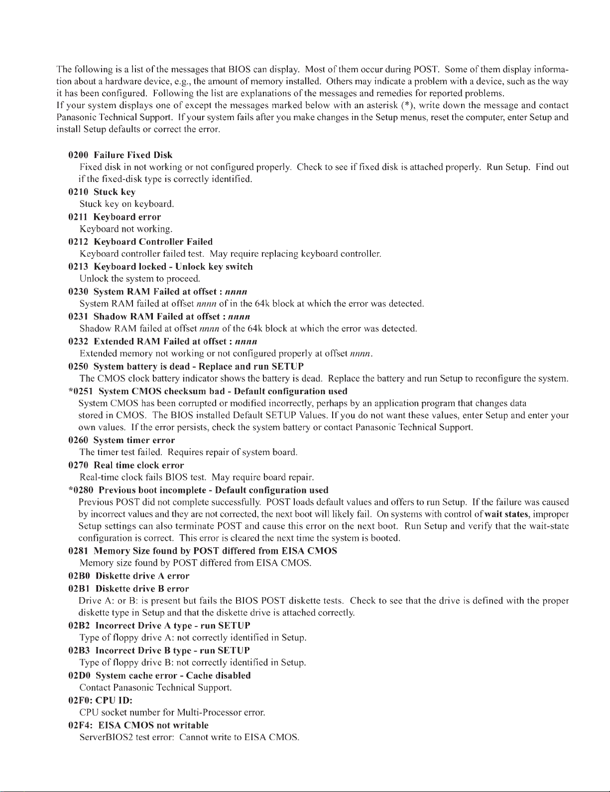
4.3. List of Error Codes
4 - 3
4 - 4
4.4. Diagnosis Map
4.4.1. MAIN UNIT DIAGNOSIS (1/2)
Make sure that connecting cables, connectors and AC adapter are not loose or disconnected prior to testing.
No. Symptom
1
No power is sent to the
unit.
(when using AC)
No power is sent to the
unit, (When using the
Battery Pack)
2
Power cuts off during
operation.
Troubleshooting
No.
1-1
1-2
1-4
1-5
1-6
1-7
1-8
2-1
procedures
Is 15V applied to pins 5-8 of
Q74? (Whichever one)?
Is 15V applied to pins 1 of
Q74?
Is 15V applied to pins 1 of
Q70?
Is voltage pin 4 of Q70 lower
than 1V?
Is voltage pin 4 of Q62 lower
than 1V?
Before setting the power
switch to ON, check voltage
on either side of R260. Is
Voltage 3.3V?
Final Means
Is 8~12V applied to pins 5~8
of Q62? (Whichever one)
Check soldered parts of
R389, 390, 403 and R404.
Source of
Result
YES Go to No. 1-6
NO Go to No. 1-2
YES Go to No. 1-5
NO Go to No. 1-3
YES Go to No. 1-4
NO
YES
NO
YES
NO
YES
NO
YES
NO Go to No. 1-5
NO
problem
If resistance
across L93
terminals is not
lower than 1
If lower than 1 D26
If voltage pin 3 of
D24 is 15V
If lower than 15V D24
If voltage pin 3 of
D24 is 15V
If lower than 15V
If voltage is 0V
during the power
switch is set to
ON, go to No. 1-7
If not 0V
If voltage of C454
is 3.3V
If lower than 3V
Main PCB IC58
Go to No. 1-6
If they show
soldered
completely
Component
L211-3
Q70
R415
Q69
Q62
Q61
D28, D29
D30, D31
SW801
R260
IC58
R389, R390
R403, R404
IC58YES
4.4.2 MAIN UNIT DIAGNOSIS (2/2)
Make sure that connecting cables, connectors and AC adapter are not loose or disconnected prior to testing.
No. Symptom
No.
1 YES Go to No. 1-2
When a device is selected
for “Boot Up Drive”, the
system boots from a
different device.
1-1
1-2
Troubleshooting
procedures
Are there system files in the
device selected?
Does the unit operate
normally after replacing the
problem device.
4 - 5
Source of
Result
NO Improper setting
YES
NO Main PCB
problem
Device for which
the problem
occurred
Component
(HDD)
IC13
(FDD/SDD)
IC13
IC23
No. Symptom
2
Date or Time cannot be
input.
Date and Time does not
change properly.
Date and Time are not
displayed.
3
Memory count is too large
or too small.
4
No Sound
Volume does not work.
5
Default configuration in
use
6 Interrupt controller failure
8
Expansion card RAM
checksum error
9 Real Time Clock failure
Troubleshooting
No.
2-1 Replace the Main PCB.
3-1 Replace the Main PCB.
4-1
4-2
4-3 Replace the Main PCB.
5-1
8-1
8-2
procedures
Check software setting.
Replace the Speakers.
Does operation return to
normal?
Does the system return to
normal if the expansion card
is removed?
Replace the expansion card.
Does operation return to
normal?
Source of
Result
YESNOSoftware setting
YESNOSpeakers
YES
YES
problem
Main PCB
Main PCB
Go to No. 4-2
Go to No. 4-3
Main PCB
ConfigurationCheck configuration.
Main PCB
Main PCB7-17 Timer failure
Go to No. 8-2
Main PCBNO
Expansion card
Main PCBNO
Main PCB IC139-1
Component
IC13
X2
RTC battery
IC5
12
IC3
IC30
IC33
IC136-1
IC13
IC3
10 Dead RTC Battery
11
CMOS Checksum error
12
Does resetting through
10-1
SETUP correct the problem?
Replace the battery.
Does operation return to
10-2
normal?
Were the correct settings
12-1
selected during SETUP?
Replace the FDD.
Does operation return to
12-2
normal?
Replace the HDD.
Does operation return to
12-3
normal?
Does resetting through
12-4
SETUP correct the problem?
YES
YES
NO
YES
NO
YES
YES
YES
Error during
SETUP
Go to No. 10-2NO
Battery
Main PCB
ConfigurationCheck configuration.11-1Configuration error
Go to No. 12-2
Go to No. 12-4
FDD
Go to No. 12-3NO
HDD
Go to No. 12-4NO
Error during
SETUP
Main PCBNO
RTC battery
IC13
IC13
X2
4 - 6
No. Symptom
13
Real time Clock is not
updating
Memory size/data error
14
15 PCI failur
4.4.3 LCD DIANOSIS
Make sure that connecting cables, connectors and AC adapter are not loose or disconnected prior to testing.
Troubleshooting
No.
13-1
14-1
15-1
15-2
procedures
Does resetting the date/time
in SETUP correct the
problem?
Replace the expansion RAM
card.
Does operation return to
normal? (Go to “NO” if not
connected.)
Does the system return to
normal if the expansion card
is removed?
Replace the expansion card.
Does operation return to
normal?
Source of
Result
YES
YES
YES
YES
problem
Error during
SETUP
Main PCBNO IC13
Expansion RAM
card
Main PCB NO
Go to No. 15-2
Main PCBNO IC3
Expansion card
Main PCB NO IC3
Component
IC3
IC5
12
No. Symptom
1
No picture appears on the
screen.
2
Display is too dark or too
bright.
3
Part of the screen does
not display properly.
Display quality poor.
(Fuzzy or slanted, etc.)
4
Backlight does not turn on.
Troubleshooting
No.
1-1
1-2
1-3
2-1
2-2
2-3
3-1
3-2
4-1
4-2
4-3
procedures
Does the LCD display
properly after brightness
level is adjusted?
Replace the LCD.
Does operation return to
normal?
Replace the Main PCB.
Does operation return to
normal?
Does the LCD display
properly after brightness
level is adjusted?
Replace the LCD.
Does operation return to
normal?
Replace the Main PCB.
Does operation return to
normal?
Replace the LCD.
Does operation return to
normal.
Replace the Main PCB.
Does operation return to
normal?
Replace the Inverter PCB.
Does operation returnt o
normal?
Replace the Inverter cable.
Does operation return to
normal?
Replace the backlight.
Does operation return to
normal?
Source of
Result
YES
NO
YES LCD
NO Go to No. 1-3
YES
NO
YES
NO
YES
NO
NO LCD cable
YES
NO
YES
NO
YES
NO
YES
NO
YES
NO
problem
Brigntness
adjustment
Go to No. 1-2
Main PCB
LCD cable
Brigntness
adjustment
Go to No. 2-2
LCD
Go to No. 2-3
Main PCBYES
LCD
Go to No. 3-2
Main PCB
LCD cable
Inverter PCB
Go to No. 4-2
Inverter cable
Go to No. 4-3
Backlight
Main PCB
Component
IC14
CN16
IC52
IC14
CN16
IC52
4 - 7
4.4.4 KEYBOARD, MOUSE or TOUCH PAD DIAGNOSIS
Make sure that connecting cables, connectors and AC adapter are not loose or disconnected prior to testing.
No. Symptom
No.
1
Key top cannot be
pressed.
Key top does not spring
back after pressing.
2
None of the keys function.
Certain keys do not
function.
3 3-1
Input character is
displayed as grabage.
4
Mouse does not function.
Inputs from the mouse are
not accepted properly.
5
Touch pad not function.
Input from the track ball
are not accepted properly.
Keyboard failure
6 Go to No. 7
7
Keyboard interface failure
2-1
3-2
3-3
4-1
5-1
5-2
6-1
7-1
Troubleshooting
procedures
Replace the keyboard and
see if inputting from the
keyboard function normally?
Does the screen mode
correspond to the key entry
mode?
Is the keyboard setting in the
operating system correct?
Replace the keyboard and
see if inputting from the
keyboard functions normally.
Replace the mouse.
Does operation return to
normal?
Replace the touch pad.
Does operation return to
normal?
Replace the touch pad FPC.
Does operation return to
normal?
Is the keyboard properly
connected?
Replace the keyboard.
Does operation return to
normal?
Result
YESNOKeyboard
YES Go to No. 3-2
NO
YES Go to No. 3-3
NO Software setting
YESNOKeyboard
YESNOMouse
YES Touch Pad
NO
YESNOTouch Pad FPC
YES
NO
Source of
problem
Keyboard1-1 Keyboard is broken.
Main PCB
Operating
mistake
Main PCB
Main PCB
Go to No. 5-2
Main PCB
Keyboard was
not connected
properly
KeyboardYES
Main PCBNO IC26
Component
IC26
IC26
IC26
4 - 8
 Loading...