

Page 1
ORDER NO. CPD0607057C3
Notebook Computer
CF-18
This is the Service Manual for
the following areas.
7 …for Asia
8 …for Argentina
Model No. CF-18KHH651 2
1: Operation System
L: Microsoft® Windows® XP Professional MUI
2: Area
7 /8: Refer to above area table
© 2006 Matsushita Electric Industrial Co., Ltd. All rights reserved.
Unauthorized copying and distribution is a violation of law.
Page 2

1
Page 3
2
Page 4
3
Page 5

CONTENTS
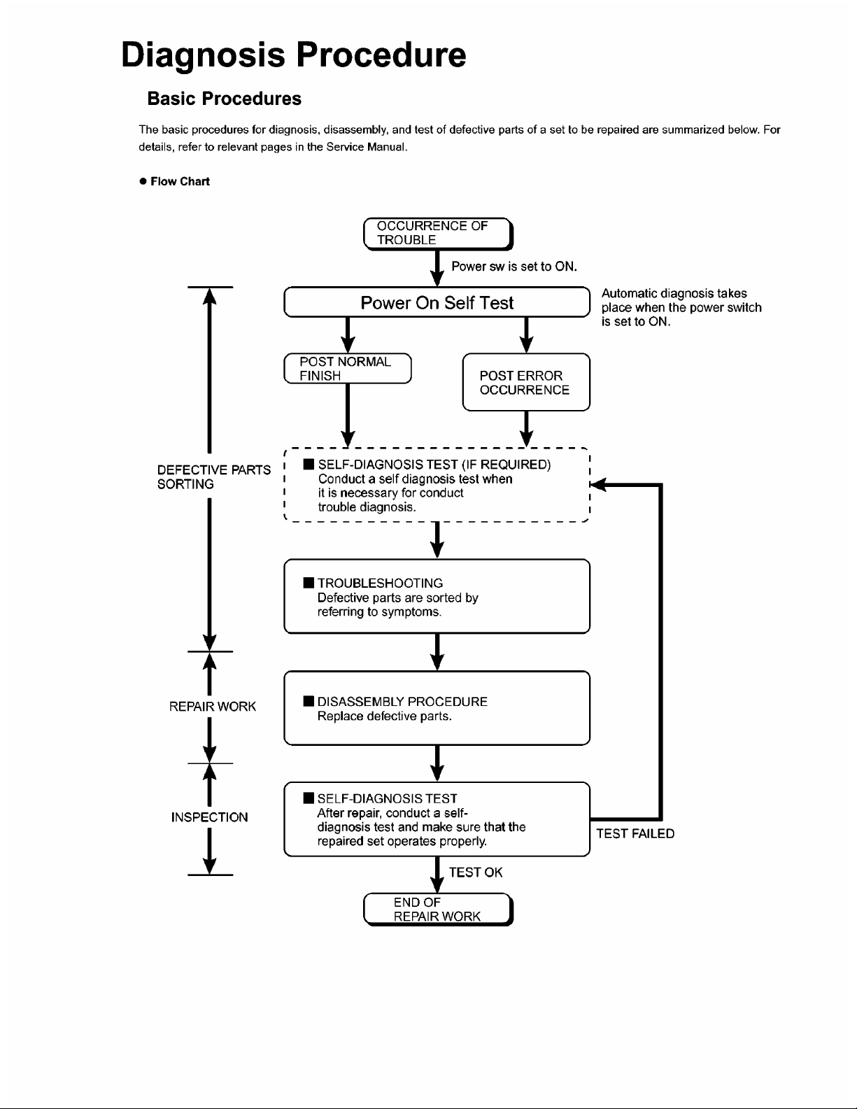
1 Diagnosis Procedure ······································································································1-1
2 Power-On Self Test (Boot Check) ··················································································2-1
3 List of Error Codes ··········································································································3-1
4 Diagnostic Test ···············································································································4-1
5 Self Diagnosis Test ·········································································································5-1
6 Wiring Connection Diagram ···························································································6-1
7 Disassembly/Reassembly ······························································································7-1
8 Exploded View ················································································································8-1
9 Replacement Parts List ··································································································9-1
Page 6
1
1-1
Page 7
2 Power-On Self Test (Boot Check)
Outline of POST
The set has a boot check function called POST (Power-On Self Test) in it. The condition of the main body is diagnosed by checking
beep sound or error code.
z Start .............Test begins automatically when power switch is set to ON.
z Normal finish .....After memory checking, a beep sound is issued once and the set is placed into automatic stop.
Note: If no error occurs, nothing is displayed. (No display of OK, etc.)
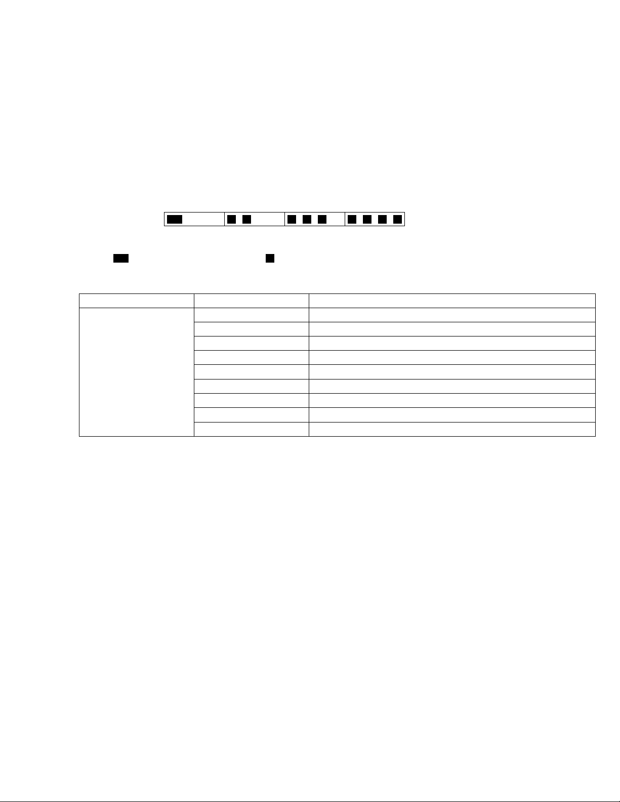
Error Diagnosis by Checking Beep Signal Sound
The beep sound is as follows:
(1 (long sound) -2-3-4)
(Length of bar shows length of sound.)
= long sound (about 0.4 sec.),
z Table of errors classified by beep sounds
Diagnosis Beep signal sound Error message
Main board
(Note) A beep sound is also issued in case of other I/O trouble.
1(long sound)-2 BIOS ROM error
1-2-2-3
1-3-1-1
1-3-1-3
1-3-4-1
1-3-4-3
1-4-1-1
= short sound (about 0.2 sec.), Length between sounds is about 0.1 sec.
BIOS ROM error
RAM error
Keyboard controller error
RAM error
RAM error
RAM error
BIOS ROM error2-1-2-3
Occurrence of unexpected offering2-2-3-1
2-1
Page 8

3 List of Error Codes
<Only when the port replicator is connected>
The following is a list of the messages that BIOS can display. Most of them occur during
POST. Some of them display information about a hardware device, e.g., the amount of memory
installed. Others may indicate a problem with a device, such as the way it has been configured.
Following the list are explanations of the messages and remedies for reported problems.
If your system displays one of except the messages marked below with an asterisk (*), write
down the message and contact Panasonic Technical Support. If your system fails after you
make changes in the Setup menus, reset the computer, enter Setup and install Setup defaults
or correct the error.
0200 Failure Fixed Disk
Fixed disk in not working or not configured properly. Check to see if fixed disk is attached
properly. Run Setup. Find out if the fixed-disk type is correctly identified.
0210 Stuck key
Stuck key on keyboard.
0211 Keyboard error
Keyboard not working.
0212 Keyboard Controller Failed
Keyboard controller failed test. May require replacing keyboard controller.
0213 Keyboard locked - Unlock key switch
Unlock the system to proceed.
0230 System RAM Failed at offset : nnnn
System RAM failed at offset nnnn of in the 64k block at which the error was detected.
0231 Shadow RAM Failed at offset : nnnn
Shadow RAM failed at offset nnnn of the 64k block at which the error was detected.
0232 Extended RAM Failed at offset : nnnn
Extended memory not working or not configured properly at offset nnnn.
0250 System battery is dead - Replace and run SETUP
The CMOS clock battery indicator shows the battery is dead. Replace the battery and run Setup
to reconfigure the system.
*0251 System CMOS checksum bad - Default configuration used
System CMOS has been corrupted or modified incorrectly, perhaps by an application program
that changes data stored in CMOS. The BIOS installed Default SETUP Values. If you do not
want these values, enter Setup and enter your own values. If the error persists, check the system
battery or contact Panasonic Technical Support.
0260 System timer error
The timer test failed. Requires repair of system board.
0270 Real time clock error
Real-time clock fails BIOS test. May require board repair.
*0280 Previous boot incomplete - Default configuration used
Previous POST did not complete successfully. POST loads default values and offers to run
Setup. If the failure was caused by incorrect values and they are not corrected, the next boot
will likely fail. On systems with control of wait states, improper Setup settings can also terminate POST and cause this error on the next boot. Run Setup and verify that the wait-state
configuration is correct. This error is cleared the next time the system is booted.
0281 Memory Size found by POST differed from EISA CMOS
Memory size found by POST differed from EISA CMOS.
3-1
Page 9

02D0 System cache error - Cache disabled
Contact Panasonic Technical Support.
02F0: CPU ID:
CPU socket number for Multi-Processor error.
02F4: EISA CMOS not writable
ServerBIOS2 test error: Cannot write to EISA CMOS.
02F5: DMA Test Failed
ServerBIOS2 test error: Cannot write to extended DMA (Direct Memory Access) registers.
02F6: Software NMI Failed
ServerBIOS2 test error: Cannot generate software NMI (Non-Maskable Interrupt).
02F7: Fail - Safe Timer NMI Failed
ServerBIOS2 test error: Fail-Safe Timer takes too long.
device address Conflict
Address conflict for specified device.
Allocation Error for: device
Run ISA or EISA Configuration Utility to resolve resource conflict for the specified device.
Failing Bits : nnnn
The hex number nnnn is a map of the bits at the RAM address which failed the memory test.
Each 1 (one) in the map indicates a failed bit. See error 230,231 or 232 for offset address of the
failure in System, Extended or Shadow memory.
Invalid System Configuration Data
Problem with NVRAM (CMOS) data.
I/O device IRQ conflict
I/O device IRQ conflict error.
Operating System not found
Operating system cannot be located on either drive A: or drive C:. Enter Setup and see if fixed
disk and drive A: are properly identified.
Parity Check 1 nnnn
Parity error found in the system bus. BIOS attempts to locate the address and display it on the
screen. If it cannot locate the address, it displays ????. Parity is a method for checking errors
in binary data. A parity error indicates that some data has been corrupted.
Parity Check 2 nnnn
Parity error found in the I/O bus. BIOS attempts to locate the address and display it on the
screen. If it cannot locate the address, it displays ????.
Press <F1> to resume, <F2> to Setup
Displayed after any recoverable error message. Press <F1> to start the boot process or <F2> to
enter a Setup and change the settings. Write down and follow the information shown on the
screen.
Troubleshooting
3-2
Page 10

4 Diagnostic Test
Diagnostic Test Procedure
4.1. Equipment
(1)
Test Computer --------------------------------------------------------------------------
(2)
External Floppy Disk Drive (USB Port) ------------------------------------------
(3)
AC Adapter -----------------------------------------------------------------------------
(4)
Loopback Plug (Serial Port Test for RS232C) [P/N: DFWV95C0067] ----
(5)
Floppy Disk containing file DIAG ---------------------------------------------------
4.2. Preparation
(1)
Connect the AC Adapter and External Equipments.
(2)
The System Setup should be set to the factory setting values by executing the "SETUP UTILITY"
which can be invoked by F2 key at the POST.
If not, the messages and items of the diagnostic test may not be displayed properly on the LCD.
(3)
The serial port must be enabled in the "SETUP UTILITY" in order to execute the "1st SERIAL
PORT" test.
(4)
Connect the serial loopback plug.
1 unit
1 unit
-
1 pc.
1 pc.
-
1 pc.
-
4-1
Page 11
5 Self Diagnosis Test
Floppy disk is Included for the self-diagnostic tests that should be performed before using this product.
Important notice
1. System password
If the password function has been turned on, you will need to ask the user for the password
before performing the self-diagnostics.
2. FDD test
Performing the FDD test will erase the contents of the floppy disk you insert into the drive. Use
a formatted disk that has no contents or whose contents are not required. This product has a
password function. However, if this function is turned on, the self-diagnostics tests will not work.
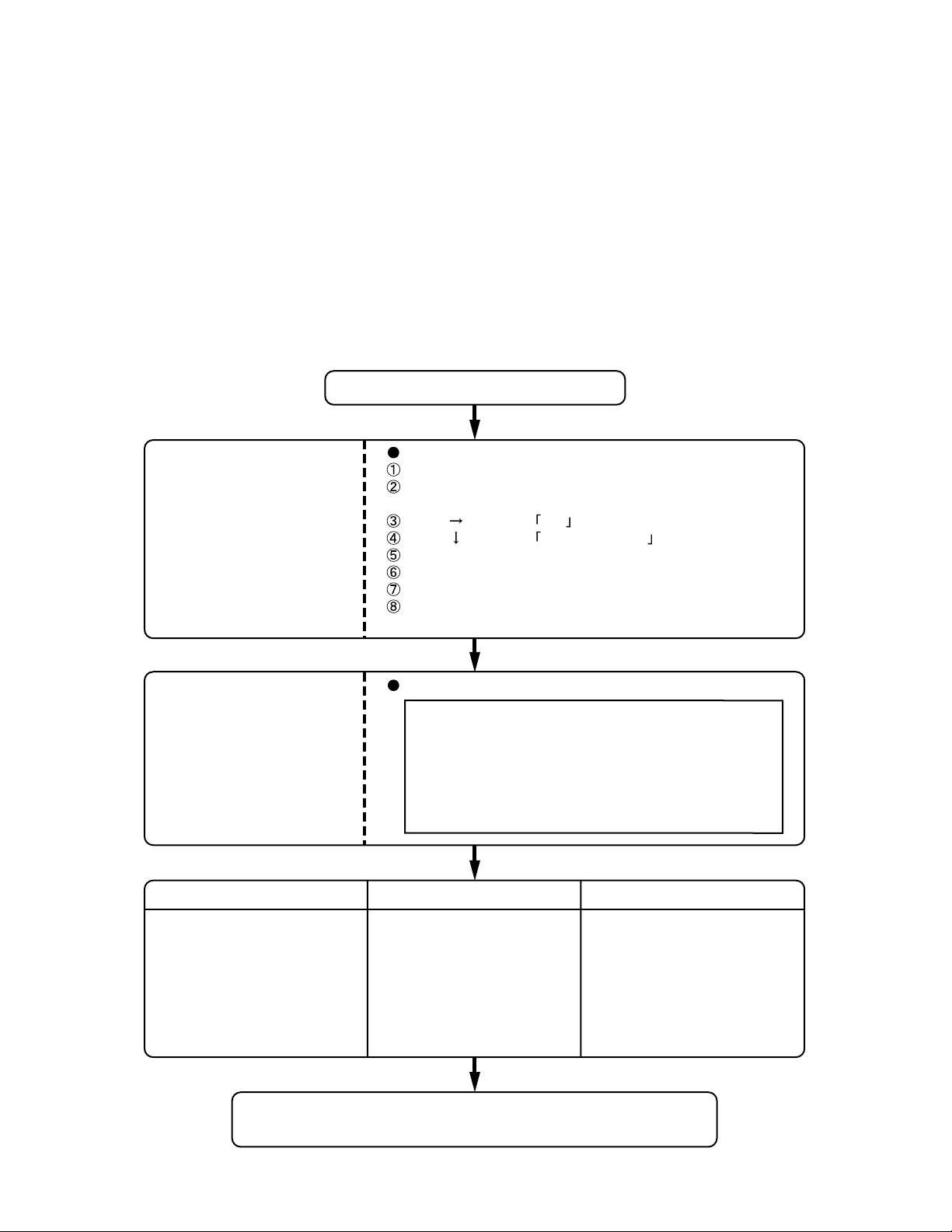
5.1. Outline of Self Diagnostic Tests
Insert the diagnostics floppy disk
Starting up the setup utility
Turn on the power.
When "Panasonic Press F2 to enter setup" appears
on the screen, press F2.
Return the setup
contents to default
Press " " to select Exit
Press " " to select Get default value
Press Enter.
Choose Yes for "Load default Configuration now?"
Select "Save Values & Exit" and press Enter.
Choose Yes for "Save Configuration changes and exit now?"
and press Enter.
Choose test from
the menu screen
to start the test.
Caution:
After completing repairs, be sure
to carry out the Automatic test
and Peripheraltest.
Menu Screen
1. DIAG on FD (CF-18 XP/2000 Model
2. DIAG on FD (CF-18 T ab let Model
3. LAN Test
4. Modem Test
5. Wireless LAN test (Wireless LAN Model only
6. Button Test
Q. Quit
Select please [ 1, 2, 3, 4, 5, 6, Q ] ?
)
)
)
<Automatic test> <Peripheral test> <Test selection>
Tests selected (O) from the test
item list will be performed in
succession.
DIAG on FD
Problems in the unit are located and divided according
to error messages that occur during testing.
The parallel port and CD-ROM
drive can be tested.
(See 5.3 for details.)
3. LAN Test
4. Modem Test
5. Wireless LAN test (Wireless LAN Model only
6. Button Test
)
Specifc tests required can
be freely selected and
performed from the test item
list.
Be sure to carry out the Selection
test only when necessary.
5-1
Page 12

5.1.1 List of main test items
The Selection item displays the items selected under Automatic test. If you select Automatic test, these test items
will be performed automatically. You can use Selection test to choose items from the menu screen that you want to
have tested.
These items are shown below.
1
2
CPU
3
(CPU related)
4
5
RAM (Memory related)
6
CONTROL
7
(Control ICs on the main
8
board, etc.)
9
10
11
12
13
14
15
16
IO
17
(Input-output)
18
COMMUNICATION
19
20
21
AUX
22
(Auxiliary functions)
23
24
VIDEO
25
(Display related)
26
DISK
27
(FDD, HDD)
28
UNIQUE
29
(Individual functions)
30
31
SPEAKER TEST Speaker test
VESA MODE TEST VESA mode test
A20 GATE TEST Address A20 line
CACHE ON/OFF TEST Cache memory on/off test
NPU OPERAND TEST Floating point processor function test
RAM STANDARD TEST Memory standard test
DMA PAGE REG TEST DMA page register test
DMA REGISTER TEST DAM register test
DMAC TRANSFER TEST DAM transfer test
PIC HALT INSTRUCTION TEST Interrupt controller halt instruction test
PIC REGISTER TEST Interrupt controller register test
RTC CMOS RAM TEST Real time clock CMOS test
RTC TEST Real time clock test
PIT CH0 TEST interrupt timer CH0
PIT CH1 TEST interrupt timer CH1
PIT CH2 TEST interrupt timer CH2
KEYBOARD REG TEST Keyboard test
PS/2 MOUSE REG Mouse registration test
SERIAL WRAP TEST Serial loop back (jig required)
SERIAL ALL INTERNAL TEST Serial port interior test
PARALLEL REGISTER R/W Parallel register R/W test
PCIC ALL TEST PCIC test
Card Bus Reg Card Bus register test
USB Reg USB register test
VGA ALL TEST VGA test
SVGA RAM TEST SVGA RAM test
FD WT/RD/WP TEST FD WT, RD WP test
HDD ALL TEST Only HDD lead test selected
ECP REGISTER R/W ECP register R/W test
EPP REGISTER R/W EPP register R/W test
EXT. CMOS R/W TEST Extension CMOS R/W test
Test function settings
5.2. Automatic Test
Test execution
From the menu screen shown below For Celeron models Select and press Enter for DIAG on FD
Test condition save/play
Test automatic execute
Error display (Paging style)
1. DIAG on FD (CF-18 XP/2000 Model
2. DIAG on FD (CF-18 T ab let Model
Following file command
Test executed on run settings by selecting command
Select displayed items Error, Log, Option
)
)
3. LAN Test
4. Modem Test
5. Wireless LAN test (Wireless LAN Model only
6. Button Test
Q. Quit
Select please [ 1, 2, 3, 4, 5, 6, Q ] ?
menu screen
5-2
)
Page 13

Speaker test, VESA test
The speaker test involves listening to music and choosing OK or Not okay. The VESA test involves looking at
the display to see if it is satisfactory then choosing OK or Not okay.
Serial loop back test
The Automatic test’s initial settings are set so that the serial loop back test will be executed. Connect the serial
loop back jig and then perform the test.
(This test is not executed on default mode)
Diagnostics result
If no errors occur. The screen shows the word "Pass" in large letters.
If errors occur. The test is stopped when an error occurs and the error message is displayed.
For explanations of error messages, see Error Messages and Problem Categories (section 5.5).
Quitting the test
At the screen shown below, simultaneously press the ALT and X keys.
5.3. Peripheral Test
Test execution
From the menu screen shown below, be sure to choose the following items and press Enter.
3. LAN Test
4. Modem Test
5. Wireless LAN Test
(
Wireless LAN Model only.
This test checks for internal LAN device.
Choose LAN test and press Enter.
Input screen
1. DIAG on FD (CF-18 XP/2000 Model
2. DIAG on FD (CF-18 Tablet Model
3. LAN Test
4. Modem Test
5. Wireless LAN test (Wireless LAN Model only
6. Button Test
Q. Quit
Select please [ 1, 2, 3, 4, 5, 6, Q ] ?
menu screen
)
)
)
)
5-3
Page 14

5 .4. Test Selection
Starting up the input menu
1. From the menu screen shown below, choose Quit and press Enter.
1. DIAG on FD (CF-18 XP/2000 Model
2. DIAG on FD (CF-18 T ab let Model
3. LAN Test
4. Modem Test
5. Wireless LAN test (Wireless LAN Model only
6. Button Test
Q. Quit
Select please [ 1, 2, 3, 4, 5, 6, Q ] ?
menu screen
2. When A: \DIAG appears, input "JDG_184" and press Enter.
3. The input screen shown below will appear.
To choose menu items, hold down "ALT" and press the selection key.
)
)
)
5-4
Page 15

Example:
"ALT" + "F" brings up the File menu.
Order of test flow selection
Input screen
Input screen startup
1. Reading the test conditions settings file
Press "AL T" and "F".
Press "L".
Press "AL T" and "C".
2. setting the test items
Press "AL T" and "S".
Press "S".
Choose the test item and press Enter .
Choose the test whose settings are
to be changed, press "A" for Additional
and "R" for Erase.
All initial V Alues are "0" so set
tests other than the necessary ones to "1".
Press "C" twice to return the menu screen.
To save the selected list, press "AL T" and "F" at the file menu.
Starting the test
Press "AL T" and "R".
Press "R".
This will start the test.
If the test condition settings
file is not read, this means
the test program is not running correctly .
Saving selected test items
If you change the file name when
saving the file in step
create test condition settings for
custom test items.
Example:
CF-18 .
, you can
TEST1.
End of test
5-5
Page 16

5.5 . Error Messages and Troubleshooting
The table below explains the parts that may be faulty or damaged should an error message occur while performing the
various test items of the self diagnostics program.
Test classification Screen display test items Contents
1
CPU
2
(CPU related)
3
4 RAM (Memory related)
5
CONTROL
6
(Control ICs on the
7
main board, etc.)
8
9
10
11
12
13
14
15
16
IO
17
(Input-output)
18
COMMUNICATION
19
20
AUX
21
(Auxiliary functions)
22
VIDEO
23
(Display related)
24
25
DISK
26
(FDD, HDD)
27
UNIQUE
28
(Individual functions)
29
A20 GATE TEST Address 20 line
CACHE ON/OFF Cache memory on/off
NPU OPERAND TEST Floating point processor function
RAM STANDARD Memory standard
DMA PAGE REG TEST DMA page register
DMA REGISTER TEST DAM register
DMAC Transfer TEST DAM transfer test
PIC HALT INSTRUCTION TEST Interrupt controller
PIC REGISTER TEST Interrupt controller
RTC CMOS RAM TEST Real time clock CMOS
SPEAKER TEST Speaker
PIT CH0 TEST Interrupt timer CH0
PIT CH1 TEST Interrupt timer CH1
PIT CH2 TEST Interrupt timer CH2
KEYBOARD REG TEST Keyboard
PS/2 MOUSE REG Mouse
SERIAL WRAP TEST Serial loop back (jig required)
SERIAL ALL INTERNAL TEST Serial port
PARALLEL REGISTER R/W Parallel register
PCIC ALL TEST PCIC
Card Bus REG Card Bus port
USB REG USB port
VGA ALL TEST VGA
SVGA RAM TEST SVGA RAM
VESA MODE TEST VESA mode
FD WT/RD/WP TEST FD write/read/write protection
HDD ALL TEST Only HDD lead selected
ECP REGISTER R/W Parallel port
EPP REGISTER R/W Parallel port
EXT. CMOS R/W TEST Extension CMOS R/W test
5-6
Page 17

6 Wiring Connection Diagram
MIC
H/P
JK902
JK901
CN900
CN902
CN901
AUDIO PCB
KEYBOARD
CN16
CN27
I/O PCB
RTC
BATTERY
CN17
CN5
EXTERNAL
DISPLAY
PORT
CN880
CN8
CN24
CN880
CN18
CN11
CN25
SERIAL PORT
CN881
CN883
CN9CN3
JK880
DC-IN
CN14
INVERTER PCB
CN1
CN2
TS PS2 PCB
CN901
CN900
CN6
CN7
CN891
BACK LIGHT
LCD
Touch
Screen
Panel
I/F PCB
CN850
USB PORT
USB PORT
SD PCB
CN890
MODEM
PORT
MODEM PCB
PAD PCB
SW PCB
J1
J2
CN801
CN800
HDD
MAIN
BATTERY
PMCIA UNIT
CN950
CN4
CN15
MAIN PCB
CN37
CN23
TOUCH PAD
CN35
CN802
CN12
CN21
CN30
POWER
LED PCB
SW4
GPRS
LAN PORT
SPEAKER
J1
WIRELESS
MODULE
ANT PCB
CN1
CN2
CN3
J5
J6
CN4
CN5
CN841
LANAUX
LANMAIN
6-1
Page 18

7. Disassembly/Reassembly
NOTE:
Power off the computer. Do not shut down to the Suspend or
Hibernation mode.
Do not add peripherals while the computer ius in the Suspend
or Hibernation mode; abnormal operation may result.
For the Screw tightening torque, please refer to [ 8. Exploded
View].
7.1. Removing the Battery Pack and
HDD Pack
7.2. Removing the Touch Pad and
Keyboard
KBD Plate
<B>
<B>
Palm Rest Ass'y
KBD Plate
<B>
<B>
1
2
Battery Pack
Figure 1
1. Open the Battery Cover.
2. Remove the Battery Pack.
3. Open the HDD Cover.
4. Remove the HDD Pack.
HDD Case B
HDD FPC
3
HDD Pack
Hooks
Figure 3
1. Remove the Palm Rest Assíy.
2. Remove the four Screws. <B>
3. Remove the KBD Plate.
1
2
Keyboard
Figure 4
4. Remove the Keyboard.
<C>
HDD
Hooks
Heater
<A>
<A>
HDD Case A
Figure 2
5. Remove the two Screws. <A>
6. Remove the HDD Case A and the HDD Case B.
7. Remove the HDD.
Screw<A>: DFHE5025XA
7-1
KBD
Connector
Cover
Figure 5
5. Remove the three Screws. <C>
6. Remove the KBD Connector Cover.
Page 19

Keyboard
Keyboard
FPC
TP Tape
Touch Pad
Click Button
Panel
Connector
(CN800)
Connector
(CN18)
Figure 6
7. Disconnect the Cable from Connector (CN18).
8. Remove the TP Tape.
9. Disconnect the Cable from Connector (CN800).
10. Remove the Touch Pad and Click Button Plate.
Screw<B>: DRSB2+5FKL
<C>: DFHE5025XA
7.4. Removing the Rear Cabinet
<F>
<F>
<F>
<F>
<F>
<F>
<F>
<F>
<F>
<F>
<F>
<F>
<F>
Figure 8
1. Remove the thirteen Screws. <F>
2. Remove the Rear Cabinet.
Screw<F>: DRHM0061ZA
7.5. Removing the DU Lid Unit
<G>
<G>
DU LID Angle
<G>
<G>
<G>
7.3. Removing the Speaker
<D>
<D>
<E>
<D>
Speaker
Waterproof
Sheet
Speaker Unit
Speaker Washer
Speaker Cable
Tube
Speaker Angle
Connector (CN37)
Figure 7
1. Remove the four Screws. <D>
2. Disconnect the Cable from Connector (CN37).
3. Remove the two Screws. <E>
4. Remove the Speaker Angle.
Screw<D>: DRQT2+D2FKL
<E>: DRHM5025YA
<E>
<D>
DIMM LID
DIMM LID Sheet
DU LID
Figure 9
1. Remove the five Screws. <G>
2. Remove the DU Lid Angle and DU Lid.
Screw<G>: DRHM5025YA
7-2
Page 20

7.6. Removing the Audio PCB
Audio PCB
<H>
Connector (CN702)
Connector (CN701)
Figure 10
1. Remove the two Screws. <H>
2. Disconnect the two Cables from two Connectors
(CN701, CN702).
3. Remove the Audio PCB.
Screw<H>: DRSB2+5FKL
7.8. Removing Main PCB
<M>
<M>
HDD Guid Plate
Connector (CN36)
Connector
(CN23)
Main PCB
Connector (CN35)
Connector (CN30)
PCMCIA Unit
<N>
<L>
<N>
to Connector (CN17)
to Connector (CN8)
Connector (CN17)
Connector (CN8)
Connector (CN3)
Connector (CN9)
Connector (CN14)
LAN Cable
<N>
Connector (CN12)
<N>
7.7. Removing the Wireless Module,
Port PCB and Modem PCB
<J>
<K>
<K>
Bat Con Angle
Modem
PCB
Figure 11
1. Disconnect the two Antenna Cables from two
Connectors (J5, J6).
2. Remove the Wireless Module.
3. Remove the three Screws. <I>
4. Remove the Port PCB.
5. Remove the Screw. <J>
6. Remove the Modem PCB.
7. Remove the two Screws. <K>
8. Remove the BAT CON angle.
Screw<I>: DRSB2+5FKL
<J>: XSB2+4FNL
<K>: DRSB2+5FKL
<I>
<I>
<I>
Port PCB
Wireless Module
Connector (J5)
Connector (J6)
Figure 12
1. Disconnect the eight Cables from eight Connectors
(CN3, CN9, CN12, CN14, CN23, CN30, CN35, CN36).
2. Remove the Screw. <L>
3. Remove the two Screws. <M>
4. Remove the four Screws. <N>
5. Remove the Main PCB.
6. Disconnect the two Cables from two Connectors (CN8,
CN17).
7. Remove the PCMCIA Unit.
Screw<L>: DRSB2+5FZL
<M>: DXYN2+J12FNL
<N>: DXYN2+J18FN
7.9. Removing PAD PCB and I/O
PCB
<O>
<O>
<O>
Connector
(CN801)
PAD PCB
Figure 13
1. Disconnect the Cable from Connector (CN801).
2. Remove the three Screws. <O>
3. Remove the PAD PCB.
4. Remove the four Screws. <P>
5. Remove the two Screws. <Q>
<Q>
I/O PCB
<Q>
<P>
7-3
Page 21

6. Remove the I/O PCB.
r
Screw<O>: DFHE5025XA
<P>: DFHE5058ZB
<Q>: DRSB2+5FKL
7.10. Removing LED PCB and Switch
PCB
LED PCB
Power
Switch
Knob
Operation Sheet
1. Remove the LED Waterproof Sheet.
2. Remove the LED PCB.
3. Remove the Switch PCB.
4. Remove the Power Switch.
LED Waterproof Sheet
Switch PCB
Figure 14
7.11. Removing the CPU Heat Plate
and Lithium Battery
7.12. Removing the Display unit
<S>
LCD Hinge Cover
<S>
<S>
Figure 16
1. Remove the four Screws. <S>
2. Remove the LCD Hinge Cover.
<T>
Hinge Cove
<T>
<S>
CPU Heat Plate
Lithium Battery
<R>
Figure 15
1. Remove the three Screws. <R>
2. Remove the CPU Heat Plate.
3. Remove the Lithium Battery.
Screw<R>: DFHE5025XA
<R>
<R>
Figure 17
3. LCD is half-rotated. Removes the two Screws. <T>
4. Remove the Hinge Cover.
<U>
<U>
<U>
<U>
Figure 18
5. Remove the four Screws. <U>
6. Remove the Display Unit.
Screw<S>: DFHE5025XA
<T>: DRSB2+5FKL
<U>: DXYN4+J8FNL
7-4
Page 22

7.13. Removing Antenna Cover, Tablet
r
Latch Cover and LCD Rear Case
<X>
<X>
<X>
<X>
Antenna Cover
<V>
<V>
<V>
<V>
<V>
<X>
<V>
<V>
<W>
<W>
LCD Rear Case
<X>
<X>
<X>
<X>
<X>
<X>
<V>
7.15. Removing Inverter PCB
Inverter Case
Connector (CN2)
Inverter PCB
<Z>
Connector (CN1)
Connector (CN901)
TS PS2 PCB
Connector (CN900)
LCD Back Damper
<Z>
<V>
<V>
<V>
<V>
<V>
Antenna Cove
<V>
<V>
Tablet Latch Cover
Figure 19
1. Remove the sixteen Screws. <V>
2. Remove Antenna Cover and Tablet Latch Cover.
3. Remove the two Screws. <W>
4. Remove the eleven Screws. <X>
5. Remove the LCD Rear Case.
Screw<V>: DRQT26+D5FKL
<W>: DXYN3+J10FNL
<X>: DXYN2+J6FNL
7.14. Removing the LCD Hinge
Cable
<Y>
Holder
Plate
LCD
Hinge
Cable Holder
Plate
Figure 20
1. Remove the two Screws. <Y>
2. Remove the Cable Holder Plate and LCD Hinge.
3. Remove the Cable Holder.
4. Remove the Cable Holder sheet.
Screw<Y>: DXYN3+J8FNL
<Y>
LCD Cable
Holder
Sheet
Cable
Holder
Plate
Cable
Holder
Cable
Holder
<V>
Figure 21
1. Disconnect the two Cables from two Connectors (CN1,
CN2).
2. Remove the Inverter Case and Inverter PCB.
3. Remove the two Screws. <Z>
4. Remove the LCD Rear Damper.
Screw<Z>: DXHM0042ZA
7.16. Removing GPRS Antenna PCB,
LAN1-BT PCB, LAN2-BT PCB and
Pen Holder
Pen
LAN1-BT
Antenna PCB
<b>
<b>
1. Remove the two Screws. <a>
2. Remove the GPRS Antenna PCB.
3. Remove the two Screws. <b>
4. Remove the LAN1-BT Antenna PCB.
5. Remove the two Screws. <c>
6. Remove the LAN2 Antenna PCB.
7. Remove the Pen.
8. Remove the two Screws. <d>
9. Remove the Pen Holder.
Screw<a><b><c>: DFHE5025XA
<d>: DRHM5025YA
<d>
Figure 22
<d>
<a>
Pen Holder
<c>
<c>
LAN2-BT
Antenna PCB
<a>
GPRS
Antenna PCB
7-5
Page 23

7.17. Removing Each Cover
<f>
DC IN LID Rubber
USB LID Rubber
LAN LID Rubber
Moden/LAN LID Rubber
HDD LID ASS'Y
Battery
LID ASS'Y
<e>
<e>
<e>
<e>
1. Remove the six Screws. <e>
2. Remove the Battery LID ASS'Y, HDD LID ASS'Y and
PCMCIA LID ASS'Y.
3. Remove the twelve Screws. <f>
4. Remove the Moden/LAN LID Rubber, LAN LID Rubber, USB
LID Rubber, DC IN LID Rubber, Serial LID Rubber, RGB
LID Rubber and Audio LID Rubber.
Screw<e>: DRQT26+D3ZKL
<f>: DRHM5025YA
Audio
LID Rubber
<f>
<f>
Figure 23
RGB
LID Rubber
<f>
<f>
<f>
PCMCIA LID ASS'Y
<f>
Serial
LID Rubber
<e>
7-6
Page 24

8 Exploded View
E34
K1-2
K1-1
K1-7
K1-5
K66
K83
K42
K608
K400
K37
K44
K38
K67
K53
K51
E18
K50
K19
K400
K400
K92
K81
K66
K406
K406
K406
K301
K25
K1-8
K1-10
K1-6
K1-3
K55
K55
K55
K1-4
K1-9
K1-2
K1-11
E32
K1-2
K24
K219
K1
K1-12
K33
K77
K84
K601
K601
K606
F
F
A
K89
K1-15
K708
K709
K1-14
A
A
A
A
A
A
Screw tightening torque
0.2 _ 0.02N m
(2.0 _ 0.2kgf cm)
0.8 _ 0.02N m
(8.0 _ 0.2kgf cm)
A
F
+
+
+
+
CF-18KHH65Lx
Page 25

B
K83-4-2
K83-4-1
B
K43
K47
K83-4-2
K83-4-1
K83
E6
B
K83-5
E20
K45
K83-4-5
K83-4-6
K83-4-7
K2
E19
E24
K83-4-3
A
K83-4
B
K83-5
K83-4-4
K83-4-9
K83-4-3
K83-4-8
K52
A
K83-4-9
K36
K3
K4
A
K83-3
K71
K83-3-9
K64
K83-3-8
K83-3-7
K83-3-1
K83-5
K83-3-3
B
A
K83-3-9
K83-3-3
B
K83-3-2
K83-3-4
K83-3-1
B
K83-3-2
B
K83-5
K83-3-6
K83-3-5
B
K405
K86
K78
K83-1
C
K83-6
E5
K39
Screw tightening torque
A
0.2 _ 0.02N m
+
(2.0 _ 0.2kgf cm)
+
0.3 _ 0.03N m
B
+
(3.0 _ 0.3kgf cm)
C
E
+
0.4 _ 0.05N m
+
(4.0 _ 0.5kgf cm)
+
1.50 _ 0.15N m
+
(15.0 _ 1.5kgf cm)
+
K686
K40
K84
B
K405
BT1
E
K410
K49
K84
E
K410
K503
K602
A
K501
K34
K83-2-10
A
K83-2-9
K83-2-1
B
K83-5
K83-2-8
K83-2-3
K83-2-7
A
K83-2-9
K83-2-2
B
K83-2-3
K83-2-1
K83-2-6
K83-2
K83-2-4
B
K83-2-2
B
K83-5
K83-2-5
CF-18KHH65Lx
Page 26

K406
K402
E26
E3
K406
K85
K414
E35
K26
K414
K406
K76
K57
K406
K18
K407
E208
E22
E4
K16
K35
K35
K84
K400
K400
K400
K400
K84
K5
K83
E27
E1
E42
K59
K32
E36
K408
K408
K408
K607
K604
K406
K41
K406
K550
E150
K551
K60
E11
K414
K58
E151
K620
K671
K406
K84
E2
K620
K685
K17
K31
K687
K696
K697
K698
K698
K688
K695
K690
E210
E25
K699
K689
K689
K718
E206
E41
K94
K412
E12
E40
K412
K663
K411
K411
K412
A
A
A
A
A
A
A
A
A
A
A
A
A
A
A
A
A
A
A
a
a
Screw tightening torque
0.2 _ 0.02N m
(2.0 _ 0.2kgf cm)
A
+
+
A
A
A
A
A
CF-18KHH65Lx
Page 27

K83
K85
K80
K600
K80-15
K80-10
K80-16
K80-3
K80-7
K80-13
K80-6
K80-1
K80-4
K9
K20
K13
K10
K80-9
K80-14
A
K8
K401
K702
A
K401
A
K409
K409
A
K693
K82
K6
K6
A
K82-2
K82-1
K409
K56
A
K82-3
A
K85
A
K82-2
K6
K409
A
K59
K82-4
K409
K31
A
K82-2
A
K82-2
K409
A
K28
K500
A
K401
A
K409
A
K401
K11
K28
K6
A
K7
K21
K401
A
K404
D
K80-5
K80-2
K80-8
A
K404
D
K80-8
A
K404
K87
Screw tightening torque
A
0.2 _ 0.02N m
+
(2.0 _ 0.2kgf cm)
+
0.12 _ 0.01N m
D
+
(1.2 _ 0.1kgf cm)
+
CF-18KHH65Lx
Page 28

E33
K210
K211
K210
K200-1-1
K200-1-7
K200-1-8
K212
K206
K222
K206
K206
K203
K200-3
K200-2
K200-1-6
K200
-1-2
K200-1-2
K200-1-4
K200
-1-4
K200-1-5
K200-1-6
K200-1-3
K200-1-3
K200-1-5
K400
K23
K218
K208
K224
K224
K205
K205
K228
K228
K400
K217
K209
K200-1
K200
K202
K207
K79
K200-30-3
K200-30-4
K200-30-3
K200-30-4
K200-30-31
K200-30
K200-30-30
K200-30-35
K200-30-35-1
K703
D
B
D
B
Screw tightening torque
0.2 _ 0.02N m
(2.0 _ 0.2kgf cm)
0.8 _ 0.08N m
(8.0 _ 0.8kgf cm)
B
D
+
+
+
+
CF-18KHH65Lx
Page 29

K223
K252
K214
E33
A
E33-5
E33-1
K253
E33-32
E33-6
E33-1-2
K705
E33-31
E33-35
E33-30
K213
E33-32
A
E33-5
E28
K704
E29
E100
A
E33-5
K222
K222
K222
E33-34
E33-8
E33-9
E33-1-1
E33-8
E33-7
A
E33-5
E33-35
E33-30
K220
E33-34
E33-33
Screw tightening torque
A
0.18 _ 0.02N m
+
(1.8 _ 0.2kgf cm)
+
CF-18KHH65Lx
Page 30

C
C
K225
K225
K215
K225
C
C
C
K225
B
K201
K201-1-4
K201-1-2
K216
K225
K226
C
C
K225
B
K225
K226
C
K225
K230
K201-2
K201-30
K201-7
K201-30
K201-5
K201-4
K201-6
K201-1
K201-3
K201-5
K201 -1-6
K201-1-5
K201-1-3
K201-4
K201-6
K201-5
K201-7
K201-1-5
K201-1-1
K201-1-2
K201
-1-6
K201-1-4
K201-1
-3
K225
C
K226
D
K227
B
K226
K227
B
K226
C
K215
B
D
K225
Screw tightening torque
B
0.2 _ 0.02N m
+
(2.0 _ 0.2kgf cm)
+
0.3 _ 0.03N m
C
+
(3.0 _ 0.3kgf cm)
D
+
0.8 _ 0.08N m
+
(8.0 _ 0.8kgf cm)
+
C
C
K225
K225
CF-18KHH65Lx
Page 31

9 Replacement Parts List
)
Note: Important Safety Notice
Components identified by mark have special characteristics important for safety.
When replacing any of these components, use only manufacturer's specified parts.
CF-18KHH65L(7/8
REF.NO. and AREA PART NO. DESCRIPTION Q'TY
Main Block Unit
BT1 CR2032/S5W RTC BATTERY 1
CN6 K1FB104B0062 CONNECTOR, USB PORT 1
CN7 K1FB104B0062 CONNECTOR, USB PORT 1
CN881 K1FA209BA004 CONNECTOR, EXTERNAL DISPLAY PORT 1
CN882 K1FB115BA014 CONNECTOR, SERIAL PORT 1
CN890 K1NA09E00076 CONNECTOR, SD SLOT 1
F1 K5H502Z00003 FUSE, 5A 1
F2 3 4 6 K5H202Z00005 FUSE, 2A 4
JK880 K2EZ2B000046 JACK, DC-IN 1
JK901 K2HC103B0197 JACK, MICROPHONE 1
JK902 K2HC103B0197 JACK, HEADPHONE 1
SW1 K0D112A00096 SWITCH, POWER 1
E1 DL3U1B471AAA PCB, MAIN RTL 1
E2 DL3U2B471AAA PCB, AUDIO RTL 1
E3 DL3U3B471AAA PCB, I/O RTL 1
E4 DL3U1B482AAA PCB, PAD RTL 1
E5 DL3U2B482AAA PCB, SWITCH RTL 1
E6 DL3U3B482AAA PCB, LED RTL 1
E11 DL3U4B482AAA PCB, PORT RTL 1
E12 DL3UPB237HAA PCB, BLUETOOTH RTL 1
E18 N2EABEC00006 TOUCH PAD 1
E19 DFJS827YA CABLE, MODEM 1
E20 DFJS828YA CABLE, LAN 1
E22 DFJK08T024DB FFC, SW 1
E24 DFJK10T053DB FFC, LED 1
E25 DFJK12T034DB FFC, PAD 1
E26 DFJK24T034DB FFC, IO 1
E27 DFJK40T072CB FFC, AUDIO 1
E28 N0GB1J000018 INVERTER 1
E29 DFJS923YA CABLE, LCD TS 1
E32 N3CABSD00008 HDD 1
E33 DFWV08A0076 LCD UNIT ASS'Y 1
E33-1 DL3DW0180AAA LCD ASS'Y 1
E33-1-1 A2CA00000056 LCD BACKLIGHT, CCFL 1
E33-1-2 DFHM0290ZA REFLECTION ANGLE 1
E33-5 DXHM0042ZA SCREW 4
E33-6 DFHR3C08ZA LCD BACK DAMPER 1
E33-7 DFHR3B64ZA LCD SIDE CUSHION A 2
E33-8 DFHR3506YA LCD SIDE CUSHION C 2
E33-9 DFHR3507YA LCD SIDE CUSHION D 1
E33-30 DFHR3453YA LCD BACK CUSHION SIDE 3
E33-31 DFHR3570YA LCD BACK CUSHION 1
E33-32 DFHR3571YA LCD BACK CUSHION S 2
E33-33 DFHR3612ZA LCD PWB SPACER 1
E33-34 DFHR3647YA SPACER SHEET 2
E33-35 DFHR3648ZA HOLDER SHEET B 2
E34 N2ABAJ000002 KEYBOARD, UK (CF-18KHH65L7) 1
Page 32

E34 N2ABAJ000010 KEYBOARD, SPANISH (CF-18KHH65L8) 1
E35 N5HAZ0000013 MDC MODEM 1
E36 N5HZC0000017 WIRELESS LAN MODULE 1
E40 DFJK12U043DB FFC, BT 1
E41 DFJK50T038DB FFC, RF 1
E42 K1YYZZ000058 CARD BUS SOCKET 1
E100 DL3U5B482AAA PCB, TS PS2 RTL 1
E150 DL3UP1282AAA PCB, ANTENNA RTL 1
E151 DFJS877YA CABLE, ANTENNA 1
E206 DL3UPB281HBA PCB, RF-BT RTL 1
E208 DFJK13T024DB FFC, PAD 1
E210 DL3U7B482AAA PCB, SD RTL 1
Accessories
A1 CF-AA1623AM7 AC ADAPTOR 1
A2 * AC CABLE 1
A3 1
* OPERATING INSTRUCTION MANUAL
A4 CGR-B/6D8A BATTERY PACK 1
A6 DFJS954ZA MODEM CABLE 1
A25 DFQC9006ZB-0 SHOULDER BELT ASS'Y 1
A26 DFME0134ZA TETHER 1
A37 DFJS1028ZA CABLE, USB JOINT 1
Note: About the parts which written " * " above, please order to Computer Products Europe (CPE) written below.
Matsushita Electric (U.K.) Ltd. Computer Products Europe (CPE) TEL: +44-(0)29-20736170 FAX: +44-(0)29-20736250
Packing Material
P1 DFPK1147PA CASE, PACKING 1
P2 DFPE0599ZA HOLDER 1
P3 DFPE0733YA ACCESSORIES BOX 1
Mechanical Parts
K1 DFWV99A0104 HDD MOUNTING KIT 1
K1-1 L9DZAA000004 HEATER 1
K1-2 DFMX0383TA INSULATION SHEET 3
K1-3 DFHM0280YA HDD CASE A 1
K1-4 DFHM0313ZA MDD GUIDE PIN PLATE 1
K1-5 DFHM9007ZA HDD CASE B 1
K1-6 DFHE5025XA SCREW 2
K1-7 DFHR3443XA HDD DAMPER 1
K1-8 DFHR3589ZA HDD CASE TAB 1
K1-9 DFHR3601ZA HDD GUIDE PLATE SPACER 1
K1-10 DFHR3627YA HDD CUSHION SPACER 1
K1-11 DL3UP1279BAA FPC ASS'Y, HDD 1
K1-12 DFHP7124ZA TAPE 1
K1-14 DFHR3A10ZA HDD SPACER C 1
K1-15 DFMX1207ZA INSULATION SHEET, HDD HEATER 1
K2 DFHE0326XA GASKET 2
K3 DFHE0519XA GASKET E 1
K4 DFHE0811YA GASKET 1
K5 DFHE0815ZA CONDUCTIVE SHEET 1
K6 DFHG1209ZA RUBBER, FOOT 4
K7 DFHG1630ZA-0 AUDIO LID RUBBER 1
K8 DFHG1632XA-0 DC IN LID RUBBER 1
K9 DFHG1638ZA-0 MODEM/LAN LID RUBBER 1
K10 DFHG1639ZA-0 USB LID RUBBER 2
K11 DFHG1641ZB-0 RGB LID RUBBER 1
K13 DFHG1660ZA-0 LAN LID RUBBER 1
K16 DFHM0379ZA CPU HEAT PLATE 1
Page 33

K17 DFHM0276SA DU CNT ANGLE 1
K18 DFHM0282YA HDD GUIDE PLATE ASM 1
K19 DFHM0284XA KB CNT LID 1
K20 DFHM0286YB LID RUBBER PLATE A 1
K21 DFHM0288ZB LID RUBBER PLATE C 1
K23 DFHM0296XA-0 LCD HINGE COVER 1
K24 DFHM0302YA-0 KBD PLATE (L) 1
K25 DFHM0303YA-0 KBD PLATE (R) 1
K26 DFHM0307YA BAT CON ANGLE 1
K28 DFHM0311ZB LID RUBBER PLATE B 2
K31 DFHR3262ZA MODEM TAPE 2
K32 DFHR3301YA MINI PCI CARD SHEET 1
K33 DFHR3438ZA CLICK BUTTON SHEET 1
K34 DFHR3808ZA GPS HOLE SHEET 1
K35 DFHR3445YA HEAT DISSIPATION RUBBER 2
K36 DFHR3450ZA KB CNT HOLE CUSHION 1
K37 DFHR3451ZB KB CNT LID SHEET 1
K38 DFHR3474YA TP TAPE 1
K39 DFHR3483SA OPERATION SHEET 1
K40 DFHR3485ZA OPERATION TAPE 1
K41 DFHR3487ZA PORTRE SHEET 1
K42 DFHR3510ZA LED SHEET 1
K43 DFHR3B11YA SHEET, PCMCIA 1
K44 DFHR3512ZA LED WATERPROOF SHEET 1
K45 DFHR3513ZA LED PWB TAPE 1
K47 DFHR3536YA LED LIGHT GUIDE SHEET 1
K49 DFHR3551YA COIN BATTERY SHEET 1
K50 DFHR3581YA KBD WATERPROOF SHEET L 1
K51 DFHR3582ZA KBD WATERPROOF SHEET R 1
K52 DFHR3583ZA KBD WATERPROOF SHEET C 1
K53 DFHR3584ZA PALMREST SHEET R 1
K55 DFHP7106YA TAPE 4
K56 DFHR3622ZA-0 DU STOPPER 1
K57 DFHR3623ZA DU STOPPER A 1
K58 DFHR3624ZA DU STOPPER B 2
K59 DFHR3625ZA DU STOPPER C 2
K60 DFHR3626ZA DU STOPPER D 1
K64 DFHR3636ZA CABLE HOLD SHEET 2
K66 DFHR3642YA LCD CUSHION SHEET 2
K67 DFHR3643ZA TP BOTTOM TAPE 1
K71 DFHR3655YA HDD CASE SPACER 2
K76 DFHR3677ZA INSULATION SHEET 1
K77 DFHR6044XA CLICK BUTTON PLATE 1
K78 DFHR6052XB-0 POWER SW KNOB 1
K79 DFHR9081ZA PEN 1
K80 DFKE9078YA-0 DIMM LID ASSY SD 1
K80-1 L0AA04A00022 SPEAKER UNIT 1
K80-2 DFHM0275ZB DIMM LID 1
K80-3 DFHM0298YA SPEAKER ANGLE 1
K80-4 DFHR3439ZA DIMM LID SHEET 1
K80-5 DFHR3471ZA SP WATERPROOF SHEET 1
K80-6 DFHR3520ZA SPEAKER WASHER 1
K80-7 DFHR3535ZA SPEAKER CABLE TUBE 1
K80-8 DRHM5025YAT SCREW 2
K80-9 DFMX1070ZA FDD INSULATION SHEET (2) 1
K80-10 DFHM0377YA DIMM HEAT SINK PLATE 1
Page 34

K80-13 DFMX1197ZA SPEAKER INSULATION SHEET 1
K80-14 DFHR3C04ZA DIMM CARD INSULATION SHEET 1
K80-15 DFHR3C05ZA DIMM TIP INSULATION SHEET 1
K80-16 DFHR8509ZA DIMM PLATE SPACER 1
K81 DFKE9065XA-0 PALM REST ASS'Y 1
K82 DFKM9030ZA-0 BOTTOM CASE ASS'Y 1
K82-1 DFHM0277YA DU LID ANGLE 1
K82-2 DRHM5025YAT SCREW 5
K82-3 DFHR3441ZA DU LID WATERPROOF SHEET 1
K82-4 DFHR6045ZA DU LID 1
K83 DFKM9034XA-0 TOP CASE ASS'Y 1
K83-1 DFKE9073YA-0 TABLET LATCH ASS'Y 1
K83-2 DFKE9071ZA-0 BATT LID ASS'Y 1
K83-2-1 DFBH3030ZA LID HINGE 2
K83-2-2 DRQT26+D3KLT SCREW 2
K83-2-3 DFHM0310YA WASHER 2
K83-2-4 DFHM0315YC LID LATCH PLATE BATT 1
K83-2-5 DFHR3509YA BAT COVER SHEET 1
K83-2-6 DFKE0799ZA-0 TABLE LATCH KNOB 1
K83-2-7 DFUN0068XA LID KNOB SPRING 1
K83-2-8 DFUS0292ZB LID KNOB SPRING PLATE 1
K83-2-9 DRHM5025YAT SCREW 2
K83-2-10 DXQT2+F3FNLT SCREW 1
K83-3 DFKE9072ZB-0 HDD LID ASS'Y 1
K83-3-1 DFBH3030ZA LID HINGE 2
K83-3-2 DRQT26+D3FKL SCREW 2
K83-3-3 DFHM0310YA WASHER 2
K83-3-4 DFHM0285XC LID LATCH PLATE 1
K83-3-5 DFHR3508YA-0 HDD COVER SHEET 1
K83-3-6 DFKE0799ZA-0 TABLE LATCH KNOB 1
K83-3-7 DFUN0068XA LID KNOB SPRING 1
K83-3-8 DFUS0292ZB LID KNOB SPRING PLATE 1
K83-3-9 DRHM5025YAT SCREW 3
K83-4 DFKE9075XA-0 PCMCIA LID ASS'Y 1
K83-4-1 DFBH3030ZA LID HINGE 2
K83-4-2 DRQT26+D3KLT SCREW 2
K83-4-3 DFHM0310YA WASHER 2
K83-4-4 DFHM0285XC LID LATCH PLATE 1
K83-4-5 DFHR3588WA-0 PCMCIA COVER SHEET SD 1
K83-4-6 DFKE0799ZA-0 TABLE LATCH KNOB 1
K83-4-7 DFUN0068XA LID KNOB SPRING 1
K83-4-8 DFUS0292ZB LID KNOB SPRING PLATE 1
K83-4-9 DRHM5025YAT SCREW 3
K83-5 DRQT26+D3KLT SCREW 6
K83-6 DXQT3+F4FNLT SCREW 2
K84 DFMX0383TA INSULATION SHEET 10
K85 DFHR7518ZA H CABLE SHEET 3
K86 DFUQ0101YA SW SPRING 1
K87 DFGT1052YA INFORMATION LABEL 1
K89 DFQT0045ZA ENERGY STAR LABEL 1
K92 DFQT9948ZA CENTRINO LABEL 1
K94 DFHM0279YB GPS PLATE 1
K200 DFWV80A0354 LCD FRONT CABINET/TS PANEL ASS'Y 1
K200-1 DFKF9031ZA-0 FRONT CASE ASS'Y 1
K200-1-1 DRHM5025YAT SCREW 2
K200-1-2 DFHG1634YA-0 LCD CABINET CUSHION A 2
Page 35

K200-1-3 DFHG1635ZA-0 LCD CABINET CUSHION B 2
K200-1-4 DFHM0319YA LCD ELE PASS 2
K200-1-5 DFHM0321ZA D WASHER 2
K200-1-6 DFHM0322ZA SPRING WASHER 2
K200-1-7 DFHR3469ZA PEN FRICTION SHEET 1
K200-1-8 DFHR6051ZE PEN HOLDER 1
K200-2 DFHE0805ZA MAGNET 1
K200-3 DFHP7149ZA MAGNET TAPE 1
K200-30 DFWV84A0261 TOUCH SCREEN PANEL KIT 1
K200-30-3 DFHR3476ZA SPACER A 2
K200-30-4 DFHR3477ZA SPACER B 2
K200-30-30 DFHR3630ZA TS FPC SPACER 1
K200-30-31 DFHR3674YA TS TAPE 1
K200-30-35 DL3DV0180AAA TS PANEL ASS'Y 1
K200-30-35-1 DFHR9071ZA PROTECTION FILM 1
K201 DFWV80C0497 LCD REAR CABINET ASS'Y 1
K201-1 DFKM9032ZA-0 REAR CASE ASS'Y 1
K201-1-1 DFHR3468ZA-0 PANA BADGE 1
K201-1-2 DFHG1634YA-0 LCD CABINET CUSHION A 2
K201-1-3 DFHG1635ZA-0 LCD CABINET CUSHION B 2
K201-1-4 DFHM0319YA LCD ELE PASS 2
K201-1-5 DFHM0321ZA D WASHER 2
K201-1-6 DFHM0322ZA SPRING WASHER 2
K201-2 DFHR3563YA LCD REAR CUSHION C 2
K201-3 DFHR3564YA LCD REAR CUSHION D 1
K201-4 DFHR3565YA LCD REAR CUSHION E 2
K201-5 DFHR3566YA LCD REAR CUSHION F 3
K201-6 DFHR3460YA LCD REAR CUSHION A 2
K201-7 DFHR3461YA LCD REAR CUSHION B 2
K201-30 DFHR3567YA LCD REAR CUSHION G 2
K202 DFBH3029VA LCD HINGE 1
K203 DFHE0814ZA CONDUCTIVE SHEET 1
K205 DFHM0325ZA CABLE HOLD PLATE 2
K206 DFHR3432ZA ANT CABLE CUSHION 3
K207 DFHR3464WA LCD SIDE CUSHION B 2
K208 DFHR3516ZA PROTECT SHEET, SCREW 1
K209 DFHR3572YA LCD CABLE HOLDER SHEET 1
K210 DFHR3573YA LCD SIDE CUSHION E 2
K211 DFHR3574YA LCD SIDE CUSHION F 1
K212 DFHR3614ZA CABLE STOPPER TAPE 1
K213 DFHR3631YA INVERTER CASE 1
K214 DFHR3A65ZA INSULATION SHEET INV. CASE 1
K215 DFHR6193YA-1 ANTENNA COVER 2
K216 DFHR6106ZC-1 TABLET LATCH COVER 1
K217 DFHR6081ZA-0 CABLE HOLDER 2
K218 DFKE9059YA LOCK PLATE ASSY 1
K219 DFKE9074ZA-0 HINGE TOP COVER ASSY 1
K220 DFMC0685ZA CONDUCTIVE SHEET, LCD 1
K222 DFMX0383TA INSULATION SHEET 4
K223 DFQT6077YA CAUTION LABEL, LCD 1
K224 DFUQ0100ZA LOCK SPRING 2
K225 DRQT26+E5FKL SCREW 16
K226 DXYN2+J6FNL SCREW 10
K227 DXYN3+J10FNL SCREW 2
K228 DXYN3+J8FNL SCREW 2
K229 DFHE5025XA SCREW 8
Page 36

K230 DFHR3C11ZA-0 JAGUR BADGE 1
K252 DFMC0808ZA INVERTER MIL COVER 1
K253 DFMC0816ZA INVERTER MIL SHEET 1
K301 DFQT9869ZA-0 RELEASE LABEL 1
K400 DFHE5025XA SCREW 13
K401 DRHM5025YA SCREW 13
K402 DFHE5058ZB SCREW, DSUB 4
K404 DRQT2+D2FKL SCREW 4
K405 DXQT3+D4FKNL SCREW 2
K406 DRSB2+5FKL SCREW 16
K407 DXYN2+J12FNL SCREW 2
K408 DXYN2+J18FNL SCREW 3
K409 DRHM0061ZA SCREW 13
K410 DXYN4+J8FNL SCREW 4
K411 DRHM5117ZA SCREW 2
K412 DRSB2+3FKL SCREW 6
K414 XSB2+4FNL SCREW 4
K500 DFHG1633ZB-0 RUBBER, SERIAL LID 1
K501 DFHR3539YA SHEET, HEAD SET DUMMY 1
K503 DFHR3644ZA TAPE, SIMM DUMMY 1
K550 DFHR3488ZA SHEET, EXT ANTENNA 1
K551 DFHE5108ZA SCREW 2
K600 DFMY0419ZA DIMM THERMAL RUBBER 1
K601 DRYN3+J6FKL SCREW 2
K602 DFHR3809ZB GPS HOLE SHEET B 1
K604 DFHR3969ZA PCMCIA SHEET 3 1
K606 DFQC9009ZC-0 STRAP BG ASS'Y 1
K607 DFHR8516ZA FFC SPACER 1
K608 DFQT9974ZA WINDOS XP LABEL (FOR NOTE) 1
K620 DFHR3741ZA FFC CN STOPPER 2
K663 DFHR3741ZA STOPPER, FFC CN 1
K671 DFHG1790ZA BAT CUSHION 1
K685 DFMC0848YA GASKET 1
K686 DFMX1200ZA INS. SHEET, TOUCH PAD CARD 1
K687 DFMY0248YA CPU HEATSINK RUBBER 1
K688 DFHM0378ZA SD ANGLE 1
K689 DXQN2+A22FNL SCREW 3
K690 DXSN2+18FNL SCREW 1
K693 DFHR3859ZA DC IN SHEET 1
K695 DFHR3B12ZA SHEET, SD BOARD 1
K696 DFHR3B65ZA CUSHION, HDD PACK 2
K697 DFHR3B84YA SPACER, SD ANGLE (1) 1
K698 DFHR3B85ZA SPACER, SD ANGLE (2) 2
K699 DFHR3B87ZA SHEET, SD FFC 1
K702 DFHR8517ZA CUSHION, HDD 2
K703 DFHE0915ZA SHEET 1
K704 DFHR3C06ZA INVERTER SHEET (1) 1
K705 DFHR3C07ZA INVERTER SHEET (2) 1
K708 DFMD3125ZA BACK PLATE, KENSINGTON 2 1
K709 DFHP7200ZA TAPE, AHDESIVE 1
K718 DFHR6220ZA DIMM HOLDER 1
 Loading...