

Page 1
Operating Instructions
Indoor Use Only
Attached Installation Guide
Coaxial - LAN Converter with PoE function
Model No. BY-HPE11KTA
Before attempting to connect or operate this product, please read these instructions carefully and
save this manual for future use.
Page 2

Introduction
Introduction
About the user manuals
• There are 2 sets of operating instructions for this unit as follows.
– Installation Guide: Explains how to install and connect devices.
– Operating Instructions (PDF): Explains how to perform the settings and how to
operate this unit.
Adobe® Reader® is required to read these operating instructions (PDF) on the
provided CD-ROM. When the Adobe Reader is not installed on the PC, download
the latest Adobe Reader from the Adobe web site and install it.
• The BY-HPE11R adaptor is called the camera adaptor and the BY-HPE11H adaptor
is called the center adaptor in this document.
Trademarks
• Microsoft, Windows, Windows Vista, and Internet Explorer are either registered
trademarks or trademarks of Microsoft Corporation in the United States and/or other
countries.
• Microsoft product screen shot(s) reprinted with permission from Microsoft
Corporation.
• Linux is a registered trademark of Linus Torvalds in the United States, other
countries, or both.
• Adobe and Reader are either registered trademarks or trademarks of Adobe
Systems Incorporated in the United States and/or other countries.
• All other trademarks identified herein are the property of their respective owners.
2 Operating Instructions
Page 3

Table of Contents
Table of Contents
1 Main Unit .....................................................................................................4
1.1 Camera Adaptor (BY-HPE11R) ........................................................................4
1.2 Center Adaptor (BY-HPE11H) ..........................................................................6
1.3 Understanding the Indicators .........................................................................7
2 Resetting the Unit ......................................................................................8
2.1 Resetting Camera Adaptors ............................................................................8
2.2 Resetting Center Adaptors ..............................................................................9
3 Adaptor Maintenance Screen .................................................................10
3.1 Accessing the Maintenance Screen .............................................................11
3.1.1 Temporarily Changing the Computer’s IP Address ........................................11
3.1.2 Accessing the Maintenance Screen ...............................................................13
3.1.3 Maintenance Screen Overview ......................................................................15
3.1.4 System Requirements ....................................................................................16
3.2 Using the Maintenance Screen .....................................................................17
3.2.1 Updating the Adaptor’s Firmware ..................................................................17
3.2.2 Confirming the Adaptor’s Status ....................................................................18
3.2.3 Changing Adaptor Settings ............................................................................20
4 Troubleshooting ......................................................................................23
4.1 Indicator Display Issues ................................................................................23
4.2 Communication Speed Issues ......................................................................24
4.3 PoE Issues ......................................................................................................25
4.4 Other Issues ....................................................................................................25
5 Specifications ..........................................................................................26
Operating Instructions 3
Page 4
A
B
C
D
E
1 Main Unit
1 Main Unit
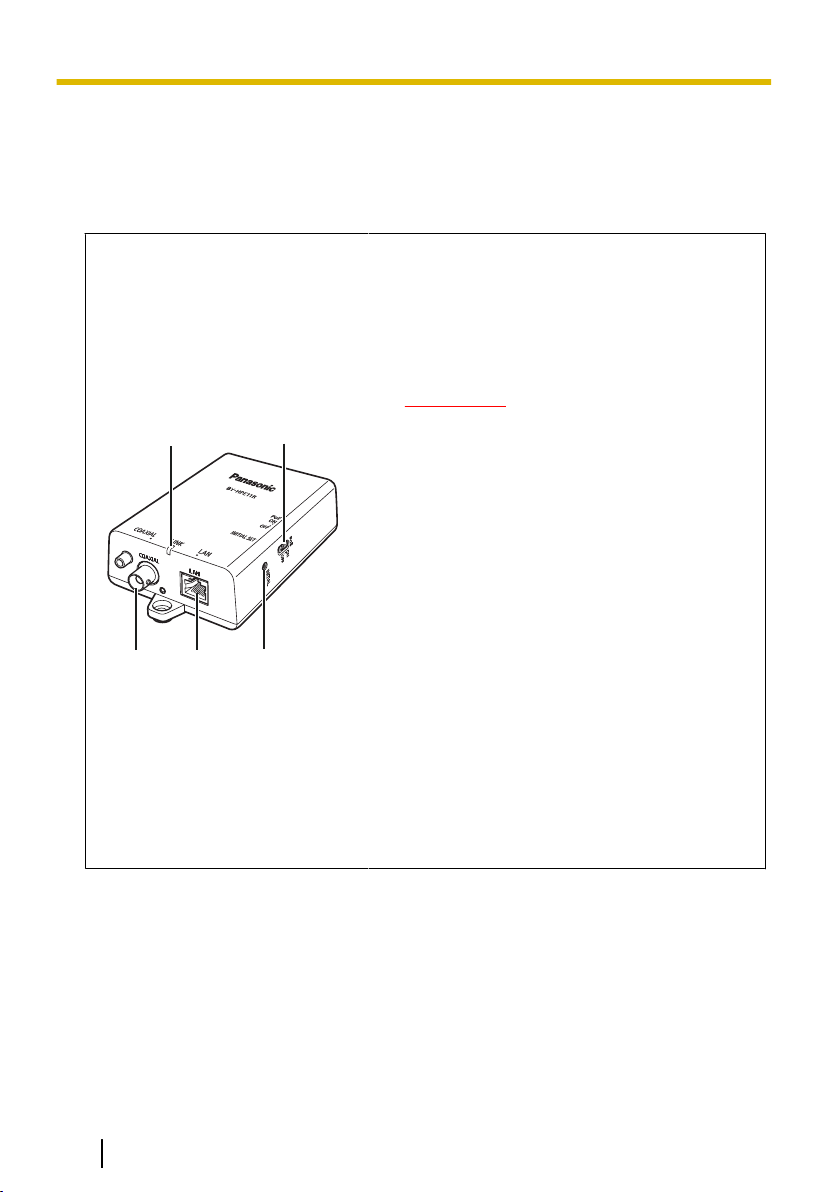
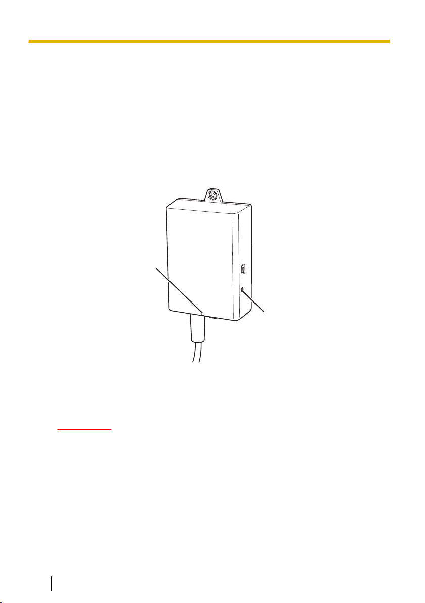
1.1 Camera Adaptor (BY-HPE11R)
Front view
A Indicator
Displays the status of the camera adaptor (see
page 7).
B PoE switch
Turns the PoE function ON/OFF. The default
setting is [ON].
IMPORTANT
• When using the camera adaptor’s PoE
function to supply power to a network
camera, set the PoE switch to [ON].
When not using the PoE function (when
powering the network camera with an
AC adaptor), set it to [OFF].
• The PoE function cannot be used for
connections over 500 m (1,640 feet 5
inches). Set the PoE switch to [OFF].
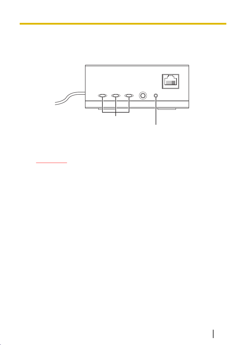
C
BNC connector
Connects the camera adaptor to the center
adaptor with a coaxial cable (see
3.2 Connections in the Installation Guide).
D Network connector
Connects the camera adaptor to a network
camera with a LAN cable (see
3.2 Connections in the Installation Guide).
E INITIAL SET button
Used to reset the camera adaptor to its factory
default settings (see page 8).
4 Operating Instructions
Page 5
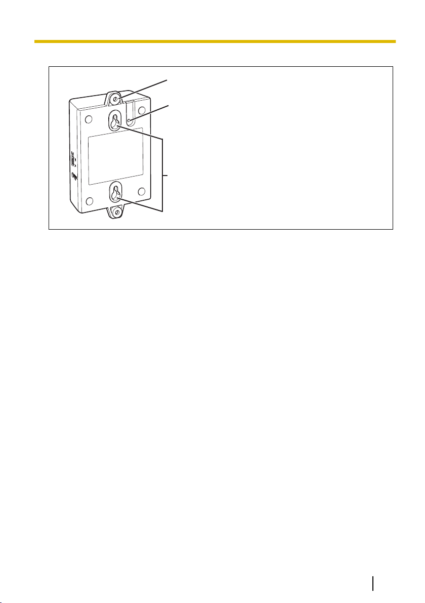
Rear view
A
B
C
1 Main Unit
A Used when attaching the camera adaptor to a
ceiling or wall with screws (see 2.1 Mounting
the Camera Adaptor in the Installation Guide).
B Used when attaching the safety wire (see
2.1 Mounting the Camera Adaptor in the
Installation Guide).
C Used when attaching the camera adaptor to
screws inserted into a wall.
Operating Instructions 5
Page 6
A
B
C
D
AB
1 Main Unit
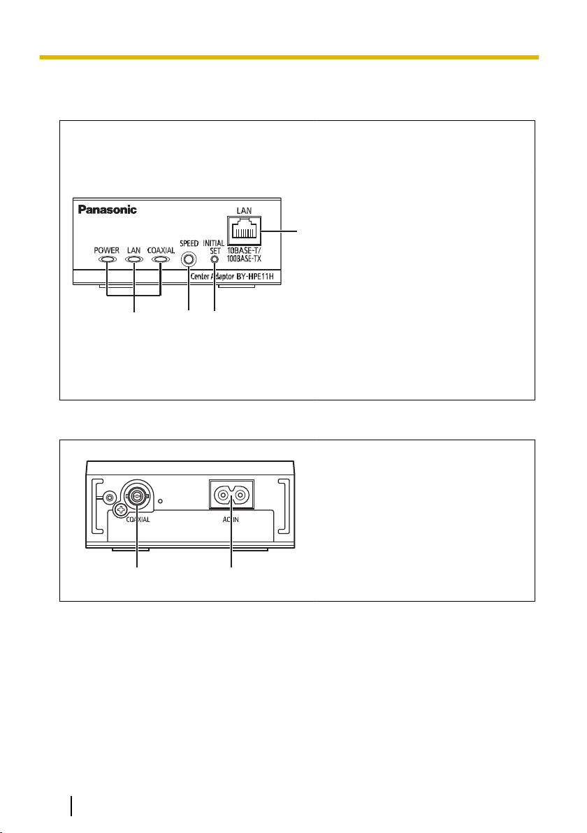
1.2 Center Adaptor (BY-HPE11H)
Front view
A Indicators
B SPEED button
C INITIAL SET button
D Network connector
Rear view
A
B AC IN
Displays the status of the center
adaptor (see page 7).
Used when measuring the speed
between adaptors (see
3.2 Connections in the Installation
Guide).
Used to reset the center adaptor to
its factory default settings (see
page 9).
Connects the center adaptor to a
network device with a LAN cable
(see 3.2 Connections in the
Installation Guide).
BNC connector
Connects the center adaptor to the
camera adaptor with a coaxial cable
(see 3.2 Connections in the
Installation Guide).
Connects the center adaptor to the
power outlet with the included AC
cord (see 3.2 Connections in the
Installation Guide).
6 Operating Instructions
Page 7
1 Main Unit
1.3 Understanding the Indicators
The light indicators change depending on the operating status of the camera and center
adaptors.
Camera adaptor
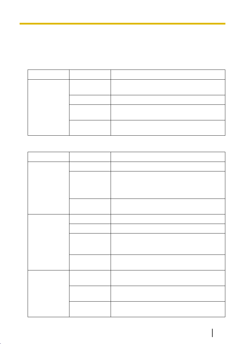
Indicator Light Status Meaning
Green (lit) The camera adaptor is connected to the center
adaptor.
Orange (lit) The camera adaptor is activating.
LINK
Center adaptor
Indicator Light Status Meaning
POWER
LAN
COAXIAL
Red (lit) The camera adaptor is malfunctioning. Contact an
authorized service center.
Off The center adaptor is not connected to the power
outlet, or the coaxial cable is not connected.
Green (lit) The center adaptor is active.
Green (flashing) The center adaptor may be connected to a device
other than the camera adaptor with the coaxial
cable. Check the connection with the camera
adaptor.
Off The center adaptor is not connected to the power
outlet.
Green (lit) A network device is connected.
Green (flashing) Sending/receiving data from a network device.
Orange (lit) A network device is not connected, or the
connected network device is not connected to the
power outlet.
Off The center adaptor is not connected to the power
outlet.
Green (lit) The camera adaptor is connected to the center
adaptor.
Red (lit) The center adaptor is malfunctioning. Contact an
authorized service center.
Off The center adaptor is not receiving power, or the
coaxial cable or camera adaptor is not connected.
Operating Instructions 7
Page 8
B
A
2 Resetting the Unit
2 Resetting the Unit
Reset the unit when reselling, disposing, or sending it for repairs.
2.1 Resetting Camera Adaptors
Reset the camera adaptor when it is connected to the center adaptor with a coaxial
cable, and the center adaptor is connected to the power outlet.
1. Press the camera adaptor’s INITIAL SET button (A) for about 3 seconds with a
pointed object.
• The indicator (B) will start flashing green.
2. The camera adaptor’s indicator (B) is lit green.
• Resetting is completed when the indicator is lit green after changing from flashing
green to flashing orange. However, depending on the condition of the connection,
the indicator may be lit green after alternating from flashing orange to lit orange.
IMPORTANT
• Do not disconnect the center adaptor’s AC cord, or the coaxial cable during
resetting or within 30 seconds after resetting, because the internal
information may not have completed resetting.
8 Operating Instructions
Page 9
A
B
2 Resetting the Unit
2.2 Resetting Center Adaptors
1. Press the center adaptor’s INITIAL SET button (A) for about 3 seconds with a
pointed object.
• All the indicators (B) will start flashing green.
2. All of the center adaptor’s indicators (B) are lit green.
• Resetting is completed when all the indicators are lit green after changing from
flashing green.
IMPORTANT
• Do not disconnect the center adaptor’s AC cord within 30 seconds after
resetting, because the internal information may not have completed resetting.
Operating Instructions 9
Page 10

3 Adaptor Maintenance Screen
3 Adaptor Maintenance Screen
The adaptor’s maintenance screen can be displayed on the web browser of a PC
connected to the network connector of an adaptor.
Settings such as the following can be performed in the maintenance screen.
– firmware version updates
– adaptor status confirmation
– IP address and password changes
IMPORTANT
• To display the maintenance screen of adaptors that have already been installed
or connected, directly connect the camera or center adaptor to a PC with a LAN
cable.
• In order to access the adaptor’s maintenance screen, you must temporarily
change the IP address assigned to your computer. Before you change the IP
address of your computer, note the IP address and network settings already
assigned to your computer.
• After you have finished using the maintenance screen, restore the
computer’s IP address and network settings to their original values.
• If you plan to update the adaptor’s firmware, download the latest version of the
adaptor’s firmware from the Panasonic support site
(http://panasonic.net/pss/security/products/coax/index.html) and save it on the
computer before you change the IP address of the computer.
10 Operating Instructions
Page 11

3 Adaptor Maintenance Screen
3.1 Accessing the Maintenance Screen
3.1.1 Temporarily Changing the Computer’s IP Address
Temporarily change the IP address assigned to your computer to access the adaptor’s
maintenance screen.
The procedure for changing the IP address differs depending on the operating system
used.
Windows® 7: Changing your computer’s IP address
In Microsoft® Windows 7, this procedure must be performed by either the
“Administrator” user, or a user assigned with administrator level privileges. Refer to the
help file supplied with the operating system for more information.
1. Click [Start]®[Control Panel]®[View network status and tasks].
2. Click [View your active networks]®[Local Area Connection].
3. Click [Properties] under [Local Area Connection Status].
4. Select [Internet Protocol Version 4 (TCP/IPv4)], then click [Properties].
Operating Instructions 11
Page 12

3 Adaptor Maintenance Screen
5. Select [Use the following IP address], then click [OK] after entering the IP address
(192.168.249.***) and Subnet mask (255.255.255.0). For the IP address,
***=1-254. However, 249 cannot be used.
6. Click [Close] to exit the [Local Area Connection Properties] screen.
IMPORTANT
• The procedure for changing the IP address may change depending on whether
the viewing method for Windows 7 is set to [Large icons] or [Small icons]. Refer
to the help file supplied with the operating system for more information.
12 Operating Instructions
Page 13

A
B
C
3 Adaptor Maintenance Screen
3.1.2 Accessing the Maintenance Screen
Follow the procedure below after you have changed the IP address of the computer.
1. Connect the adaptor (A: camera adaptor or center adaptor) and computer (C) using
a LAN cable (B). When accessing the camera adaptor, make sure it is connected
to the center adaptor with a coaxial cable, and that the center adaptor is connected
to the power outlet.
IMPORTANT
• To display the maintenance screen of adaptors that have already been
installed or connected, directly connect each adaptor to a PC with a LAN
cable.
2. Start the computer’s web browser.
• See page 16 for information on web browsers.
3. Enter http://192.168.249.249/ in the web browser’s address bar.
4. Enter the user name and password.
– Default user name: BY-HPE11
– Default password: 999999
• The screen shown here depicts the screen shown when using Windows 7.
Operating Instructions 13
Page 14

3 Adaptor Maintenance Screen
5. Click [OK].
• The maintenance screen is displayed.
IMPORTANT
• The screen shown here depicts the screen shown when accessing a center
adaptor. The screen displayed for the center adaptor and camera adaptor is
different.
• After you have finished using the maintenance screen, restore the
computer’s IP address and network settings to their original values.
• Only a PC connected to the adaptor’s network connector can display the
maintenance screen and perform firmware updates, etc.
• The maintenance screen is displayed in English.
14 Operating Instructions
Page 15

3.1.3 Maintenance Screen Overview
AB
C
D
E
FG
Model name
Name of current screen
Click to jump to the corresponding page
Click to restart the adaptor
Click to view the copyright information
Contents of the current screen
Click to update the displayed information
3 Adaptor Maintenance Screen
IMPORTANT
• The screen shown here depicts the screen shown when accessing a center
adaptor. The screen displayed for the center adaptor and camera adaptor is
different.
• When consecutively connecting adaptors to the computer to access their
maintenance screens, because the information (ARP table) of the previously
connected adaptor is retained, the maintenance screen may not be able to be
opened. Therefore, we recommend restarting the computer before connecting it
to another adaptor and accessing its maintenance screen.
You may reset the computer’s ARP table if you do not want to restart the
computer. Refer to the help file or operating instructions supplied with the
operating system for more information.
Resetting the ARP table when using Windows 7
1. Display the command prompt by clicking [Start]®[All
Programs]®[Accessories]®[Command Prompt].
2. Enter arp -d, then press [Enter].
Operating Instructions 15
Page 16

3 Adaptor Maintenance Screen
3.1.4 System Requirements
Operating System Web Browser
Microsoft® Windows® 7 Internet Explorer® (version 8.0 or later)
Microsoft® Windows Vista
Microsoft® Windows® XP Internet Explorer® (version 6.0 or later)
®
Internet Explorer® (version 7.0 or later)
16 Operating Instructions
Page 17

3 Adaptor Maintenance Screen
3.2 Using the Maintenance Screen
3.2.1 Updating the Adaptor’s Firmware
Make sure you download the latest version of the adaptor’s firmware from the Panasonic
support site (http://panasonic.net/pss/security/products/coax/index.html) and save it to
the computer before changing the computer's IP address and accessing the
maintenance screen.
1. Access the maintenance screen of the adaptor.
2. Click [Update Firmware].
3. Click [Browse...], select the firmware file, then click [Open].
4. Click [Start].
5. Click [OK] when prompted.
• The firmware will be updated, and then the adaptor will automatically restart. After
restarting, the updated firmware is used.
IMPORTANT
• After you have finished using the maintenance screen, restore the computer’s IP
address and network settings to their original values.
• Do not disconnect the center adaptor from the power outlet until the update is
completed.
• After you have updated the firmware, confirm the adaptor’s firmware version on
the [Status] screen. (See page 18)
• Update the firmware for both the camera adaptor and center adaptor.
Operating Instructions 17
Page 18

3 Adaptor Maintenance Screen
3.2.2 Confirming the Adaptor’s Status
You can confirm the information in the table below, such as the firmware version and
MAC address of the adaptor, on the [Status] screen.
1. Access the maintenance screen of the adaptor.
2. Click [Status].
IMPORTANT
• The screen shown here depicts the screen shown when accessing a center
adaptor. The screen displayed for the center adaptor and camera adaptor is
different. [Link Status] and [MAC Address of Master] are not displayed on the
camera adaptor’s screen.
Items Description
Boot Version Displays the adaptor’s boot version.
Firmware Version Displays the adaptor’s firmware version.
Operation Mode Displays the adaptor type (camera adaptor or center adaptor).
Camera adaptors are displayed as [Master], and center adaptors
are displayed as [Terminal].
MAC Address of this
equipment
Another Master Indicates whether other camera adaptors exist on the network.
Link Status (only
displayed for the
center adaptor)
Displays the MAC address of the connected adaptor.
If other camera adaptors exist on the network, [Detected] is
displayed, if they do not exist, [Not Detected] is displayed.
Communication performance may be affected if other camera
adaptors are detected.
Displays the status of the connection between the center and
camera adaptor. [Connected] is displayed when there is a
connection, and [Disconnected] is displayed when there is no
connection.
18 Operating Instructions
Page 19

3 Adaptor Maintenance Screen
Items Description
MAC Address of
Master (only
displayed for the
center adaptor)
PoE: Ethernet Link Displays the status of the connection between the camera adaptor
PoE: PoE Switch Displays the status of the camera adaptor’s PoE switch (ON/OFF).
PoE: PoE Power
Supply
Displays the MAC address of the connected camera adaptor. If no
camera adaptor is connected, [Unregistered] is displayed.
and network device.
[Link-up] is displayed if there is a connection, and [Link-down] is
displayed if there is no connection.
• When viewing the center adaptor’s maintenance screen,
information from the camera adaptor is obtained and displayed.
If the information cannot be obtained, [Unknown] is displayed.
• When viewing the center adaptor’s maintenance screen,
information from the camera adaptor is obtained and displayed.
If the information cannot be obtained, [Unknown] is displayed.
Displays whether the camera adaptor’s PoE function is able to
supply power to connected devices or not. [Enable] is displayed if
the camera adaptor is able to supply power, and [Disable] is
displayed if it is not.
• When viewing the center adaptor’s maintenance screen,
information from the camera adaptor is obtained and displayed.
If the information cannot be obtained, [Unknown] is displayed.
IMPORTANT
• After you have finished using the maintenance screen, restore the computer’s IP
address and network settings to their original values.
Operating Instructions 19
Page 20

3 Adaptor Maintenance Screen
3.2.3 Changing Adaptor Settings
The IP address and password for accessing the maintenance screen can be changed.
Changing the adaptor’s IP address
You may change the adaptor’s IP address and subnet mask if necessary.
Change the IP address in cases such as when the adaptor is using the same IP address
as another network device, or if you want to match the address used in the network.
1. Access the maintenance screen of the adaptor.
2. Click [Option].
3. Enter the desired IP address.
4. Enter the subnet mask if necessary.
5. Click [Set], then click [OK] when prompted.
6. Click [Restart].
• The adaptor will restart, and the new settings will take effect. The new IP address
must be entered in the web browser’s address bar in order to access the
adaptor’s maintenance screen again.
IMPORTANT
• After you have finished using the maintenance screen, restore the computer’s IP
address and network settings to their original values.
• Match the IP address and subnet mask settings to those used in your network.
• The screen shown here depicts the screen shown when accessing a camera
adaptor. The screen displayed for the center adaptor and camera adaptor is
different.
20 Operating Instructions
Page 21

3 Adaptor Maintenance Screen
Changing the adaptor’s password
You may change the adaptor’s password if necessary. The password is required to
access the maintenance screen.
1. Access the maintenance screen of the adaptor.
2. Click [Option], then click the [Account] tab.
3. Enter the desired password within 6-12 characters (only A-Z, a-z, and 0-9 can be
used).
• Passwords are case-sensitive.
• [Space], ["], ['], [&], [<], and [>] cannot be entered.
4. Click [Set], then click [OK] when prompted.
5. Click [Restart].
• The adaptor will restart, and the new settings will take effect. The new password
must be entered in order to access the adaptor’s maintenance screen again.
IMPORTANT
• After you have finished using the maintenance screen, restore the computer’s IP
address and network settings to their original values.
• To increase security, we recommend changing the adaptor’s password.
• Do not forget the password. If the password is forgotten, you can reset the
password to the default value (999999) by resetting the adaptor (see page 8). If
the adaptor is reset, all registration information is erased.
• Do not disclose the password, you are responsible for managing your password.
• The user name cannot be changed.
• The screen shown here depicts the screen shown when accessing a camera
adaptor. The screen displayed for the center adaptor and camera adaptor is
different.
Operating Instructions 21
Page 22

3 Adaptor Maintenance Screen
Viewing the center adaptor’s MAC address (only from the camera adaptor)
You can access the camera adaptor’s maintenance screen and view the MAC address
of the center adaptor.
1. Access the maintenance screen of the camera adaptor.
2. Click [Option], then click the [Terminal List/Delete] tab.
• The center adaptor’s MAC address is displayed.
• The [Delete] button, [Cancel] button, and check box cannot be used.
IMPORTANT
• After you have finished using the maintenance screen, restore the computer’s IP
address and network settings to their original values.
• The MAC address of the center adaptor is written on the underside of the center
adaptor.
22 Operating Instructions
Page 23

4 Troubleshooting
4 Troubleshooting
Before sending the unit in for repairs, check if the problem can be resolved by following
the troubleshooting steps.
If the problem cannot be solved by the steps in the troubleshooting, contact an
authorized service center.
4.1 Indicator Display Issues
Problem Cause and Remedy
All the indicators are
not lit.
Only the camera
adaptor’s indicator is
not lit.
The camera adaptor’s
LINK indicator is lit red.
The center adaptor’s
POWER indicator is
flashing green.
The center adaptor’s
LAN indicator is lit
orange.
• The center adaptor may not be receiving power.
→ Confirm that the AC cord is connected to the power outlet
and the AC IN of the center adaptor (see
3.2 Connections in the Installation Guide).
• The coaxial cable is not connected.
→ Connect the coaxial cable.
→ Confirm that the coaxial cable is not over 2 km (6,561
feet 8 inches) in length and is connected properly (see
3.2 Connections in the Installation Guide).
→ Confirm that there are no connection problems such as
damage or breaks in the cable.
• Data cannot be sent because the camera adaptor may be
malfunctioning.
→ Contact an authorized service center.
• The center adaptor may be connected to a device other than
the camera adaptor.
→ Check the connection with the camera adaptor (see
3.2 Connections in the Installation Guide).
• A network device is not connected to the network connector.
→ Connect a network device to the network connector with
a LAN cable (see 3.2 Connections in the Installation
Guide).
• The network device connected to the network connector may
not be receiving power.
→ Connect the network device to a power outlet (see
3.2 Connections in the Installation Guide).
• A network device is not connected to the network connector
with a LAN cable.
→ Confirm that the LAN cable is connected properly (see
3.2 Connections in the Installation Guide) and that there
are no connection problems such as damage or breaks
in the cable.
Operating Instructions 23
Page 24

4 Troubleshooting
Problem Cause and Remedy
The center adaptor’s
COAXIAL indicator is
not lit.
The center adaptor’s
COAXIAL indicator is lit
red.
• The center adaptor is not receiving power.
→ Confirm that the AC cord is connected to the power outlet
and AC IN of the center adaptor (see 3.2 Connections
in the Installation Guide).
• The coaxial cable is not connected.
→ Confirm that the coaxial is not over 2 km (6,561 feet 8
inches) in length and is connected properly (see
3.2 Connections in the Installation Guide).
→ Confirm that there are no connection problems such as
damage or breaks in the cable.
• The camera adaptor is not connected.
→ Connect the center and camera adaptors with a coaxial
cable (see 3.2 Connections in the Installation Guide).
• Data cannot be sent because the center adaptor may be
malfunctioning.
→ Contact an authorized service center.
4.2 Communication Speed Issues
Problem Cause and Remedy
When testing the
communication speed,
all the indicators are off,
or only 1 or 2 of the
indicators are lit.
• The communications speed may be affected due to issues
with the installation environment.
→ This is not a malfunction. Confirm that there are no
problems with using the camera or displaying images.
→ Confirm that the coaxial cable is of a suitable type and
length, and that there are no devices near the unit that
may cause strong interference.
24 Operating Instructions
Page 25

4.3 PoE Issues
Problem Cause and Remedy
Network cameras
connected to the
camera adaptor do not
function.
The status of the [PoE:
PoE Power Supply] on
the maintenance
screen is set to
[Disable] and the PoE
function cannot supply
power.
4 Troubleshooting
• The connection distance may be too long.
→ The PoE function cannot supply power to devices
connected at distances over 500 m (1,640 feet 5 inches).
→ Confirm that the connected LAN cable is a PoE standard
cable (see 3.1 Connection Example in the Installation
Guide), that the LAN cable is connected properly, and
that there are no connection problems such as damage
or breaks in the cable.
• If the LAN cable was quickly disconnected and then
reconnected, the PoE function may not be able to supply
power.
→ Disconnect the LAN cable and then reconnect after
waiting for more than 2 seconds.
• The status of the [PoE: Ethernet Link] on the maintenance
screen is set to [Link-down].
→ Confirm that the camera adaptor, network camera and
other network devices are connected properly, that there
are no connection problems such as damage or breaks
in the cables, and that network devices are connected to
the power outlet (see 3.2 Connections in the Installation
Guide).
• The status of the [PoE: PoE Switch] on the maintenance
screen is set to [OFF].
→ Turn the PoE switch on the camera adaptor to [ON] (see
page 4).
• Power cannot be supplied normally from the center adaptor
to the camera adaptor.
→ The PoE function cannot supply power to devices
connected with coaxial cable at distances over 500 m
(1,640 feet 5 inches) (see 3.2 Connections in the
Installation Guide).
→ The PoE function may not be able to supply power if the
line resistance of the coaxial cable is of a high value (see
3.2 Connections in the Installation Guide).
4.4 Other Issues
Problem Cause and Remedy
The unit is warm. • This is normal. (The unit may seem slightly warmer in
summer than compared to winter.)
→ If the unit gets extremely hot, disconnect the power plug
and contact an authorized service center.
Operating Instructions 25
Page 26

5 Specifications
5 Specifications
Center Adaptor (BY-HPE11H)
Items Specifications
Operating Environment Temperature: 0 °C (32 °F) to 50 °C (122 °F)
Humidity: 20 %–85 % (no condensation)
Interfaces
Dimensions (W´H´D) About 105 mm ´ 44 mm ´ 210 mm
Mass (Weight) About 570 g (1.26 lb)
Power Supply AC 100–240 V 50/60 Hz 0.6 A
Power Consumption Maximum about 28 W (including the power consumption of the
Coaxial Cable Power
Supply Capability
Camera Adaptor (BY-HPE11R)
10Base-T/100Base-TX ´ 1
AUTO MDI/MDI-X AC inlet
BNC connector
(4 1/8 inches ´ 1 3/4 inches ´ 8 1/4 inches) (main body only)
camera adaptor)
Maximum 22 W
Items Specifications
Operating Environment Temperature: -10 °C (14 °F) to 50 °C (122 °F)
Humidity: 20 %–90 % (no condensation)
Interfaces
Dimensions (W´H´D) About 80 mm ´ 115 mm ´ 35 mm
Mass (Weight) About 165 g (0.36 lb)
Power Supply Original power system (DC 55 V from the center adaptor via the
Power Consumption Included in the center adaptor’s power consumption
PoE Power Supply
Capability
26 Operating Instructions
10Base-T/100Base-TX ´ 1
AUTO MDI/MDI-X (PoE compatible)
BNC connector
(3 1/8 inches ´ 4 1/2 inches ´ 1 3/8 inches) (main unit only)
coaxial cable)
Maximum 15.4 W
(see page 28 for more information)
Page 27

5 Specifications
Coaxial Interface
Items Specifications
Standard Panasonic original system
Frequency Range 2 MHz–28 MHz
Data Transfer Mode Wavelet OFDM
Access Method CSMA/CA
Error Correction Reed-Solomon Code + Convolutional Code (Viterbi decoding)
LAN Interface
Items Specifications
Standard IEEE802.3/IEEE802.3u
(10Base-T/100Base-TX)
MDI/MDI-X Cross/Straight cable automatic recognition
Transmission Rate 10 Mbps/100 Mbps (Auto-Sensing)
Number of Ports 1 (RJ-45 connector)
Protocol TCP/IP/UDP
Access Method CSMA/CD
Connection Specifications
Items Specifications
Number of adaptors
that can be
communicated with
Connectable Devices Center adaptor: devices equipped with 10Base-T/100Base-TX
Number of devices that
can be connected
1 camera adaptor can be connected via coaxial cable for each
center adaptor
interfaces
Camera adaptor: Panasonic network cameras (see
http://panasonic.net/pss/security/products/coax/index.html for
more information)
A maximum of 256 center adaptors or camera adaptors can be
connected in 1 segment
Operating Instructions 27
Page 28

5 Specifications
Maintenance Screen Specifications
Items Specifications
Compatible Operating
Windows XP, Windows Vista, Windows 7
Systems
Web Browser Internet Explorer 6.0, 7.0, 8.0 or later
Performance Specifications
Items Specifications
Transmission Speed
(UDP)
Transmission Speed
(TCP*2)
Maximum
Transmission Distance
*1
This value is for transmissions between the BY-HPE11H and BY-HPE11R. The transmission speed when
using an RG-6/U coaxial cable may very depending on factors such as the coaxial cable condition and
network environment. The values shown here measured in environments not affected by cable or network
environment conditions.
*2
Measured using Linux® FTP.
*1
45 Mbps or higher (when using an RG-6/U coaxial cable at
distances under 2 km [6,561 feet 8 inches])
*1
35 Mbps or higher (when using an RG-6/U coaxial cable at
distances under 2 km [6,561 feet 8 inches])
Without PoE function: 2 km (6,561 feet 8 inches)
With PoE function: 500 m (1,640 feet 5 inches) (when using a
Panasonic network camera) / 300 m (984 feet 3 inches) (when
using a Class0 standard network camera)
Maximum Transmission Distance / PoE Power Supply (when using RG-6/U
coaxial cable) Specifications
Maximum
Transmission
Distance
Power
Supplied by
300 m
(984 feet 3
inches)
*1
15.4 W
PoE
*1
When connecting an IEEE802.3af (Alternative B, class0) network camera to the camera adaptor
(BY-HPE11R).
*2
When connecting a Panasonic network camera (see
http://panasonic.net/pss/security/products/coax/index.html for more information) to the camera adaptor
(BY-HPE11R).
*3
Turn the PoE switch [OFF] in this situation.
28 Operating Instructions
500 m
(1,640 feet 5
inches)
*2
12.0 W
1,000 m
(3,280 feet
10 inches)
1,500 m
(4,921 feet 3
inches)
Cannot supply power with PoE
2,000 m
(6,561 feet 8
inches)
*3
Page 29

5 Specifications
RG-6/U coaxial cable
In this document coaxial cables with the following specifications are referred to as
RG-6/U coaxial cables.
Coaxial Cable
Type
RG-6/U
DC R/300 m (984 feet
3 inches) of Inner
Conductor
Less than 12 W
Maximum Cable
Length (for PoE
connections)
500 m (1,640 feet 5
inches)
Maximum Cable
Length (for non-PoE
connections)
2,000 m (6,561 feet 8
inches)
Accessories
Rack Mount Connecting Fitting: BY-HCA10A
Operating Instructions 29
Page 30

www.panasonic.com/business/
For customer support, call 1.800.528.6747
Three Panasonic Way, Secaucus, New Jersey 07094 U.S.A.
5770 Ambler Drive, Mississauga, Ontario, L4W 2T3 Canada
(905)624-5010
www.panasonic.ca
© Panasonic System Networks Co., Ltd. 2010
PNQX3083ZA KK1110MJ0
 Loading...