

Page 1
Operating Instructions
Network Camera
Model No. BL-C30A
Please read this manual before using and save this manual for future reference.
Panasonic Network Camera Website: http://www.panasonic.com/netcam
for customers in the USA or Puerto Rico
Page 2

Operating Instructions
Main Features
Wireless Communication
Network Camera corresponds to the wireless system based on IEEE 802.11b/g.
Wireless installation will play an increasing role in flexible mounting.
Communication via Ethernet
security on the wireless network.
Various remote monitoring features
• Pyroelectric infrared sensor*1 detects temperature differences caused by a
human body or animals.
• Detection can let camera transfer images by E-mail or FTP
• Color night view m ode (auto-adjusted) enables the camera to dis pl ay images
even in 1 lx illuminance*3.
Monitoring from PC or mobile phone
• The camera images can be monitored over the Internet.
• Pan/tilt operation can move the lens horizontally from -50 ° to +50 ° and
vertically from -40 ° to +10 °.
Privacy mode
• Privacy mode hides the lens into the unit to protect privacy.
• Pressing the privacy button on the front of the camera switches privacy mode
on or off with a single touch.
®
cable is also available. Encryption establishes the
*2
.
Privacy Monitoring Purpose
Privacy mode On Disabled Protecting privacy
Monitoring Off Enabled Remote monitoring
*1
The sensor uses pyroelectric effect. Due to the effects of environment temperature, direct
sunlight or air conditioner, it may detect the temperature differences by mistake, or the
detection range may be shortened.
*2
It may take some time to transfer images depending on the network condition.
*3
1 lx is the brightness about 2.5 m (8.2 feet) away from auxiliary fluoresce nt light. Color night
view mode slows down the frame rate, and images may blur when viewing a mo ving object or
using the pan/tilt operation.
2
Page 3

Operating Instructions
Easy installation using UPnP (Universal Plug and Play)
When connecting the ca mera with a UPnP enabled router, the camera
automatically configures its networ k settings.
* Some UPnP enabl ed routers cannot configure the camera automatically. In
this case, the router needs to be configured manually. Ask the router
manufacturer how to configure it. See Panasonic Network Camera support
website at
http://panasonic.co.jp/pcc/products/en/netwkcam/ for more information.
Supporting Viewnetcam.com service
Viewnetcam.com service allows you to access the camera over the Internet with
your favorite domain name (e.g. bob.viewnetcam.com) instead of a global IP
address.
* Viewnetcam .com service is the service for Panasonic Network Camera. See
Viewnetcam.com website (http://www.viewnetcam.com) for more
information.
Multi-Language Display
Top page, Single Camera and Multi-Camera page can be displayed in English,
French, German, Ita lian, Spanish, Rus sian, Simplifie d Chinese or J apanese. If y ou
select English or Japanese, all pages can be changed. But if you select other
language, the Setup, Maintenance and Support pages are displayed only in
English.
[For assistance, please call: 1-800-272-7033] 3
Page 4

Operating Instructions
System Requirements for your PC
Your PC (Personal Computer) and network must meet the following technical
specifications for the camera to work properly.
Item Description
®
Operating
System
Microsoft
Microsoft
CPU Pentium
Windows® XP, Microsoft® Windows® 2000
®
Windows® Me, Microsoft® Windows® 98SE
®
III (500 MHz or greater is recommended.)
Protocol TCP/IP protocol (HTTP, TCP, UDP, IP, DNS, ARP, ICMP)
Interface 10/100 Mbps network interface installed
Web Browser Internet Explorer 6.0 or later (Not included on the Setu p CD-
ROM)
Note
See Panasonic Network Camera support website at
http://panasonic.co.jp/pcc/products/en/netwkcam/ for the latest
information about web browser.
Trademarks
• Adobe and Acrobat are either registered trademarks or trademarks of Adobe
Systems Incorporated in the United States and/or other countries.
• Ethernet is either a registe red tradem ark or a tradem ark of Xero x Corporation
in the United States and/or other countries.
• Microsoft, Windows, Hotmail and ActiveX are either registered trademarks or
trademarks of Microsoft Corporation in the United States and/or other
countries.
• Pentium is a trademark or registered trademark of Intel Corporation or its
subsidiaries in the United States and other countries.
• Screen shots reprinted with permission from Microsoft Corporation.
• All other trademarks identified herein are the property of their respective
owners.
Abbreviations
• UPnP is the abbreviation for Universal Plug and Play.
• "Network Camera" is called "Camera" in this Operating Instructions.
4
Page 5

Operating Instructions
IMPORTANT SAFETY INSTRUCTIONS
When using this unit , basic saf ety precautions should alw ays be f ollow ed to reduce
the risk of fire, electric sh ock, or personal injury.
1. Read and understand all instructions.
2. Keep these instructions.
3. Heed all warnings.
4. Follow all instructions.
5. After taking away the dust on the lens, wipe the lens with a cotton bud.
6. Do not install near an y hea t source s suc h as radia tors , heat re gisters , s toves,
or other devices (including amplifiers) that produce heat.
7. Protect the AC adaptor cord from being walked on or pinched particularly at
plugs, convenience receptacles, and the point where they exit from the unit.
8. When you operate the camera, the power outlet should be near the camera
and easily accessible.
9. Do not touch the unit or the AC adaptor during lightning storms.
10.Unplug the unit when unused for long periods of time.
11.Refer all servicing to qualified service personnel. Servicing is required when
the unit has been damaged in an y wa y, such as the AC adaptor cord or plug is
damaged, the unit does not operate normally, or has been dropped.
12.The camera is intended for indoor use only. Prolonged exposure to direct
sunlight or halogen light may damage CMOS sensor.
User Name and Password Protection
The use of a unique User Name and secret P asswor d is an important tool that
will help limit unauthorized individuals from accessing the camera. If you
choose to disable this tool, and choose not to limit access by use of a User
Name and Password, this may result in access to the camera by
unauthorized individuals. (see page 46)
SAVE THESE INSTRUCTIONS
[For assistance, please call: 1-800-272-7033] 5
Page 6

Operating Instructions
Table of Contents
1 Camera Monitoring .......................................................8
1.1 Accessing the Camera................................................................... 8
1.2 Viewing Single Camera page.......................................................10
1.2.1 Image Auto Centering (Click to Center)...................................................13
1.2.2 Capturing a Still Image............................................................................14
1.2.3 Using Operation Bar..................... ...... ..... ................................................15
1.2.4 Setting Home Position/Sensor Position/Preset Button............................. 17
1.3 Viewing Multi-Camera page......................................................... 21
1.4 Viewing Buffered Image page......................................................23
1.4.1 Deleting Buffered Images........................................................................24
1.5 Viewing Still Images on Your Mobile Phone................................. 25
2 Various Camera Features...........................................27
2.1 Using Camera Features............................................................... 27
2.2 Connecting the Camera to Your Network.....................................30
2.3 Using Wireless LAN..................................................................... 34
2.4 Using UPnP (Universal Plug and Play)........................................ 37
2.5 Registering with the Viewnetcam.com service ............................38
2.6 Setting Date and Time .................................................................40
2.7 Changing Camera Settings.......................................................... 42
2.8 Changing Authentication Setting and Administrator User Name and
Password..................................................................................... 46
2.9 Logging in to the Camera.............................................................49
2.10 Creating, Modifying or Deleting General Users ........................... 50
2.11 Changing Initial Settings on the Single Camera page or the Multi-
Camera page ............................................................................... 52
2.12 Configuring Multiple Cameras......................................................55
2.13 Buffering or Transferring Images by Timer...................................57
2.14 Buffering or Transferring Images by Sensor................................. 64
2.15 Specifying Operation Time ..... ....... ....................................... ...... .. 74
2.16 Changing Indicator Display..........................................................76
2.17 Enabling Privacy Mode ................................................................77
6
Page 7

Operating Instructions
3 Camera Maintenance ..................................................78
3.1 Maintenance page .......................................................................78
3.1.1 Confirming the Status.............................................................................. 79
3.1.2 Confirming the Wireless Status............................................................... 79
3.1.3 Restarting the Camera............................................................................ 80
3.1.4 Updating the Camera Firmware.............................................................. 81
3.1.5 Creating Configuration File...................................................................... 84
3.1.6 Loading Settings from a Configuration File ............................................. 85
3.1.7 Resetting the Camera to Factory Default ................................................86
3.2 Suppor t pag e ............................................ ....... ...... ....... ...... ....... .. 87
3.2.1 Seeing Help page................................................. ..... .............................. 87
3.2.2 Seeing Wireless Help page....................... ..... ...... ..... .............................. 88
3.2.3 Seeing Product Information....................................... ...... ...... ..... ...... ....... 88
3.2.4 Seeing Support Information................................................... ..... ...... ...... .88
3.3 FACTORY DEFAULT RESET Button............................................89
3.4 Default Setting List.......................................................................90
3.5 Cleaning.......................................................................................98
3.5.1 Cleaning the Main Unit............................................................................ 98
3.5.2 Cleaning the Lens.................................................................................... 98
3.6 Setting an IP Address on Your PC ...............................................99
3.7 Using Setup Program.......................... ...... ....... ...... ....... .............100
3.8 Setting Your PC..........................................................................103
3.8.1 Setting the Proxy Server Settings on Web Browser ............................. 103
3.8.2 Setting UPnP to Display Camera Shortcut in My Network Places........106
3.8.3 Setting the Internet Temporary File Setting on Web Browser................ 106
3.9 ASCII Character T a ble ...............................................................107
3.10 File Size and Number of Buffered Images .................................108
3.11 Specifications.............................................................................109
Index..................................................................................111
[For assistance, please call: 1-800-272-7033] 7
Page 8

Operating Instructions
1 Camera Monitoring
1.1 Accessing the Camera
1. Start up the web browser on your PC.
2. Enter "http://IP Address (or URL):Port Number" on the address bar, and
press [Enter] on the keyboard.
E.g. http://192.168.0.253
(or http://XXXXX.viewnetcam.c om)
• When port number is 80 (default), you do not need to enter port number.
See page 32 fo r details abo ut port number , and page 11 in the Installation /
Troubleshooting.
• If the Internet access to the camera is desired, the port number will be
changed in the order from 50000 to 50050. It is changed because some
ISPs block port 80.
Note
When [Prohibiting unregistered users] is set on the Secu rity: Administrator
page, authentic ation window w ill be displa yed. Ente r the administr ator's or the
general user's user name and password, and the Top page is displayed.
8
Page 9

Operating Instructions
3. Click the following tabs to display each page.
A B C D E F
A To Single Camera page (page 10) B To Multi-Camera page (page 21)
C To Buffered Image page (page 23) D To Setup page (page 27)
E To Maintenance page (pag e 78) F To Support page (page 87)
GTo log in to the camera (page 49)
Note
When users other than an administra tor are acc es sing the came ra , [Setup]
and [Maintenance] tab will not be displayed. Additionally, When [Prohibiting
unregistered users] i s s et on the Sec urity: Ad mi nis trator page, [Login] tab will
not be displayed.
G
Select a language
to display.
[For assistance, please call: 1-800-272-7033] 9
Page 10

Operating Instructions
1.2 Viewing Single Camera page
1. Access the camera (see page 8).
• The Top page is displayed.
2. Click the [Single] tab at the top of the page.
• When Security Warning window is displayed, see page 11.
Capture Image
Button
(see page 14)
Click to Center
(see page 13)
Operation Bar
(see page 15)
Refresh Interval
(see page 15)
Camera Image
The banner is
displayed.
(see page 12)
3. Close the web browser.
Notes
• While viewing images under florescent lighting, the image may appear
noisy or experi ence fli c k er if th e inco rrect AC power setting was selec ted.
Select 60 Hz in the U.S. (see page 42).
• Refresh interval is [Motion ] by default. You can change it on the operation
bar (see page 15).
• Refresh interval may change depending on the network condition, PC
performance and what object you view.
• When displaying video (Motion JPEG), the camera allows up to 20
simultaneous accesses. When trying more than 20 accesses, the 21st
user will see a gray screen. (Maximum 20 accesses for a Buffered Image
page too.)
• If the video (Motion JPEG) displ ay is limited (see page 52), the video will
be changed to refreshing still images.
10
Page 11
Operating Instructions
• To reduce the data traffic, the video can be automatically changed to
refreshing still images (see page 52).
• To display the Si ngle Cam era pag e directl y, add it to the [ F av orites ] on the
web browser.
• Refresh interval may slow down depending on the network condition or
the number of accessing users.
• When viewing a dark imag e, Color N igh t Vie w mode automa tical ly sta rts.
The image will be brighter, but the refresh interval may slow down and
image quality may decrease.
• The image ma y stop ref reshing bec ause the w ireless comm unication can
be disconnected depending on the environment.
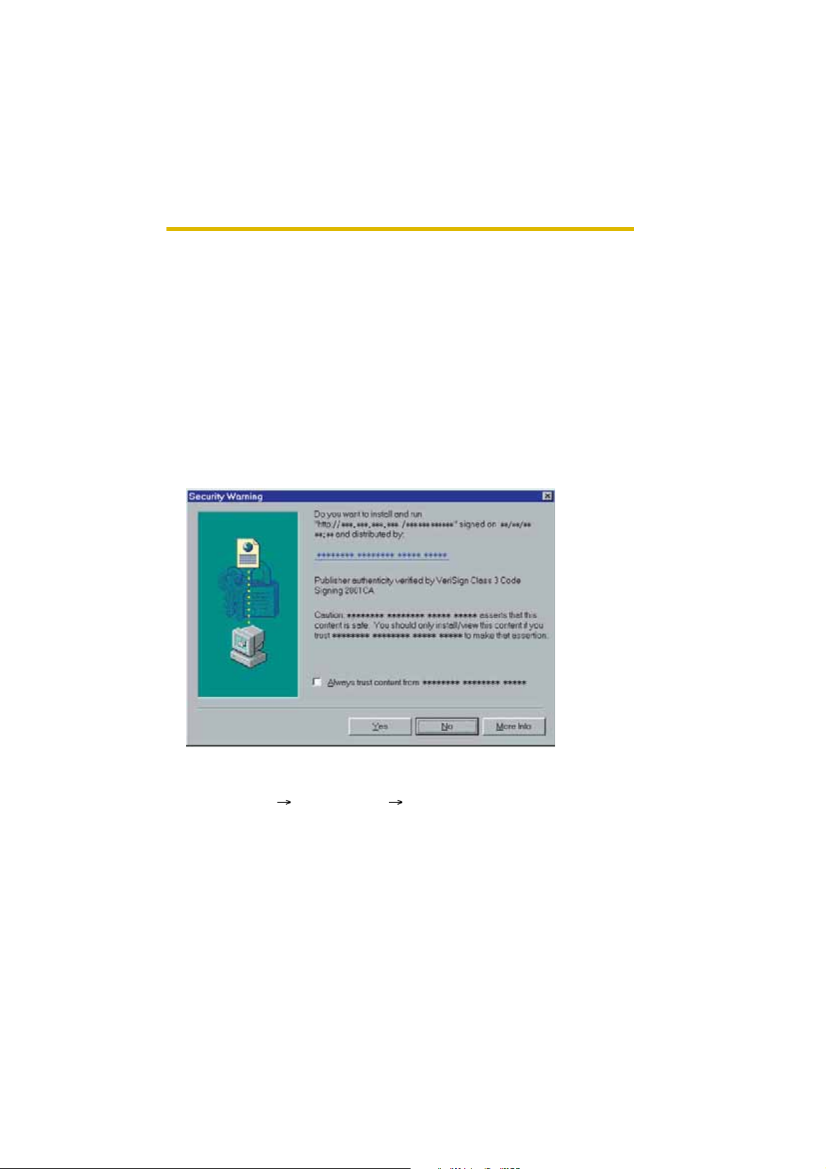
Security Warning window
To view a video (Motion JPEG), ActiveX® Controls must be installed. When trying
to display a video for the first time, Security Warning window will be displayed.
When using Windows XP or W indows 2000, log in as an administrator to install it.
If you cannot install ActiveX Controls or you cannot see the video in the
Internet Explorer
• Click [Tools] [Internet Options] [Security] tab and click [Custom level] on
the web browser.
(1) Check "Prompt" in "Download signed ActiveX Controls".
(2) Check "Enable" in "Run ActiveX Controls and plug-ins".
• ActiveX Controls can be installed from the file on the Setup CD-ROM.
(1) Restart the PC.
(2) Confirm that Internet Explorer is closed.
(3) Double-click "o cx\Ac tiveXInst.exe" on the Setup CD-ROM.
[For assistance, please call: 1-800-272-7033] 11
Page 12

Operating Instructions
Notes
• Video may not be displayed quickly. Wait for a while.
• If you use a proxy server, set the web browser not to access the proxy server
(see page 103).
• In some corporate net work environments a firewall may be used for secu rity
purposes. It is possible that this may prevent motion video from being
displayed. In this situation we suggest:
• Contact your network admini str a tor.
• Try using regularly refreshed images.
The Banner
When the camera accesses the Internet, the banner displays product information
about cameras or an nounc ement s abo ut the lates t firmware, etc. from Panasoni c.
Whether or not to display the banner can be set at Banner Display (see page 52).
Notes
• The banner is displayed when [Yes] is checked for Allow Access from the
Internet on the Automatic Setup page, or when [Enable] is checked for Auto
Port Forwarding on the UPnP page for the Connection Mode of Static or
DHCP.
• Even if [Yes] is checked for Allow Access from the Internet on the Automatic
Setup page, or [Enable] is chec ked f or Auto P ort Forward ing on the UPnP p age
for the Connectio n Mode of Static or DHCP, when the camera is not connected
to the Internet, is displayed.
12
Page 13
Operating Instructions
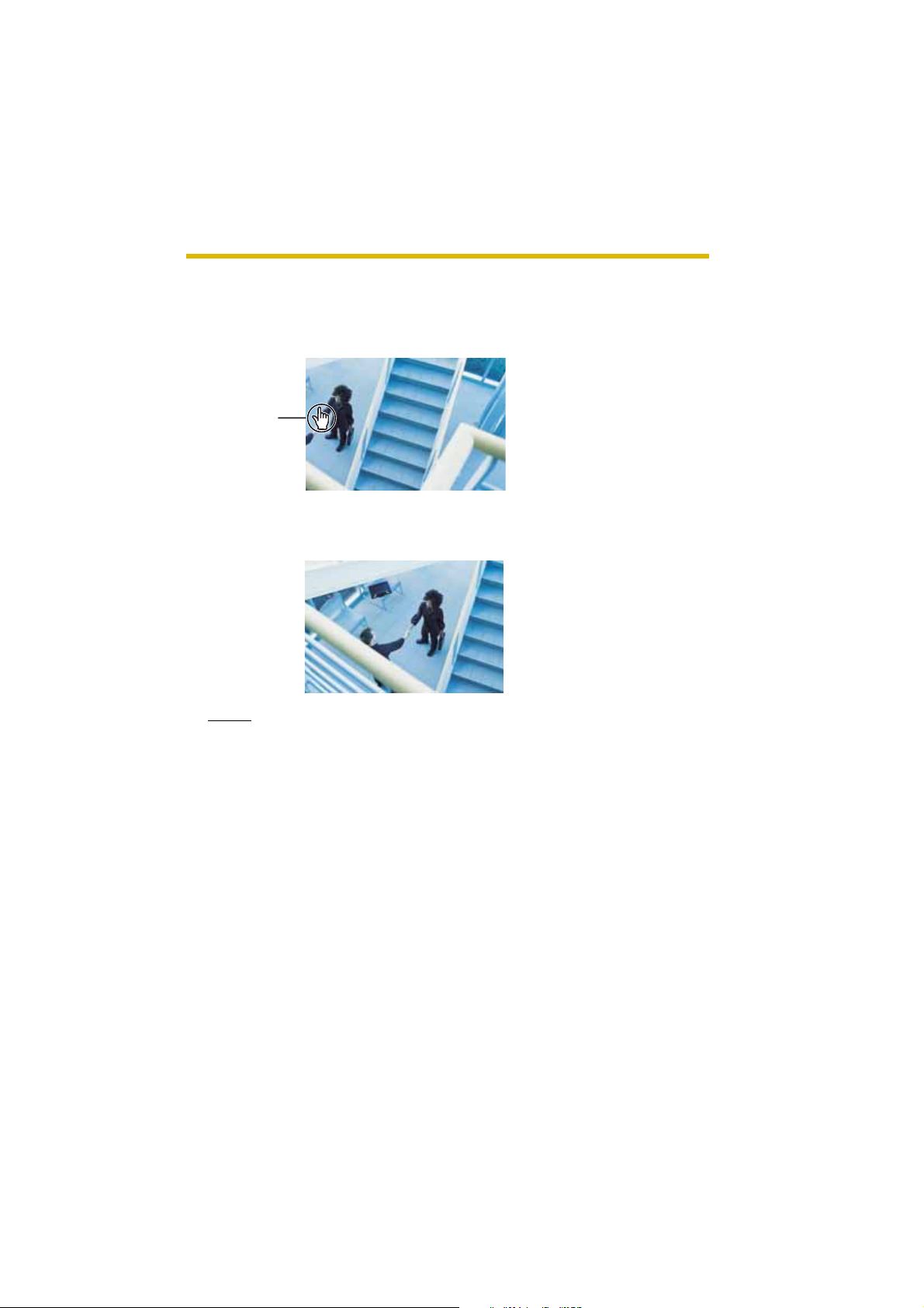
1.2.1 Image Auto Centering (Click to Center)
When you click a certain point on the camera image, the point is centered on the
image.
1. Move the cu rsor to the desired point.
Cursor
2. Click it.
• The clicked point is centered.
• See page 16 for the pan/tilt operation.
Notes
• When End Displa y appears on the oper ation bar , Clic k to Center does not
work beyond the pan/tilt end (see page 15).
• The clicked position may slightly miss the center depending on the lens
direction.
• If a user is restricted to level 1 or 2 on the General User page (see page
50), Click to Center does not work.
[For assistance, please call: 1-800-272-7033] 13
Page 14

Operating Instructions
1.2.2 Capturing a Still Image
A still image can be saved on your PC.
1. Operate pan/tilt and select a resolution to display an image.
2. Click the capture image button.
Capture Image Button
• The camera image opens in another window.
3. Right-click the image, and select [Save Picture As...].
14
• Save as dialog box is displayed.
4. Specify the location, and click [Save].
• Camera image is saved at that location.
5. Click [Close].
Page 15
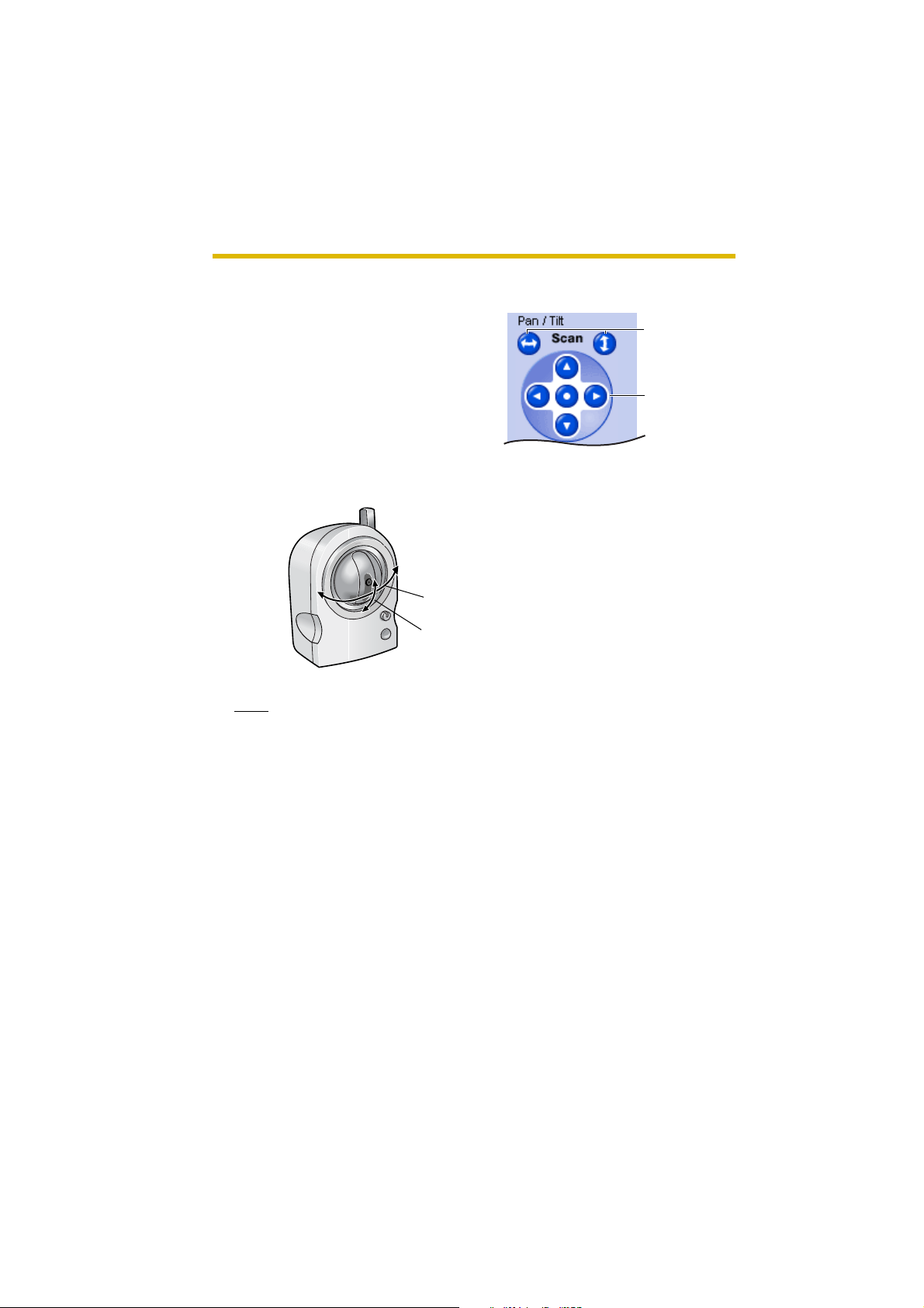
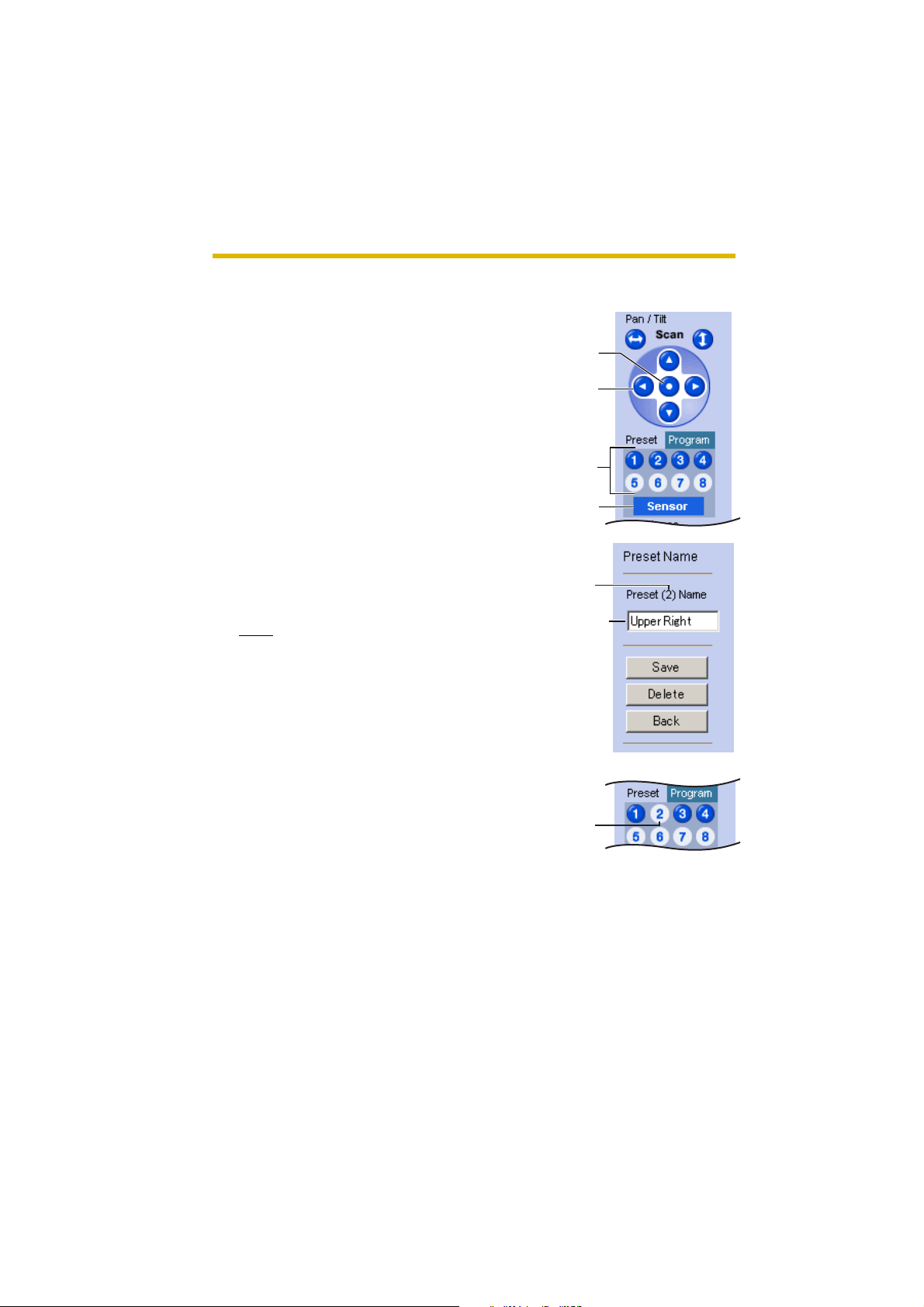
1.2.3 Using Operation Bar
Operating Instructions
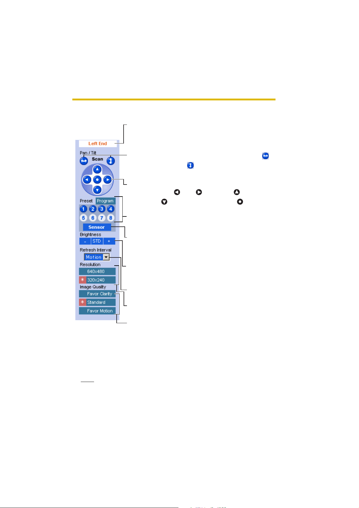
End Display
and Preset
Display:
Pan/Tilt
Scan:
Pan/Tilt/
Home
Position:
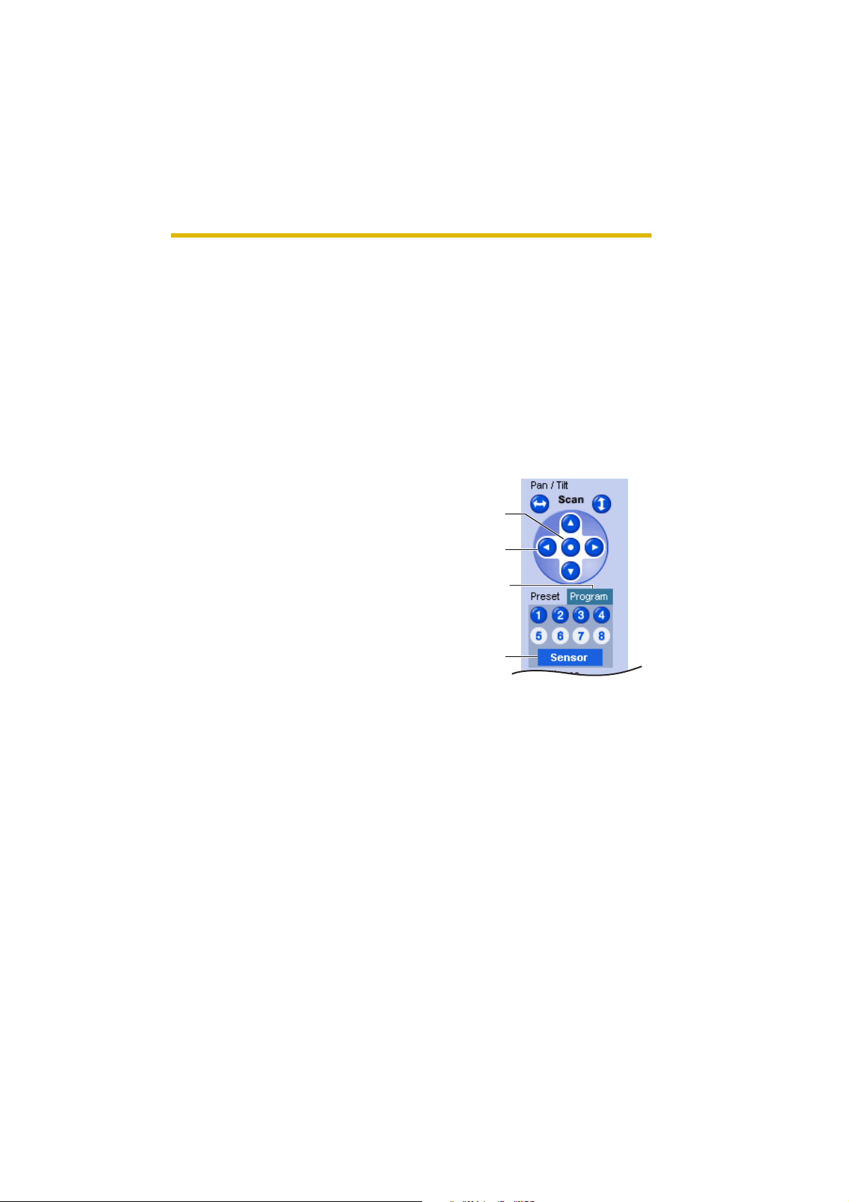
Preset
Button:
Sensor
Position:
Brightness: Changes brightness in ni ne steps including
Refresh
Interval:
When the pan/tilt has reached the end (Left
End, Right End, Up End and Down End), End
Display app ears. When clic king a preset bu tton,
the preset name appears.
Moves the lens throughout the horizontal ( )
or vertical ( ) range, and returns to the original
position.
Controls lens direction.
Pan ( : Left, : Right), Tilt ( : Up,
: Down) and Home Position ( : Center)
Applies the camera direction to a preset
position. You can preset 8 positions (see page
17—page 20).
When the sensor detects a temperature
difference, the camera can be set up to turn to
this position. On ly an adminis trator can op erate
it (see page 17).
[STD] (Standard). Clic king [-] or [+] cha nges the
image bri ghtness.
Sets a refresh interval. (Motion—60-second
interval)
Resolution: Selects [640 x 480] or [320 x 240] (default)
pixels.
Image
Quality:
Selects the image quality.
• [Fa vor Clarity] optim izes the image for good
clarity.
• [Standard] keeps the standard quality.
(default)
• [Favor Motion] optimizes the image for
motion display.
Note
When the camera image is not displayed correctly, click [Refresh] at the tool
bar on the web browser. The image will be refreshed.
[For assistance, please call: 1-800-272-7033] 15
Page 16
Operating Instructions
Pan/Tilt Operation
Pan/tilt scan buttons automatically move the
lens horizontally from -50 ° to +50 ° and
vertically from -40 ° to +10 ° and return the
lens to the original position. Each pan/tilt
arrow moves the lens Up , Down, Right or Left,
and the home position button moves it to the
home position.
Pan/Tilt Range
Pan: -50
Tilt: -40
˚ to +50 ˚
˚ to +10 ˚
Note
Do not apply pressure to the pan/tilt portion of the camera. Any forced
movement can damage the internal mechanism.
Pan/Tilt
Scan
Pan/Tilt
16
Page 17
Operating Instructions
1.2.4 Setting Home Position/Sensor Position/Preset
Button
The home position, sen sor position and 8 preset bu ttons can be re gistered. Prese t
buttons (1—4) are registered 1: Upper Left, 2: Upper Right, 3: Lower Left and 4:
Lower Right. These buttons can be changed (see page 20).
• Registered buttons are shown in blue.
• Unregistered buttons are shown in white.
When clicking e ach button, the image switc hes to the home/s ensor/preset position.
When restarted, the camera takes a home position. If the Lens Position When
T riggere d setting is s et (see page 65 ), the camer a takes a sensor posi tion after the
pyroelectric infrared sensor detects temperature differences.
Registering Home Position/Sensor Position
1.
Click [Program].
• [Program] swi tch es to [Canc el ].
Click [Cancel] to quit witho ut sav ing
changes.
2. Pan and tilt the camera to a desired
position.
3. Click the home position button or the
sensor position button.
4. Click [Save].
• The bar switches to the operation
bar.
• Clicking [Bac k] takes you bac k to the
previous page.
Home
Position
Pan/Tilt
Program
Sensor
Position
[For assistance, please call: 1-800-272-7033] 17
Page 18
Operating Instructions
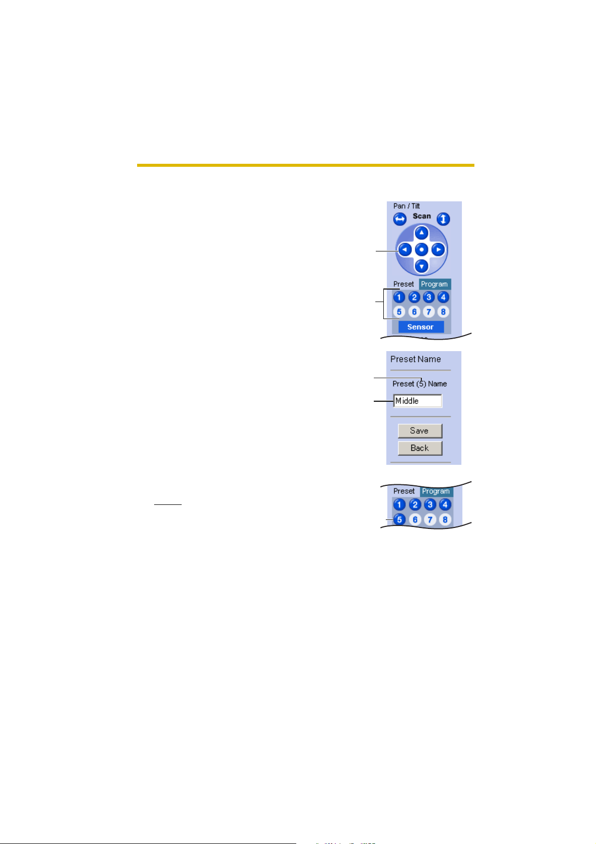
Registering a Preset Button
1.
Click [Program].
• [Program] switches to [Cancel].
Click [Cance l] to quit without s avin g
changes.
2. Pan and tilt the camera to a desired
position.
3. Click a preset button (1—8) to register.
E.g.:
Setting "Middle" for the preset 5.
4. Enter the preset name.
• Maximum 15 characters.
• Enter ASCII characters (see page
107) or characters in each
language. But [ Space], ["], ['], [&], [<]
and [>] are not available.
5. Click [Save].
• When finished, "Success!" is
displayed.
• Clicking [Back] takes you back to the
previous p age withou t changi ng the
settings.
6. Click [Back].
• The bar switches to the operation
bar.
Pan/Tilt
Preset
Preset
number
Setting
a name
18
Notes
• When registering preset buttons,
the camera also saves brightness
and white balance settings.
• Only an administrator can register
preset buttons.
The button
turns blue.
Page 19
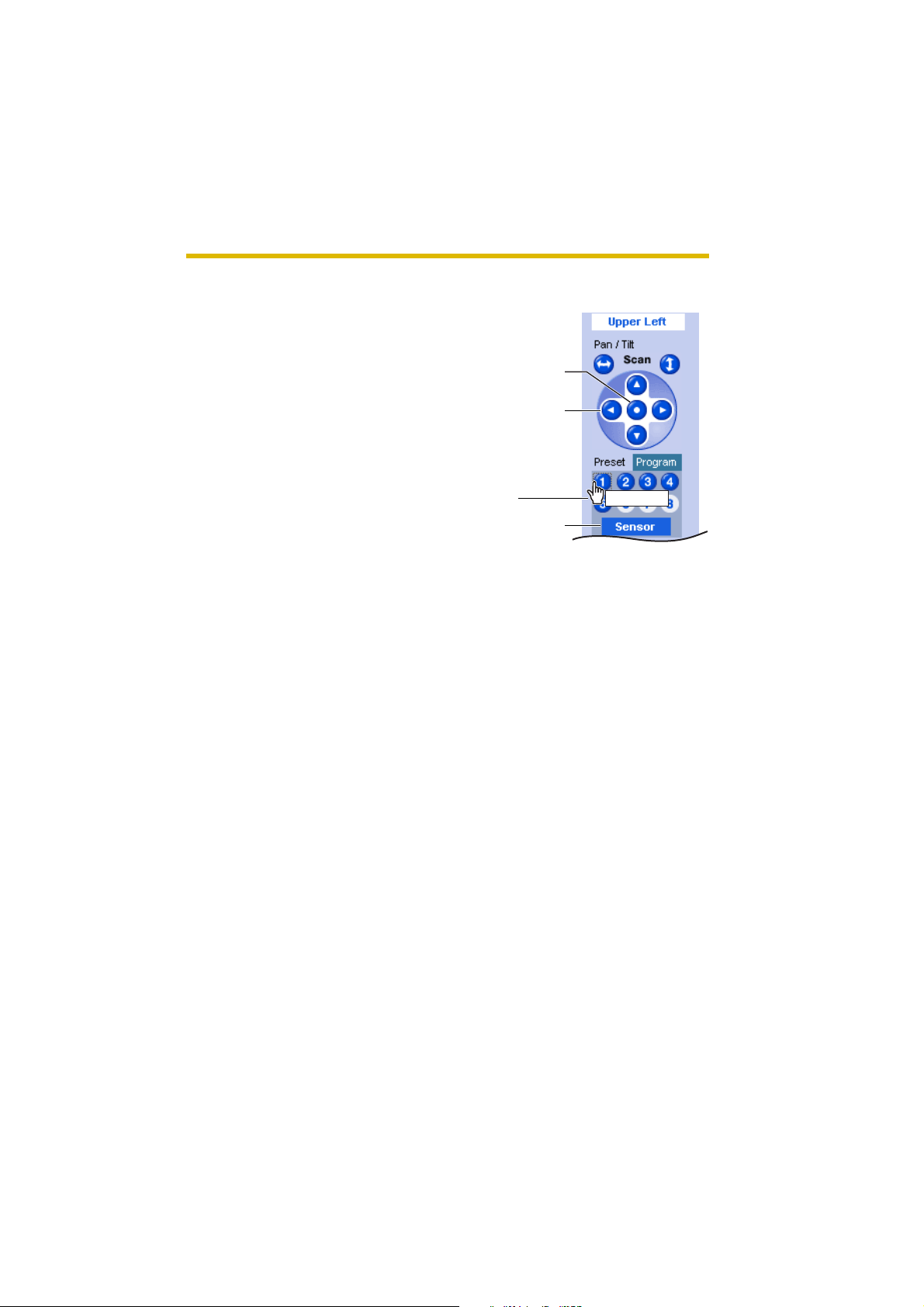
Viewing the Image
1.
Click the home position, sensor
position or registered preset button.
• The camera takes each position,
and the image is displayed.
Home
Position
Pan/Tilt
Putting the
cursor displays
the preset
name.
Sensor
Position
Operating Instructions
UpperLeft
[For assistance, please call: 1-800-272-7033] 19
Page 20
Operating Instructions
Changing or Deleting the Settings
1.
Click [Program].
• [Program] switches to [Cancel].
Click [Cance l] to quit without s avin g
changes.
2. Pan and tilt the camera to a desired
position.
3. Click the home positio n, sensor posi tion
or a preset button (1—8).
4. Click [Save] after setting the preset
name or click [Delete].
• "Success!" is displayed.
• Clicking [Back] takes you back to the
previous page.
5. Click [Back].
• The bar switches to the operation
bar.
Note
The home positio n or the sensor pos ition
cannot be deleted, and these position
names cannot be changed either.
Home
Position
Pan/Tilt
Preset
Sensor
Position
Preset
number
Changing
the name
20
The deleted
button turns
white.
Page 21
Operating Instructions
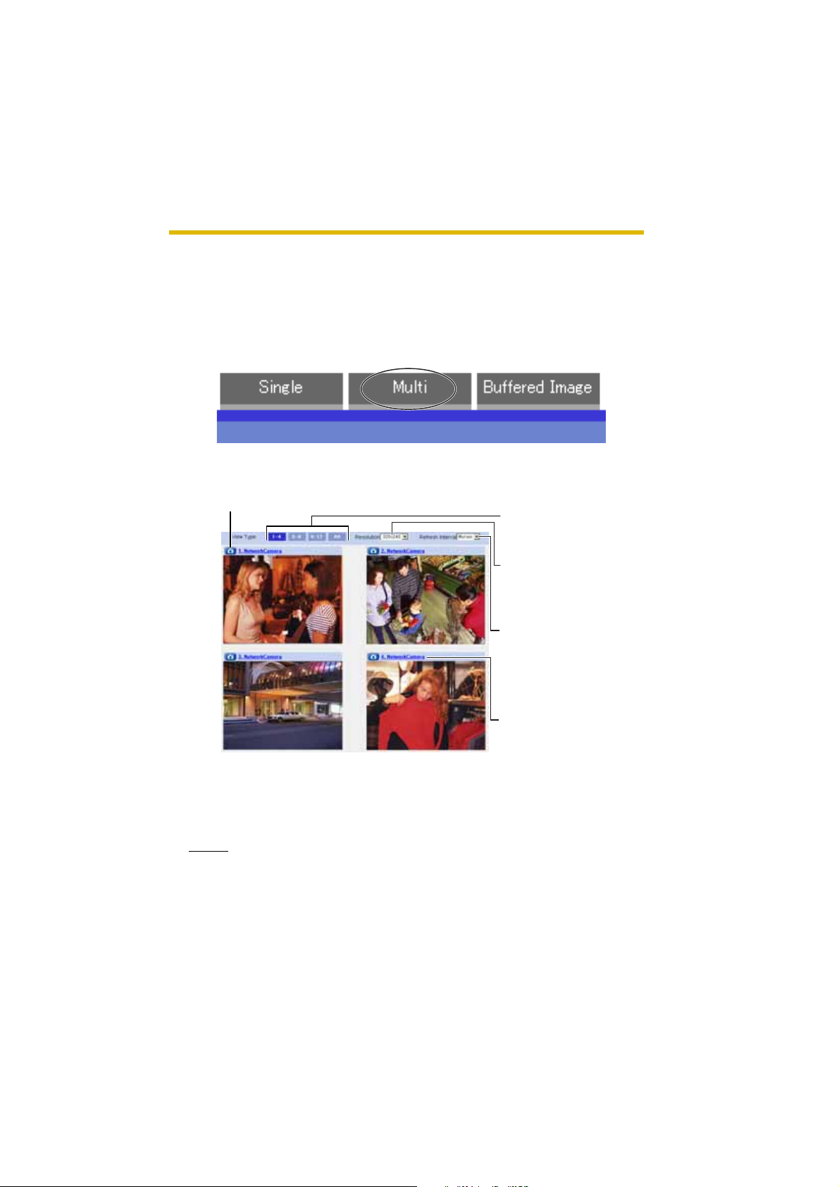
1.3 Viewing Multi-Camera page
To view multiple cameras on the Multi-Camera page, you need to configure each
camera on the Multi-Camera Setup page (see page 55).
1. Access the camera (see page 8).
• The Top page is displayed.
2. Click the [Multi] tab at the top of the page.
• Multi-Camera page can display up to 12 camera images.
Capture Image Button (see page 14)
Switches cameras to
display.
Selects [320 x 240]
(default) or [160 x 120]
pixels resolution.
Selects a refresh interval
(Motion—60-second
interval). If y ou selec t [All]
at the View Type, video
(Motion JPEG) cannot be
displayed.
When clicking the camera
name, the Single Camer a
page is displayed on
another window.
3. Close the web browser.
Notes
• When selecting [All] at the View Type, all images are displayed in 160 x
120 pixels reso lu tion .
• 640 x 480 pixels image cannot be displayed on the Multi-Camera page.
[For assistance, please call: 1-800-272-7033] 21
Page 22

Operating Instructions
• When viewing video (Motion JPEG), we recommend using an Ethernet
switching hu b inste ad of th e repea ter hub to prevent degradation in v ideo
display.
• Due to the network congestion or the number of accesses, the refresh
interval may slow down.
• When the refresh interval is slow, restrict the bandwidth on the Network
page (see page 33). The refresh interval may be improved.
• If the video (Motion JPEG) displ ay is limited (see page 52), the video will
be changed to refreshing still images.
• To reduce the data traffic, the video (Motion JPEG) can be automatically
changed to refreshing still images (see page 52).
• When viewing 4 came ras on the Mul ti-Came ra page , y ou m ay need 3 to 4
Mbps bandwidth. If the ba ndwi dth is no t enoug h, the refre sh inte rval may
slow down.
®
When the image is not displayed on the Multi-Camera page
• Confirm that the Internet IP address is specifie d for each c amera and that e ach
camera is connected to the Internet. For Internet access, local IP addresses
(192.168.xxx.xxx) cannot be used.
• Confirm the settings on the Multi-Came ra Setup page (see page 55).
• Confirm that the web browser is not accessing the proxy server (see page
103).
How to save a still image to y our PC
On the Single Camera or Multi-Camera page
• A still image can be saved using the capture image button (see page 14).
On the Buffered Image page
• A still image can be saved on the Buffered Ima ge pa ge, if you are not playing
images on it. Put t he cu rsor on the i mage , a nd righ t-clic k i t. Then sele ct [Sa v e
Picture As...].
When setting [Do not permit unregist ered users] o n the Security:
Administrator page
• An authentication window is displayed in camera access. Enter the
administrator's or the general user's user name and password.
• When you view the images on the Multi-Camera page, all authentication
windows of the configured cameras are displayed. Enter the administrator's or
the general user's user name and password registered for each camera.
22
Page 23
Operating Instructions
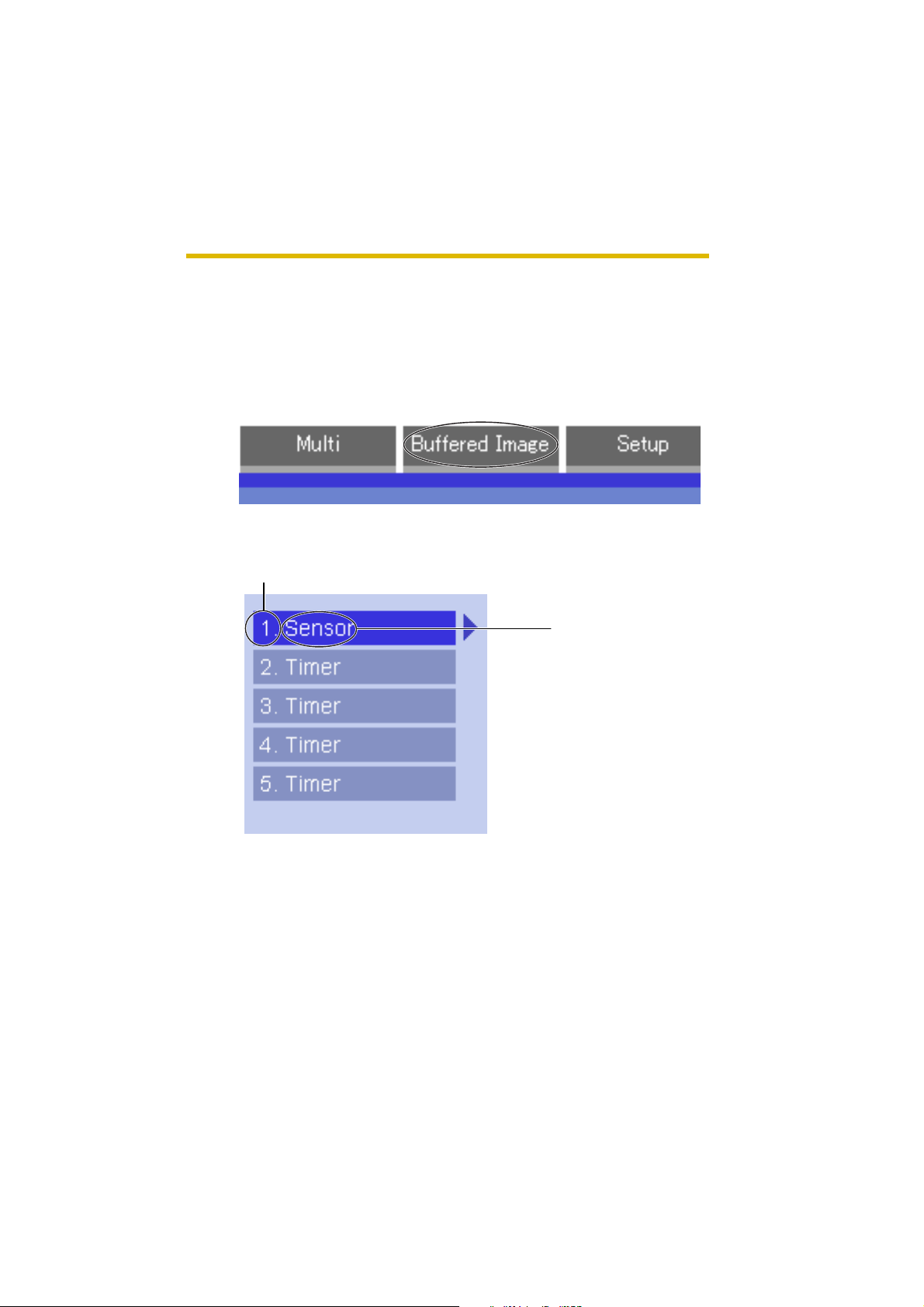
1.4 Viewing Buffered Image page
To buffer the images on the internal memory, you need to set up image transfer
settings (see page 57 or page 64). You can view buffered images on th is Buffered
Image page.
1. Access the camera (see page 8).
• The Top page is displayed.
2. Click the [Buffered Image] tab at the top of the page.
3. Click the tr igger number.
The trigger number is displayed (see page 57 or page 64).
The trigger is displ ayed
(see page 57 or page 64).
[For assistance, please call: 1-800-272-7033] 23
Page 24

Operating Instructions
4. Display im ages clicking buttons below.
Date and time of the day when the
images were buffered are displayed.
Date, time and frame number are
displayed.
[Play]:
The buffered images are displayed
continuously.
[<Prev] or [Next>]:
The previous or next image is
displayed.
[<10] or [10>]:
The 10th image before or after the
current image is displayed.
[<100] or [100>]:
The 100th image before or after the
current image is displayed.
Notes
• Date, Time and frame number are not displayed in play mode.
• Maximum numb er of buff ered ima ges change de pending on res olution, imag e
quality and what o bje ct the camera buffers. At t he 3 20 x 240 pixels resolution
and the standard quality, the camera buffers about 250 fra mes (see page 108).
(If 3 trigger settings are enab le d, the in ternal mem ory capacit y is divi ded into
3 sections. In this case, each trigger can buffer about 80 frames.)
1.4.1 Deleting Buffered Images
If you intend to delete images for each transfer condition, click [Delete Buffered
Images] on the Image Buffer/Transfer page (see page 57 or page 64).
Notes
• When you change settings (except for Enable/Disable settings) on the Image
Buffer/Transfer page, the buffered images only for that trigger will be deleted.
• The following operations also delete all buffered images.
• Turning off the camera.
• Saving the Date and Time page.
• Restarting, updating firmware or resetting the camera to factory default.
• Changing the Enable/Di sable set tings of Image Buff er/Transfer (see page
57 or page 64).
24
Page 25
Operating Instructions
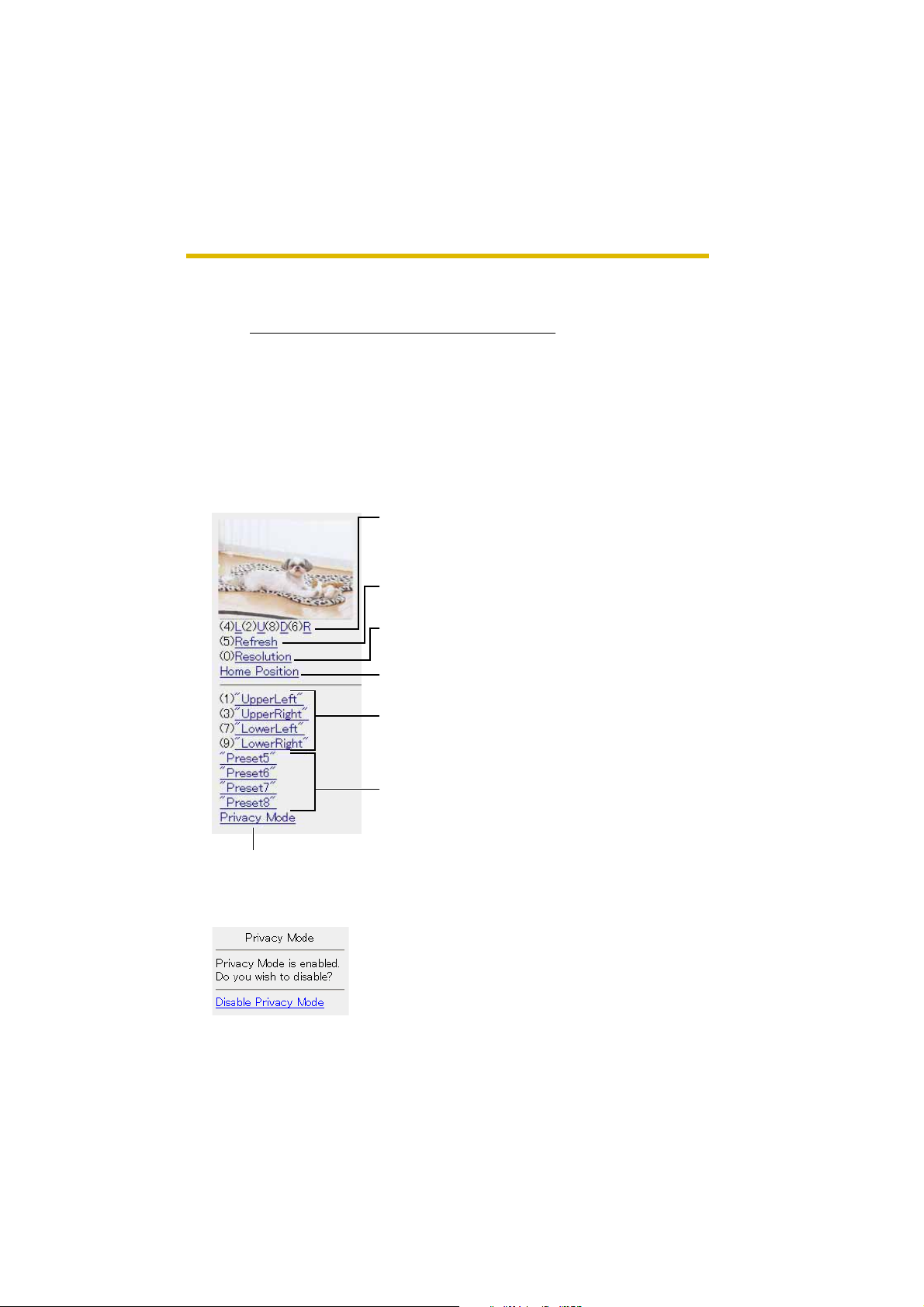
1.5 Viewing Still Images on Your Mobile Phone
You can view still images over the Internet from a compatible mobile phone.
Enter "http://IP address (or URL):Port Number/mobile
press [OK].
• When the port number is set to 80 (default), it is not required.
E.g. http://XXX.XXX.XXX.XXX:50000/mobile
(or XXXXX.viewnetcam.com:50000/mobile)
• When an authentication window is displayed, enter the administrator's or the
general user's user name and password.
• A still image is displayed. (Video [Motion JPEG] cannot be displayed.)
Pressing 2, 4, 6 or 8 on the mobile phones allows
you to pan or tilt the camera in four directions:
Left, Up, Down or Right.
Pressing 5 will refresh the image.
160 x 120 resolution is displayed at the first
access. Pressi ng 0 switches th e resolution to 320
x 240.
Executing [Home Position] moves the lens to the
home position.
Pressing 1, 3, 7 or 9 o n t he k e ypa d allo w s yo u t o
use the firs t four registered preset buttons.
" on a mobile phone and
Registered presets 5—8 are available by
activating the link on the mobile phone page.
If you e xec ute [Privacy M ode] here, the camera sw itches to priv acy mode . To
disable it, a ccess the camer a again and e xe cute [Disabl e Privacy Mo de] (see
page 77).
[For assistance, please call: 1-800-272-7033] 25
Page 26

Operating Instructions
Notes
• If the image is not displayed properly, try the following 2 URLs.
1. http:// IP address(or URL):Port Number/mobileh
(or XXXXX.viewnetcam.com:50000/mobileh)
2. http:// IP address(or URL):Port Number/mobilex
(or XXXXX.viewnetcam.com:50000/mobilex)
• Only an administrator can control privacy mode.
• In privacy mode, sensor and timer image buffer/transfer features also are
stopped.
• When ex ecuting [Priv acy Mode] while s etting [Allo wing unregistere d users] on
the Security: Administrator page (see page 46), an authentication window is
displayed. Log in to the camera as an administrator.
• If the users are restricted to level 1 or 2 on the General User page (see page
50), the users do not see some kinds of buttons.
• When pan/tilt reaches the end, the keypad number and character disappear.
E.g.: The pan reaches the left end.
"(4)L" disappears.
• Some mobile phones are not compatible with Panasonic Network Cameras.
Some phones may allow viewing only on port 80, and some may not support
password authentication. See the Panasonic Network Camera support
website at http://panasonic.co.jp/pcc/products/en/netwkcam/ for a mobile
phone model list, and the compatibility level which has been verified with the
Panasonic Network Camera.
• Some mobile phones display images not at the specified resolution but at a
decreased size.
for HTML.
for XHTML.
Stopping E-mail Transfer by the Mobile Phone Operation
Executing privacy mode on a mobile phone operation can stop E-mail transfer.
1. Access the camera from a mobile phone (see page 25) and log in to the
camera as an administ ra tor.
2. Execute [Privacy Mode] (see page 25).
• The camera switches to privacy mode and stops E-mail transfer (Image
Buffer/Transfer).
26
Page 27

2 Various Camera Features
2.1 Using Camera Features
1. Access the camera (see page 8).
Notes
• When [Allowing unregistered users] is set on the Security: Administrator
page, click [login] tab and log in as an administrator.
• When users other than an administrator are accessing the camera, the
[Setup] and [Maintenance] tabs are not displayed.
• The Top page is displayed.
2. Click [Setup] tab at the top of the page.
(1)
(2)
(3)
(4)
(5)
(6)
(7)
(8)
Operating Instructions
(9)
(10)
(11)
(12)
(13)
(14)
[For assistance, please call: 1-800-272-7033] 27
Page 28

Operating Instructions
Basic
(1) Network Configures the netw ork sett ing s su ch as connection mode
to connect the camera to the network (see page 30).
(2) Wireless Configures wireless network (see page 34).
(3) UPnP Enables automatic port forwarding or shortcut to the
camera (see page 37).
(4) Viewnetcam.
Registers with the Viewnetcam.com service (see page 38).
com
(5) Date and Time Sets the date and time, automatic time adjustment and
adjust clock for daylight saving time settings (see page 40).
(6) Camera Sets camera name, white balance, AC power source
frequency and pan/tilt range (see page 42).
Account
*1
(7) Administrator
Sets authenticatio n setting and adminis trator security (user
name and password) (see page 46).
*1
(8) General User
Sets general user secu rity (use r nam e and password) and
general user's feature restriction (see page 50).
Advanced
(9) Image Display Sets resolution, image quality and refresh interval of Single
Camera and Multi-Camera page, limit continuous motion
*1
, and language (see page 52).
JPEG
*1
(10) Multi-Camera
Sets the camera IP address or host name, camera name on
the Multi-Camera pa ge (m ax imum 12 cameras) (see page
55).
(11) Buffer/Transfer Sets image buff er or trans f er b y time r or senso r. (see page
57 or page 64).
(12) Operation
Sets time period to display camera images (see page 74).
Time
*1
If you change [Administrator], [General User], [Limit Continuous Motion JPEG] or [MultiCamera Setup page] settings, changes will not be applied to the video (Motion JPEG)
viewers. Restart the camera to make changes applied to all video viewers.
28
Page 29

Operating Instructions
(13) Indicator
Sets indicator display (see page 76).
Control
(14) Privacy Mode Enables privacy mode (see page 77).
[For assistance, please call: 1-800-272-7033] 29
Page 30
Operating Instructions
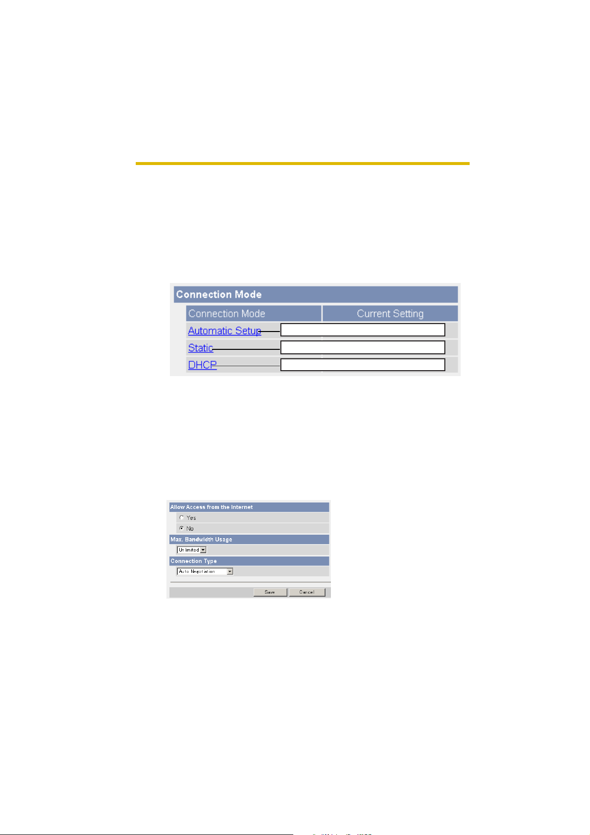
2.2 Connecting the Camera to Your Network
The Network page offers three options to configure the camera.
• [Automatic Setup] automatic ally assigns an unused IP addre ss to the camer a,
and uses UPnP to configure your router.
• [Static] allows the user to use a specific IP address.
• [DHCP] is offered for ISPs who require this option.
1. Click [Network] on the Setup page.
2. Select a connection mode.
Normally sets Automatic Setup.
Uses a static IP address.
Uses ISP DHCP server function.
• Each page is displayed (see page 30—page 31).
3. Enter each parameter in the proper data field.
Automatic Setup
The camera aut om atic al ly ob tai ns the network settings (subnet mask, default
gatewa y and DNS server address) uti lizing a DHCP f eatu re on the route r . The
camera also automatic al ly searc he s the un u se d IP addres s on y ou r network.
If you select [Yes] at the Allow Access from the Internet, the camera
automatically en ables p ort forwarding by using U PnP. In this case, the camera
automatically searches the unused port number on your network in the order
from 50000 to 50050.
30
• Clicking [Cancel] takes you back to the previous page without saving
changes.
Page 31
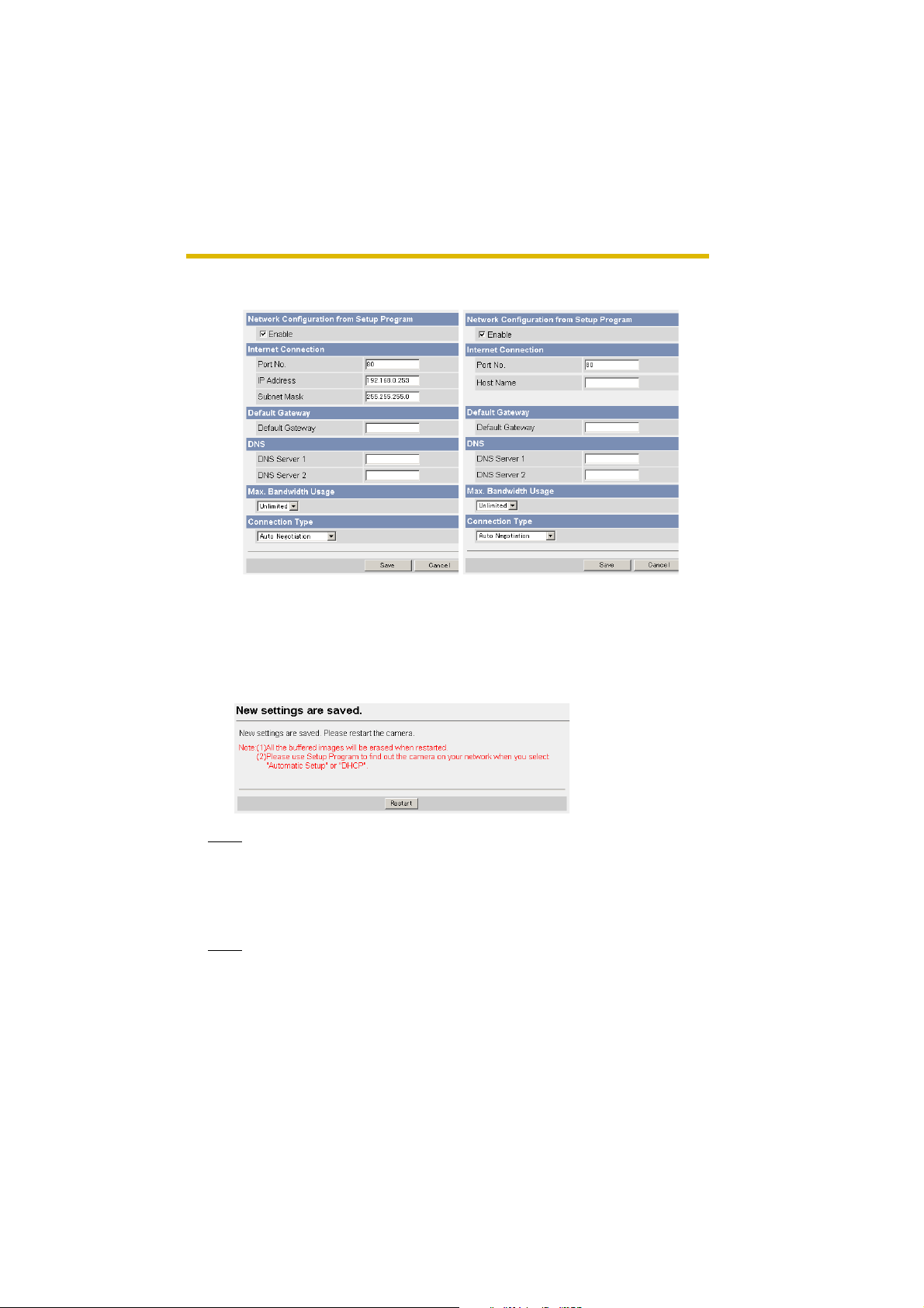
Static Setup DHCP Setup
• Clicking [Cancel] takes you back to the previous page without
saving changes.
4. Click [Save] when finished.
• New settings are saved.
• When finished, the following page is displayed.
Operating Instructions
Note
The current network settings are shown on the Status page in the Maintenance
section (se e page 79).
5. Click [Restart].
• The camera restarts, and the Top page is displayed.
Note
When you do not kno w the camera IP address while se tting [A utomatic Setup]
or [DHCP Setup], you can search the camera IP address by using the Setup
Program (see page 100).
[For assistance, please call: 1-800-272-7033] 31
Page 32

Operating Instructions
Setting Description
Allow Access from
the Internet
(Automatic Setup
Only)
Network
Configuration from
Setup Program
(Static/DHCP Only)
Port Nu mber
(Static/DHCP Only)
• IP address
• Subnet Mask
(Static Only)
• Allow Access from the Internet setting automatically
configures the router's Port Forwarding setting (some
routers call it "Address Translation", "Static IP
Masquerade", "Virtual Server" or "Port Mapping"). To
enable Internet access to the camera, check [Yes]. In this
case, the camera automatically searches the unused port
number on yo ur network in th e order from 5 0000 to 50050.
To disable Internet access to the camera, check [No].
• If you prohibit the Setup Program from changing the
network settings, clear the check box.
• You can set the camera port number (80 by def ault). When
you use multiple cameras with a router on your network,
each camera must be assigned its own port number (see
page 11 "1.5 Connecting the Camera to a Router Not
Supporting UPnP" in the Installation/Troubleshooting).
• Do not set the following port numbers.
E.g., FTP: 20 and 21, Telnet: 23, SMTP: 25, DNS: 53,
POP3: 110, HTTPS:443, ICQ: 4 000 and IRC: 6661—66 67.
• Enter only the numbe r (1—65535).
• Some ISPs do not allow you to use port 80. Ask your ISP
or network admini strator about the accessib le port number
over the Internet.
• If your ISP or network administrator specifies the IP
address and subnet mask, enter them in each data field.
• If you use the c amera on the L AN, set the IP ad dress in the
same class as your PC (see page 99).
• Set 4 digits (0—255) and 3 periods such as
"192.168.0.253". But "0. 0.0.0" an d "255.25 5.255. 255 " are
not available.
Host Name
(DHCP Only)
32
• If your ISP uses the DHCP function which automatically
assigns the IP address to the camera, enter the ISPassigned host name. (Host name may be used as an
authentication.)
• Enter ASCII characters f or the host n ame (see page 1 07).
But [Space], ["], ['], [&], [<] and [>] are not available.
Page 33

Setting Description
Default Gateway
(Static/DHCP Only)
*1
• If you ha v e the assigned Def ault Ga te wa y addre ss b y y our
ISP or network administrator, enter it in this data field.
• Set 4 digits (0—255) and 3 periods such as
"192.168.0.253". But "0.0.0.0" and "255.255.255.255" are
not available.
Operating Instructions
DNS Server
Address
*1
(Static/DHCP Only)
• DNS server address is required in the f oll owing c ondition s.
• Transferring camera images by E-mail or FTP
• Setting cameras by their host names on the Multi-
Camera Setup page
• Using the Viewnetcam.com service
• If you have the assigned DNS server addresses by your
ISP or network administ ra tor, enter them in this data fiel d.
They usually have two addresses.
• Set 4 digits (0—255) and 3 periods such as
"192.168.0.253". But "0.0.0.0" and "255.255.255.255" are
not available.
Max. Bandwidth
Usage
• The bandwidth can be restricted.
• Select the maximum bandwidth usage from [Unlimited] to
[0.1 Mbps].
Note
Set the maximum bandwidth usage seei ng the following
file sizes. These are exampl es for a JPEG file with a
standard image qualit y. File sizes may change depending
on the image quality or how bright the object is.
160 x 120 pixels: About 3 KB (24 Kbit)
320 x 240 pixels: About 10 KB (80 Kbit)
640 x 480 pixels: About 18 KB (144 Kbit)
Connection Type • Normally, Select [Auto Negotiation]. For the wireless
connection, [Au t o Nego tiation] must be selected. If you
cannot access the camer a, see pag e 20 "The Top page is
not displayed." in the Installation/Troubleshooting.
*1
If you automatically obtain the IP address from the DHCP server, you do not need to set it.
[For assistance, please call: 1-800-272-7033] 33
Page 34

Operating Instructions
2.3 Using Wireless LAN
Wireless communication is possible by adjusting the settings of the wireless LAN
to those for the router. Take a note of the settings and save them for reference. For
more information about wireless setting, please refer to http://panasonic.co.jp/
pcc/products/en/netwkcam/technic/wireless/cam_set.html
1. Click [Wireless] on the Setup page.
2. Set each parameter for the Wireless Configuration.
Setting Description
SSID • The SSID must be set to match the SSID your router or
wireless LAN uses. The SSID is limited to 32 characters
(alpha numeric) and is case sensitive.
34
Communication
mode
• In "802.11b", the re are a lot o f 802.11b-comp liant products
and they are inexpensive. They are widely prevalent, so
"802.11b" is useful when using your existing wireless
devices.
• "802.11b/g" supports both 802.11b and 802.11g wireless
LAN standards. It is the c omm unic ation mode that is easy
to install on your existing wireless LAN.
• "802.11g exclusive" communicates using 802.11g only. It
does not support the mixed standard mode of 802.11b/g,
so it allows the use of original features of 802.11g.
*1
Even if "802.11g exclusive" is in use, the existence of other wireless devices using 2.4
GHz bandwidth —including 802.11b wireless devices— makes the baud rate of 802.11g
slower.
*1
Page 35
Operating Instructions
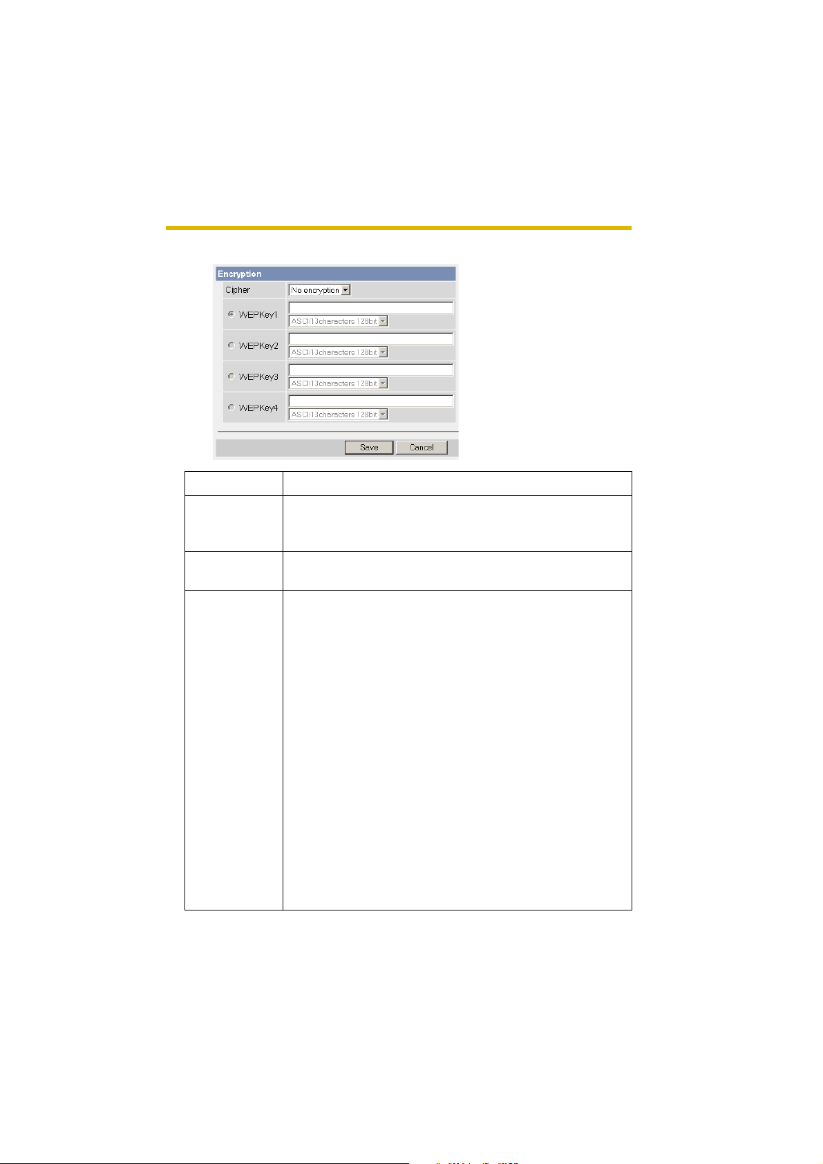
3. Set each parameter for the Encryption.
Setting Description
Cipher • Select encrypting or not encrypting.
• T o pre vent unauthoriz ed users from reading data , selecting
[WEP] is recommended.
WEP Selection • Checked WEPKey is used as a s tan da rd WE PKey . C he ck
the same number as the router.
WEPKey1—4 • Select one from [HEX, 10 characters 64 bit], [HEX, 26
characters 128 bit] , [HEX, 32 ch arac ters 152 b it], [ASCII 5
characters 64 bit], [ASCII 13 char a cte rs 12 8 bit] or [AS CII
16 characters 152 bit] on the list.
• Selecting [WEP] at Ciph er e na b l es you to set WEPKey 1—
4. One or all of the four keys can be set. Check the same
key number as set to the router, and set the same key as
at the router.
<Example>
HEX, 10 characters 64 bit : 012345abcd
HEX, 26 characters 128 bit : 0123456789abcdef012
345abcd
HEX, 32 characters 152 bit : 0123456789abcdef012
3456789abcdef
ASCII 5 characters 64 bit : 012yz
ASCII 13 characters 128 bit : 0123456uvwxyz
ASCII 16 characters 152 bit : 0123456789uvwxyz
[For assistance, please call: 1-800-272-7033] 35
Page 36

Operating Instructions
Notes
• Some wireless devices do not support the WEP 152 bit.
• The camera supp orts only the open syst em authentic ation. If the router or
access point is set to shared key authentication, set it to auto or open
system.
4. Click [Save] when finished.
• New settings are saved.
• When finished, "Success!" is displayed.
5. Click [Go to Wireless configuration page].
• The Wireless page is displayed.
6. Set the switch to WIRELESS.
Notes
• It takes about 1 mi nute for the new settings to be effective.
• It is not possible to access the camera simultaneously by both wired and
wireless connection.
• To communicate using wireless connection, set up the camera by using
wired connection and set the switch from wired to wireless as shown
below.
• When you s witch wired t o wireless or vi ce versa, rest art the camera. Some
routers also may need to be restarted after switching.
< Bottom >
36
Switch
WIRELESS
WIRED
Page 37
Operating Instructions
2.4 Using UPnP (Universal Plug and Play)
UPnP can automatically configure your ro uter to be acces sed from the In ternet. In
order to use this feature, your router needs to support this feature and it must be
enabled. Most router manuf act urers disab le th is f eature as the def ault set ting. S ee
http://panasonic.co.jp/pcc/products/en/netwkcam/technic/rtr_setup for
details and see your router manual for how to enable UPnP. After the UPnP is
enabled on the router, set [Enable] for auto port forwarding.
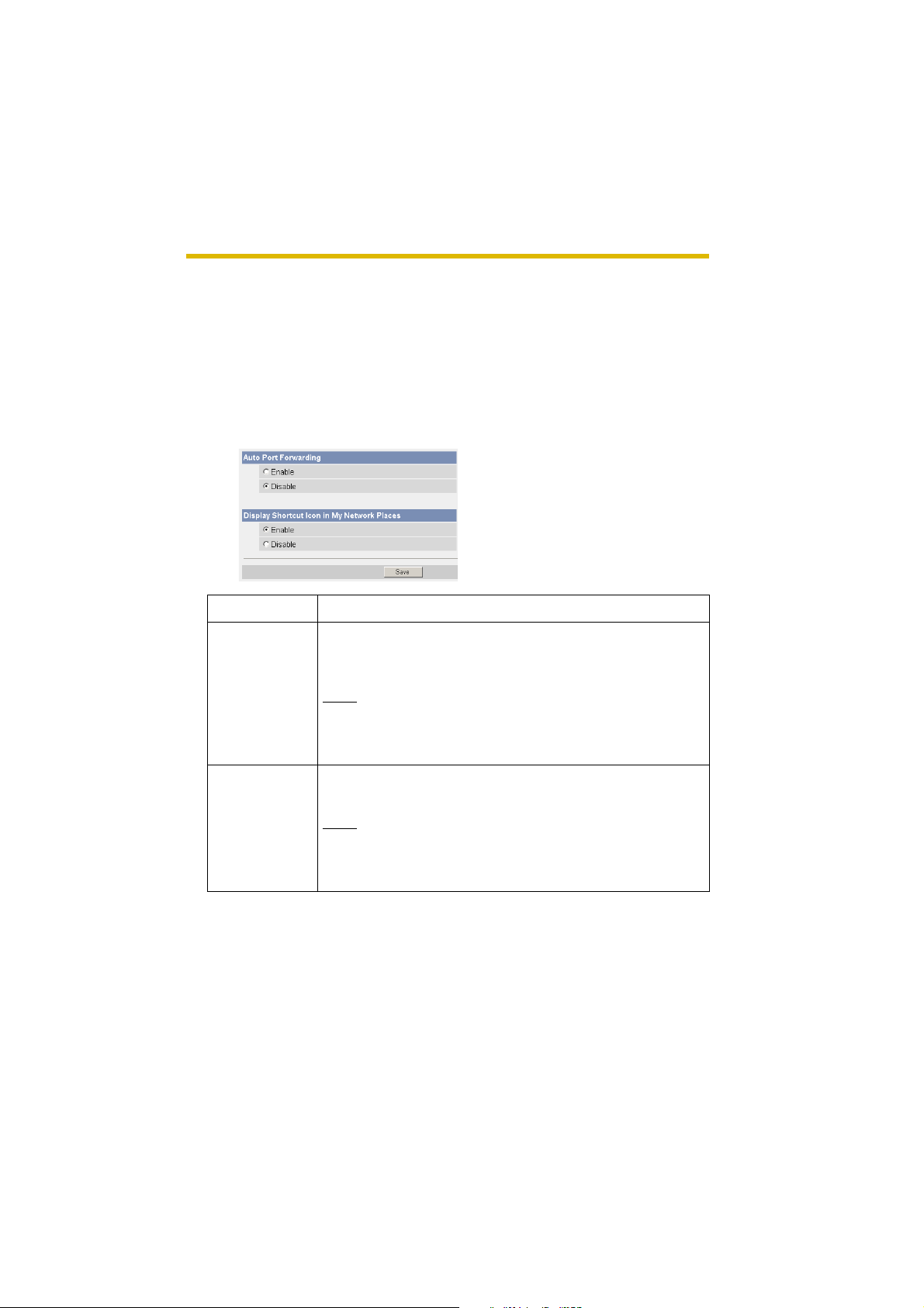
1. Click [UPnP] on the Setup page.
2. Set up UPnP.
Setting Description
Auto Port
Forwarding
• If the network setting is [Static] or [DHCP], enabling auto
port forwarding allows you to access the camera from the
Internet.
Note
If the network setting is [Automatic Setup], enable [Allow
Access from the Inte rnet] on t he Ne tw o rk page (see page
32).
Display Shortcut
Icon in My
Network Places
• Enabling it displays a shortcut to the camera in the My
Network Places folder.
Note
If you use Windows XP or Windows Me, this feature is
availa ble. Enab le UPnP Windo ws component be fore using
this feature (see page 106).
3. Click [Save] when finished.
• New settings are saved.
• When finished, "Success!" is displayed.
4. Click [Go to UPnP page].
• The UPnP page is displayed.
[For assistance, please call: 1-800-272-7033] 37
Page 38

Operating Instructions
2.5 Registering with the Viewnetcam.com service
Viewnetcam.co m is a free se rvice (dynamic DNS service) t hat allows y ou to ass ign
an easy to remember name to the camera, similar to your favorite web site.
Viewnetcam.co m also allows y ou to easily access the camera, e ven when yo ur ISP
changes the IP address . P ana sonic Com municati ons recom mends y ou to reg ister
with it for the Internet access to the camera. See http://www.viewnetcam.com for
details about the Viewne tca m.c om service.
1. Click [Viewnetcam.com] on the Setup page.
2. Check [Enabl e].
• Clicking [Cancel] cancels your settings without saving changes.
Setting Description
Enable • Check [Enable] to regis ter with the Viewnetcam.com
service. If yo u clear the box, the View ne tca m.com service
stops.
38
Personal
(Camera) URL
Your Account
Link
• The camera's personal URL will be displayed after you
register with the Viewnetca m.com service.
• The URL is displayed to register with the Viewnetcam.com
service. Clicking [Your Account Link] item name displays
the Viewnetcam.com registration we bsite.
3. Click [Save] when finished.
• New settings are saved.
• When finished, "Success!" is displayed.
4. Click [Go to Viewnetcam.com page].
• The Viewnetcam.com page is displayed.
5. Click [Your Account Link].
• The Viewnetcam.com registration website is displayed.
Page 39

Operating Instructions
Notes
• When the Viewnetcam.com registration website i s n ot d is played, confirm
that the URL is displayed in the right column of the Your Account Link. If
the URL is not displayed, follow the procedures below.
1. Wait for a while, and click [Refresh] on the web browser.
2. Confirm that your network (your PC and camera) is connected to the
Internet.
• Personal (Camera) URL is available after you registered with the
Viewnetcam.com service.
• If port forwarding is not enabled or your network is not connected to the
Internet, the Viewnetcam.com service is not available.
6. Register with the Viewnetcam.com service following the website.
• The Viewnetcam.com page is displayed .
7. Access the camera with a registered URL from the Internet (see page 8).
• When the Top page is displayed, the Viewnetcam.com registration is
complete.
Notes
• It may take a maximum of 30 minutes for the registered URL to work.
• If "Expired" is displayed at the Personal (Camera) URL on the
Viewnetcam.com page or at the Camera URL in the DDNS on the St atus
page, restart the camera. After that, confirm that your registered URL is
displayed on their pages.
Confirming the Internet access
Due to the router specifica tions, the image m ay not be displa yed e ven if y ou access
the camera from y our PC on the same LAN as the came ra. In this case , access the
camera following procedures.
• Accessing from the PC on another network (see page 8)
• Accessing from your mobile phone (see page 25)
[For assistance, please call: 1-800-272-7033] 39
Page 40
Operating Instructions
2.6 Setting Date and Time
The Date and Time page allo ws y ou to set date and time . Date and tim e are used
for image buffer/transfer, operation time and time stamps on the buffered image.
Note
Saving the date and time settings deletes all buffered images.
1. Click [Date and Time] on the Setup page.
2. Set each parameter.
40
• Clicking [Cancel] cancels your settings without saving changes.
Page 41

Operating Instructions
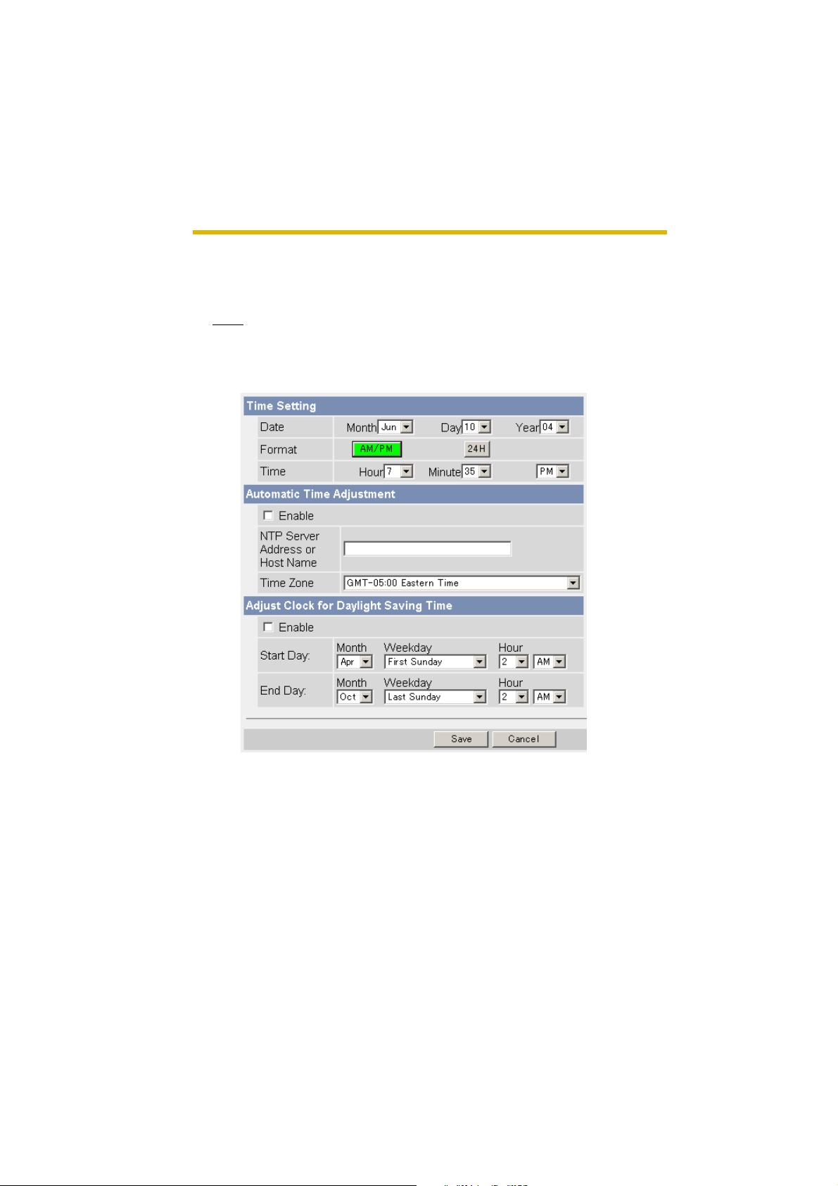
Setting Description
Time Setting • Select date and format (AM/PM or 24 H). These settings
are used f or image b uff er/tra nsf er , operati on time and tim e
stamps on the buffered image. But E-mail subject and file
name by E-mail or FTP transfer uses only 24 h format.
Automatic Tim e
Adjustment
• NTP (Network Time Protocol) server synchronizes the
camera's internal clock. It adjusts automatically every day .
Check the box to enable it.
• Set the NTP server IP address , set 4 digits (0—255) and 3
periods such as "192.168.0.253". But "0.0.0.0" and
"255.255.255.255" are not available. Or set a host name
(1—255 characters).
• Select your time zone.
Note
If the time is incorrect by more than one hour, Automatic
Time Adjustment stops working to prevent malfunctions
caused by a disguised NTP server.
Adjust Clock for
Daylight Saving
Time
• During the da ylight s aving time, the internal cloc k is turned
forward an hour . The clock will shift one h our forw ard at the
set time on the Start Day, and move back one hour at the
set time on the End Day. Check the box to enable it.
Note
An "s" is put between date and time of time stamp when
enabling this feature. The time stamp will be attached to
the transferred images by the Image Transfer feature.
3. Click [Save] when finished.
• New settings are saved.
• When finished, "Success!" is displayed.
4. Click [Go to Date and Time page].
• The Date and Time page is displayed.
Note
Date and time setti ngs become i ncorrect depe nding on the length of po wer-on
time or the internal temperature. Using the Automatic Time Adjustment is
recommended.
[For assistance, please call: 1-800-272-7033] 41
Page 42

Operating Instructions
2.7 Changing Camera Settings
The Camera page allows you to set the camera name, white balance, AC power
source frequency and pan/tilt range.
1. Click [Camera] on the Setup page.
2. Set each parameter.
42
• Clicking [Cancel] cancels your settings without saving changes.
Page 43

Operating Instructions
Setting Description
Camera Name • The camera name is displayed on the Single Camera
page.
• Enter ASCII characters (see page 107) or characters in
each language (1—15 characters for a 1-byte character
and 1—7 characters for a 2-byte character). But [Space],
["], ['], [&], [<], and [>] are not available.
White Balance Select from the following options.
• Auto (default) — Automatic adjustment
• Fixed Indoor — Electric bulb (2800 K)
AC Power
Source
Frequency
Pan Range
• Fixed Fluorescent
— White (3600 K)
(White)
• Fixed Fluorescent
— Daylight (400 0 K)
(Daylight)
• Fixed Outdoor — Solar light (6000 K)
• Hold — Setting [Hold] keeps the current
white balance.
Note
White balance is also saved in the home position, sensor
position and preset buttons.
• In some cases, the image may have noise due to
fluorescent light. Select 60 Hz for the United States.
•50 Hz
• 60 Hz (default)
*1
Select from the following options.
• Minimum — Current settings, -50—+50
• Home Position
• Maximum — Current settings, -50—+50
• The values must be selected as minimum home
position maximum.
*2
— Current settings, -50—+50
[For assistance, please call: 1-800-272-7033] 43
Page 44

Operating Instructions
Setting Description
Tilt Range
*1
Select from the following options.
• Minimum — Current settings, - 40—+10
*2
• Home Po si tio n
— Current settings, -40—+10
• Maximum — Current settings, -40—+10
• The values must be selected as minimum home
position maximum.
*1
See page 45 for details about pan/tilt range settings.
*2
These home position settings are displayed as you set on page 17.
3. Click [Save] when finished.
• New settings are sav ed. If the hom e position is c hanged, the cam era turns
to the home position.
• When finished, "Success!" is displayed.
4. Click [Go to Camera page].
• The Camera page is displayed.
44
Page 45

Operating Instructions
Specifying Pan/Tilt Range
1.
Access the camer a (see page 8), and click [Single] a t th e t op of the Top pa ge.
2. Open another web browser, and display the Camera page (see page 42).
3. Align the Single Camera page and the Camera page side to side.
4. Set the pan/tilt range.
• Selecting [Current] di sp lays the current angle of the camera. Select each
value while adjusting the pan/tilt on the Single Camera page.
Note
The values must be selected as minimum home position maximum.
Max.: +10 °
Max.: +50 °
Min.: -40 °
Min.: -50 °
5. Click [Save] on the Camera page.
• New settings are saved. The camera turns to the home position.
[For assistance, please call: 1-800-272-7033] 45
Page 46

Operating Instructions
2.8 Changing Authentication Setting and
Administrator User Name and Password
The Security: Administrator page allows you to change authentication,
administrator user name and password. The authentication window is displayed,
and allows the registered users to access the camera.
Notes
• If you access the c amera f or the first time, th e window to set ad ministrator user
name and pass word is displ aye d. Make a note of the user name a nd pass word
so that you will not forget them.
• The user name and password should be secured at your own responsibility.
Pa y atte ntion to the followi ng points.
• Set the user name and password as many characters as possible.
• Change the password regularly.
• Setting [Permit access from guest users] (permitting access without a User
Name or P as sword) at General Authentication risks the images bei ng v iewed
by third parties. Control the contents of the images accordingly.
IMPORTANT
• It is important to limit ac cess to the camera by use of a unique Us er Name and
a secret P assword. Because the camer a is acces sed t hrough the In ternet it is
possible tha t the camera could be accessed b y unknown indiv iduals, incl uding
those who are commonly known as "hackers," to whom you do not want to
allow access. The use of a unique User Name and a Password known only to
you will help insure that only authorized individuals are given access to the
camera. You have the option of proceeding without a User Name and
Password, but it is strongly recommended that you utilize these protections.
1. Click [Administrator] on the Setup page.
2. Set each parameter.
46
• Clicking [Cancel] cancels your settings without saving changes.
Page 47

Setting Description
Operating Instructions
General
Authentication
User Name/
Password
Authentication has 2 phases.
• If you set [Permit access from guest users], the camera
does not display the authentication window in camera
access. All guest users can view the image without user
name and password.
Note
If you set [Permit access from guest users], [Login] is
displayed at the top of the page. After you log in as an
administrator (see page 49), you can access the Setup
page and the Maintenance page.
• If you set [Do not permit access from guest users], the
camera displays authentication window in camera access.
Users must enter the user name and password.
• User Name (6 to 15 characters): Enter the user name.
• Password (6 to 15 characters): Enter the password.
Notes
• The password must be different from the user name.
• User name and password are case sensitive.
• Retype Password: Reenter the password.
• Enter ASCII characters (see pa ge 107). But [Space], ["], ['],
[&], [<], [>] and [:] are no t available.
Note
When users other than an administra tor are acc es sing the came ra , [Setup]
and [Maintenance] tab will not be displayed.
3. Click [Save] when finished.
• New settings are saved.
• When finished, "Success!" is displayed.
[For assistance, please call: 1-800-272-7033] 47
Page 48

Operating Instructions
4. Click [Go to Security: Administrator page].
• The Security: Administrator page is displayed.
Notes
• When the user name and password have been changed, the camera
displays an authentication window. Enter the user name and password,
and click [OK].
Administrator/General Users/Guest Users
The camera has 3 us er levels (administrator, general users and guest users).
Items Administrator General Users Guest Users
48
User Name and
Password
Number of Users 1 50 —
Accessible Pa ges All Pages Pages Ex cept F or
Access Le vel 1—3 All Operations Access leve l can
Required Required Not Required
Pages Except For
Setup and
Maintenance page
be set for each
general user (see
page 50).
Setup and
Maintenance page
Access level can
be set for guest
users (see page
50).
Note
Guest users mean unregistered users. Set [Permit access from guest users]
on the Security: Administrator page (see page 46).
Page 49

Operating Instructions
2.9 Logging in to the Camera
If you set [Permit access from guest users] on the Security: Administrator page,
[Login] is displa yed at the top of the page. Afte r you log in as an adminis trator , you
can access the Setup page and the Maintenance page.
1. Click [Login] at the top of the page.
2. Check the login mode, and click [Login].
Note
The authentication window is displayed. Enter the user name and password.
3. Enter the user name and password, and click [OK].
• You can log in to the camera.
[For assistance, please call: 1-800-272-7033] 49
Page 50

Operating Instructions
2.10 Creating, Modifying or Deleting General Users
The General User pa ge allows y ou to cre ate, modif y or delete gene ral user s. Up to
50 general use rs ca n b e re gistered. The access lev el is s et for each general user.
If you set [P ermit access from guest users] on the Security: Administrator page, the
access level can be set for guest users.
1. Click [General Users] on the Setup page.
2. If you create a general user, click [Create].
• When setting [Do not permit
access from guest users]
• If you change the settings of general users or guest users, select
their name and click [Modify]. The modification page is displayed.
• If you dele te a general use r, se lect the name and click [Dele te]. The
confirmation page is displayed.
• When setting [Permit access
from guest users]
3. Set each parameter.
• Settings for a general user • Settings for g uest users
• Clicking [Cancel] takes you back to the previous page without
saving chang es.
50
Page 51

Setting Description
User ID List • Up to 50 general users can be registered.
• The list is used to modify or delete general user settings.
Operating Instructions
User Name/
Password
• User Name (6 to 15 characters): Enter the user name.
• Password (6 to 15 characters): Enter the password.
Note
The password must be different from the user name.
• Retype Password: Reenter the password.
• Enter ASCII characters (see pa ge 107). But [Space], ["], ['],
[&], [<], [>] and [:] are no t available.
Access Level Access level is set for each general user. Each level offers
different operations.
• Level 1 users view only image.
• Level 2 users view the image and operate only preset
buttons.
• Level 3 users view the image and control all operations.
4. Click [Save] when finished.
• New settings are saved.
• When finished, "Success!" is displayed.
5. Click [Go to General User page].
• The General User page is displayed.
[For assistance, please call: 1-800-272-7033] 51
Page 52

Operating Instructions
2.11 Changing Initial Settings on the Single
Camera page or the Multi-Camera page
The Image Displa y page allows you to change initia l settings (displ ay setting s when
a user accesses the camera) of image resolution, image quality and refresh
interval. Motion JPEG display time can be set here.
1. Click [Image Display] at the top of the page.
2. Set each parameter.
52
• Clicking [Cancel] cancels your settings without saving changes.
Page 53

Operating Instructions
Setting Description
Image Resolution • Select the image resolution.
640 x 480 pixels (Only for the Single Camera page)
320 x 240 pixels (default)
160 x 120 pixels (Only for the Multi-Camera page)
Image Quality • Select the image quality.
[Favor Clarity] optimizes for good quality.
[Standard] offers standard quality.
[Favor Motion] optimizes for enhanced motion.
Refresh Interval • Select a refresh interval.
(Motion—60-second int erval )
Limit Cont inuous
Motion JPEG
• Limit time of
Continuous
• Set the time to change the video (Motion JPEG) to still
images. (10 seconds—Unlimited)
Motion JPEG
•Refresh
Interval
• Set a refresh interva l after the image is changed to still
images. (3-second interval—60-second interval)
Language • Select the initial language from English, French,
German, Italian, Spanish, Russia n, Simplified Chinese
or Japanese. The selected language is displayed as
the initial language on the Top, Single Camera and
Multi-Camera pag e. If y o u sel ect Engli sh or J ap anese ,
all pages can be changed. But if you select other
language, the Setu p , Maintena nce and Sup port pages
are displayed only in English.
Banner Display • When the camera accesses the Internet, the banner
displays product information about cameras or
announcements about the latest firmware, etc. from
Panasonic. Checking [Display] for Administrator is
particularly recommended.
• When checked, the banner is displayed for
administrator or general users or both.
• The banner is displayed only on the Single Camera
page (see page 10).
3. Click [Save] when finished.
• New settings are saved.
[For assistance, please call: 1-800-272-7033] 53
Page 54

Operating Instructions
• When finished, "Success!" is displayed.
4. Click [Go to Image Display page].
• The Image Display page is displayed.
54
Page 55

Operating Instructions
2.12 Configuring Multiple Cameras
The Multi-Camera Setup page allows you to configure the camera IP addresses
and camera names to vi e w multi ple ima ges on the Multi-C amer a page (m axim um
12 cameras). These configurations are required to use the Multi-Camera page.
1. Click [Multi-Camera] on the Setup page.
2. Click [Add].
Notes
• If you click the camera number, the modification page is displayed. The
camera setting can be modified or deleted on it.
• If you configured multiple cameras, you can change the camera number.
Select the number, and click [Move].
3. Set each parameter.
• Clicking [Cancel] cancels your set tin gs without saving changes.
[For assistance, please call: 1-800-272-7033] 55
Page 56

Operating Instructions
Setting Description
Display • Check the box to enable the camera.
*1
or
IP Address
Host Name
• Set the IP address or the hos t name to enab le the camera.
*2
Port No. • Set the port number (1—65535).
*3
Camera Name
• This camera name is displayed only on the Multi-Camera
page.
*1
Set 4 digits (0—255) and 3 periods such as "192 .168.0.253". But "0 .0.0.0" and
"255.255.255.255" are not available.
*2
Enter ASCII characters for the host name (see page 107). But [Spa ce ], ["], ['],
[#], [&], [%], [=], [+], [?], [<] and [>] are not available.
Enter 1—255 characters.
*3
Enter ASCII characters (see page 107) or characters in ea ch language (1—15
characters f or a 1-b yte char acter and 1—7 charac ters f or a 2-b yt e chara cter).
But [Space], ["], ['], [#], [&], [%], [=], [+], [?], [:], [<], and [>] are not available.
Notes
• If your camera will only be accessed on your local network, use each
camera's local IP address and port number.
• If you intend to acces s y our came r a from the In ternet, y ou m ust u se ea ch
cameras global IP address and respective port number.
4. Click [Save] when finished.
• New settings are saved.
• The Multi-Camera Setup page is displayed.
56
Page 57

Operating Instructions
2.13 Buffering or Transferring Images by Timer
The Image Buffer/Transfer page allows you to enable image buffer/transfer by Email or FTP.
1. Click [Buffer/Transfer] on the Setup page.
2. Click [No.] to enable buffer/transfer.
3. Check [Enable Image Buffer/Transfer], select [Timer] for trigger, and click
[Next>].
• Click [Delete Buffered Images] to delete this buffered images.
• Click [Save] to save the settings. The buffered images are deleted.
• Clicking [Canc el] takes you bac k to the Image Buffer/Transfer page without
saving change s.
Setting Description
Enable Image
Buffer/Transfer
T rigge r • Selecting [Timer] enables th e camera to buff er/ transfe r the
• Check the box to enable the buffer/transfer. Clear the box
to disable it.
image by timer.
• Selecting [Sensor] enables the camera to buffer/transfer
the image by sensor.
[For assistance, please call: 1-800-272-7033] 57
Page 58
Operating Instructions
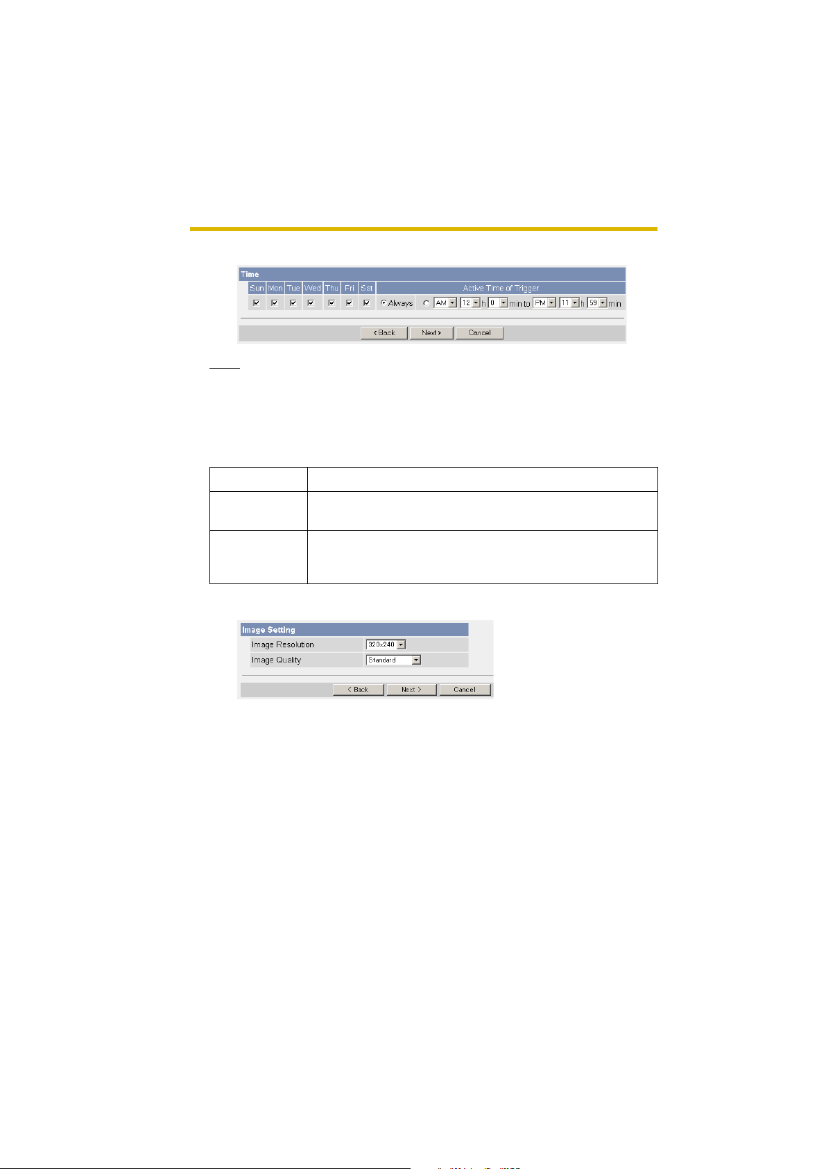
4. Set the time, and click [Next>].
Note
The timer works b y an internal cl oc k. Se t the date a nd time bef o re usi ng tim er
buffer/transfer (see page 40).
• Clicking [<Back] takes you back to the previous page.
• Clicking [Cancel ] takes you bac k to the Image Buffer/ T ransfe r page without
saving changes.
Setting Description
A day of the
week
Active Time of
Trigger
• Check the bo x to enable the da y . Cle ar the box to disab le it.
• Select the [Always] option when you do not specify the time
period. If you sp ecify the time period, sel ect the time period
option and set the time period.
5. Set the image settings, and click [Next>].
• Clicking [<Back] takes you back to the previous page.
• Clicking [Cancel ] takes you bac k to the Image Buffer/ T ransfe r page without
saving changes.
58
Page 59

Setting Description
Operating Instructions
Image
Resolution
Image Quality • Select the image quality.
• Select image re so luti on (64 0 x 48 0, 320 x 240 (default) or
160 x 120 pixels) to buffer or transfer.
[Favor Clarity] optimizes for good quality.
[Standard] offers standard quality.
[Favor Motion] optimizes for enhanced motion.
[Mobile Phone] is for a transfer to a mobile phone.
Note
640 x 480 pixels cannot be set for a transfer to a mobile
phone.
6. Set the image buffer frequencies, and click [Next>].
• Clicking [<Back] takes you back to the previous page.
• Clicking [Canc el] takes you bac k to the Image Buffer/Transfer page without
saving change s.
Setting Description
Image Buffer
Frequency
• Select the image buffer frequency to buffer or transfer the
image. (1 image per hour—15 images per second)
[For assistance, please call: 1-800-272-7033] 59
Page 60

Operating Instructions
7. Select the transfer method, and click [Next>].
• Clicking [<Back] takes you back to the previous page.
• Clicking [Cancel ] takes you bac k to the Image Buffer/ T ransfe r page without
saving changes.
Note
If you transfer image by E-mail or FTP, confirm that the default gateway and
DNS server addresses are assigned correctly (see page 30).
Setting Description
60
No Transfer, No
Memory
Overwrite
No Transfer,
Memory
Overwrite
FTP • The camera transfers the image to an FTP server (see
E-mail • The camera transfers the image by E-mail (see page 62).
• If the internal memory is full, the camera stops the buffer.
• If the internal memory is full, the camera deletes the old
images, and continues to buffer the image.
page 61).
Page 61

Operating Instructions
When you set [FTP] for Transfer Method
Select [FTP], and click [Next>]. The following page is displayed.
• Clicking [<Back] takes you back to the previous page.
• Clicking [Canc el] takes you bac k to the Image Buffer/Transfer page without
saving change s.
Setting Description
Server IP
Address or
Host Name
• If you set the server IP address, set 4 digits (0—255) and 3
periods such as "192.168.0.253". But "0.0.0.0" and
*1
"255.255.255.255" are not available. Or set a host name (1—
255 characters).
Port No. • Enter the number (1—65535). Usually set to 21.
*1
Login ID
Password
• If your ISP requires a login ID, set it (0—63 characters).
*1
• If your ISP requires a password, set it (0—63 characters).
Login Timing • Select the logi n timing to an FT P server. If you set [One Time]
during 1-minute transfer, the camera logs in to the server only
once, and can reduce the time to log in or log out.
Upload File
*1
Name
• Set the file name to save on an FTP server. Enter 1—234
characters. Entering "\" creates directories for a file. (E.g.
NetworkCamera\image.jpg)
Overwrite
setting
• Selecting [Overwr ite File] saves and overwrites the image on
the server. Selecting [Save as New File with Time Stamp]
saves the image attaching time stamps on the file name, and
the images are not overwritten.
Data
Transfer
• Select [Passive Mode] normally. If FTP does not work, select
[Active Mode] and check the operation.
Method
*1
But [Space], ["], ['], [&], [<] and [>] are not available.
[For assistance, please call: 1-800-272-7033] 61
Page 62
Operating Instructions
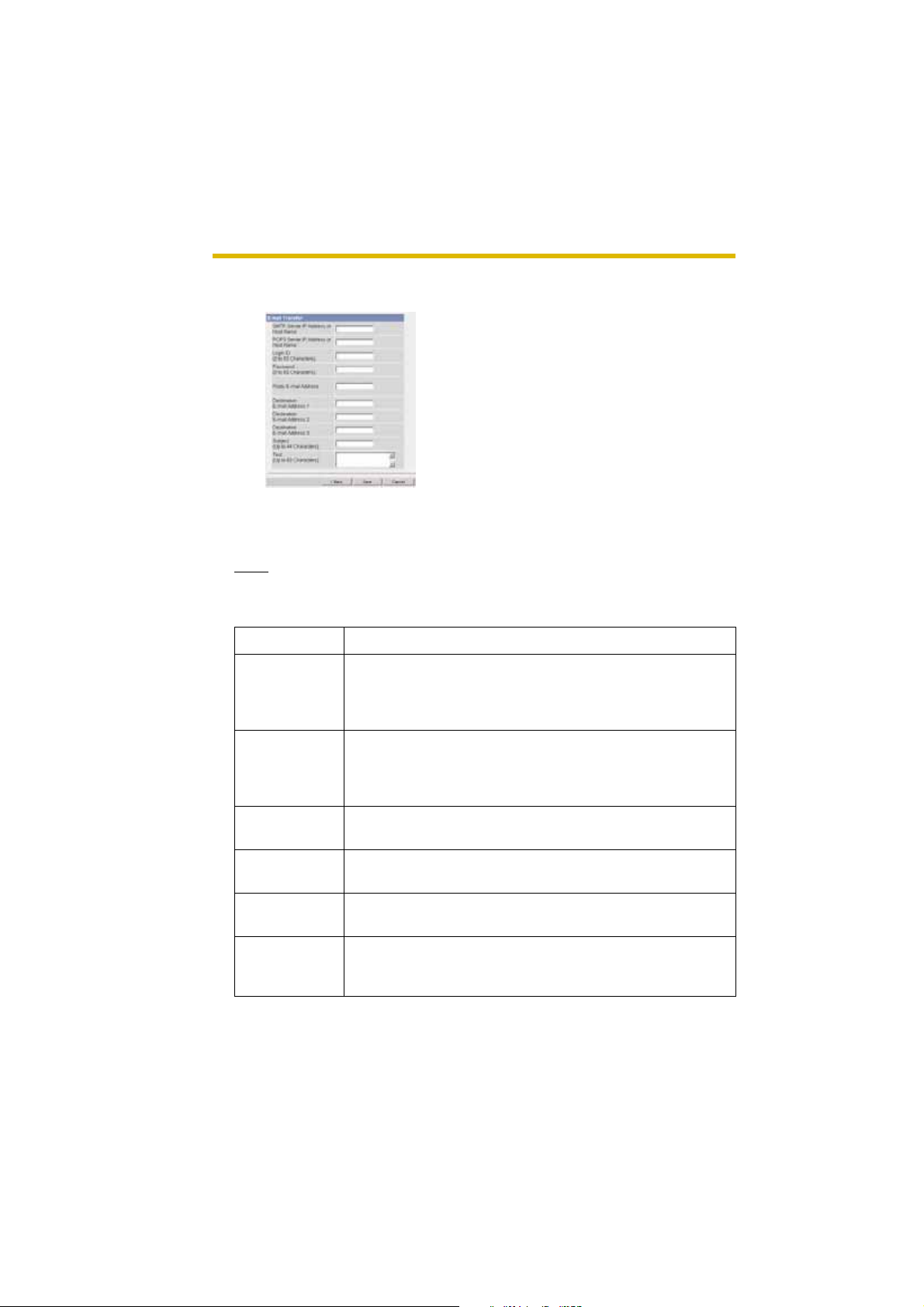
When you set [E-mail] for Transfer Method
Select [E-mail], and click [Next>]. The following page is displayed.
• Clicking [<Back] takes you back to the previous page.
• Clicking [Cancel ] takes you bac k to the Image Buffer/ T ransfe r page without
saving changes.
Note
The camera wo rks only with an SMTP (Simple Ma il Transfer Protocol) server.
It does not work with mail servers like "Hotmail
Setting Description
®
" using a web browser.
62
SMTP Server IP
Address or Host
Name
POP3 Server IP
Address or Host
Name
Login ID
Password
*1
*1
Reply E-mail
Address
*1
Destination Email Address
*1
1—3
• If you set the server IP address, set 4 digits (0—255) and
3 periods such as "192.168.0.253". But "0.0.0.0" and
"255.255.255.255" are not available. Or set a host name
(1—255 characters).
• If you set the server IP address, set 4 digits (0—255) and
3 periods such as "192.168.0.253". But "0.0.0.0" and
"255.255.255.255" are not available. Or set a host name
(1—255 characters).
• If your ISP requires a login ID to log in to a POP3 server,
set it (0—63 characters).
• If your ISP re quires a pa ss word to log in to a POP3 server,
set it (0—63 characters).
• Set the sender's E-mail address. We recommend you to
set the administrator's E-mail address.
• Set the destination E-mail address (up to 3).
Page 63

Operating Instructions
Setting Description
Subject • Enter a subject with ASCII characters (see page 107) or
characters in each language (0—44 characters f or a 1-byte
character and 0—22 characters for a 2 -byte character). But
["] is not available.
Text • Enter text with ASCII characters (see page 107) or
characters in each language (0—63 characters f or a 1-byte
character and 0—31 characters for a 2 -byte character). But
["] and [end-of-line] key are not available.
*1
But [Space], ["], ['], [&], [<] and [>] are not available.
8. Confirm the settings, and click [Save].
• New settings are saved. The buffered images are deleted.
• When finished, "Success!" is displayed.
9. Click [Go to Image Buffer/Transfer page].
• The Image Buffer/Transfer page is displayed.
Notes
• If you set a short interval to transfer image to a mobile phone, many Emails may be sent to it leading to a large phone bill. Therefore, we
recommend you to set a long interval. In an emergency situation, the Email transfer can be stopped by enabling privacy mode using a mobile
phone (see page 26).
• Buffered image s wi ll be del eted b y doi ng the following.
• Turning off the camera.
• Saving the settings of Image Buffer/Transfer or Date and Time.
• Executing [Restart], [Update Firmware] or [Reset to Factory Default].
• Clicking [Dele te Buffered Images] on the Image Buffer/T r a nsfer page
(see page 57).
[For assistance, please call: 1-800-272-7033] 63
Page 64

Operating Instructions
2.14 Buffering or Transferring Images by Sensor
The Image Buffer/Transfer page allows you to enable image buffer/transfer by Email or FTP.
1. Click [Buffer/Transfer] on the Setup page.
2. Click [No.] to enable buffer/transfer.
3. Check [Enable Image Buffer/Transfer], select [Sensor] for trigger, and click
[Next>].
• Click [Delete Buffered Images] to delete this buffered images.
• Click [Save] to save the settings. The buffered images are deleted.
• Clicking [Cancel ] takes you bac k to the Image Buffer/ T ransfe r page without
saving changes.
64
Setting Description
Enable Image
Buffer/Transfer
Trigger • Selecting [Timer] enable s the came ra to b uffe r/transf er the
• Check the box to enable the buffer/transfer. Clear the box
to disable it.
image by timer.
• Selecting [Sensor] enables the camera to buffer/transfer
the image by sensor.
Page 65

Operating Instructions
4. Set the time, and click [Next>].
Note
The timer works b y an internal clo c k. Set the d ate a nd tim e before using timer
buffer/transfer (see page 40).
• Clicking [<Back] takes you back to the previous page.
• Clicking [Canc el] takes you bac k to the Image Buffer/Transfer page without
saving change s.
Setting Description
A day of the
week
Active Time of
Trigger
• Check the bo x to enab le the da y. Clear the bo x to disa ble it.
• Select the [Alwa ys] option when y ou do not specify the time
period. If you spe cify the time period, sel ect the time period
option and set the time period.
• Selecting [Sensor] enables the camera to buffer/transfer
the image by sensor.
5. Set the Lens Position When Triggered setting, and click [Next>].
Note
If you enable the Lens Position When Triggered setting, buffer/transfer starts
after the camera turns to the sensor position.
• Clicking [<Back] takes you back to the previous page.
• Clicking [Canc el] takes you bac k to the Image Buffer/Transfer page without
saving change s.
[For assistance, please call: 1-800-272-7033] 65
Page 66

Operating Instructions
Setting Description
Lens Position
When Triggered
• Set [Move to sensor position] to move the lens to the
sensor position (see page 17) when the pyroelectric
infrared sensor detects temperature differences.
6. Set the image settings, and click [Next>].
• Clicking [<Back] takes you back to the previous page.
• Clicking [Cancel ] takes you bac k to the Image Buffer/ T ransfe r page without
saving changes.
Setting Description
Image
Resolution
Image Quality • Select the image quality.
• Select image resolu tion (640 x 480, 320 x 240 (defa ult ) or
160 x 120 pixels) to buffer or transfer.
[Favor Clarity] optimizes for good quality.
[Standard] offers standard quality.
[Favor Motion] optimizes for enhanced motion.
[Mobile Phone] is for a transfer to a mobile phone.
Note
640 x 480 pixels cannot be set for a transfer to a mobile
phone.
66
Page 67

Operating Instructions
7. Set the image buffer frequencies and non detection time, and click [Next>].
• Clicking [<Back] takes you back to the previous page.
• Clicking [Canc el] takes you bac k to the Image Buffer/Transfer page without
saving change s.
Setting Description
Enable Pretrigger Image
Buffer
Enable P o sttrigger Image
Buffer
• Check the bo x to enab le the setting. The ca mera b uffers or
transfers the image right before the pyroelectric infrared
sensor detects temperature differences.
• Set an interval, number of images to buffer and total
number. The buffered images may not match the total
number due to me mo ry capaci ty, image resolution, image
quality or what object you view.
• Check the bo x to enab le the setting. The ca mera b uffers or
transfers the image right after the pyroelectric infrared
sensor detects temperature differences.
• Set an interval, number of images to buffer and total
number. The buffered images may not match the total
number due to me mo ry capaci ty, image resolution, image
quality or what object you view.
[For assistance, please call: 1-800-272-7033] 67
Page 68

Operating Instructions
Setting Description
Non detection
time
• Set the length of time during which the sensor cannot be
triggered after saving images temporarily or transmitting
them. This function is recommend ed to use not to send too
many E-mails to a mobile phone.
Note
The internal memory cannot buffer images during Non
detection time. Because of this, images taken before
detection are not sa v ed in in ternal memo ry , and so cannot
be received. Depending on the settings for image buffer/
transfer, even if it is set to, for example, take "1 image per
second, and store 10 images, before detection", because
the images are not stor ed in internal memo ry , if the se nsor
detects something directly after the end of Non detection
time, the image s ma y not be saved. Ten seconds after the
end of Non detection time, images can be received as
specified in the settings.
68
Page 69

Operating Instructions
8. Select the transfer method, and click [Next>].
• Clicking [<Back] takes you back to the previous page.
• Clicking [Canc el] takes you bac k to the Image Buffer/Transfer page without
saving change s.
Note
If you transf e r image by E-mail or FTP, confirm that the default gateway and
DNS server addresses are assigned correctly (see page 30).
Setting Description
No Transfer , No
Memory
Overwrite
No Transfer,
Memory
Overwrite
FTP • The camera transfers the image to an FTP server (see
E-mail • The camera transfers the image by E-mail (see page 71).
• If the internal memory is full, the camera stops the buffer.
• If the internal memory is full, the camera deletes the old
images, and continues to buffer the image.
page 70).
[For assistance, please call: 1-800-272-7033] 69
Page 70

Operating Instructions
When you set [FTP] for Transfer Method
Select [FTP], and click [Next>]. The following page is displayed.
• Clicking [<Back] takes you back to the previous page.
• Clicking [Cancel ] takes you bac k to the Image Buffer/ T ransfe r page without
saving changes.
Setting Description
Server IP
Address or
Host Name
• If you set the server IP address, set 4 d i gits (0—255) and 3
periods such as "192.168.0.253". But "0.0.0.0" and
*1
"255.255.255.255" are not available. Or set a host name (1—
255 characters).
Port No. • Enter the number (1—65535). Usually set to 21.
*1
Login ID
Password
• If your ISP requires a login ID, set it (0—63 characters).
*1
• If your ISP requires a password, set it (0—63 characters).
Login Timing • Select the logi n timing to an FTP server. If you set [One Time]
during 1-minute transfer, the camera logs in to the server only
once, and can reduce the time to log in or log out.
Upload File
*1
Name
• Set the file name to save on an FTP server. Enter 1—234
characters. Entering "\" creates directories for a file. (E.g.
NetworkCamera\image.jpg)
Overwrite
setting
• Selecting [Overwr i te File] saves and overwrites the image on
the server. Selecting [Save as New File with Time Stamp]
saves the image attaching time stamps on the file name, and
the images are not overwritten.
Data
Transfer
• Select [Passive Mode] normally. If FTP does not work, select
[Active Mode] and check the operation.
Method
*1
But [Space], ["], ['], [&], [<] and [>] are not available.
70
Page 71

Operating Instructions
When you set [E-mail] for Transfer Method
Select [E-mail], and click [Next>]. The following page is displayed.
• Clicking [<Back] takes you back to the previous page.
• Clicking [Canc el] takes you bac k to the Image Buffer/Transfer page without
saving change s.
Note
The camera works only with an SMTP (Sim ple Mai l Transfer Protocol) server .
It does not work with mail servers like "Hotmail" using a web browser.
Setting Description
SMTP Server IP
Address or Host
Name
POP3 Server IP
Address or Host
Name
Login ID
Password
*1
*1
Reply E-mail
Address
*1
Destination Email Address
*1
1—3
• If you set the server IP address, set 4 digits (0—255) and
3 periods such as "192.168.0.253". But "0.0.0.0" and
"255.255.255.255" are not available. Or set a host name
(1—255 characters).
• If you set the server IP address, set 4 digits (0—255) and
3 periods such as "192.168.0.253". But "0.0.0.0" and
"255.255.255.255" are not available. Or set a host name
(1—255 characters).
• If your ISP requires a login ID to log in to a POP3 server,
set it (0—63 characters).
• If your ISP requires a pass wo rd to log in to a POP3 server ,
set it (0—63 characters).
• Set the sender's E-mail address. We recommend you to
set the administrator's E-mail address.
• Set the destination E-mail add res s (up to 3).
[For assistance, please call: 1-800-272-7033] 71
Page 72

Operating Instructions
Setting Description
Subject • Enter a subject with ASCII characters (see page 107) or
characters in each lan guage (0—44 characters f or a 1-byte
character and 0—22 c haracters for a 2-b yte character). But
["] is not available.
Text • Enter text with ASCII characters (see page 107) or
characters in each lan guage (0—63 characters f or a 1-byte
character and 0—31 c haracters for a 2-b yte character). But
["] and [end-of-line] key are not available.
*1
But [Space], ["], ['], [&], [<] and [>] are not available.
9. After you confirm the setting s and click [Ne xt>], set E-mail notifi cation and clic k
[Next>].
• If you select [Enable], the E-mail Notification When Triggered page is
displaye d. Enter the setting s seeing page 71 and pa ge 72. When finishe d,
click [Next>] and go to step 10.
72
Setting Description
Disable • The camera does not send an E-mail notification when
buffering or transferring image.
Enable • The camera sends an E-mail notification (up to 3
destinations) when buffering or transferring image.
10.Click [Save] after confirming the settings.
• New settings are saved. The buffered images are deleted.
• When finished, "Success!" is displayed.
Page 73

Operating Instructions
11.Click [Go to Image Buffer/Transfer page].
• The Image Buffer/Transfer page is displayed.
Notes
• If you set a short interval to transfer image to a mobile phone, many Emails may be sent to it leading to a large phone bill. Therefore, we
recommend you to set a long interval. In an emergency situation, the Email transfer can be stopped by enabling privacy mode using a mobile
phone (see page 26).
• Sensor transf er stops its ope rations unti l the camera fin ishes all tra nsfers .
For example, if the camera transfers 3 images per minute and 6 images in
total with setting 1 minute of non detection time, the sens or will be in the
following operation.
120 seconds
1 minute
1st 2nd 3rd 4th 5th 6th
Detectable UndetectableUndetectable
Non detection
time
Detectable
A heat change occurs.
• Buffered image s wi ll be del eted b y doi ng the following.
• Turning off the camera.
• Saving the settings of Image Buffer/Transfer or Date and Time.
• Executing [Restart], [Update Firmware] or [Reset to Factory Default].
• Clicking [Dele te Buffered Images] on the Image Buffer/T r a nsfer page
(see page 64).
[For assistance, please call: 1-800-272-7033] 73
Page 74
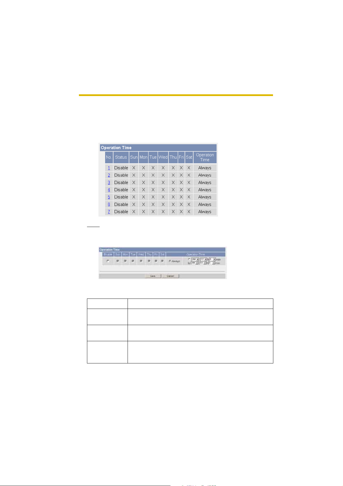
Operating Instructions
2.15 Specifying Operation Time
The Operation Ti me page allo ws you to li mit the oper ation time. The camera im age
turns to a gray screen outside the operation time.
1. Click [Operation Time] on the Setup page.
2. Click [No.] to set the operation time.
Note
If No. 1—7 are disabled, the camera can always be operated.
3. Check [Enable], set the time, and click [Save]
74
• Clicking [Cancel] takes you back to the previous page without saving
changes.
Setting Description
Enable • Check the box to enable the setting. Clear the box to
disable it.
A day of the
week
Operation Time • Select the [Always] option when you do not specify the time
• Check the bo x to enable the da y . Cle ar the box to disab le it.
period. If you sp ecify the time period, sel ect the time period
option and set the time period.
Page 75

Operating Instructions
4. Click [Save] when finished.
• New settings are saved.
• The Operation Time page is displayed.
About Operation Time
In the operation time settings, the enabled settings take priority over the disabled
settings. Therefore, if Monday or Tuesday is disabled in a setting but enabled in
other settings, the camera can be operated on both Monday and Tuesday.
[For assistance, please call: 1-800-272-7033] 75
Page 76
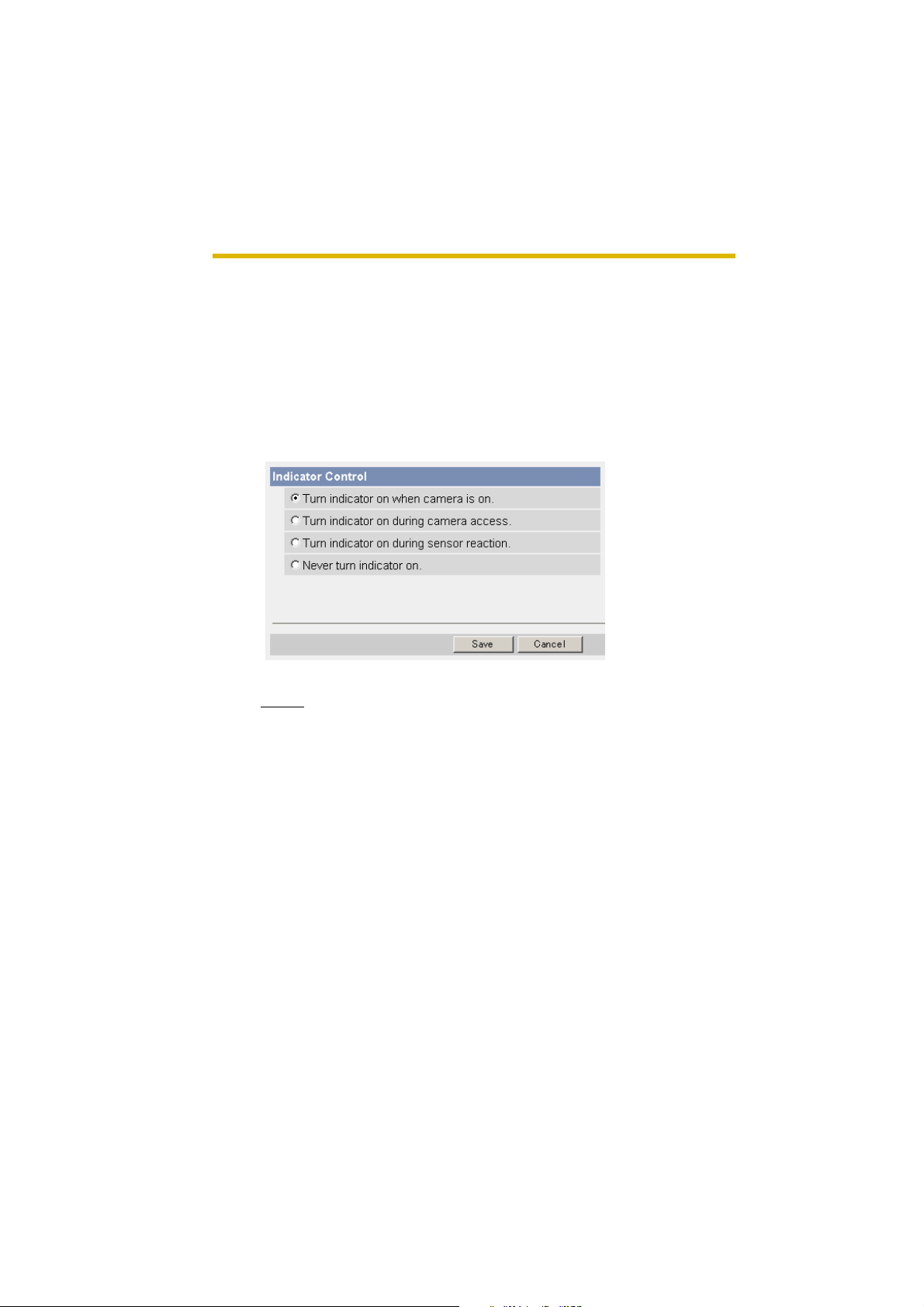
Operating Instructions
2.16 Changing Indicator Display
The Indicator Control page allows you to select Indicator operation. Indicator has
four options.
•Always on
• Turn the indicator on when the camera is accessed.
• Turn the indicator on during sensor reaction.
•Always off
1. Click [Indicator Control] on the Setup page.
2. Select indicator option.
• Clicking [Cancel] cancels your settings without saving changes.
76
Notes
• See page 7 in the Installation/Troubleshooting for indicator display.
• Selecting [Never turn indicator on] keeps indicator always off.
3. Click [Save] when finished.
• New settings are saved.
• When finished, "Success!" is displayed.
4. Click [Go to Indicator Control page].
• The Indicator Control page is displayed.
Page 77

Operating Instructions
2.17 Enabling Privacy Mode
Pressing the priv acy button tu rns the camera int o privacy m ode. You can keep your
privacy in privacy mode. In this case, the camera operation stops, and the image
transfer by timer or sensor (see page 57 or page 64) is also stopped. The indicator
turns red, and viewers see a gray screen. Privacy mode can be controlled from a
mobile phone (see page 25) or a PC.
1. Click [Privacy Mode] on the Setup page.
2. Click [Save] when finished.
• Selecting [Enab le ] and cli cking [Save] turn the camera into privacy mode.
Setting Description
Privacy Button • Clearing the Enable box di sables the privacy button on the
front of the camera.
Privacy Mode • Selecting [Enable] and clicking [Sav e] turn the cam era int o
privacy mode.
Notes
• To turn the camera into normal oper ation , press the priv ac y b utton on the
front of the camera (see page 7 in the Installation/Troubleshooting) during
privacy mode. Or click [Disable Privacy Mode] after you log in as an
administrator.
• If you log in as an administrator, you can disable privacy mode from your
mobile phone (see page 25).
[For assistance, please call: 1-800-272-7033] 77
Page 78

Operating Instructions
(
(
(
(
(
(
(
3 Camera Maintenance
3.1 Maintenance page
15)
16)
17)
18)
19)
20)
21)
Maintenance
(15) Status Displays the camera settings and status (see page 79).
(16) Wireless Status Displays wireless information (see page 79).
(17) Restart Restarts the camera (see page 80).
(18) Update Firmware Updates the camera firmware (see page 81).
(19) Save Settings Creates a configuration file (see page 84).
(20) Load Settings Loads settings from a configuration file (see page 85).
(21) Reset to Factory
Default
78
Resets the camera to its default settings (see page 86).
Page 79

Operating Instructions
3.1.1 Confirming the Status
The Status page allows you to check the status of the camera. The status
information provides support for troubleshooting.
Clicking [Status] displays the following page.
Note
See Panasonic Network Camera support website at http://panasonic.co.jp/
pcc/products/en/netwkcam/ for details about status information.
3.1.2 Confirming the Wireless Status
The Wireless Status page allows you to check the wireless information. The
wireless status information provides support for troubleshooting regarding wireless
connection.
Clicking [Wireless Status] displays the following page.
[For assistance, please call: 1-800-272-7033] 79
Page 80

Operating Instructions
3.1.3 Restarting the Camera
The camera restarts by disconne cti ng th e plu g of the AC cord from the outlet and
reconnecting it again. The camera can also be restarted on the Restart page.
Note
When the camera restarts, the buffered images will be deleted.
1. Click [Restart] on the Maintenance page.
2. Click [Restart].
• Restarting takes about 90 seconds. The Top page is displayed when
finished.
80
Page 81

Operating Instructions
3.1.4 Updating the Camera Firmware
The Update Firmware page al lows you to update the camera firmware . If th e new
firmware is available, install it into the camera.
Notes
• Do not turn off the power during firmware update.
• All buffered images will be deleted after the firmware update.
• The firmware version is displayed on the Top page and the Status page.
1. Download the new firmware on the Panasonic Network Camera support
website at http://panasonic.co.jp/pcc/products/en/netwkcam/, an d save it
on your PC.
2. Click [Update Firmware] on the Maintenance page.
3. Click [Update Fi rmware].
• The camera restarts.
[For assistance, please call: 1-800-272-7033] 81
Page 82

Operating Instructions
• The Update page is displayed in about 90 seconds.
4. Click [Browse...].
• A dialog box is displayed to select the firmware.
5. Select the firmware (including directory information) and click [Open].
• The firmware file name is displayed.
6. Confirm the firmware file name, and click [Update Firmware].
• Clicking [Canc el] tak es y ou ba ck to the Top page without firmware update.
• The next message is displayed during update.
• The camera restarts automatically after update.
82
• The Top page is displayed in about 90 seconds.
Page 83

Operating Instructions
7. Confirm that the version number on the Top page is updated.
Updated version
• If the version number is updated, the firmware update is complete.
[For assistance, please call: 1-800-272-7033] 83
Page 84

Operating Instructions
3.1.5 Creating Configuration File
A configuration file can be saved on your PC. You can load the camera settings
from the configuration file on the Load Settings page (see page 85).
1. Click [Save Settings] on the Maintenance page.
2. Click [Save].
3. Click [Save] on the File Download dialog box.
4. Specify the location, and click [Save] on the Save As dialog box.
• The configuration file is saved in the location.
84
Notes
• The file exten sion (.d at) can not be ch anged . If y ou cha nge it, the setti ngs
cannot be loaded.
• If you try to updatin g the ca mera, c reate a c onfigur ation file after updating
the firmware. If there is a firmware version difference betw een the camera
that you create a conf iguration file from and the camera that yo u try to load
settings to, the se ttin gs may not be loaded to the camera.
Page 85

Operating Instructions
3.1.6 Loading Settings from a Configuration File
The settings can be loaded from a configuration file. If you reset the camera to
factory default, the camera can load its settings from the configuration file.
Notes
• The configurati on file has network set tings. Wh en the setti ngs are load ed,
the network settings are also loaded as they were saved.
• If there is a firmware version difference between the camera that you
create a config uration file from and the camera that you try to load settings
to, the settings may not be loaded to the camera. Save settings after
updating the firmware.
1. Click [Load Settings] on the Maintenance page.
2. Click [Browse...].
3. Select the configuration file on the Choose file dialog box, and click [Open].
• The file name is displayed in the data field.
4. Confirm the file name, and click [Load].
5. Click [Restart].
• The camera restarts, and the Top page is displayed.
[For assistance, please call: 1-800-272-7033] 85
Page 86

Operating Instructions
3.1.7 Resetting the Camera to Factory Default
All camera settings are reset to factory default directly after the Execute button is
clicked.
1. Click [Reset to Factory Default] on the Maintenance page.
2. Click [Execute].
• The indicator blinks orange, and then turns off for 10 seconds.
• All camera settin gs (user na me, pa ss word, IP a ddress , subnet mas k etc.)
are reset to factory default.
• If the camera is reset to factory default, the networ k connection mode
changes to [Aut omatic Setup]. Reconfig ure the camera seein g the Getting
Started.
Notes
• The internal clock will not be reset, but the time format will return to AM/
PM mode (see page 40). Se t it again.
• See page 90—page 97 for default settings.
• Pressing the F ACT ORY DEF A ULT RESET button resets the camer a to the
factory default (see page 89).
• All buffered images are deleted when resetting the camera to factory
default.
• The reset operation takes about 1 minute.
• Do not turn off the camera during the reset operation.
86
Page 87

Operating Instructions
3.2 Support page
(22)
(23)
(24)
(25)
Support
(22) Help Displays the Help page (see page 87).
(23) Wireless Help Displays the Wireless Help page (see page 88).
(24) Product
Information
(25) Support
Information
Displays product information website (see page 88).
Displays support information website (see page 88).
3.2.1 Seeing Help page
The Help page displays explanations for each feature about the following 1. to 6.
items.
Clicking [Help] on the Support page displays the next page.
[For assistance, please call: 1-800-272-7033] 87
Page 88

Operating Instructions
3.2.2 Seeing Wireless Help page
The Wireless Help pa ge displays explanations for each feature about Wireless
Basic configuration, Wireless Cipher configuration and Wireless Status.
Clicking [Wireless Help] on the Support page displays the next page.
Note
[Wireless Help] is displayed only when logging in as an administrator.
3.2.3 Seeing Product Information
You can see product information on the Panasonic Network Camera support
website.
Clicking [Product Information] on the Support page displays the URL, click it.
Note
If the camera is not connected to the Internet, the web site cannot be dis played .
3.2.4 Seeing Support Information
You can see support information on the Panasonic Network Camera support
website.
Clicking [Support Information] on the Support page displays the URL, click it.
88
Note
If the camera is not connected to the Internet, the web site cannot be dis played .
Page 89

Operating Instructions
3.3 FACTORY DEFAULT RESET Button
The camera has a FACTORY DEFAULT RESET button on the bottom.
Press the button
with a pointed
object.
Pressing the FACTORY DEFAULT RESET button resets the camera to factory
default. If you lose your user name and password, use this button to reset the
camera.
• Press the F A CTORY DEF AUL T RESET butto n f or 1 second whe n the camera
is on.
• The indicator blinks orange, and then turns off for 10 seconds.
• Do not turn off the camera until the indicator lights green.
Notes
• The internal clock will not be reset, but the time format will return to AM/
PM mode (see page 40). Set it again.
• See page 90—page 97 for default settings.
• All buffered images are deleted when resetting the camera to factory
default.
• The reset operation takes about 1 minute.
[For assistance, please call: 1-800-272-7033] 89
Page 90

Operating Instructions
3.4 Default Setting List
Basic
Items Default Required Notes
Network Connection Mode Automat ic
Setup
Allow Access from the
Internet (Automatic
Setup only)
Network Configuration
from Setup Program
(Static/DHCP only)
Port No.
(Static/DHCP only)
IP address
(Static only)
Subnet Mask
(Static only)
Host Name
(DHCP only)
Default Gateway
(Static/DHCP only)
DNS Server 1
DNS Server 2
(Static/DHCP only)
No - -
Enable - -
80 - 20, 21, 25 and 110
192.168.0.
253
255.255.
255.0
[Blank] When
[Blank] When using
[Blank] When using
- Automatic Setup/
Static/DHCP
is not available. *2
When
setting Static
When
setting Static
0—63 characters
setting
DHCP (Not
always
required)
Gateway
DNS
*4
*1
*1
*1
*1
90
Max. Bandwidth Usage
(Mbps)
Connection Type Auto
Unlimited - 0.1, 0.2, 0.3, 0.5, 1
Negotiation
or Unlimited
--
Page 91

Operating Instructions
Items Default Required Notes
Wireless Communication mode 802.11b/g - -
(Channel) Auto - SSID BLC30AXXX
X
-Up to 32
characters, signs
or numbers
(Speed) Auto - Encryption (WEP) No
--
encryption
Authenticati on Open System - WEPKey 1—4 ASCII 13
--
Characters
128 bit
UPnP Auto Port Forwarding Disable - -
Display Shortcut Icon in
Enable - -
My Network Places
Viewnet
Enable No check - -
cam.com
Date and
Time
Time Setting AM/PM - Automatic Time
Adjustment
No check When using
NTP
Time Zone GMT -05:00 - Adjust Clock for
No check - -
Daylight Saving Time
-
Start Day Apr,
First Sunday,
2 AM
End Day Oct,
Last Sunday,
2 AM
[For assistance, please call: 1-800-272-7033] 91
--
--
Page 92

Operating Instructions
Items Default Required Notes
Camera Camera Name Network
Camera
White Balance Auto - Auto/Fixed Indoor/
AC Power Source
60 Hz - 50 Hz, 60 Hz
Frequency
Pan Range (Minimum) -50 degrees - -50—+50 degrees
(Home Position) 0 degrees - -50—+50 degrees
(Maximum) +50 degrees - -50—+50 degrees
Tilt Range (Minimum) -40 degrees - -40—+10 degrees
(Home Position) 0 degrees - -40—+10 degrees
(Maximum) +10 degrees - -40—+10 degrees
Required 1—15 characters
*6
Fixed Fluorescent
(White)/Fixed
Fluorescent
(Daylight)/Fixed
Outdoor/Hold
92
Page 93

Account
Operating Instructions
Items Default Required Notes
Security:
Administrator
General
Authentication
Do not permit
access from
--
guest users
User Name [Blank] When setting
administrator
Password [Blank] When setting
administrator
Retype
Password
[Blank] When setting
administrator
6—15 characters
*3
6—15 characters
*3
6—15 characters
*3
General User User ID List [B lank] - -
User Name [Blank] When setting
general user
Password [Blank] When setting
general user
Retype
Password
[Blank] When setting
general user
6—15 characters
*3
6—15 characters
*3
6—15 characters
*3
Access Level Level 3 - -
[For assistance, please call: 1-800-272-7033] 93
Page 94

Operating Instructions
Advanced
Items Default Required Notes
Image
Display
Single Camera Image
Resolution
Single Camera Image
Quality
320 x 240 - 320 x 240 or 640
x 480
Standard - Favor Clarity,
Standard or
Favor Motion
Single Camera
Refresh Interval
Multi-Camera Image
Resolution
Multi-Camera Image
Quality
Motion - 3, 5, 10, 30, 60
(s) or Motion
320 x 240 - 160 x 120 or 320
x 240
Standard - Favor Clarity,
Standard or
Favor Motion
Multi-Camera R efresh
Interval
Motion When
reducing
3, 5, 10, 30, 60
(s) or Motion
traffic
Limit Continuous
Motion JPEG
Still Image Refresh
Interval
Unlimited When
reducing
traffic
10, 30 (s), 1, 5,
10, 30, 60 (min)
or Unlimited
30 s - 3, 5, 10, 30 or 60
(s)
Language English - English/
Japanese/
French/German/
Italian/Spanish/
Simplified
Chinese/Russian
94
Page 95

Operating Instructions
Items Default Required Notes
MultiCamera
Multi-Camera [Blank] - Display Checked When setting
Multi-Camera
IP Address or Host
Name
[Blank] When setting
Multi-Camera
IP address*1
Host name*5 is
1—255
characters.
Port No. [Blank] When setting
Multi-Camera
20, 21, 25 an d
110 are not
available. *2
Camera Name [Blank] When setting
Multi-Camera
Change Camera
Order
From No.1 to
No.1
When
changing
1—15 characters
*7
From No.1—12
to No.1—12
camera order
-
[For assistance, please call: 1-800-272-7033] 95
Page 96

Operating Instructions
Items Default Required Notes
Buffer/
Transfer
Status Off - Trigger Timer - Timer, Sensor
Active Time of Trigger Always - Lens Position When
Triggered
Do not move - Do not move,
Move to sensor
position
Image Resolution 320 x 240 - 160 x 120,
320 x 240,
640 x 480
Image Quality Standard - Favor Clarity,
Standard,
Favor Motion
Image Buffer
Frequency
Every 1 s,
buffer 1 image
- Every 1 (s/min/
h), buffer 1—15
images
Non detection time No
appointment
Transfer Method No Transfer,
When
selecting
sensor
No appointment,
10, 30 (s), 1, 3, 5,
10 (min)
--
No Memory
Overwrite
Notify - - -
96
Operation
Time
Indicator
Control
Privacy
Mode
Operation Time Alwa ys - -
Indicator Control Turn indica tor
--
on when
camera is on
Privacy Button Checked - Privacy Mode Disable - -
Page 97

Preset Buttons
Items Default Required Notes
Operating Instructions
Preset
Buttons
Preset 1 UpperLeft - Preset 2 UpperRight - Preset 3 LowerLeft - Preset 4 LowerRight - -
*1 Set 4 digits (0—255) and 3 periods such as "192.168.0.253" . But "0.0.0.0" and
"255.255.255.255" are not available.
*2 Set the number of 1—65535.
*3 Enter ASCII characters for the host name (see page 107). But [Spa ce], ["], ['],
[&], [<], [>] and [:] are not available.
*4 Enter ASCII characters for the host name (see page 107). But [Spa ce], ["], ['],
[&], [<], and [>] are not available.
*5 Enter ASCII characters for the host name (see page 107). But [Spa ce], ["], ['],
[#], [&], [%], [=], [+], [?], [<], and [>] are not availab l e .
*6 Enter ASCII characters (see page 107) or charac ters in each language (1—15
characters for a 1-byte character and 1—7 ch aracters for a 2-byte char a cte r).
But [Space], ["], ['], [&], [<], and [>] are not available.
*7 Enter ASCII characters (see page 107) or charac ters in each language (1—15
characters for a 1-byte character and 1—7 ch aracters for a 2-byte char a cte r).
But [Space], ["], ['], [#], [&], [%], [=], [+], [?], [<], and [>] are not available.
[For assistance, please call: 1-800-272-7033] 97
Page 98

Operating Instructions
3.5 Cleaning
Clean the camera after the camera is turned off.
3.5.1 Cleaning the Main Unit
Clean the unit with a dry and soft cloth.
Notes
• Do not use alcohol, polishing powder, cleanser, benzine, thinner, wax,
petroleum products or hot water to wipe the camer a. Also av oid pesticid e,
glass cleaner or hair s pray. Th e y may cause change in the sha pe or c olor.
• Do not apply pressure to the pan/tilt portion of the camera. Any forced
movement can damage the internal mechanism.
• If the pyroelectric infrared sensor has dust on it, it may not detect
temperature differences. Keep the pyroelectric infrared sensor clean.
3.5.2 Cleaning the Lens
If the lens has dust on it, the image may be unclear or out of focus.
Note
Do not touch the lens directly. Fingerprints may cause an unclear image.
98
Page 99

Operating Instructions
3.6 Setting an IP Address on Your PC
Your PC's IP address can be assigned by the following procedures.
1. Display the TCP/IP Properties window.
• The steps are differe nt depe nding on your OS. The steps are shown
below.
OS Steps
Windows XP [Start] ( [Settings]) [Control Panel] [Network and
Internet Connections] [Network Connections] [Local Area
Connection] in use [Properties] Select Internet Protocol
[TCP/IP] [Properties] [Use the following IP address]
Windows 2000 [Start] [Settings] [Control Panel] [Network and Dial-up
Connections] [Local Area Connection] in use
[Properties] Select Internet Protocol [TCP/IP]
[Properties] [Use the following IP address]
Windows Me,
Windows 98SE
• When using Windows XP and Windows 2000, log in as an administrator
to access the TCP/IP Properties window.
[Start] [Settings] [Control Panel] [Network] Select
[TCP/IP] with adaptor in use [Properties] [IP Address]
[Specify an IP address]
2. Enter IP address and subnet mask.
3. Click [OK].
• In Windows Me or W indows 98SE, the PC needs to be restarted to enab le
the settings.
Local IP Address
Local IP address is the network ID that is not used on the Internet. They are
classified into Clas s A, Clas s B an d C lass C, as shown below. Set the IP address
in the range of the number specified in the class corresponding to your local
network scale.
Class Subnet Mask Local IP Address
Class A 255. 0. 0. 0 10. 0. 0. 1 — 10. 255. 255. 254
Class B 255. 255. 0. 0 172. 16. 0. 1 — 172. 31. 255. 254
Class C 255. 255. 255. 0 192. 168. 0. 1 — 192. 168. 0. 254
[For assistance, please call: 1-800-272-7033] 99
Page 100

Operating Instructions
3.7 Using Setup Program
The Setup Program can be used for the following purposes.
• Finding the IP address and port number of the camera connected to your
network.
• Setting up the camera automatically.
• Setting up the camera manually to a Static or a DHCP setting.
• Displaying the Setup page.
Finding the camera
1.
Connect the Ethernet cable to the camera following the Getting Started.
• If the Network Camera Setup window does not appear, click "setup.exe"
on the Setup CD-ROM.
2. Insert the Setup CD-ROM into the CD-ROM drive of your PC.
• If the Network Camera Setup window does not appear, click "setup.exe"
on the Setup CD-ROM.
3. Click [Camera Setup].
Displays version information about this
program.
Sets up the camera.
Displays the camera manuals.
If your PC does not have Adobe® Acrobat
Reader, install it from the Adobe Reader
website.
Closes the Setup Program.
®
100
• You can find the camera IP address and port number by looking up the
MAC address of your camera.
MAC
Address
IP
Address
Port
No.
Camera
Status
Camera
List window
 Loading...