

Page 1

Installation/Troubleshooting
Network Camera
Model No.
How to Use This Documentation
The camera includes the following 4 manual types.
• Installation/Troubleshooting (This manual)
This manual has important information you will need to understand before
installing the camera and troubleshooting tips.
• Getting Started
Getting Started provides explanations for the initial configuration and
accessories included with the camera. The Getting Started helps you to easily
configure the camera.
• Operating Instructions (Included on the Setup CD-ROM)
Operating Instructions explains about operations, settings, features and the
cleaning method when using the camera.
• IMPORTANT SAFETY INSTRUCTIONS
Basic safety precautions are described to use the camera.
BL-C30
Please read this manual before using and save this manual for future
reference.
Page 2

Installation/Troubleshooting
Abbreviations
• UPnP is the abbreviation for Universal Plug and Play.
• "Network Camera" is called "Camera" in this Installation/Troubleshooting.
Trademarks
• Microsoft, Windows, and ActiveX are either registered trademarks or
trademarks of Microsoft Corporation in the United States and/or other
countries.
• Screen shots reprinted with permission from Microsoft Corporation.
• All other trademarks identified herein are the property of their respective
owners.
2
Page 3

Installation/Troubleshooting
Table of Contents
1 Before Using ..................................................................4
1.1 IMPORTANT SAFETY INSTRUCTIONS........................................ 4
1.1.1 For European Union (EU).......................................................................... 6
1.1.2 User Name and Password Protection........................................................ 7
1.1.3 Video Recording Notice............................................................................. 7
1.2 Camera Feature Locations............................................................. 8
1.2.1 Front View.................................................................................................. 8
1.2.2 Bottom View .............................................................................................. 9
1.2.3 Rear View.................................................................................................. 9
1.3 Viewnetcam.com Service............................................................. 10
1.4 Connecting the Camera to a Router Supporting UPnP™ ............ 12
1.5 Connecting the Camera to a Router Not Supporting UPnP™ ..... 13
1.6 Setting Up the Camera Using the MAC Address on the Setup
Program ....................................................................................... 14
2 Troubleshooting ..........................................................19
2.1 About Indicator Display ................................................................ 19
2.2 About Camera Setup.................................................................... 21
2.3 About Wireless Communication ................................................... 24
2.4 About Camera Image and Page Display...................................... 25
2.5 About Privacy Mode ..................................................................... 30
2.6 About Pyroelectric Infrared Sensor .............................................. 31
2.7 About Operation Bar .................................................................... 33
2.8 About Image Buffer/Transfer ........................................................ 34
2.9 About Other Features................................................................... 35
3
Page 4

Installation/Troubleshooting
1 Before Using
1.1 IMPORTANT SAFETY INSTRUCTIONS
When using this unit, basic safety precautions should always be followed to reduce
the risk of fire, electric shock, or personal injury.
1. Read and understand all instructions.
2. Keep these instructions.
3. Heed all warnings.
4. Follow all instructions.
5. After taking away the dust on the lens, wipe the lens with a cotton bud.
6. Do not install near any heat sources such as radiators, heat registers, stoves,
or other devices (including amplifiers) that produce heat.
7. Protect the AC adaptor cord and AC cord from being walked on or pinched
particularly at plugs, convenience receptacles, and the point where they exit
from the unit.
8. The AC cord is used as the main disconnect device, ensure that the socket-
outlet is located/installed near the equipment and is easily accessible.
9. Do not touch the unit, AC adaptor, AC adaptor cord or AC cord during lightning
storms.
10. Unplug the unit when unused for long periods of time.
11. Refer all servicing to qualified service personnel. Servicing is required when
the unit has been damaged in any way, such as the AC adaptor cord, AC cord
or plug is damaged, the unit does not operate normally, or has been dropped.
12. Prolonged exposure to direct sunlight or halogen light may damage CMOS
sensor.
13. The camera is intended for indoor use only. Please check local regulations as
outdoor use of the wireless feature is restricted in some countries/areas.
SAVE THESE INSTRUCTIONS
4
Page 5

Network Camera Memo
Attach your purchase receipt here.
For your future reference
Date of purchase
Installation/Troubleshooting
Serial Number
(Found on the bottom side of the main unit)
Name and address of dealer
MAC Address
(Found on the bottom side of the main unit)
Environment:
Do not install the camera where the temperature is less than 5 °C or greater than
+40 °C. Allow 10 cm clearance around the unit for proper ventilation. Avoid
excessive smoke, dust, mechanical vibration, shock, or direct sunlight.
Routine care:
Wipe the unit with a soft cloth. Do not use benzine, thinner, or any abrasive powder.
When you leave the unit unused for a long period of time, unplug the AC cord from
the outlet.
If you have any problems:
Consult an authorized Network Camera dealer.
Caution
• This equipment must be installed and operated in accordance with provided
instructions and a minimum 20 cm spacing must be provided between antenna
and all person's body (excluding extremities of hands, wrist and feet) during
wireless modes of operation.
• This transmitter must not be co-located or operated in conjunction with any
other antenna or transmitter.
• Medical
Consult the manufacturer of any personal medical devices, such as
pacemakers, to determine if they are adequately shielded from external RF
(radio frequency) energy. (The unit operates in the frequency range of 2.412
GHz to 2.472 GHz, and the power output level is 0.1 watts.) Do not use the unit
in health care facilities if any regulations posted in the area instruct you not to
do so. Hospitals or health care facilities may be using equipment that could be
sensitive to external RF (radio frequency) energy.
• Any changes or modifications not expressly approved by the party responsible
for compliance could void the user's authority to operate this device.
No responsibility will be taken by our company with respect to consequences
resulting from the use, damage or both of the camera.
5
Page 6

Installation/Troubleshooting
1.1.1 For European Union (EU)
Panasonic Communications Co., Ltd., declares that this equipment is in
compliance with the essential requirements and other relevant provisions of Radio
& Telecommunications Terminal Equipment (R&TTE) Directive 1999/5/EC.
Declarations of Conformity for the relevant Panasonic products described in this
manual are available for download by visiting:
http://www.doc.panasonic.de
Contact:
Panasonic Services Europe GmbH
Panasonic Testing Centre
Winsbergring 15, 22525 Hamburg, F.R. Germany
0682
1999/5/EC
English This 2.4 GHz Wireless LAN equipment is intended for use in the
following countries in the EU: the United Kingdom, Germany,
Spain, France, Italy, Belgium, Denmark, Sweden, Finland,
Netherlands, Switzerland, and Greece.
Finnish Tämä 2,4 GHz:n langaton lähiverkkolaite on tarkoitettu
käytettäväksi seuraavissa EU-maissa: Iso-Britannia, Saksa,
Espanja, Ranska, Italia, Belgia, Tanska, Ruotsi, Suomi,
Alankomaat, Sveitsi ja Kreikka.
Dutch Deze draadloze LAN-apparatuur (2,4 GHz) is bedoeld voor gebruik
in de volgende EU-landen: Verenigd Koninkrijk, Duitsland, Spanje,
Frankrijk, Italië, België, Denemarken, Zweden, Finland,
Nederland, Zwitserland en Griekenland.
French Cet équipement LAN sans fil de 2,4 GHz a été conçu pour être
utilisé dans les pays suivants de la Communauté Européenne:
Royaume-Uni, Allemagne, Espagne, France, Italie, Belgique,
Danemark, Suède, Finlande, Pays-Bas, Suisse et Grèce.
Swedish Den här trådlösa LAN-utrustningen på 2,4 GHz är avsedd för
användning i följande EU-länder: Storbritannien, Tyskland,
Spanien, Frankrike, Italien, Belgien, Danmark, Sverige, Finland,
Nederländerna, Schweiz och Grekland.
Danish Dette 2,4 GHz trådløse LAN-udstyr er beregnet til brug i følgende
EU-lande: Storbritannien, Tyskland, Spanien, Frankrig, Italien,
Belgien, Danmark, Sverige, Finland, Holland, Schweiz og
Grækenland.
6
Page 7

Installation/Troubleshooting
Α
German Dieses Zubehör für die Einrichtung eines 2,4-GHz-Wireless LAN
ist für die Verwendung in folgenden EU-Ländern vorgesehen:
Großbritannien (UK), Deutschland, Spanien, Frankreich, Italien,
Belgien, Dänemark, Schweden, Finnland, Niederlande, Schweiz
und Griechenland.
Italian Questa apparecchiatura LAN wireless a 2,4 GHz è progettata per
l’utilizzo nei seguenti paesi dell’Unione Europea: Regno Unito,
Germania, Spagna, Francia, Italia, Belgio, Danimarca, Svezia,
Finlandia, Paesi Bassi e Grecia.
Spanish Este equipo para redes inalámbricas de 2.4 GHz está diseñado
para ser utilizado en los siguientes países de la UE: Reino Unido,
Alemania, España, Francia, Italia, Bélgica, Dinamarca, Suecia,
Finlandia, Holanda, Suiza, y Grecia.
Greek
υτά τα ασύρματα δικτυακά προϊόντα (στην συχνότητα των 2.4
GHz) προορίζονται για χρήση στις ακόλουθες χώρες της
Ευρωπαϊκής Ένωσης: Ηνωμένο Βασίλειο, Γερμανία, Ισπανία,
Γαλλία, Ιταλία, Βέλγιο, Δανία, Σουηδία, Φινλανδία, Ολλανδία,
Ελβετία και Ελλάδα.
1.1.2 User Name and Password Protection
The use of a unique User Name and secret Password is an important tool that
will help limit unauthorized individuals from accessing the camera. If you
choose to disable this tool, and choose not to limit access by use of a User
Name and Password, this may result in access to the camera by
unauthorized individuals. (see page 49 of the Operating Instructions on the
Setup CD-ROM)
1.1.3 Video Recording Notice
PLEASE NOTE that under certain circumstances, video recording may be
PROHIBITED by law. This device should be used only in compliance with all
applicable federal, state and local statutes.
7
Page 8
Installation/Troubleshooting
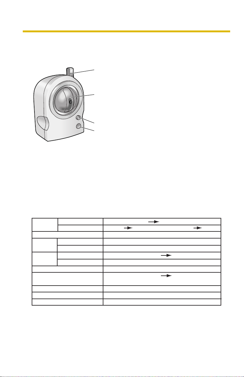
1.2 Camera Feature Locations
1.2.1 Front View
Antenna
Pan/Tilt Part
Do not apply pressure to the pan/tilt portion of the
camera. Any forced movement can damage the internal
mechanism.
Indicator/Privacy Button
Pyroelectric Infrared Sensor (see Getting Started)
Privacy Button
To temporarily deactivate the camera, press the privacy button. Once pressed, the
button changes from green to red. The video will be temporarily turned off, camera
features become unresponsive and the viewed image turns to a gray screen. To
return to normal operation, press the privacy button again. It should turn green
within a few seconds. To restore video, click [Refresh] on the web browser. Privacy
mode can also be controlled from mobile phones or PCs (see page 26 or page 81
of the Operating Instructions on the Setup CD-ROM).
Indicator Display
Powe r
on
Automatic
Setup
Using
DHCP
DEFAULT RESET button
*1The indicator turns orange if the camera is not connected to the LAN.
2
The indicator blinks orange if the camera is not connected to the LAN.
*
*3When the sensor is active, the interval between blinks may increase.
Not on the LAN Orange Orange blinking
On the LAN
Normal Operation*
Finished setting
Getting IP address*
Got IP address
Updating Firmware
Pressing FACTORY
TM
Failure*
UPnP
In Privacy Mode Red
Internal Failure Red blinking
1
Setting
3
Orange Green
2
(The camera restarts about 1 minute later.)
Orange blinking (About a 2-second interval)
Orange and green blinking
Green
Green blinking
Green
Orange blinking
Green
Orange blinking
Orange blinking Turning off
Green blinking
8
Page 9
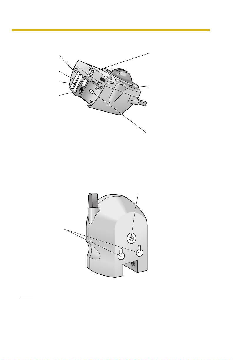
1.2.2 Bottom View
Installation/Troubleshooting
Ethernet
(LAN) port
Serial number
(S/N)
The MAC
address
DC IN jack
1.2.3 Rear View
Used when installing
the camera onto
a wooden wall.
Tripod Mounting
Hole
Used when installing
the camera on a
tripod.
FACTORY DEFAULT
RESET Button
Resets settings to
default (see page 93
of the Operating
Instructions on the
Setup CD-ROM).
Switch
(Wired or Wireless)
Stand Mounting Hole
Used when installing the camera onto a
wooden wall with a stand.
Note
If the ceiling is made of wood, the camera can be installed on the ceiling. See
Panasonic Network Camera support website at http://panasonic.co.jp/pcc/
products/en/netwkcam/ for details.
9
Page 10
Installation/Troubleshooting
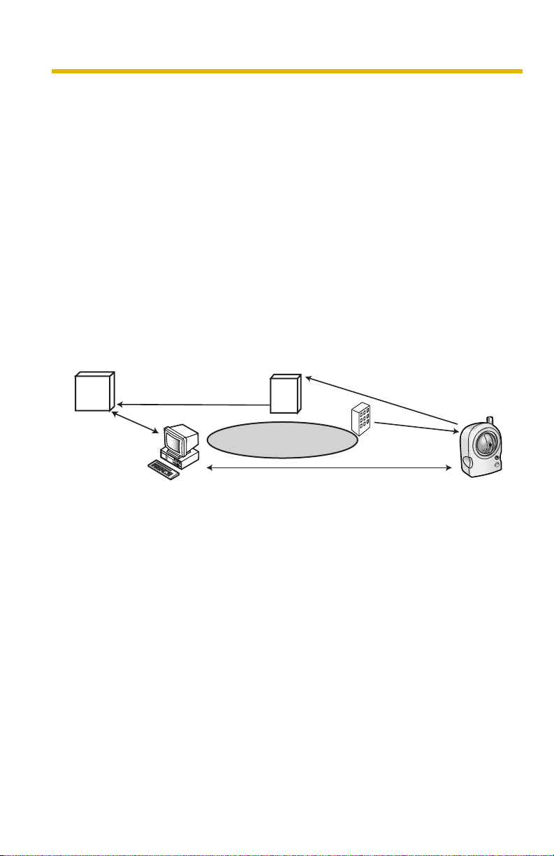
1.3 Viewnetcam.com Service
Viewnetcam.com is a free dynamic DNS (DDNS) service provided by Panasonic.
It allows you to choose an easy-to-remember address (such as
"bob.viewnetcam.com") that you can use to view images from your camera over the
Internet.
What is the advantage of Viewnetcam.com service?
In order to view camera images over the Internet, you need to know your camera’s
global IP address. However, many Internet Service Providers (ISPs) assign their
customers a "dynamic" IP address that changes monthly, weekly, or each time they
log on. Unless you have been assigned a static IP address (an IP address that
does not change periodically) by your ISP, you may find it difficult to access your
camera over the Internet because your IP address changes periodically.
Viewnetcam.com service allows you to access your camera even if your assigned
global IP address changes.
See http://www.viewnetcam.com for details.
How the Viewnetcam.com service works
Viewnetcam.com service server
3.
DNS
server
4.
DNS looks up
current address
New address registered with
DNS server
Internet
5.
Off-site PC
Camera connection established
ISP
1. Your ISP assigns a global IP address to your Internet access account that
changes periodically. This is the address needed to access the camera over
the Internet.
2. When your ISP assigned global IP address changes, your camera
automatically notifies the Viewnetcam.com service server of the new address.
3. The Viewnetcam.com server contacts a Domain Name System (DNS) and
registers your new global IP address to your chosen Viewnetcam.com address
(such as "bob.viewnetcam.com").
4. When you enter your Viewnetcam.com address in your web browser while
away from home or the office, the DNS server looks up the global IP address
assigned to your Viewnetcam.com address.
5. The DNS server finds your current global IP address and allows you to connect
to your camera.
2.
Camera reports new address
On-site Network
Camera
1.
Global IP address
changes
10
Page 11

Installation/Troubleshooting
Notes
• Ask your ISP about what type of IP address you are using.
• Some ISPs assign you a private IP address. In this case, you cannot use
the Viewnetcam.com service. Ask you ISP about what type of IP address
you are using.
• If the camera is using a port number other than 80, the port number must
be specified at the end of the Viewnetcam URL. For example:
Using port 80: http://(Cameraname).viewnetcam.com
Using any other port: http://(Cameraname).viewnetcam.com:Port
Number
11
Page 12

Installation/Troubleshooting
1.4 Connecting the Camera to a Router Supporting UPnP™
To allow access from the Internet with a router supporting UPnPTM, follow the
procedures shown in the Getting Started.
Notes
• In some routers, the UPnPTM feature is disabled by default. Enable your
router's UPnP
camera. See the Panasonic Network Camera support website at http://
panasonic.co.jp/pcc/products/en/netwkcam/ for details.
• If the maximum idle time is set in PPPoE or PPTP connection with your
ISP, disable it on the router. See the router manual for details.
TM
feature following the router manual before you set up the
12
Page 13

Installation/Troubleshooting
1.5 Connecting the Camera to a Router Not Supporting UPnP™
To allow access from the Internet with a router not supporting UPnPTM, follow the
procedures below.
1. Select [Static] on the Network page.
(1) Access the camera (see page 8 of the Operating Instructions on the
Setup CD-ROM).
(2) Click [Setup] tab at the top of the page.
(3) Select [Static] on the Network page.
• The Static IP Address Configuration page is displayed. Make a
note of the IP address and port number, since they are required to
enable port forwarding on the router.
(4) Click [Save] without changing the settings.
(5) Click [Restart].
2. Enable port forwarding on the router.
Using the IP address and port number note written on step 1-(3), enable port
forwarding on the router. See the router manual for how to enable port
forwarding.
3. Register with the Viewnetcam.com service.
Port No.
Modem
*1
TM
. It exchanges a private IP address to a global one.
Port Forwarding feature
vvv.xxx.yyy.zzz:80 192.168.0.253:80
vvv.xxx.yyy.zzz:81 192.168.0.252:81
Router
192.168.0.1
Port Forwarding feature
The port forwarding feature is required to allow access from the Internet with a
router not supporting UPnP
Each camera must be assigned a unique port number.
Global IP address
of the router
vvv.xxx.yyy.zzz:80
vvv.xxx.yyy.zzz:81
Internet
CATV
xDSL
Optical cable
Private IP address
*1
"Port forwarding" may be called "Address translation", "Static IP Masquerade", "Virtual server"
or "Port mapping" in other products.
192.168.0.252
Port No. 81
192.168.0.253
Port No. 80
13
Page 14

Installation/Troubleshooting
1.6 Setting Up the Camera Using the MAC Address on the Setup Program
The Setup Program may not list any cameras due to your firewall or antivirus
software settings on your PC. If you cannot disable your firewall or antivirus
software, you can set up the camera using the camera MAC address as shown
below.
1. Enter the camera MAC address in the data field, and click [Set up camera].
2. After confirming the network settings, click [OK].
14
• After about a minute, the Security: Administrator page is displayed.
Page 15

Installation/Troubleshooting
3. Enter the user name and password, and click [Save].
4. The Enter Network Password window is displayed. Enter the User Name and
Password that were set, and click [OK].
15
Page 16

Installation/Troubleshooting
5. When the Single Camera page is displayed, the setup is completed.
• If Security Warning window is displayed, click [Yes] (see page 17).
• See page 18 for Security Warning window when using Microsoft®
Windows
Notes
• See page 10 of the Operating Instructions on the Setup CD-ROM for the
Single Camera page.
• If you enable the Internet access to the camera, follow the procedures
below.
• When you are using a router supporting UPnP™
®
XP Service Pack 2.
16
1. Enable the Auto Port Forwarding feature on the UPnP page
(see page 40 of the Operating Instructions on the Setup CDROM).
2. Register with the Viewnetcam.com service on the
Viewnetcam.com page (see page 41 of the Operating
Instructions on the Setup CD-ROM).
3. Confirm the Internet access to the camera (see page 8 of
the Operating Instructions on the Setup CD-ROM). If you
cannot access the camera, see page 25.
• When you are using a router not supporting UPnP™
Follow the procedures shown on page 13.
Page 17

Installation/Troubleshooting
Security Warning window
To view a video (Motion JPEG) feature, ActiveX® Controls must be installed. When
trying to display a video for the first time, Security Warning window will be
displayed. When using Windows 2000 or Windows XP, log in as an administrator
to install it.
If you cannot install ActiveX Controls or you cannot see the video in the
Internet Explorer
• Click [Tools] [Internet Options] [Security] tab and click [Custom level] on
the web browser.
(1) Check "Prompt" in "Download signed ActiveX Controls".
(2) Check "Enable" in "Run ActiveX Controls and plug-ins".
• ActiveX Controls can be installed from the file on the Setup CD-ROM.
(1) Restart the PC.
(2) Confirm that Internet Explorer is closed.
(3) Double-click "ocx\ActiveXInst.exe" on the Setup CD-ROM.
Notes
• When the IP address was changed for the camera, enter it on the address bar.
• Video may not be displayed quickly or audio may not be heard immediately.
Wait for a while.
• If you use a proxy server, set the web browser not to access the proxy server
(see page 107 of the Operating Instructions on the Setup CD-ROM).
• In some corporate network environments a firewall may be used for security
purposes. It is possible that this may prevent a video from being displayed. In
this situation we suggest:
• Contact your network administrator.
• Try using regularly refreshed images.
17
Page 18

Installation/Troubleshooting
Security Warning window on Microsoft Windows XP Service Pack 2
To view a video (Motion JPEG) feature, ActiveX Controls must be installed.
Follow the steps shown below to install ActiveX Controls.
1. Click the warning displayed above the tabs, and click [Install ActiveX
Control...].
2. Click [Install].
18
Page 19

Troubleshooting
Installation/Troubleshooting
2 Troubleshooting
The Panasonic Network Camera support website "http://panasonic.co.jp/pcc/
products/en/netwkcam/" includes various technical information other than the
contents in this troubleshooting section. Access it if problems occur.
2.1 About Indicator Display
Problem Cause and Remedy
Indicator lights
or blinks orange.
Indicator
continues
blinking orange.
Indicator
continues
blinking orange
(2-second
interval).
• Ethernet cable is not connected properly.
Connect the Ethernet cable properly.
• PC, Ethernet hub or router is not working.
Confirm that PC, Ethernet hub and router is working.
• The switch on the bottom of the camera is set to WIRELESS
when trying to connect in the wired mode, or the switch is set to
WIRED when trying to connect in the wireless mode.
Set the switch to the corresponding mode.
• The wireless settings are not identical with those of the router.
Set the same SSID, Communication mode and WEP as
those of the router.
• Indicator blinks orange when updating firmware.
If you access the camera on the web browser, Update
Firmware page will be displayed. Update the firmware
following the procedure (see page 85 of the Operating
Instructions on the Setup CD-ROM). If you fail to update the
firmware, see page 35.
• The router on your network is turned off.
Turn the router on, and wait for a while until the ADSL line is
connected.
TM
• An error occurs in UPnP
port forwarding.
Set up the camera again in [Automatic Setup] by the Setup
Program following the Getting Started.
19
Page 20

Troubleshooting
Problem Cause and Remedy
Installation/Troubleshooting
Indicator
continues
blinking green.
Indicator does
not light up.
Indicator
continues
blinking red.
Indicator lights
red.
Indicator
continues
blinking orange
during the
wireless
communication.
• Automatic setup is not complete.
Complete the setup following Getting Started.
• The camera did not get its IP address from the DHCP server.
When setting [Automatic Setup] or [DHCP Setup], the
camera may not get its IP address due to network failures.
Ask your ISP or network administrator for more information.
• Indicator display is disabled.
Check if the indicator control is disabled (see page 80 of the
Operating Instructions on the Setup CD-ROM).
• Confirm that the standard AC adaptor PQLV202 (Order No.
PQLV202X) is being used.
• The camera may be malfunctioning.
If you cannot access the camera, the camera may be
malfunctioning. Call our customer call center.
• The camera is in privacy mode.
To disable the privacy mode, press the privacy button (see
page 8) on the front of the camera or click [Disable]
accessing and logging in to the camera as an administrator.
• Only the MAC addresses for the camera's wireless module are
set.
To enable the MAC address filtering feature on the wireless
router, enter both the MAC addresses for the camera itself
and the camera's wireless module.
20
Page 21

Troubleshooting
2.2 About Camera Setup
Note
If you are experiencing any problems, it is recommended that you
temporarily disable all firewall, pop-up killer, and virus detection
software. Once the problem is identified and corrected, you can restart
the Setup Program.
Problem Cause and Remedy
Installation/Troubleshooting
Automatic Setup
fails using Setup
Program.
Viewnetcam.com
registration fails
using Setup
Program.
• More than 20 minutes have passed, after turning the camera
on.
Disconnect the plug of the AC cord from the outlet, and
reconnect it again. Set up the camera again following the
Getting Started.
• Multiple camera IP addresses are overlapping.
If you install multiple cameras, turn the camera on one by
one.
• Your PC is not connected to the Internet through the router.
Configure the router for the Internet connection from your
PC following the router manual. And register with the
Viewnetcam.com service.
• If you do not receive an E-mail from the Viewnetcam.com
service, your registered E-mail address may be incorrect.
Register your correct E-mail address again at the
Viewnetcam.com website at
"http://www.viewnetcam.com".
• After you registered with the Viewnetcam.com service,
"Expired" is displayed at the Personal (Camera) URL on the
Viewnetcam.com page or at the Camera URL in the DDNS on
the Status page.
Restart the camera, and confirm that your registered URL
is displayed on their pages.
21
Page 22

Troubleshooting
Problem Cause and Remedy
Installation/Troubleshooting
Setup Program
does not list any
cameras.
Setup Program
fails to complete
successfully.
• Your firewall or antivirus software is blocking the connection.
To avoid any possible problems, temporarily disable any
firewall or antivirus software, and set up the camera again.
If you cannot disable your firewall or antivirus software, you
can set up the camera using the MAC address (see page
14).
• The camera is connected over a different network.
Set up the camera from a PC under the same router.
• Confirm that an IP address is assigned to your PC.
If the IP address is not assigned to your PC, assign it to your
PC (see page 103 of the Operating Instructions on the
Setup CD-ROM).
• Network problems may occur during setup.
Confirm that your network is working. Disconnect the plug
of the AC cord from the outlet, and reconnect it again. Then
set up the camera again.
• More than 20 minutes have passed, after turning the camera
on.
Disconnect the plug of the AC cord from the outlet, and
reconnect it again. Set up the camera again following the
Getting Started.
• Administrator page is displayed, and the setup cannot be
completed.
Press the FACTORY DEFAULT RESET button to reset the
camera to default. Set up the camera again. Until the setup
is completed, do not press the privacy button on the front of
the camera.
22
Page 23

Troubleshooting
Problem Cause and Remedy
UPnPTM port
forwarding setup
fails.
•UPnP
TM
is disabled on the router.
TM
Enable UPnP
on the router following the router manual.
• The camera is turned on before the router is turned on.
Turn the router on first, and then turn the camera on.
• The default gateway is not set, or the settings are wrong.
Set the default gateway correctly (see page 31 of the
Operating Instructions on the Setup CD-ROM).
• The router does not support UPnP
Enable port forwarding on your router following the router
manual.
Installation/Troubleshooting
TM
.
The camera IP
address and port
number have
been forgotten.
The password
has been
forgotten.
"The camera fails
to get network
information from
the DHCP
server." is
displayed.
Error is displayed
on the camera
status by the
Setup Program.
• Clicking [Camera Setup] on the Setup Program displays the
camera list. The camera list shows the MAC address labeled
beside the Ethernet (LAN) port. The camera IP address and
port number are shown next to the MAC address.
• Press the FACTORY DEFAULT RESET button to reset the
camera to default. Set up the camera again.
• The hub is not connected to the router.
Connect the hub to the router or connect the camera
directly to the router, disconnect the plug of the AC cord
from the outlet, and then reconnect it again.
• The DHCP server is not functioning on the router.
Enable the DHCP server function following the router
manual.
• The Setup Program causes the error message.
Disconnect the plug of the AC cord from the outlet, and
reconnect it again.
23
Page 24

Troubleshooting
2.3 About Wireless Communication
Problem Cause and Remedy
Installation/Troubleshooting
Wireless
communication
does not work.
Wireless
communication
is unstable.
• Signal strength is weak.
Change the location of the camera or get rid of the obstacle
around the camera.
• SSID and Encryption setting of the camera are different from
those of the wireless router or the wireless LAN card of PC.
SSID and Encryption setting must be identical between the
camera and wireless router.
• The channel for communication is identical with another wireless
network.
The wireless communication may be improved by changing
the channel of the router.
• Another nearby wireless device may be causing interference or
the distance between the wireless camera and your wireless
network may be too great.
Temporarily disable other wireless devices to identify the
source of the interference.
Try repositioning the camera or moving it closer to your
wireless router.
24
Page 25

Troubleshooting
Installation/Troubleshooting
2.4 About Camera Image and Page Display
Problem Cause and Remedy
The Top page is
not displayed.
• The camera IP address has changed.
Enter the new IP address in the address bar of the web
browser.
• Wrong IP address class is assigned to the camera.
IP addresses of the PC and the camera must be in the same
private IP address class. Set the IP address correctly (see
page 103 of the Operating Instructions on the Setup CDROM).
• The router does not allow access to the camera under the router
with the global IP address.
If you access the camera on the LAN, access with the
address for local camera access.
• The network is congested.
Pages may not be displayed immediately. Wait for a while.
• The web browser is accessing the proxy server.
Set the web browser to access the Internet directly (see page
107 of the Operating Instructions on the Setup CD-ROM).
• The camera is malfunctioning.
• The connection type is wrong (see page 31 of the Operating
Instructions on the Setup CD-ROM).
If the camera is not connected to the network in the [Auto
Negotiation] setting, set up the camera and the router seeing
the following table.
Network Camera
Router or hub
Auto Negotiation
100Base-
TX
10Base-T
Full Duplex
Half Duplex
Full Duplex
Half Duplex
Auto
Negotiation
—
—
100Base-TX
Full
Duplex
—
—
—
—
Half
Duplex
—
—
—
10Base-TX
Full
Duplex
Half
Duplex
—
—
—
——
—
—
25
Page 26

Troubleshooting
Problem Cause and Remedy
Installation/Troubleshooting
The Top page is
displayed on the
LAN, but not
displayed from
the Internet.
• The default gateway or DNS server addresses may be wrong.
The correct IP addresses are required especially when you are
using the Viewnetcam.com service.
Assign the correct default gateway and DNS server
addresses (see page 31 of the Operating Instructions on the
Setup CD-ROM).
• The default gateway address may be wrong.
Assign the correct default gateway address (see page 31 of
the Operating Instructions on the Setup CD-ROM).
TM
•UPnP
is disabled on the router.
TM
Enable UPnP
on the router following the router manual.
• Port forwarding is not enabled on the router (see page 13).
Enable port forwarding seeing the router manual for details.
• Firewalls such as packet filtering on the router is blocking
camera access.
Set the router to allow access to the camera seeing the
router manual for details.
• You are accessing the camera with an IP address for local
camera access.
Access the camera with the global IP address of the router
and port number of the camera.
Authentication
windows are
consequently
displayed.
Only half of the
image is
displayed.
• User name and password for the administrator or general users
are changed.
Close the web browser, and access the camera again.
• You are using Internet Explorer 4.xx or lower.
Upgrade Internet Explorer to version 6.0 or greater.
26
Page 27

Troubleshooting
Problem Cause and Remedy
Installation/Troubleshooting
Camera image
is not displayed /
or not displayed
properly.
A gray screen is
displayed.
• ActiveX Controls are not installed in Internet Explorer.
ActiveX Controls should be installed to display video (Motion
JPEG) (see page 11 of the Operating Instructions on the
Setup CD-ROM).
• The network is congested.
Pages may not be displayed immediately. Wait for a while.
• The web browser is accessing the proxy server.
Set the web browser to access the Internet directly (see page
107 of the Operating Instructions on the Setup CD-ROM).
• You may be using the Netscape browser. This browser does not
support many features of this product.
Use Internet Explorer by Microsoft.
• The camera is in privacy mode.
Press the privacy button on the front of the camera (see page
8) or disable the privacy mode logging into the camera as an
administrator. After that, click [Refresh] on the web browser
to display the camera image.
• There are currently more than 20 simultaneous accesses to the
video (Motion JPEG).
Reduce the number of access to below 20, or change the
video to still images.
Video suddenly
changes to still
images.
• Operation time has been specified.
A gray screen is displayed outside the operation time. This is
normal.
• The motion JPEG display period is set.
When you view video continuously, set [Unlimited] for the
limit continuous motion JPEG (see page 55 of the Operating
Instructions on the Setup CD-ROM).
27
Page 28

Troubleshooting
Problem Cause and Remedy
Installation/Troubleshooting
Image is out of
focus.
• The lens has dust, dirt, fingerprints or droplets on it.
Clean the lens with a cotton bud (see page 102 of the
Operating Instructions on the Setup CD-ROM).
• The object is too close to the camera.
The camera cannot focus at short distances
(less than 0.5 m). Locate the object more than 0.5 m away
from the camera.
The color on the
image is
strange.
• White balance does not work well.
Adjust the white balance on the Camera page (see page 45
of the Operating Instructions on the Setup CD-ROM).
• The color display setting on your PC is set lower than 16 bits.
Set the color display 16 bits or higher.
Image flickers. • The object is dark.
Make the area around the camera brighter.
• The AC power source frequency setting is wrong.
Set the proper AC power source frequency used in your area
(see page 45 of the Operating Instructions on the Setup CDROM).
• A bright object may cause horizontal flickers on the image.
An old image is
displayed.
Changing the object improves the flickers. Or adjusting
brightness to the [+] side on the operation bar eases the
flickers.
• The old image is temporarily stored on the web browser.
Set [Every visit to the page] on the web browser to check for
temporary Internet files (see page 110 of the Operating
Instructions on the Setup CD-ROM).
28
Page 29

Troubleshooting
Problem Cause and Remedy
Installation/Troubleshooting
Brightness is
not adjusted for
about half a
minute.
The image
refreshes very
slowly.
• Brightness may not be adjusted for about half a minute, if the
brightness changes sharply.
Locate the camera where the brightness does not change
sharply.
• In very low light it is normal to see random colored noise on the
image.
As the light increases this will improve.
• Multiple users are accessing the camera.
If multiple users are accessing the camera, the image
refreshes slowly.
• You are not using an Ethernet switching hub.
If you view multiple cameras on the Multi-Camera page, the
image refreshes slowly. Use an Ethernet switching hub.
• The image may refresh slowly, depending on image resolution,
image quality, network traffic, PC performance or what object
you view.
• The Max. bandwidth usage is limited.
Increase the max. bandwidth usage on your network (see
page 31 of the Operating Instructions on the Setup CDROM).
• The camera is in color night view mode.
The image stops
refreshing
during the
wireless
communication
with the camera.
The camera
cannot
communicate
with the wireless
terminal.
The image refreshes slowly in color night view mode. Make
the area around the camera brighter.
• The image may stop refreshing because the wireless
communication can be disconnected depending on the
environment.
Click [Refresh] at the tool bar on the web browser.
• Radio waves may not be reaching the wireless terminal or the
camera due to the distance or the existence of obstacles such as
a concrete wall.
Put the wireless terminal near the camera.
29
Page 30

Troubleshooting
Problem Cause and Remedy
Installation/Troubleshooting
The Update
Firmware page
is displayed
when accessing
the camera.
• The camera firmware may be broken because the power was
turned off during the update, etc.
Download the latest firmware from the Panasonic Network
Camera support website and update the firmware.
2.5 About Privacy Mode
Problem Cause and Remedy
Privacy button
does not work.
• The privacy button is not enabled on the Privacy Mode page.
Enable the privacy button on the Privacy Mode page (see
page 81 of the Operating Instructions on the Setup CDROM).
30
Page 31

Troubleshooting
Installation/Troubleshooting
2.6 About Pyroelectric Infrared Sensor
Problem Cause and Remedy
Pyroelectric
infrared sensor
does not work.
• You have not enabled the pyroelectric infrared sensor.
Enable the pyroelectric infrared sensor image buffer/transfer
(see page 68 of the Operating Instructions on the Setup CDROM).
• Pyroelectric infrared sensor stops during privacy mode.
Pyroelectric infrared sensor stops during privacy mode.
Disable the privacy mode (see page 81 of the Operating
Instructions on the Setup CD-ROM).
• The pyroelectric infrared sensor is obstructed.
Even if the obstacle is made of glass or acrylic plastic, it
affects the pyroelectric infrared sensor performance.
Remove the obstacle in front of the sensor.
• The pyroelectric infrared sensor does not detect a temperature
difference outside its range.
The pyroelectric infrared sensor detects a temperature
difference between an object and its surroundings in about 5
m detection range (about 30 ° horizontally and about 85 °
vertically). Therefore, the smaller the temperature difference
is, the shorter the detection range gets. If there is no
temperature difference, the pyroelectric infrared sensor may
not detect anything. On the other hand, if there is a large
temperature difference, the detection range gets longer.
• The pyroelectric infrared sensor is dirty.
Clean the pyroelectric infrared sensor with a soft cloth.
31
Page 32

Troubleshooting
Problem Cause and Remedy
Installation/Troubleshooting
Pyroelectric
infrared sensor
is
malfunctioning.
Lens does not
turn to the
sensor position
after the
pyroelectric
infrared sensor
detects a
temperature
difference.
• The pyroelectric infrared sensor may malfunction in the following
areas.
• Where direct sunlight hits the object
• In a greasy or humid place like a kitchen
• Where there are sharp temperature changes like near an air
conditioner
• Where there is an obstacle such as glass in front of the
camera
• Where the object is exposed to strong light
• Near a radio wave emitting device
Change the camera location (see Getting Started).
• You have not enabled the Lens Position When Triggered setting.
Set [Move to sensor position] at the Lens Position When
Triggered setting (see page 69 of the Operating Instructions
on the Setup CD-ROM).
32
Page 33

Troubleshooting
2.7 About Operation Bar
Problem Cause and Remedy
Installation/Troubleshooting
Pan/Tilt, click to
center and
preset features
do not work.
Part of the
buttons on the
operation bar
are not
displayed.
• Your PC is not connected to the camera.
Click [Refresh] on the web browser. Confirm that the image
refreshes, and you can operate the pan/tilt functions.
• The camera is not turned on.
Confirm that the camera is turned on.
• Multiple users are operating the camera simultaneously.
Wait for a while, and access the camera again.
• The pan/tilt reaches its end.
Confirm that the end display is displayed on the operation
bar.
• The pan/tilt range is restricted.
Adjust the pan/tilt range settings (see page 48 of the
Operating Instructions on the Setup CD-ROM).
• The access level is set to level 1 or 2 on the General User page.
Set the access level to level 3 (see page 53 of the Operating
Instructions on the Setup CD-ROM). Or log in to the camera
as an administrator.
33
Page 34

Troubleshooting
2.8 About Image Buffer/Transfer
Problem Cause and Remedy
Installation/Troubleshooting
The camera
does not
transfer the
image by E-mail
or FTP.
The camera
does not
transfer the
image to a
mobile phone.
The image is
slowed down on
the Buffered
Image page. Or
the camera
transfers the old
image.
• Errors have occurred on the way to the E-mail or FTP server.
See the Protocol column on the Status page (see page 83 of
the Operating Instructions on the Setup CD-ROM), and
check if the error is displayed.
• The default gateway and DNS server addresses are not
assigned correctly.
Assign them correctly (see page 31 of the Operating
Instructions on the Setup CD-ROM).
• Login ID and password for E-mail or FTP are invalid.
Make sure that you enter your correct login ID and password.
• The image quality is not set to [Mobile Phone] on the Image
Buffer/Transfer page.
Set the resolution to [160 x 120] and the image quality to
[Mobile Phone]. Some mobile phones do not support 320 x
240 resolution.
• The transfer interval is too short.
Set the transfer interval longer than the current setting (see
page 62 or page 71 of the Operating Instructions on the
Setup CD-ROM).
34
Page 35

Troubleshooting
2.9 About Other Features
Problem Cause and Remedy
Installation/Troubleshooting
ActiveX cannot
be installed.
The firmware is
not updated.
• Security software disables the ActiveX installation.
Close the security software, and install the ActiveX again.
• The firmware updating is not completed due to power off,
network failure or other causes.
Update the firmware again following the next procedures.
Disconnect the plug of the AC cord of the camera
from the outlet, and reconnect it again.
Enter the IP address on the web browser to access
the camera.
Is the Top page displayed?
Yes
Access the Setup page and click [Status].
Check the firmware version on the Status page.
Is the version updated?
Yes
Update the firmware*1.
The firmware update is completed.
No
No
Shortcut icon is
not displayed in
the My Network
Places folder.
You cannot
solve problems.
1
See page 85 of the Operating Instructions on the Setup CD-
*
ROM about updating firmware.
• UPnP™ Windows component is not installed in Windows XP or
Windows Me.
Install UPnP™ Windows component in Windows XP or
Windows Me (see page 110 of the Operating Instructions on
the Setup CD-ROM).
• Ask the authorized Network Camera dealer.
35
Page 36

The information in this document is subject to change without notice.
Panasonic Communications Co., Ltd.
1-62, 4-chome, Minoshima, Hakata-ku, Fukuoka 812-8531, Japan
Copyright:
This material is copyrighted by Panasonic Communications Co., Ltd., and may be reproduced
for internal use only. All other reproduction, in whole or in part, is prohibited without the written
consent of Panasonic Communications Co., Ltd.
2005 Panasonic Communications Co., Ltd. All Rights Reserved.
Printed in Japan
PSQX3600ZA
KK0205YT0(CE)
 Loading...