

Panasonic BL-C230A, BL-C230CE, BL-C230E Installation Manual
Installation Guide
Network Camera
Model No.
BL-C230
(Wireless/Wired Type)
Model number suffixes (“A”, “CE”, and “E”) are omitted from the following model numbers shown in this document, unless necessary.
BL-C230A, BL-C230CE, BL-C230E
Please read the included Important Information before proceeding.
Complete Operating Instructions and all other documentation can be found on the included CD-ROM.
• This document (Installation Guide) explains how to physically connect the camera to the power supply and network, as well how to mount or place the
camera for regular use.
•The Setup Guide describes how to set up the camera so that it can be accessed using a PC.
• Refer to the Operating Instructions on the CD-ROM for details regarding the camera’s features.
• Refer to the Troubleshooting Guide on the CD-ROM if you have any problems configuring or using the camera.
Abbreviations
• UPnP is the abbreviation for “Universal Plug and Play”.
• The Network Camera is referred to as “the camera” in this document.
• The Setup CD-ROM is referred to as “the CD-ROM” in this document.
© Panasonic System Networks Co., Ltd. 2009
PNQX2272ZA KK1009CQ0
Please read this document before using the product, and save this document for future
reference. Panasonic Network Camera Website:
http://panasonic.net/pcc/ipcam/
Indoor Use Only
Installation Procedure Overview
The following is an overview of the steps required to install and setup the camera. All steps are explained in this document unless otherwise noted.
Preparation
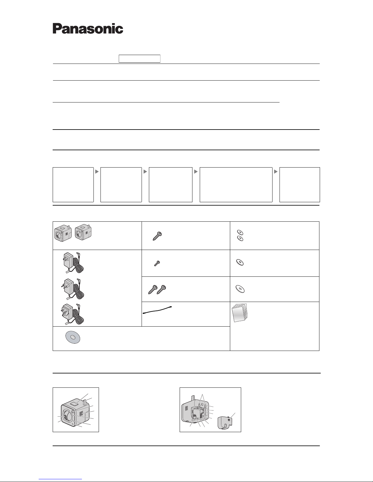
1. Confirm the following items are included in the camera’s packaging.
2. You will need the following additional items to install and configure the camera.
– a PC (see the system requirements in the Important Information document)
– a LAN cable (CAT-5 straight cable)
– a router
Preparation
Confirm that you have all the
items required for
installation.
Camera Diagram
Make sure you know the
names of the camera’s
physical features.
Connections
Connecting the camera to
your network and to the power
outlet.
Setup
• Refer to the included Setup Guide for information
on configuring the camera to be connected
wirelessly to the network, and to be accessed
from a PC.
• BL-C230A only: Refer to the included Setup
Guide for VIERA Connection for information on
registering the camera to a Panasonic VIERA TV.
Mounting
Mounting or placing the
camera.
Main Unit (1 pc.)
The appearance of your
camera depends on which
model you have
purchased.
Screw A (1 pc.)
Order No. XTB4+20AFJ
Used when securing the safety
wire to the wall.
Washer S (2 pcs.)
Order No. XWG35FJ
Used when mounting the camera to the
wall.
AC Adaptor (1 pc.)
Order No. PQLV206Y
Cord Length: About 3 m
(9 feet 10 inches)
BL-C230A
Screw B (1 pc.)
Order No. XTB26+10GFJ
Used for securing the safety
wire to the camera.
Washer M (1 pc.)
Order No. XWG26D12VW
Used when securing the safety wire to
the camera.
Order No. PQLV206CEY
Cord Length: About 3 m
(9 feet 10 inches)
BL-C230CE
Screw C (2 pcs.)
Order No. PQHE5004X
Used for wall mounting the
camera.
Washer L (1 pc.)
Order No. XWG4F16VW
Used when securing the safety wire to
the wall.
Order No. PQLV206EY
Cord Length: About 3 m
(9 feet 10 inches)
BL-C230E
Safety Wire (1 pc.)
Order No. PQME10080Z
Used to secure the camera
when wall mounting it.
Important Information (1 pc.)
Installation Guide
(this document) (1 pc.)
Setup Guide (1 pc.)
Setup Guide (for VIERA Connection)
(1pc.) [BL-C230A Only]
Setup CD-ROM (1 pc.)
Order No. PNQC1016S
Contains the Setup Program needed to configure the camera, as well as the
camera’s documentation.*
*See the included Important Information for a description of each documen t.
BL-C230CE
BL-C230E
BL-C230A
Camera Diagrams
*1 See “PRIVACY Button” on page 4 for information about the PRIVACY button.
*2 See 1.1 Understanding the Camera Indicators in the Troubleshooting Guide on the CD-ROM for indicator m eaning.
*3 BL-C230A only
Front View Rear View
A
B
C
D
E
F
G
H
I
PRIVACY button
*1
Antenna
Built-in sensor (pyroelectric infrared sensor)
Speaker (for built-in alarm)
POWER indicator
*2
AV L IN K in di c at or
*3
Microphone
Lens cover
Lens
J
K
L
M
N
O
P
Q
R
S
Wall mounting holes
Tripod mounting hole
Serial number and MAC address label
LAN port
DC IN jack
External I/O interface
FACTORY DEFAULT RESET button
Safety wire hole
WIRELESS/WIRED switch
Cable cover
D
C
E
A
B
F
G
H
I
J
K
L
M
N
O
P
Q
R
S
2
Connections
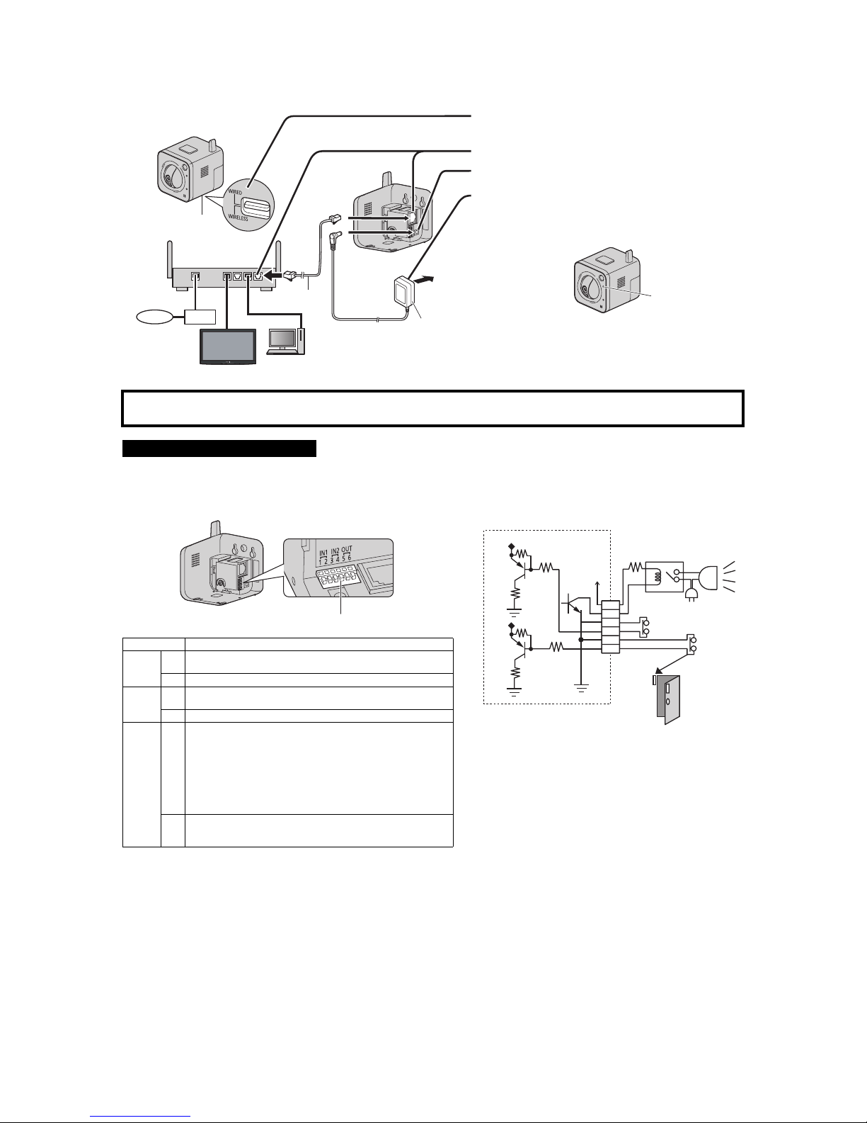
Connect the camera to your router and to the power outlet as described below.
• Before proceeding, confirm that your PC is connected to your router and can access the Internet. Also confirm that your router’s UPn P
™
feature is
enabled. (Most routers have UPnP
™
turned off by default.) Refer to the operating instructions included with your router or to the Panasonic Network
Camera website (http://panasonic.net/pcc/ipcam/) for more information.
The camera’s external I/O interface allows you to connect a device, such as a sensor or motion detector, that can be used to trigger the camera’s image
buffering and transferring features (see Section 2 Using Triggers to Buffer and Transfer Images in the Operating Instructions on the CD-ROM), as well as
the detection notification sound feature (see Section 1.2.11 Additional Features Available While Viewing Live Camera Images in the Operating Instructions
on the CD-ROM).
1 Confirm that the WIRELESS/WIRED switch on the bottom of
the camera is set to WIRED.
2 Connect the LAN cable to the camera and the router.
3 Connect the AC adaptor cord to the DC IN jack.
4 Plug the AC adaptor into the power outlet.
• Confirm that the indicator turns green after about 1
minute. If it does not turn green, see 1.2 POWER
Indicator Issues in the Troubleshooting Guide on the CDROM.
• When you operate the camera, the power ou tlet should be
near the camera and easily accessible.
• Use only specified Panasonic AC adaptor (Order No.
PQLV206Y for BL-C230A, PQLV206CEY for
BL-C230CE, and PQLV206EY for BL-C230E).
• The camera may become warm. This is normal.
After the camera’s indicator turns green, you may set up the camera. Continue by following the procedure described
in the included Setup Guide.
• If the indicator does not turn green, see 1.2 POWER Indicator Issues in the Troubleshooting Guide on the included CD-ROM.
Connecting External I/O interface
Caution
• The external I/O interface is not capable of connecting directly to
devices that require large amounts of current. In some cases, a
custom interface circuit (customer-provided) may have to be used.
Serious damage to the camera may result if a device that exceeds
its electrical capability is connected to the external I/O interface.
• Low voltage/current circuits and high voltage/current circuits are
used in the camera circuit. All wiring should be performed by a
qualified electrician. Incorrect wiring could damage the camera and
cause a fatal electric shock.
Terminal Description
IN1
1
External sensor input. The camera can be triggered by either an open
circuit or a GND short-circuit.
2 GND terminal.
IN2
3
External sensor input. The camera can be triggered by either an open
circuit or a GND short-circuit.
4 GND terminal.
OUT
5
External device control output. Allows you to control an external device
using the output buttons in the camera’s operation bar (for example,
turning a light on or off).
• This terminal’s behavior can be changed (see 7.4 Controlling the
External Output Terminal (BL-C230 Only) in the Operating Instructions
on the CD-ROM).
• This terminal is an open collector circuit. The maximum drawing
current is the same as terminal 6. Do not exceed the voltage of
terminal 6.
6
DC power output terminal.
• DC 8 V–10 V
• Maximum load is 100 mA.
Note
• If excessive force is used when disconnecting wires with pointed objects from
the external I/O interface, terminals may become damaged or the interface may
be pushed inside the camera body and become unusable.
• External devices connected to the camer a’s output terminals cannot
be controlled in the event of a network error or failure. Keep this in
mind when connecting door locks, heat-emitting devices, or other
devices that may be dangerous if they cannot be controlled.
WAN
4321
LAN
WIRELESS/
WIRED switch
Router
Internet
Modem
PC
LAN cable
(Cat-5 straight cable)
AC adaptor
To the
power
outlet
VIERA
(BL-C230A only)
Green
External I/O interface
Light
Door Sensor 1 (Alarm 1)
Door Sensor 2 (Alarm 2)
Relay
Camera
*DC 8 V–10 V
Circuit Diagram Example
9 V*
6
2
1
4
3
5
 Loading...