

Page 1
Getting Started
Network Camera
Model No. BL-C20A
Indoor Use Only
Wireless/Wired Type
Please read the Important Information manual before using.
This Getting Started explains how to connect, set up and mount the
camera. See the Operating Instructions on the Setup CD-ROM for
details about the camera's features.
If you cannot complete the setup, see the Troubleshooting manual
•
on the Setup CD-ROM
This product is a wireless Network Camera. Using a PC and wireless router, it allows you to view images in a residence or from distant places over the
Internet.
Trademarks
•
Adobe, Acrobat and Reader are either registered trademarks or trademarks of Adobe Systems Incorporated in the United States and/or other countries.
• Microsoft, Windows and ActiveX are either registered trademarks or trademarks of Microsoft Corporation in the United States and/or other countries.
• Screen shots reprinted with permission from Microsoft Corporation.
• All other trademarks identified herein are the property of their respective owners.
• This software is based in part on the work of the Independent JPEG Group.
Abbreviations
•
UPnP is the abbreviation for "Universal Plug and Play".
• "Network Camera" is called "Camera" in this manual.
• "Setup CD-ROM" is called "CD-ROM" in this manual.
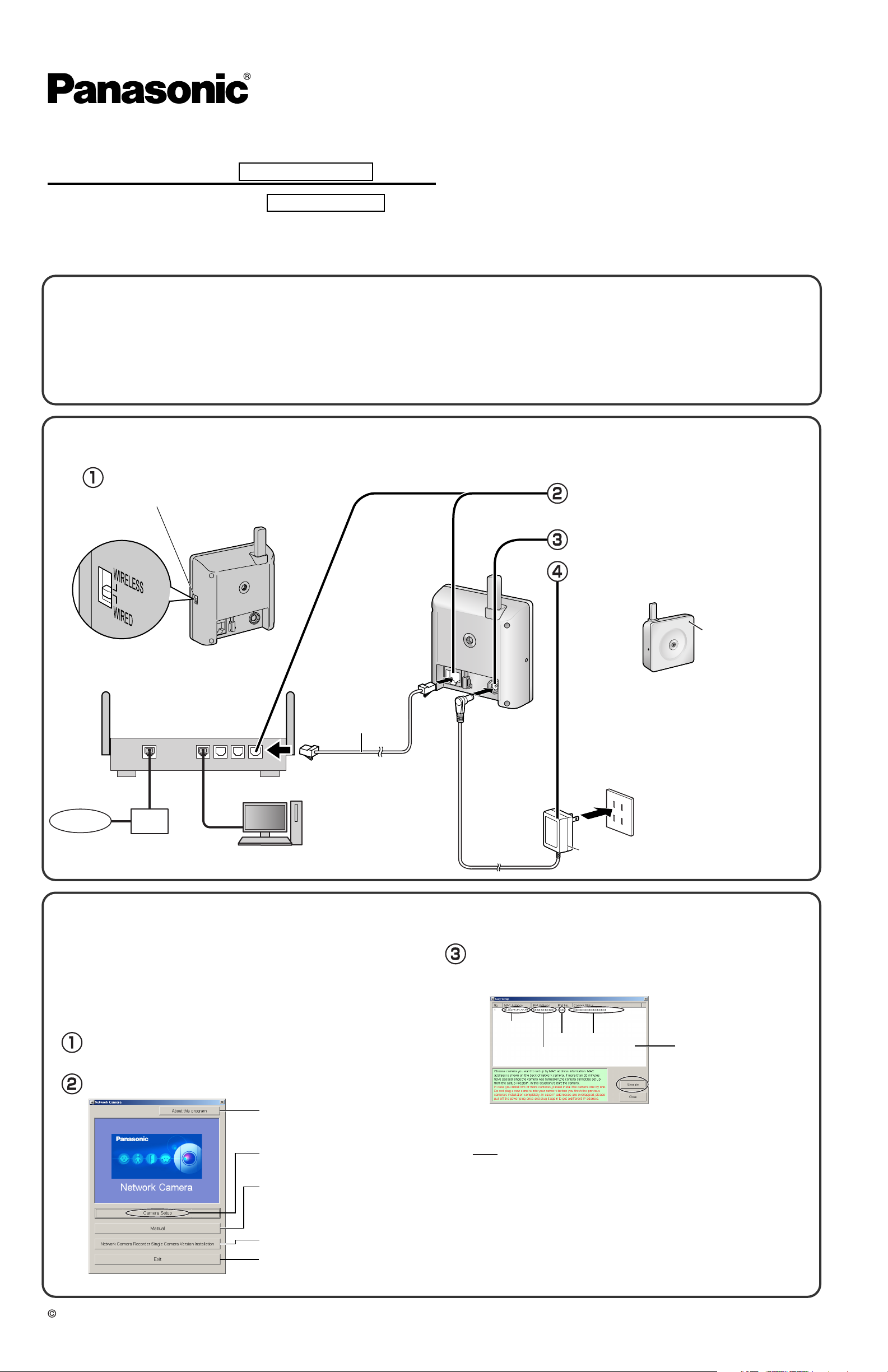
Connect the camera to your router.
1.
•
The PC should be connected to the router, and to the Internet, in advance.
Confirm that the switch on the side of
the camera is set to WIRED.
Switch
Connect the Ethernet cable (customerprovided) to the camera and the router.
.
Internet
<Side>
Router
(Customer-provided)
WAN 4321
Modem
(For setup and display [Customer-provided])
LAN
PC
Ethernet cable
(Straight Cat5 cable,
Customer-provided)
Connect the AC adaptor cord to the DC In
jack.
Plug the AC adaptor into the outlet.
•
Confirm that the indicator lights green after about
1 minute.
The indicator
lights green.
•
When you operate the camera, the power outlet
should be near the camera and easily
accessible.
•
Use only specified Panasonic AC adaptor (Order
No. PQLV206Y).
•
If the indicator does not light green, see page 3
and 4 of Troubleshooting on the CD-ROM.
•
The camera may become warm. This is not a
malfunction.
AC adaptor
Set up the camera.
2.
Important
•
To avoid any possible problems, temporarily disable any firewall
or antivirus software.
•
This procedure explains installation of the camera on the same
network as your PC.
•
Before proceeding, close your web browser.
Insert the CD-ROM into the CD-ROM drive of the PC.
(If the Network Camera Setup window is not displayed automatically,
double-click the "Setup.exe" file on the CD-ROM.)
Click [Camera Setup].
Displays version information
about this program.
Sets up the camera.
Displays the camera manuals.
If your PC does not have Adobe®
Acrobat® Reader®, install it from
the Adobe Reader website.
Installs Network Camera Recorder
Single Camera Version.
Closes the Setup Program.
•
If a Windows Security Alert is displayed, click [Unblock].
Select the camera to set up and click [Execute].
This program searches for the cameras that are connected to the router
•
and displays their MAC Addresses, IP addresses and Port Numbers.
MAC
Address
IP
Address
• The MAC Address on the rear side (see page 6 of the Operating Instructions
on the CD-ROM) of the camera shows which camera you select on the
Camera List window.
Por t
No.
Camera
Status
Camera
List window
Note
• If the indicator does not light green, check the connection (see page 4 of the
Operating Instructions on the CD-ROM, or page 3 and 4 of the
Troubleshooting).
• If more than 20 minutes have passed since the camera was turned on, the
camera cannot be set up from the Setup Program. In this situation, disconnect
the AC adaptor from the outlet, and reconnect it again.
• The Setup Program may not list any cameras due to your firewall or antivirus
software settings on your PC. If you cannot disable your firewall or antivirus
software, you can set up the camera by entering the camera MAC address. The
camera's MAC address can be found on the label affixed to the rear of each
camera. See page 6 of the Operating Instructions on the CD-ROM for details.
2005 Panasonic Communications Co., Ltd. All Rights Reserved.
PQQX14942ZA KK1105JT0
Page 2
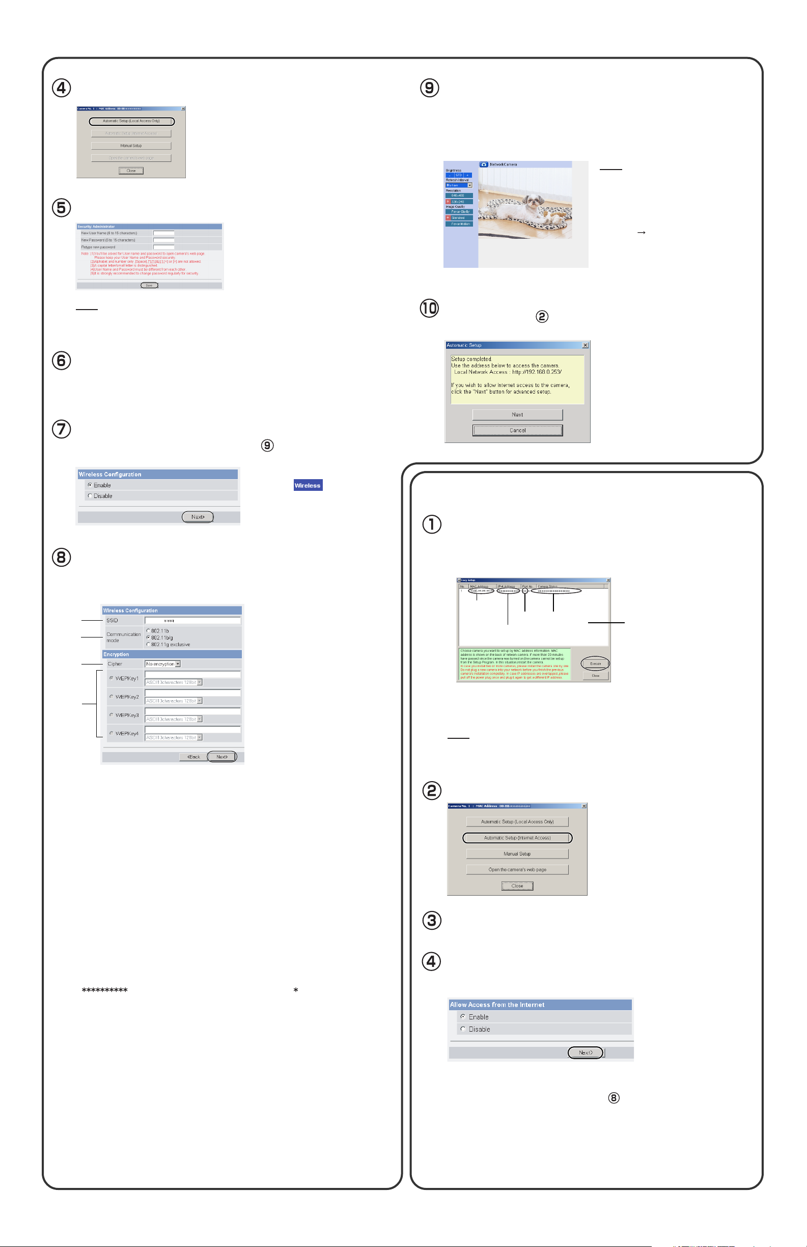
Click [Automatic Setup (Local Access Only)].
Enter the user name and password, and click [Save].
When the Single Camera page is displayed, setup
is complete.
•
If the Security Warning window is displayed when installing ActiveX
Controls, click [Yes].
•
To install ActiveX Controls on Microsoft® Windows® XP Service Pack
2, see "Security Warning window on Microsoft Windows XP Service
Pack 2" on the next page.
Note
To ensure that the most current image
is displayed, Internet Explorer should
be configured as follows. This will not
have a negative effect on normal use.
1. While viewing any website, click
[Tools] [Internet Options].
2. In the section "Temporary Internet
Files", click [Settings] and check
[Every visit to the page].
®
Note
Make a note of the user name and password.
The Enter Network Password window is displayed.
Enter the user name and password that were set, and
click [OK].
To set Wireless Configuration, check [Enable] and click [Next>].
•
When [Disable] is selected, skip to step .
•
Wireless Configuration can also
be set at on the Setup
Page. (See page 36 of the
Operating Instructions on the
CD-ROM.)
Set the Wireless Configuration according to the wireless
settings of the router and click [Next>].
•
For more information about wireless setting, see
http://panasonic.co.jp/pcc/products/en/netwkcam/
1
2
NetCam
Click [Next] to set up the Internet access to the camera and go to step in "To Set Up Internet Access
to the Camera".
•
Click [Cancel] and go to the last
page if you will mount the camera.
•
If you set wireless configuration,
confirm the wireless LAN setup
seeing the next page.
Set up Internet access to the camera.
3.
Select the camera on the camera list to set up the
Internet access and click [Execute].
•
This program searches for the cameras that are connected to the router
and displays their MAC Addresses, IP addresses and Port Numbers.
MAC
Address
IP
Address
Por t
No.
Camera
Status
Camera
List window
3
4
1. Set the SSID.
Set the name of the wireless network.
2. Select the Communication mode.
These are IEEE Communication modes. Select the same
that of the router to which the camera is connected.
802.11b (IEEE802.11b) :
802.11b/g (IEEE802.11g) : Either the 802.11b or 802.11g router can be
802.11g exclusive (IEEE802.11g) : Only the 802.11g router can be connected.
3. Select encrypting or not encrypting.
Selecting WEP can encrypt data within the wireless LAN.
WEP: Encrypting (setting WEP) makes it difficult for unauthorized users to read
data within the wireless LAN, even if they can receive it. To encrypt data, set
the same encryption key to every terminal within the wireless LAN. There are
3 kinds of encryption key: 64 bit, 128 bit and 152 bit. Security level of
encryption increases in order of length as follows: 64 bit, 128 bit and 152 bit.
No encryption: select when not using encryption.
4. Set the WEPKey1–4.
Selecting [WEP] at Cipher enables you to set WEPKey1–4. One or all of the four
keys can be set. Check the key number set to the router, and set the same key as at
the router.
: The entered WEPKey will be displayed as " "s regardless of the key
type selected.
<Example>
HEX, 10 characters 64 bit : 012345abcd
HEX, 26 characters 128 bit : 0123456789abcdef012345abcd
HEX, 32 characters 152 bit : 0123456789abcdef0123456789abcdef
ASCII 5 characters 64 bit : 012yz
ASCII 13 characters 128 bit : 0123456uvwxyz
ASCII 16 characters 152 bit : 0123456789uvwxyz
Only the 802.11b wireless router can be connected.
connected.
Communication mode as
•
The MAC Address on the rear side (see page 6 of the Operating
Instructions on the CD-ROM.) of the camera shows which camera you
select on the camera list window.
Note
If more than 20 minutes have passed since the camera was turned on, the
camera cannot be set up from the Setup Program. In this situation, restart the
camera.
Click [Automatic Setup (Internet Access)].
The Enter Network Password window is displayed. Enter the
user name and password that were set, and click [OK].
When using a router that supports UPnPTM, check [Enable].
When using a router that does not support UPnP
TM
, check
[Disable]. Then click [Next>].
•
Check if your router supports UPnPTM referring to the router's
manual.
•
If you select [Disable], skip to step on the next page.
Page 3

Registration with the "Viewnetcam.com
FREE DynamicDNS service"
By registering with the Viewnetcam.com FREE DynamicDNS service, you
can create a personalized web address at which your camera's live video
can always be found on the Internet. For detailed information, access
"http://www.viewnetcam.com".
To register with the "Viewnetcam.com FREE DynamicDNS
service", check [Register with Viewnetcam.com] and click
[Next>].
•
If you selected [Do not register with Viewnetcam.com], skip to step .
When "Setup completed" is displayed, click [To Single
Camera page].
•
When [Enable] was selected
at step .
•
When [Disable] was selected at
step .
Note
•
The port number must be specified at the end of the camera URL.
For example
Using port 80: http://(Cameraname).viewnetcam.com
or http://IP Address
Using any other port: http://(Cameraname).viewnetcam.com:Port Number
or http://IP Address:Port Number
•
The URL for the local network access may be different from the one set up on
the previous page.
The Enter Network Password window is displayed.
Enter the user name and password that were set, and click
[OK].
The "Viewnetcam.com FREE DynamicDNS service" website is
displayed. Follow the displayed instructions for registration.
•
If the message "Failed to configure the router's Port Forwarding by UPnP" is
displayed, your router may not support UPnP
Enable your router's UPnP
router's manual, and try Automatic Setup again. For more information about
setting up a router, refer to the Panasonic Network Camera support web-site
at
http://panasonic.co.jp/pcc/products/en/netwkcam/
•
If the message "Failed to register with Viewnetcam.com." is displayed,
confirm that the router is connected to the Internet.
TM
or set Port Forwarding manually following the
TM
or UPnPTM is not enabled.
Confirming the Wireless LAN Setup
After setting each item for the wireless LAN, confirm that the camera works
correctly.
Unplug the Ethernet cable and turn off the power (disconnect
the AC adaptor).
Set the switch on the side of the camera to WIRELESS.
Turn on the power by connecting the AC adaptor to the
outlet.
When the Single Camera page is displayed, setup is complete.
•
If a Security Warning window is displayed when installing ActiveX
Controls, click [Yes].
•
To install ActiveX Controls on Microsoft Windows XP Service Pack
2, see "Security Warning window on Microsoft Windows XP Service
Pack 2" below.
Note
To ensure that the most current image is
displayed, Internet Explorer should be
configured as follows. This will not have a
negative effect on normal use.
1. While viewing any website, click [Tools]
[Internet Options].
2. In the section "Temporary Internet
Files", click [Settings] and check [Every
visit to the page].
•
If you set wireless configuration, confirm the wireless LAN setup below.
Enter "http://IP address (or URL):Port No." in the address field
and press [Enter].
(When port number is 80 (default), you do not need to enter port number.)
•
When the following Top Page is displayed, the wireless LAN setup is
successful.
•
If the Top Page was not displayed, the settings
for the camera are not identical with those for the
router. Check the settings by using wired connection.
If the settings are correct and you use a proxy
server, set the web browser not to access the
proxy server.
If the Top Page is not displayed even after trying
these methods, contact the retailer.
•
It takes about 1 minute for the new settings to be
effective.
•
It is not possible to access the camera simultane-
ously by both wired and wireless connection.
•
Some routers need to be restarted after setting
the camera's switch to WIRELESS.
Start up the web browser on the PC.
Security Warning window on Microsoft Windows XP Service Pack 2
To view a video (Motion JPEG), ActiveX Controls must be installed. Follow the steps shown below to install ActiveX Controls.
Click the warning displayed above the tabs, and click [Install
ActiveX Control...].
Click [Install].
Page 4

4.
Mount the camera.
The camera can be mounted in the following ways.
Note
•
Do not mount the camera where the sun light directly hits the camera or in
outdoor-type housing without a temperature control system. The camera may
malfunction due to high temperature.
•
When you mount the camera, always hook the AC adaptor cord to the hook.
Hook for
AC adaptor cord
Stand Mount Tripod Mount
Note
Disconnect all cables from the camera. Reconnect the cables after mounting
the camera.
Stand/Tripod
Mountigng Hole
Mounting Screw
Position Lock
Loosen the Position Lock located
on the rear side of the flexible
stand.
Turn the mounting screw to
attach the camera.
Adjust the angle, then
fasten the Position Lock.
•
This product is for indoor use only. Do not use it outdoors.
•
The camera may become warm. This is not a malfunction.
•
Mount the camera where the AC adaptor can reach an outlet, or use an
extension cord (customer-provided).
•
Do not mount the camera upside down, as the image will be displayed upside
down.
To p
Make sure the indicator is
always in the upper right
Bottom
Stand/Tripod
Mounting Hole
Note
•
Do not use a tripod screw with
a thread of 6 mm (1/4 inches)
or more. (This may damage the
Stand/Tripod mounting hole.)
•
The camera cannot be
mounted depending on the
shape of the camera platform.
corner.
Tripod
(customer
-provided)
Flexible
Stand
Ceiling Mount
Note
• Do not mount the camera upside down, as the image will be displayed upside
down.
• We recommend only mounting the camera using the provided hardware.
Mounting in any other manner may cause the camera to fall, resulting in
personal injury or damage to the camera.
• To reduce the load on the mounting hardware, dress the cables neatly and
secure with tape.
• Disconnect all cables from the camera. Reconnect the cables after mounting
the camera.
Mount the flexible stand firmly to the
ceiling with the two screws (included).
Loosen the Position Lock located on
the rear side of the flexible stand,
and turn the Mounting Screw to
attach the camera.
Position Lock
Screw
Wall Mount
Note
• Do not mount the camera upside down, as the image will be displayed upside
down.
• We recommend only mounting the camera using the provided hardware.
Mounting in any other manner may cause the camera to fall, resulting in
personal injury or damage to the camera.
• To reduce the load on the mounting hardware, dress the cables neatly and
secure with tape.
• Disconnect all cables from the camera. Reconnect the cables after mounting
the camera.
Mount the flexible stand firmly to the
wall with the two screws (included).
Allow sufficient space between the
ceiling and the flexible stand to turn
the Position Lock.
Loosen the Position Lock located on
the rear side of the flexible stand,
and turn the Mounting Screw to
attach the camera.
Stand/Tripod
Mounting
Hole
Allow sufficient space
between the wall and
the flexible stand to
turn the Position Lock.
• Do not mount the camera on a soft
material. The camera may fall and
be damaged.
• Use appropriate screws for the
material of the ceiling.
Adjust the angle, then fasten the
Position Lock.
Position Lock
Stand/Tripod
Screw
Mounting Hole
Connect the AC adaptor cord (and
Ethernet cable, if necessary) to the
camera and dress the cables neatly
and secure with tape (customerprovided).
Tape
(customer-provided)
Mounting
Screw
• Do not mount the camera on a soft
material. The camera may fall and
be damaged.
• Use appropriate screws for the
material of the wall.
Adjust the angle, then fasten the
Position Lock.
Position Lock
Position
Lock
Mounting Screw
Indicator
Connect the AC adaptor cord (and
Ethernet cable, if necessary) to the
camera and dress the cables neatly
and secure with tape (customerprovided).
Tape
(customer-provided)
 Loading...