

Page 1

Operating Instructions
Network Camera
Model No. BL-C20
Indoor Use Only
Please read this manual before using, and save this manual for future reference.
Page 2

Operating Instructions
Main Features
Wireless Communication
This Network Camera is compatible with a wireless system based on IEEE
802.11b/g. Wireless installation is playing an ever increasing role in flexible
communication. The use of encryption ensures security on this kind of network.
Communication via Ethernet cable is also available.
Digital zoom feature
This camera has a 10× digital zoom feature. This feature allows you to increase or
decrease the size of objects on the Single Camera screen, the Multi Camera
screen, and the Buffered Image screen. This makes it easy to view distant objects.
A mouse wheel operation or clicking the right mouse button increase or decrease
the size of the object.
Color Night View Mode
The color night view mode provides better image quality and low light performance
*3
(4 lx
).
Multi-Camera Support
The Multi-Camera page displays the moving images from up to 4 cameras. This
camera allows you to switch between 3 sets of 4 cameras. Additionally, static
images from a maximum of 12 cameras can be displayed on a single page.
DynamicDNS Service Support
DynamicDNS service allows you to access the camera over the Internet with a
domain name of your choice (e.g. bob.viewnetcam.com) instead of a global IP
address.
Multi-Language Display
The Top page, Single Camera and Multi-Camera page can be displayed in English,
French, German, Italian, Spanish, Russian, Simplified Chinese, Korean or
Japanese. The Setup, Maintenance and Support pages are displayed only in
English, Japanese, French or Simplified Chinese.
Motion Detection feature
The camera has a Motion Detection feature that detects movement, such as
people, based on the preset threshold and sensitivity of the camera. You can buffer
the camera images, transfer images to an FTP server or send E-mails using the
Motion Detection function as a trigger.
*1
*2
*1
This feature is not available when viewing on a mobile phone.
*2
As the magnification increases, the image quality decreases.
*3
The brightness about 1 m away under auxiliary fluorescent light. When the object darkens,
color night view mode is automatically enabled. The frame rate and the image quality
decrease in color night view mode. Also, images of moving people or animals may be blurred.
2
Page 3

Operating Instructions
Trademarks
• Adobe, Acrobat and Reader are either registered trademarks or trademarks of
Adobe Systems Incorporated in the United States and/or other countries.
• Microsoft, Windows, Hotmail and ActiveX are either registered trademarks or
trademarks of Microsoft Corporation in the United States and/or other
countries.
• Screen shots reprinted with permission from Microsoft Corporation.
• All other trademarks identified herein are the property of their respective
owners.
• This software is based in part on the work of the Independent JPEG Group.
Abbreviations
• UPnP is the abbreviation for "Universal Plug and Play".
• "Network Camera" is called "camera" in this manual.
• "Setup CD-ROM" is called "CD-ROM" in this manual.
3
Page 4

Operating Instructions
Precaution
Information on Disposal for Users of Waste Electrical &
Electronic Equipment (private households)
This symbol on the products and/or accompanying documents
means that used electrical and electronic products should not be
mixed with general household waste.
For proper treatment, recovery and recycling, please take these
products to designated collection points, where they will be
accepted on a free of charge basis. Alternatively, in some
countries you may be able to return your products to your local
retailer upon the purchase of an equivalent new product.
Disposing of this product correctly will help to save valuable resources and
prevent any potential negative effects on human health and the
environment which could otherwise arise from inappropriate waste
handling. Please contact your local authority for further details of your
nearest designated collection point.
Penalties may be applicable for incorrect disposal of this waste, in
accordance with national legislation.
For business users in the European Union
If you wish to discard electrical and electronic equipment, please contact
your dealer or supplier for further information.
Information on Disposal in other Countries outside the
European Union
This symbol is only valid in the European Union.
If you wish to discard this product, please contact your local authorities or
dealer and ask for the correct method of disposal.
4
Page 5

Operating Instructions
Informations relatives à l’évacuation des déchets,
destinées aux utilisateurs d’appareils électriques et
électroniques (appareils ménagers domestiques)
Lorsque ce symbole figure sur les produits et/ou les documents
qui les accompagnent, cela signifie que les appareils
électriques et électroniques ne doivent pas être jetés avec les
ordures ménagères.
Pour que ces produits subissent un traitement, une
récupération et un recyclage appropriés, envoyez-les dans les
points de collecte désignés, où ils peuvent être déposés
gratuitement. Dans certains pays, il est possible de renvoyer les produits au
revendeur local en cas d’achat d’un produit équivalent.
En éliminant correctement ce produit, vous contribuerez à la conservation
des ressources vitales et à la prévention des éventuels effets négatifs sur
l’environnement et la santé humaine qui pourraient survenir dans le cas
contraire.
Afin de connaître le point de collecte le plus proche, veuillez contacter vos
autorités locales.
Des sanctions peuvent être appliquées en cas d’élimination incorrecte de
ces déchets, conformément à la législation nationale.
Utilisateurs professionnels de l’Union européenne
Pour en savoir plus sur l’élimination des appareils électriques et
électroniques, contactez votre revendeur ou fournisseur.
Informations sur l’évacuation des déchets dans les pays
ne faisant pas partie de l’Union européenne
Ce symbole n’est reconnu que dans l’Union européenne.
Pour vous débarrasser de ce produit, veuillez contacter les autorités locales
ou votre revendeur afin de connaître la procédure d’élimination à suivre.
5
Page 6

Operating Instructions
Benutzerinformationen zur Entsorgung von elektrischen
und elektronischen Geräten (private Haushalte)
Entsprechend den grundlegenden Firmengrundsetzen der
Panasonic-Gruppe wurde ihr Produkt aus hochwertigen
Materialien und Komponenten entwickelt und hergestellt, die
recycelbar und wieder verwendbar sind.
Dieses Symbol auf Produkten und/oder begleitenden
Dokumenten bedeutet, dass elektrische und elektronische
Produkte am Ende
entsorgt werden müssen.
Bringen Sie bitte diese Produkte für die Behandlung,
Rohstoffrückgewinnung und Recycling zu den eingerichteten kommunalen
Sammelstellen bzw. Wertstoffsammelhöfen, die diese Geräte kostenlos
entgegennehmen.
Die ordnungsgemäße Entsorgung dieses Produkts dient dem
Umweltschutz und verhindert mögliche schädliche Auswirkungen auf
Mensch und Umwelt, die sich aus einer unsachgemäßen Handhabung der
Geräte am Ende Ihrer Lebensdauer ergeben könnten.
Genauere Informationen zur nächstgelegenen Sammelstelle bzw.
Recyclinghof erhalten Sie bei Ihrer Gemeindeverwaltung.
ihrer Lebensdauer vom Hausmüll getrennt
Für Geschäftskunden in der Europäischen Union
Bitte treten Sie mit Ihrem Händler oder Lieferanten in Kontakt, wenn Sie
elektrische und elektronische Geräte entsorgen möchten. Er hält weitere
Informationen für sie bereit.
Informationen zur Entsorgung in Ländern außerhalb der
Europäischen Union
Dieses Symbol ist nur in der Europäischen Union gültig.
6
Page 7

Operating Instructions
Informazioni per gli utenti sullo smaltimento di
apparecchiature elettriche ed elettroniche obsolete (per i
nuclei familiari privati)
Questo simbolo sui prodotti e/o sulla documentazione di
accompagnamento significa che i prodotti elettrici ed elettronici
usati non devono essere mescolati con i rifiuti domestici
generici.
Per un corretto trattamento, recupero e riciclaggio, portare
questi prodotti ai punti di raccolta designati, dove verranno
accettati gratuitamente. In alternativa, in alcune nazioni
potrebbe essere possibile restituire i prodotti al rivenditore locale, al
momento dell’acquisto di un nuovo prodotto equivalente.
Uno smaltimento corretto di questo prodotto contribuirà a far risparmiare
preziose risorse ed evitare potenziali effetti negativi sulla salute umana e
sull’ambiente, che potrebbero derivare, altrimenti, da uno smaltimento
inappropriato. Per ulteriori dettagli, contattare la propria autorità locale o il
punto di raccolta designato più vicino.
In caso di smaltimento errato di questo materiale di scarto, potrebbero
venire applicate delle penali, in base alle leggi nazionali.
Per gli utenti aziendali nell’Unione Europea
Qualora si desideri smaltire apparecchiature elettriche ed elettroniche,
contattare il rivenditore o il fornitore per ulteriori informazioni.
Informazioni sullo smaltimento in nazioni al di fuori
dell’Unione Europea
Questo simbolo è valido solo nell’Unione Europea.
Qualora si desideri smaltire questo prodotto, contattare le autorità locali o il
rivenditore e chiedere informazioni sul metodo corretto di smaltimento.
7
Page 8

Operating Instructions
Información sobre la eliminación para los usuarios de
equipos eléctricos y electrónicos usados (particulares)
La aparición de este símbolo en un producto y/o en la
documentación adjunta indica que los productos eléctricos y
electrónicos usados no deben mezclarse con la basura
doméstica general.
Para que estos productos se sometan a un proceso adecuado
de tratamiento, recuperación y reciclaje, llévelos a los puntos de
recogida designados, donde los admitirán sin coste alguno.
En algunos países existe también la posibilidad de devolver los productos a
su minorista local al comprar un producto nuevo equivalente.
Si desecha el producto correctamente, estará contribuyendo a preservar
valiosos recursos y a evitar cualquier posible efecto negativo en la salud de
las personas y en el medio ambiente que pudiera producirse debido al
tratamiento inadecuado de desechos.
Póngase en contacto con su autoridad local para que le informen
detalladamente sobre el punto de recogida designado más cercano.
De acuerdo con la legislación nacional, podrían aplicarse multas por la
eliminación incorrecta de estos desechos.
Para empresas de la Unión Europea
Si desea desechar equipos eléctricos y electrónicos, póngase en contacto
con su distribuidor o proveedor para que le informe detalladamente.
Información sobre la eliminación en otros países no
pertenecientes a la Unión Europea
Este símbolo sólo es válido en la Unión Europea.
Si desea desechar este producto, póngase en contacto con las autoridades
locales o con su distribuidor para que le informen sobre el método correcto
de eliminación.
8
Page 9

Operating Instructions
9
Page 10

Operating Instructions
Informace pro uživatele k likvidaci elektrických a
elektronických zařízení (domácnosti)
Tento symbol na produktech anebo v průvodních dokumentech
znamená, že použité elektrické a elektronické výrobky nesmí být
přidány do běžného komunálního odpadu.
Ke správné likvidaci, obnově a recyklaci doručte tyto výrobky na
určená sběrná místa, kde budou přijata zdarma. Alternativně v
některých zemích můžete vrátit své výrobky místnímu prodejci
při koupi ekvivalentního nového produktu.
Správnou likvidací tohoto produktu pomůžete zachovat cenné přírodní
zdroje a napomáháte prevenci potenciálních negativních dopadů na životní
prostředí a lidské zdraví, což by mohly být důsledky nesprávné likvidace
odpadů. Další podrobnosti si vyžádejte od místního úřadu nebo nejbližšího
sběrného místa.
Při nesprávné likvidaci tohoto druhu odpadu mohou být v souladu s
národními předpisy uděleny pokuty.
Pro podnikové uživatele v zemích Evropské unie
Chcete-li likvidovat elektrická a elektronická zařízení, vyžádejte si potřebné
informace od svého prodejce nebo dodavatele.
Informace k likvidaci v ostatních zemích mimo Evropskou
unii
Tento symbol je platný jen v Evropské unii.
Chcete-li tento výrobek zlikvidovat, vyžádejte si potřebné informace o
správném způsobu likvidace od místních úřadů nebo od svého prodejce.
10
Page 11

Operating Instructions
Oplysninger til brugerne om afhændelse af elektriske
apparater og elektronisk udstyr (private husholdninger)
Når produkter og/eller medfølgende dokumenter indeholder dette
symbol, betyder det, at elektriske apparater og elektronisk
udstyr ikke må smides ud sammen med det almindelige
husholdningsaffald.
For at sikre en korrekt behandling, indsamling og genbrug, skal
du aflevere disse produkter på dertil indrettede
indsamlingssteder, hvor de vil blive modtaget uden ekstra
omkostninger. I nogle lande er der også mulighed for, at du kan
indlevere dine produkter hos den lokale forhandler, hvis du køber
et nyt og tilsvarende produkt.
Hvis du afhænder dette produkt på korrekt vis, vil det være med at spare på
de værdifulde naturlige råstoffer og forhindre eventuelle negative
påvirkninger på folkesundheden og miljøet, hvilket ellers kunne blive
følgerne af en forkert håndtering af affaldet. Kontakt de lokale myndigheder
for at få yderligere oplysninger om, hvor du kan finde det nærmeste
indsamlingssted.
I visse lande vil en forkert afhændelse af affaldet medføre en bødestraf i
henhold til de gældende bestemmelser på området.
Professionelle brugere i EU
Hvis du ønsker at smide elektriske apparater eller elektronisk udstyr ud, skal
du kontakte din forhandler eller leverandør for at få yderligere oplysninger.
Oplysninger om afhændelse i lande uden for EU
Dette symbol er kun gyldigt i EU.
Hvis du ønsker at afhænde dette produkt, skal du rette henvendelse til de
lokale myndigheder eller din forhandler. Her kan du få oplysninger om,
hvordan du bedst kommer af med produktet.
11
Page 12

Operating Instructions
Tietoja sähkö- ja elektroniikkalaitteiden hävittämisestä
(kotitaloudet)
Tämä symboli tuotteissa ja/tai niiden käyttöohjeissa osoittaa,
että käytettyjä sähkö- ja elektroniikkalaitteita ei saa hävittää
tavallisen kotitalousjätteen mukana.
Jotta laitteet käsitellään asianmukaisesti, toimita ne
kierrätyspisteisiin, jotka vastaanottavat tällaisia laitteita
ilmaiseksi. Joissakin maissa kuluttajat voivat myös palauttaa
käytetyt laitteet paikalliselle jälleenmyyjälle, jos he ostavat tilalle
uuden vastaavanlaisen tuotteen.
Tämän tuotteen asianmukainen hävittäminen säästää luonnonvaroja ja
estää mahdollisesti muutoin syntyviä ympäristö- ja terveysongelmia.
Lähistöllä sijaitsevista kierrätyspisteistä saa lisätietoja paikallisilta
viranomaisilta.
Jätelaissa ja rikoslaissa on säädetty rangaistus roskaamisesta ja
lainvastaisesta hävittämisestä.
Yrityskäyttäjät Euroopan unionissa
Jos haluat hävittää sähkö- ja elektroniikkalaitteita, kysy lisätietoja
jälleenmyyjältä tai tavarantoimittajalta.
Tietoja jätteiden käsittelystä Euroopan unionin
ulkopuolella
Tämä symboli on käytössä vain Euroopan unionissa.
Jos haluat hävittää tämän tuotteen, tiedustele oikeaa hävitystapaa
paikallisilta viranomaisilta tai jälleenmyyjältä.
12
Page 13

Operating Instructions
Έ
Πληροφορίες για την απόρριψη ηλεκτρικών και
ηλεκτρονικών συσκευών (οικιακής χρήσης)
Αυτή η σήµανση στα προϊόντα και/ή στα συνοδευτικά τους
έντυπα υποδηλώνει ότι τα εν λόγω ηλεκτρικά και ηλεκτρονικά
προϊόντα δεν πρέπει να απορριφθούν µαζί µε οικιακά απορρίµµ
ατα.
Προκειµένου να πραγµατοποιηθεί η κατάλληλη επεξεργασία και
ανακύκλωση, αποσύρετε αυτά τα προϊόντα σε ανάλογα σηµεία
περισυλλογής, όπου θα γίνουν δεκτά χωρίς χρέωσή σας.
Εναλλακτικά, σε ορισµένες χώρες, µπορείτε να επιστρέψετε τα
προϊόντα σε τοπικά καταστήµατα µε σκοπό την αγορά ανάλογου
νέου προϊόντος.
Η ορθή απόρριψη αυτού του προϊόντος βοηθάει στην εξοικονόµηση πολύτι
µων φυσικών πόρων και στην αποφυγή τυχόν αρνητικών επιπτώσεων για
την ανθρώπινη υγεία και το περιβάλλον, οι οποίες µπορεί να προκληθούν
από λανθασµένη διαχείριση του εν λόγω απορρίµµατος.
Επικοινωνήστε µε τις τοπικές αρχές για περισσότερες πληροφορίες
σχετικά µε το πλησιέστερο ανάλογο σηµείο περισυλλογής.
Ενδέχεται να επιβληθούν κυρώσεις για λανθασµένη απόρριψη του εν λόγω
προϊόντος, σύµφωνα µε τη νοµοθεσία της χώρας σας.
Προϊόντα επαγγελµατικής χρήσης, Ευρωπαϊκή Ένωση
Αν επιθυµείτε να απορρίψετε ηλεκτρικό και ηλεκτρονικό εξοπλισµό,
επικοινωνήστε µε τον πωλητή ή τον προµηθευτή για περισσότερες
πληροφορίες.
Πληροφορίες για την απόρριψη ηλεκτρικών και
ηλεκτρονικών συσκευών σε χώρες εκτός της Ευρωπαϊκής
νωσης
Αυτή η σήµανση ισχύει µόνο στην Ευρωπαϊκή Ένωση.
Αν επιθυµείτε να απορρίψετε αυτό το προϊόν, επικοινωνήστε µε τις τοπικές
αρχές ή καταστήµατα πώλησης για να πληροφορηθείτε σχετικά µε την
ορθή διαδικασία απόρριψης.
13
Page 14

Operating Instructions
Informatie over het weggooien van elektrische en
elektronische apparatuur (particulieren)
Dit symbool betekent in Europa dat gebruikte elektrische en
elektronische producten niet bij het normale huishoudelijke afval
mogen.
Lever deze producten in bij de aangewezen inzamelingspunten,
waar ze gratis worden geaccepteerd en op de juiste manier
worden verwerkt, teruggewonnen en hergebruikt. In Nederland
kunt u uw producten bij uw winkelier inleveren bij de aanschaf
van een vergelijkbaar nieuw product. Wanneer u dit product op
de juiste manier als afval inlevert, spaart u waardevolle hulpbronnen en
voorkomt u potentiële negatieve gevolgen voor de volksgezondheid en het
milieu, die anders kunnen ontstaan door een onjuiste verwerking van afval.
Neem contact op met uw gemeente voor meer informatie over het
dichtstbijzijnde inzamelingspunt of raadpleeg www.nvmp.nl,
www.ictoffice.nl of www.stibat.nl.
Voor zakelijke gebruikers in de Europese Unie
Neem voor het weggooien van elektrische en elektronische apparatuur
contact op met uw leverancier voor verdere informatie.
Informatie over verwijdering van afval in landen buiten de
Europese Unie
Dit symbool is alleen geldig in de Europese Unie.
Neem wanneer u dit product wilt weggooien, contact op met de lokale
overheid of uw leverancier en vraag wat de juiste verwijderingsmethode is.
14
Page 15

Operating Instructions
Informasjon for brukerne om kassering av elektrisk og
elektronisk utstyr (private husholdninger)
Når et produkt og/eller medfølgende dokumenter er merket med
dette symbolet, betyr det at det elektriske eller elektroniske
utstyret ikke bør kasseres sammen med vanlig
husholdningsavfall.
For at det kasserte utstyret skal bli behandlet, gjenvunnet og
resirkulert på riktig måte, må du bringe det til nærmeste
innsamlingspunkt eller gjenvinningsstasjon. I enkelte land kan
du alternativt returnere produktene dine til den lokale
forhandleren, eventuelt mot kjøp av et tilsvarende nytt produkt.
Hvis du kasserer dette produktet på riktig måte, bidrar til du til å bevare
verdifulle ressurser og til å motvirke de negative virkningene på miljøet og
den menneskelige helse som kan forårsakes av feilaktig avfallsbehandling.
Ta kontakt med de lokale myndigheter hvis du ønsker ytterligere
informasjon om ditt nærmeste innsamlingspunkt.
Feilaktig kassering av dette utstyret kan kanskje bøtelegges, avhengig av
nasjonale lover og regler.
For bedriftskunder i den Europeiske Union
Hvis du ønsker å kassere elektrisk og elektronisk utstyr, må du kontakte
forhandleren eller leverandøren din for å få mer informasjon.
Informasjon om kassering i land utenfor den Europeiske
Union
Dette symbolet er kun gyldig i den Europeiske Union.
Hvis du ønsker å kassere dette produktet, må du ta kontakt med
forhandleren eller de lokale myndigheter og spørre dem om hvordan det
skal kasseres på riktig måte.
15
Page 16

Operating Instructions
Informacja dla użytkowników o pozbywaniu się urządzeń
elektrycznych i elektronicznych (dotyczy gospodarstw
domowych)
Przedstawiony symbol umieszczony na produktach lub
dołączonej do nich dokumentacji informuje, że niesprawnych
urządzeń elektrycznych lub elektronicznych nie można
wyrzucać razem z odpadami gospodarczymi.
Prawidłowe postępowanie w razie konieczności pozbycia się
urządzeń elektrycznych lub elektronicznych, utylizacji,
powtórnego użycia lub odzysku podzespołów polega na
przekazaniu urządzenia do wyspecjalizowanego punktu zbiórki.
W niektórych krajach produkt można oddać lokalnemu dystrybutorowi
podczas zakupu innego urządzenia.
Prawidłowa utylizacja urządzenia umożliwia zachowanie cennych zasobów
i uniknięcie negatywnego wpływu na zdrowie i środowisko, które może być
zagrożone przez nieodpowiednie postępowanie z odpadami. Szczegółowe
informacje o najbliższym punkcie zbiórki można uzyskać u władz lokalnych.
Nieprawidłowa utylizacja odpadów zagrożona jest karami przewidzianymi w
odpowiednich przepisach lokalnych.
Użytkownicy w krajach Unii Europejskiej
W razie konieczności pozbycia się urządzeń elektrycznych lub
elektronicznych, prosimy skontaktować się z najbliższym punktem
sprzedaży lub z dostawcą, którzy udzielą dodatkowych informacji.
Pozbywanie się odpadów w krajach poza Unią Europejską
Taki symbol jest ważny tylko w Unii Europejskiej.
16
Page 17

Operating Instructions
Information om återvinning för användare av elektronisk
utrustning (privatpersoner)
Om denna symbol finns på produkterna och/eller medföljande
dokumentation, betyder det att förbrukade elektriska och
elektroniska produkter inte ska blandas med vanliga
hushållssopor.
För korrekt hantering, inhämtning och återvinning, ska dessa
produkter lämnas på återvinningscentraler, där de tas emot utan
kostnad. I vissa länder kan du som ett alternativ lämna in dina
produkter hos återförsäljaren, när du köper en motsvarande, ny
produkt.
Om denna produkt återvinns på ett korrekt sätt sparas värdefulla resurser
och eventuellt negativa effekter på den mänskliga hälsan och miljön
förhindras, vilket kan bli fallet vid felaktig återvinning. Kontakta din lokala
myndighet för mer information om var din närmsta återvinningsstation finns.
Böter kan tillämpas vid felaktig kassering i enlighet med lagstiftningen i
landet.
För företagsanvändare inom den Europeiska
gemenskapen
Om ni vill kassera elektrisk eller elektronisk utrustning, vänligen kontakta er
återförsäljare eller leverantör för mer information.
Information om återvinning i länder utanför den
Europeiska gemenskapen
Denna symbol gäller bara inom den Europeiska gemenskapen.
Om du vill kassera denna produkt ska du kontakta de lokala myndigheterna
eller din återförsäljare, och fråga om korrekt förfarande.
17
Page 18

Operating Instructions
Kullanılmayan Elektrikli ve Elektronik Aletlerin Elden
Çıkarılmasına İlişkin Bilgi (bireysel kullanıcılar)
Ürünlerde ve/veya ürünle birlikte gelen dokümanlarda yer alan
bu simge, ömrü sona ermiş elektrikli ve elektronik ürünlerin
genel ev çöpüne karıştırılmaması gerektiğini ifade eder.
Uygun biçimde toplanmaları, işlenmeleri ve geri
dönüştürülmeleri için lütfen bu tür ürünleri, bunlar için öngörülen
ve ücretsiz olarak kabul edilen toplama noktalarına götürün.
Ayrıca bazı ülkelerde eski ürününüzü, yeni eşdeğer bir ürün
satın aldığınız yerel satıcınıza teslim edebilirsiniz.
Ürünün doğru bir şekilde elden çıkarılması, değerli kaynakları korumaya
yardımcı olacak ve yanlış biçimde atık gidermenin insan sağlığına ve
çevreye verebileceği olası negatif etkileri önleyecektir. Çevrenizdeki en
yakın toplama noktasına ilişkin daha ayrıntılı bilgi almak için lütfen yerel
yetkililere başvurun.
Ürünlerin uygun biçimde elden çıkarılmaması durumunda, ilgili ülkenin
yasal düzenlemelerine bağlı olarak cezalar uygulanabilir.
Avrupa Birliği dahilindeki kurumsal kullanıcılar için
Elektrikli ve elektronik aletlerinizi elden çıkarmak istiyorsanız, ayrıntılı bilgi
için lütfen satıcınıza veya tedarikçinize başvurun.
Avrupa Birliği dışındaki ülkelerde atık gidermeye ilişkin
bilgi
Bu simge yalnızca Avrupa Birliği sınırları içerisinde geçerlidir.
Bu ürünü elden çıkarmak istiyorsanız, lütfen yerel yetkililere veya satıcınıza
başvurun ve uygun atık giderme yöntemi konusunda bilgi alın.
18
Page 19

Camera Feature Locations
Front View
Antenna
FACTORY DEFAULT
RESET Button
Operating Instructions
Indicator
The indicator color
shows camera status.
Lens
(0.3 m—Unlimited)
Indicator Display
Powe r
on
Normal Operation*
Automatic
Setup
Using
DHCP
Updating Firmware
FACTORY DEFAULT RESET
button pressed
UPnP
Internal Failure Red blinking*
*1
Not on LAN
On LAN
Setting
Finished setting
Getting IP address*
Got IP address
TM
Failure Orange blinking (About a 2-second interval)
Orange
2
3
Orange blinking Turning off (about 5 seconds)
(The camera is reset to factory default status after 1 minute.)
Orange
Orange blinking GreenGreen blinking
Orange blinking
The status when turned on
Orange blinking
Green
Green blinking
Green
Green blinking
Green
Orange blinking
4
*1 The information below varies depending on the indicator settings (see page 110).
*2 The indicator turns orange if the camera is not connected to the LAN.
*3 The indicator blinks orange if the camera is not connected to the LAN.
*4 See page 4 of Troubleshooting on the CD-ROM.
19
Page 20

Operating Instructions
Rear View
Stand/Tripod
Mounting Hole
(See Getting
Started)
Switch
(WIRED or
WIRELESS)
Ethernet
(LAN) port
(See Getting
Started)
Hook for AC
adaptor cord
Serial number
MAC Address
(See Getting Started)
DC IN jack
(See Getting Started)
20
Page 21

Operating Instructions
Table of Contents
1 Camera Monitoring......................................................24
1.1 Accessing the Camera ................................................................. 24
1.2 Viewing the Single Camera page ................................................. 26
1.2.1 Displaying the Banner ............................................................................. 30
1.2.2 Auto Centering the Image (Click to Center)............................................. 30
1.2.3 Zooming In and Out................................................................................. 31
1.2.4 Capturing a Still Image............................................................................ 32
1.2.5 Using the Operation Bar.......................................................................... 33
1.3 Viewing the Multi-Camera page ................................................... 34
1.4 Viewing the Buffered Image page ................................................ 36
1.4.1 Deleting Buffered Images........................................................................ 38
1.5 Viewing Still Images on Your Mobile Phone ................................. 39
1.5.1 Enabling or Disabling the Buffer/Transfer on Your Mobile Phone ............ 41
2 Using the Camera's Basic Features ..........................42
2.1 Setup Page of the Camera........................................................... 42
2.2 Connecting the Camera to Your Network..................................... 45
2.3 Using Wireless LAN ..................................................................... 50
2.4 Using UPnP™ (Universal Plug and Play) .................................... 53
2.4.1 Connecting the Camera to a Router that Supports UPnP™ ................... 54
2.4.2 Connecting the Camera to a Router that does not Support UPnP™ ...... 55
2.5 Registering with the DynamicDNS service .................................. 56
2.5.1 DynamicDNS Service.............................................................................. 60
2.6 Setting the Date and Time ........................................................... 62
2.7 Changing Camera Settings.......................................................... 64
3 Registering Users........................................................66
3.1 Changing the Authentication Setting and Administrator User
Name and Password.................................................................... 66
3.2 Logging in to the Camera............................................................. 70
3.3 Creating, Modifying or Deleting General Users............................ 71
4 Buffering or Transferring Images...............................73
4.1 Procedures of Buffering or Transferring Images .......................... 73
4.2 Buffering or Transferring Images by Timer ................................... 74
21
Page 22

Operating Instructions
4.3 Buffering or Transferring Images by Motion Detection Signal ...... 84
4.4 Setting the Motion Detection........................................................ 97
4.5 Setting Sensor Log Notification.................................................. 100
5 Using Other Features................................................103
5.1 Changing Initial Settings on the Single Camera page or
the Multi-Camera page .............................................................. 103
5.2 Configuring Multiple Cameras.................................................... 106
5.3 Specifying Operation Time......................................................... 108
5.4 Changing the Indicator Display .................................................. 110
6 Camera Maintenance ................................................111
6.1 Maintenance page ..................................................................... 111
6.1.1 Confirming the Status............................................................................ 112
6.1.2 Confirming the Wireless Status ............................................................. 112
6.1.3 Confirming Session Status ....................................................................112
6.1.4 Confirming Sensor Logs........................................................................ 113
6.1.5 Restarting the Camera .......................................................................... 113
6.1.6 Updating the Camera Firmware............................................................. 114
6.1.7 Creating a Configuration File................................................................. 117
6.1.8 Loading Settings from a Configuration File............................................ 118
6.1.9 Resetting the Camera to Factory Default............................................... 119
6.2 Support page ............................................................................. 120
6.2.1 The Help page ....................................................................................... 120
6.2.2 The Wireless Help page ........................................................................ 121
6.2.3 Product Information ............................................................................... 121
6.2.4 Support Information............................................................................... 121
6.3 FACTORY DEFAULT RESET Button.......................................... 122
7 Other Information......................................................123
7.1 Default Setting List..................................................................... 123
7.2 Cleaning..................................................................................... 132
7.2.1 Cleaning the Main Unit .......................................................................... 132
7.2.2 Cleaning the Lens.................................................................................. 132
7.3 Setting an IP Address on Your PC ............................................. 133
7.4 Using Setup Program................................................................. 134
7.5 Setting Your PC.......................................................................... 141
7.5.1 Setting Proxy Server Settings on a Web Browser ................................ 141
22
Page 23

Operating Instructions
7.5.2 Setting UPnP™ to Display Camera Shortcut in My Network Places..... 144
7.5.3 Setting the Internet Temporary File Setting on the Web Browser.......... 144
7.6 ASCII Character Table ............................................................... 145
7.7 File Size and Number of Buffered Images ................................. 146
7.8 Specifications ............................................................................. 149
Index..................................................................................151
23
Page 24

Operating Instructions
1 Camera Monitoring
1.1 Accessing the Camera
1. Start up the web browser on your PC.
2. Enter "http://IP Address (or URL):Port Number" on the address bar, and
press [Enter] on the keyboard.
• When the port number is 80 (default), you do not need to include the port
number in the address. See page
• If the camera image is not displayed, see page 9 and page 10 of
Troubleshooting on the CD-ROM.
E.g. http://192.168.0.253:50000
http:// .viewnetcam.com:50000
3. The Enter Network Password window is displayed. Enter the user name and
password that you set previously, and click [OK].
Note
When [Permit access from guest users] is set on the Security: Administrator
page (see page
66), the authentication window will not be displayed.
47 for details about the port number.
24
Page 25

Operating Instructions
4. Click the following tabs to display each page.
A B C D E F G
Select a language.
Version Number
A To Single Camera page (page 26) B To Multi-Camera page (page 34)
C To Buffered Image page (page 36) D To Setup page (page 42)
E To Maintenance page (page 111) F To Support page (page 120)
G To log in to the camera (page 70)
Note
When users other than an administrator are accessing the camera, the [Setup]
and [Maintenance] tabs are not displayed. Additionally, when [Do not permit
access from guest users] or [Permit access from guest users (mobile only)] is
set on the Security: Administrator page (see page
be displayed.
66), the [Login] tab will not
25
Page 26

Operating Instructions
1.2 Viewing the Single Camera page
1. Access the camera (see page 24).
• The Top page is displayed.
2. Click the [Single] tab at the top of the page.
• When the Security Warning window is displayed, click [Yes] (see page 28).
• See page 29 for the Security Warning window when using Microsoft®
Windows® XP Service Pack 2.
Capture Image
Button
(See page 32)
Operation Bar
(See page 33)
3. Close the web browser.
Note
• While viewing images under fluorescent lighting, the image may appear
noisy or experience flicker if the incorrect AC power setting was selected.
Select the frequency that is used in your area (see page
• When the camera image is not displayed immediately or correctly, click
[Refresh] at the tool bar on the web browser. The image will be refreshed.
• The digital zoom can be operated only when displaying video (Motion
JPEG).
• The refresh interval is set to [Motion] by default. The setting can be
changed on the operation bar (see page
• The refresh interval may change depending on the network condition, PC
performance, what object you view and the number of simultaneous users.
• When displaying video (Motion JPEG), the camera allows up to 20
simultaneous accesses. The 21st user will see a gray screen. Access to
play buffered images is also included in the maximum number.
• To reduce the data traffic, set up [Limit Continuous Motion JPEG] on the
Image Display page (see page 103). The video (Motion JPEG) can be
automatically changed to refreshing still images. Images of moving
subject are blurred or not displayed.
33).
Features on the
image
• Click to
Center (See
page
30)
• Digital Zoom
(See page
The banner is
displayed.
(See page 30)
64).
31)
26
Page 27

Operating Instructions
• When the camera transmits a dark scene, the camera image may become
white, or horizontal lines may be displayed on the screen. This is one of the
characteristics of a CMOS sensor. This is not a malfunction.
• To display the Single Camera page directly, add it to the [Favorites] on the
web browser.
• To view dark images, select [Enable] (default) at Color Night View on the
Camera Setup page. The image will be brighter, but the refresh interval may
increase and image quality may decrease in a dark place. (See page
• The video (Motion JPEG) may stop since the wireless communication may
be disconnected depending on the environment. Click [Refresh] on the
web browser when the communication is disconnected.
• If ActiveX® Controls (see page 28 or page 29) cannot be installed,
download them from the Panasonic Network Camera support website at
http://panasonic.co.jp/pcc/products/en/netwkcam/
Error messages and screen color
When general or guest users access the Single Camera page outside the
Operation Time, or when over 20 (the maximum number) users access the page
simultaneously, a gray screen and error messages will be displayed on the page.
64)
Error Message Cause and Remedy
The operation time
has ended.
When general or guest users access the Single Camera
page outside the Operation Time, a gray screen will be
displayed. Clicking [Refresh] on the web browser displays
an error message. Consult your administrator about the
Operation Time.
The maximum
number of acce sses
has been
exceeded.
When [Motion] is selected for the Refresh Interval, up to 20
users can access the camera simultaneously. For the 21st
user, a gray screen and an error message will be displayed
on the Single Camera and Buffered Image pages. Wait for
a moment, and click [Refresh] on the web browser, or
change the value for the Refresh Interval.
An error message
is displayed.
27
Page 28

Operating Instructions
Security Warning window
When trying to view a video (Motion JPEG) for the first time, a Security Warning for
ActiveX Controls will be displayed. When using Windows 2000 or Windows XP, log
in as an administrator to install ActiveX Controls and enable video (Motion JPEG)
viewing.
If you cannot install ActiveX Controls or you cannot see the video
(Motion JPEG) using Internet Explorer
• In Internet Explorer, click [Tools]→[Internet Options]→[Security] tab and click
[Custom level].
(1) Check "Prompt" in "Download signed ActiveX Controls".
(2) Check "Enable" in "Run ActiveX Controls and plug-ins".
• ActiveX Controls can be installed from the CD-ROM.
(1) Restart the PC.
(2) Confirm that Internet Explorer is closed.
(3) Double-click "ocx\ActiveXInst.exe" on the CD-ROM.
Note
• When the IP address was changed for the camera, enter it on the address bar.
• Video (Motion JPEG) may not be displayed. Wait for a moment.
• If you use a proxy server, set the web browser not to access the proxy server
(see page 141).
• In some corporate network environments, a firewall may be used for security
purposes. This may prevent motion video (Motion JPEG) from being
displayed. In this situation we recommend:
– Contacting your network administrator.
– Using regularly refreshed images rather than video (Motion JPEG).
28
Page 29

Operating Instructions
Security Warning window on Microsoft Windows XP Service Pack 2
To view a video (Motion JPEG), ActiveX Controls must be installed.
Follow the steps shown below to install ActiveX Controls.
1. Click the warning displayed above the tabs, and click [Install ActiveX
Control...].
2. Click [Install].
29
Page 30

Operating Instructions
1.2.1 Displaying the Banner
An image and its linked website can be specified for a banner. To display the
banner, the Banner Display settings need to be set on the Image Display page (see
page
103). Clicking the banner displays the website of the set URL Link. The
Banner Display is not enabled as the default.
1.2.2 Auto Centering the Image (Click to Center)
Using your mouse, click any portion of the camera image when using the digital
zoom. The image will automatically move to place the selected point in the center
of the screen.
1. Move the cursor to the desired point.
Cursor
2. Click it.
• The clicked point is centered.
Note
• A clicked position may deviate from the center depending on the position.
• Images can only be moved within the page when magnification is ×1.
30
Page 31
Operating Instructions
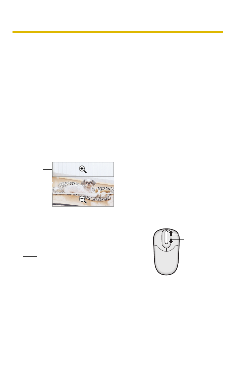
1.2.3 Zooming In and Out
This camera has 10× digital zoom feature that uses ActiveX Controls. The digital
zoom feature can be used while playing video (Motion JPEG) on the Single
Camera, Multi-Camera and Buffered Image pages. The digital zoom feature can be
operated by rotating the mouse wheel or clicking the right mouse button.
Note
• The Click to Center feature is available while zooming in or out. Images
can only be moved within the page when magnification is ×1.
• As the magnification increases, the image quality decreases.
• This feature is not available when viewing on a mobile phone.
• When camera images are buffered and transferred, the camera images
are not zoomed in and out.
Clicking the right mouse button
Moving the mouse up or down while pressing the right mouse button zooms in and
out.
Zoom in
Zoom out
Rotating the mouse wheel
On a screen, rotating the mouse wheel away from
you zooms in, and rotating it towards you zooms
out.
Note
The performance of the mouse varies
according to your OS.
Zoom in
Zoom out
31
Page 32

Operating Instructions
1.2.4 Capturing a Still Image
Still images can be saved on your PC.
1. Select an image resolution to display an image.
2. Click the Capture image button.
Capture Image Button
• The camera image opens in another window.
3. Right-click the image, and select [Save Picture As...].
• The Save as dialog box is displayed.
4. Specify a folder, enter the file name and click [Save].
• The camera image is saved in the folder.
5. Click [Close].
32
Page 33

1.2.5 Using the Operation Bar
Brightness: Adjusts image brightness in nine steps including
[STD] (Standard). Clicking [-] or [+] darkens or
brightens the image respectively.
Operating Instructions
Refresh
Interval:
Resolution: Selects [640 × 480] or [320 × 240] (default) pixels.
Image
Quality:
Sets a refresh interval. (Motion—60-second
interval)
Selects the image quality.
• [Favor Clarity] optimizes the image for good
clarity (The motion may be slow down).
• [Standard] keeps the standard quality. (default)
• [Favor Motion] optimizes the image for motion
display (The image quality may decrease).
33
Page 34
Operating Instructions
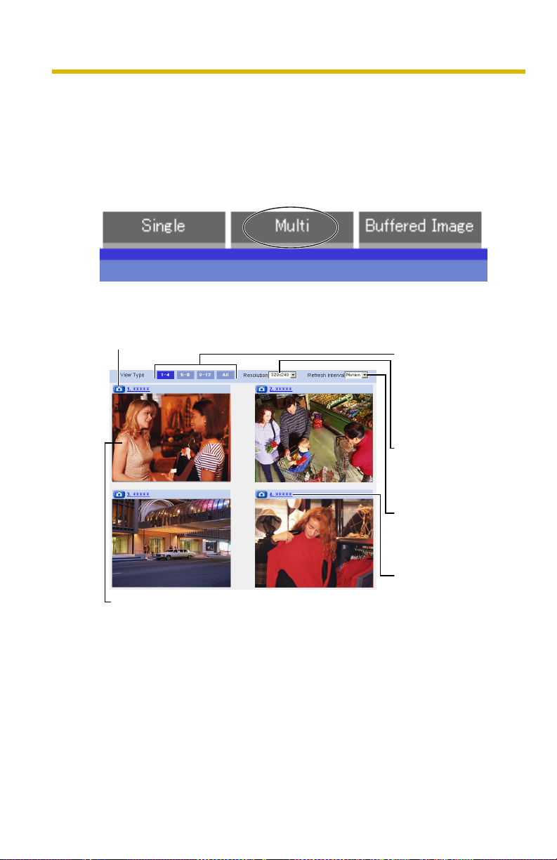
1.3 Viewing the Multi-Camera page
To view multiple cameras on the Multi-Camera page, you need to configure each
camera on the Multi-Camera Setup page (see page 106).
1. Access the camera (see page 24).
• The Top page is displayed.
2. Click the [Multi] tab at the top of the page.
• The Multi-Camera page can display up to 12 camera images.
Capture Image Button (See page 32)
Switches displayed
cameras. If you select
[All] at the View Type,
video (Motion JPEG)
cannot be displayed.
Selects [320 × 240]
(default) or [160 ×
120] pixels resolution.
The Selfcamera is registered at No. 1. (default)
3. Close the web browser.
Selects the refresh
interval (Motion—60second interval).
Clicking the camera
name displays the
Single Camera page
in another window.
34
Page 35

Operating Instructions
Note
• The digital zoom feature and the Click to Center feature can be used for
video (Motion JPEG) only.
• When selecting [All] for the View Type, all images are displayed in 160 ×
120 pixels resolution.
• 640 × 480-pixel images cannot be displayed on the Multi-Camera page.
• When viewing video (Motion JPEG), we recommend using an Ethernet
switching hub instead of a repeater hub to prevent degradation in video
display.
• Due to network congestion or the number of accesses, the refresh interval
may increase.
• If the refresh interval is too long, restrict the bandwidth on the Network
page (see page
• To reduce the data traffic, set up [Limit Continuous Motion JPEG] on the
Image Display page (see page
automatically changed to refreshing still images. Images of moving
subject are blurred or not displayed.
• When viewing 4 cameras on the Multi-Camera page, you may need 3 to 4
Mbps bandwidth. If sufficient bandwidth is not available, the refresh
interval may increase.
• The Click to Center feature can be used while using the digital zoom.
48). The refresh interval should improve.
103). The video (Motion JPEG) can be
When an image is not displayed on the Multi-Camera page
• Confirm that the global IP address is specified correctly for each camera and
that each camera is connected to the Internet. For Internet access, local IP
addresses (192.168.
Troubleshooting on the CD-ROM)
• Confirm the settings on the Multi-Camera Setup page (see page 106).
• Confirm that the web browser is not accessing a proxy server (see page 141).
. ) cannot be used. (See page 11 of
When setting [Do not permit access from guest users] or [Permit
access from guest users (mobile only)] on the Security:
Administrator page
• An authentication window is displayed when accessing the camera. Enter the
administrator's or the general user's user name and password.
• When you view images from several cameras on the Multi-Camera page, an
authentication window is displayed for each camera that has security settings
enabled. Enter the administrator's or general user's user name and password
registered for each camera.
35
Page 36

Operating Instructions
1.4 Viewing the Buffered Image page
To buffer images in the camera's internal memory, you need to set up the image
transfer settings (see page 74 or page 84). Buffered images can be viewed on this
Buffered Image page.
1. Access the camera (see page 24).
• The Top page is displayed.
2. Click the [Buffered Image] tab at the top of the page.
3. Click the trigger number.
The trigger number is displayed (see page 74 or page 84).
The trigger is displayed
(see page 74 or page 84).
36
Page 37

Operating Instructions
4. Display images by clicking buttons below.
The date and time when the images
were buffered are displayed.
Month (Sep), day (20), hour (02),
minute (58), second (15),
millisecond (120), AM/PM (PM), the
number and the total number of
frames (1/10) are displayed.
[Play]:
The buffered images are displayed in sequence.
[<Prev] or [Next>]:
The previous or next image is displayed.
[<100], [<10] or [10>], [100>]:
The 10th or 100th image before or after the current image appears.
Note
• The buffered images are displayed chronologically.
• Still images (not being played) from the Buffered Image page can be saved.
Put the cursor on the image, and right-click it. Then select [Save Picture As...].
• The maximum number of buffered images changes depending on resolution,
image quality and the specific images the camera is buffering. At 320 × 240
pixels resolution and standard quality, the camera can buffer about 250
frames.
If 3 triggers are enabled [maximum 5 triggers], the internal memory capacity
is divided into 3 sections. In this case, each trigger can buffer about 80 frames.
See page
146 for more details regarding the internal memory capacity.
• The digital zoom can be used while viewing buffered images (while playing
video [Motion JPEG]).
• The Click to Center feature can be used while using the digital zoom.
37
Page 38

Operating Instructions
1.4.1 Deleting Buffered Images
If you intend to delete images for each transfer method, click [Delete Buffered
Images] on the Trigger page (see page
Note
• If you are buffering images to the internal memory, the following operations
also delete all buffered images.
– Turning off the camera.
– Saving the Date and Time page.
– Restarting, updating firmware or resetting the camera to factory default.
– Changing the Enable/Disable settings on the Image Buffer/Transfer page
(see page 41, page 74 or page 84).
74 or page 84).
38
Page 39

Operating Instructions
1.5 Viewing Still Images on Your Mobile Phone
Still images can be viewed over the Internet from a compatible mobile phone.
Enter "http://IP address (or URL):Port Number/mobile" on a mobile phone and
press [OK].
• When the port number is set to 80 (default), it is not required.
E.g.
http:// . . . :50000/mobile
(or .viewnetcam.com:50000/mobile)
• Allow access from the Internet to access the camera from mobile phones.
• When an authentication window is displayed, enter the administrator's or
general user's user name and password.
• A still image is displayed. (Video [Motion JPEG] cannot be displayed.)
Pressing 5 will refresh the image.
160 × 120 resolution is displayed on the first access.
Pressing 0 switches the resolution to 320 × 240.
An administrator can
enable or disable the
Image Buffer/Transfer
setting from your mobile
phone (see page
41).
Displays up to 50 Logs in order of time (only for an
administrator).
Goes to the control page.
Displays the number of
new logs.
MD: Motion Detection
Displays the date and
time.
Goes to the control page.
39
Page 40

Operating Instructions
Note
• If the image is not displayed properly, try the following 2 URLs.
1. http:// IP address(or URL):Port Number/MobileH for HTML.
(or .viewnetcam.com:50000/MobileH)
2. http:// IP address(or URL):Port Number/MobileX for XHTML.
(or .viewnetcam.com:50000/MobileX)
• Some mobile phones are not compatible with Panasonic Network Cameras.
Some phones may allow viewing only on port 80, and some may not support
password authentication. See the Panasonic Network Camera support
website below for a list of mobile phones, and their level of compatibility with
the Panasonic Network Camera.
• Some mobile phones display images at a decreased size.
• If [Permit access from guest users] or [Permit access from guest users (mobile
only)] is selected, users can access mobile phone-specific screens via a
mobile phone or PC without the need for authentication.
• Only administrators can operate the Sensor log and Buffer/Transfer.
Panasonic Network Camera support website:
http://panasonic.co.jp/pcc/products/en/netwkcam/
40
Page 41

Operating Instructions
1.5.1 Enabling or Disabling the Buffer/Transfer on Your
Mobile Phone
1. Access camera images from your mobile phone, and log in as an administrator
(see page 39).
2. Select [Buffer/Transfer].
3. Select a trigger number that you want to enable or disable.
Example: Enabling the Buffer/Transfer setting (No.1).
• Selecting [Control Page] changes to the previous page.
4. Select [Save].
• Selecting [Save] enables or disables the buffer/transfer settings, and all
buffered images will be deleted.
• Selecting [Cancel] takes you back to the previous page without saving
changes.
41
Page 42

Operating Instructions
2 Using the Camera's Basic Features
2.1 Setup Page of the Camera
1. Access the camera (see page 24).
• The Top page is displayed.
Note
• When [Permit access from guest users] is set on the Security:
Administrator page, click the [Login] tab (see page
administrator.
• When users other than an administrator are accessing the camera, the
[Setup] and [Maintenance] tabs are not displayed.
2. Click the [Setup] tab at the top of the page.
(1)
(2)
(3)
(4)
(5)
(6)
(7)
(8)
70) and log in as an
(9)
(10)
(11)
(12)
(13)
(14)
(15)
42
Page 43

Operating Instructions
Basic
(1) Network Configures network settings to connect the camera to the
network (see page
45).
(2) Wireless Configure a wireless network (see page 50).
(3) UPnP Enables automatic port forwarding and creates a shortcut
to the camera (see page 53).
(4) DynamicDNS Registers with the DynamicDNS service (see page 56).
(5) Date and Time Sets the date and time, automatic time adjustment and
summer (daylight saving) time settings (see page 62).
(6) Camera Sets camera name, white balance, AC power source
frequency and color night view (see page
64).
Account
(7) Administrator*1Sets authentication and administrator security (user name
and password) (see page 66).
(8) General User*1Sets general user security (user name and password) and
access levels (see page 71).
Buffer/Transfer
(9) Tri gger Sets image buffer or transfer by timer or motion detection
(see page
74 or page 84).
(10) Motion
Detection
Sets the threshold and sensitivity for motion detection (see
page 97).
(11) Sensor Log Sets the information required to send log notifications by e-
mail (see page 100).
43
Page 44

Operating Instructions
Advanced
(12) Image Display Sets the resolution, image quality and refresh interval of the
Single Camera and Multi-Camera page, Limit Continuous
Motion JPEG setting
*1
, language and banner display (see
page 103).
(13) Multi-Camera*1Sets the camera IP address or host name, and camera
name on the Multi-Camera page (maximum 12 cameras)
(see page
106).
(14) Operation
Time
(15) Indicator
Sets the time period to display camera images (see page
108).
Sets the indicator display (see page 110).
Control
*1
If you change the [Administrator], [General User], [Multi-Camera] page settings or Limit
Continuous Motion JPEG setting, changes will not be applied to video (Motion JPEG)
viewers. Restart the camera to apply changes to all video viewers.
44
Page 45

Operating Instructions
2.2 Connecting the Camera to Your Network
The Network page offers three options to configure the camera.
• [Automatic Setup] automatically assigns an unused IP address to the camera,
and uses UPnP
• [Static] allows the user to use a specific IP address.
• [DHCP] is offered for ISPs that require this option.
1. Click [Network] on the Setup page.
2. Click a connection mode.
• See below for details of each connection mode.
3. Enter each parameter in the relevant data field.
Automatic Setup
The camera automatically obtains the network settings (subnet mask, default
gateway and DNS server address) using the router's DHCP feature. The
camera also automatically searches for an unused IP address on your
network. If you select [Yes] for Allow Access from the Internet, the camera
automatically enables port forwarding using UPnP
automatically searches for an unused port number on your network in the
order of 80, then from 50000 to 50050.
TM
(Universal Plug and Play) to configure your router.
Most common mode of setup.
Uses a static IP address.
Uses ISP DHCP server function.
TM
. In this case, the camera
• Clicking [Cancel] takes you back to the previous page without saving
changes.
45
Page 46

Operating Instructions
DHCP Setup Static Setup
• Clicking [Cancel] takes you back to the previous page without
saving changes.
4. Click [Save] when finished.
• The new settings are saved.
• When finished, the following page is displayed.
Note
The current network settings are shown on the Status page in the Maintenance
section (see page
112).
5. Click [Restart].
• The camera restarts, and the Top page is displayed.
• When the camera is restarted, all buffered images in the internal memory
are deleted.
• Checking [Yes] for [Allow Access from the Internet] on [Automatic Setup]
may not display the Top page, since the port number may change. Use the
Setup Program to access the camera.
46
Page 47

Operating Instructions
Note
If you do not know the camera IP address when setting [Automatic Setup] or
[DHCP Setup], it can be searched for by using the Setup Program (see page
134).
Setting Description
Allow Access from
the Internet
(Automatic Setup
Only)
Network
Configuration from
Setup Program
(Static/DHCP Only)
Port Number
(Static/DHCP Only)
• The Allow Access from the Internet setting automatically
configures the router's Port Forwarding setting (some
routers call it "Address Translation", "Static IP
Masquerade", "Virtual Server" or "Port Mapping"). To
enable Internet access to the camera, check [Yes]. In this
case, the camera automatically searches for an unused
port number on your network in the order of 80, then from
50000 to 50050. To disable Internet access to the camera,
check [No].
• To prohibit the Setup Program from changing the network
settings, uncheck the box.
• The default port number is 80. When you use multiple
cameras with a router on your network, each camera must
be assigned its own port number (see page
55 "2.4.2
Connecting the Camera to a Router that does not Support
UPnP™").
– Do not set the following port numbers.
FTP: 20 and 21, Telnet: 23, SMTP: 25, DNS: 53,
POP3: 110, HTTPS: 443, ICQ: 4000 and IRC: 6661—
6667.
• Enter a number between 1—65535.
• Some ISPs do not allow you to use port 80. Ask your ISP
or network administrator about which port numbers are
accessible over the Internet.
• IP address
• Subnet Mask
(Static Only)
• If your ISP or network administrator specifies an IP
address and subnet mask, enter them in each data field.
• If you use the camera on a LAN, set an IP address with the
same class as your PC (see page 133).
• Set 4 numbers (0—255) and 3 periods, such as
"192.168.0.253". Note that "0.0.0.0" and
"255.255.255.255" are not available.
47
Page 48

Operating Instructions
Setting Description
Host Name
(DHCP Only)
Default Gateway
*1
(Static/DHCP Only)
DNS Server
Address
*1
(Static/DHCP Only)
Max. Bandwidth
Usage
• If your ISP uses the DHCP function, which automatically
assigns an IP address to the camera, enter the ISPassigned host name. (The host name may be used as an
authentication.)
• Enter ASCII characters for the host name (see page 145).
Note that [Space], ["], ['], [&], [<] and [>] are not available.
• If you have been assigned a Default Gateway address by
your ISP or network administrator, enter it in this data field.
• Set 4 numbers (0—255) and 3 periods, such as
"192.168.0.253". Note that "0.0.0.0" and
"255.255.255.255" are not available.
• The DNS server address is required in the following
situations:
– Transferring camera images by E-mail or FTP
– Setting cameras by their host names on the Multi-
Camera Setup page
– Using the DynamicDNS service
– Using the sensor log notification
• If you have been assigned a DNS server addresses by
your ISP or network administrator, enter them in this data
field. There are usually two addresses.
• Set 4 numbers (0—255) and 3 periods, such as
"192.168.0.253". Note that "0.0.0.0" and
"255.255.255.255" are not available.
• The bandwidth can be restricted.
• Select a maximum bandwidth from [Unlimited] to [0.1
Mbps].
Note
Set a maximum bandwidth referring to the following file
sizes. These are examples for a JPEG file of standard
image quality. File sizes may change depending on the
image quality or the brightness of the object.
160 × 120 pixels: About 3 KB (24 Kbit)
320 × 240 pixels: About 10 KB (80 Kbit)
640 × 480 pixels: About 18 KB (144 Kbit)
48
Page 49

Operating Instructions
Setting Description
Connection Type • Select [Auto Negotiation] normally. For wireless
connection, [Auto Negotiation] must be selected. If the
camera cannot be accessed, see page
9 of
Troubleshooting on the CD-ROM.
*1
If the IP address is automatically obtained from a DHCP server, this field does not need to be
set.
49
Page 50

Operating Instructions
2.3 Using Wireless LAN
Wireless communication is possible by adjusting the settings of the wireless LAN
to those of the wireless router. Take a note of the settings and save them for
reference. For more information about wireless settings, please refer to
http://panasonic.co.jp/pcc/products/en/netwkcam/
1. Click [Wireless] on the Setup page.
2. Set each parameter for Wireless Configuration.
Setting Description
SSID • The SSID must be set to match the SSID your wireless
router or wireless LAN uses. The SSID is limited to 32
characters (alpha numeric) and is case sensitive.
Communication
mode
• 802.11b: There are a lot of 802.11b-compliant products
and they are inexpensive. They are widely prevalent, so it
is likely that 802.11b will match your existing wireless
devices.
• 802.11b/g (default): This mode supports both the 802.11b
and 802.11g wireless LAN standards. It is the
communication mode that is easiest to install on your
existing wireless LAN.
• 802.11g exclusive: This mode communicates using
802.11g only. It does not support the mixed standard mode
of 802.11b/g, so it allows the use of original features of
802.11g.
*1
Even if "802.11g exclusive" is in use, the existence of other wireless devices using a 2.4
GHz bandwidth —including 802.11b wireless devices— may make the baud rate on the
802.11g slower.
*1
50
Page 51

3. Set each parameter for Encryption.
Setting Description
Cipher • Select to encrypt or not encrypt.
• To prevent unauthorized users from reading data, selecting
[WEP] is recommended.
Operating Instructions
WEPKey
Selection
• The checked WEPKey is used as the standard WEPKey.
Check the same WEPKey as the one selected for the
router.
WEPKey1—4 • Select one from [HEX, 10 characters 64 bit], [HEX, 26
characters 128 bit], [HEX, 32 characters 152 bit], [ASCII 5
characters 64 bit], [ASCII 13 characters 128 bit] or [ASCII
16 characters 152 bit].
• Selecting [WEP] at Cipher enables you to set WEPKey1—
4. One or all of the four keys can be set. Check the same
key number as set to the wireless router, and set the same
encryption as at the wireless router.
<Example>
HEX, 10 characters 64 bit : 012345abcd
HEX, 26 characters 128 bit : 0123456789abcdef012
345abcd
HEX, 32 characters 152 bit : 0123456789abcdef012
3456789abcdef
ASCII 5 characters 64 bit : 012yz
ASCII 13 characters 128 bit : 0123456uvwxyz
ASCII 16 characters 152 bit : 0123456789uvwxyz
51
Page 52

Operating Instructions
Note
• Some wireless devices do not support the WEP 152 bit encryption.
• The camera supports only open system authentication. If the wireless
router or access point is set to shared key authentication, set it to auto or
open system.
4. Click [Save] when finished.
• The new settings are saved.
• When finished, "Success!" is displayed.
5. Click [Go to Wireless configuration page].
• The Wireless page is displayed.
6. Set the switch to WIRELESS.
Note
• Encryption helps protect data within wireless LAN from third parties.
• Enter both the MAC addresses for the camera itself and the camera's
wireless module to enable the MAC address filtering feature on the
wireless router. The wireless module MAC address is one value higher
than the camera MAC address.
• It takes about 1 minute for the new settings to become effective.
• It is not possible to access the camera simultaneously by both wired and
wireless connection.
• To communicate using wireless connection, set up the camera using wired
connection and flip the switch from WIRED to WIRELESS as shown
below.
• Even if the camera is set to wired connection, it emits electrical waves for
about 5 minutes after the power has been on. During this time, the router's
wireless indicator is on or blinking. Electrical waves will stop being
transmitted after about 5 minutes.
< Side >
Switch
• When you switch from WIRED to WIRELESS or vice versa, restart the
camera. Some routers may also need to be restarted after switching.
52
Page 53

Operating Instructions
2.4 Using UPnP™ (Universal Plug and Play)
UPnPTM can automatically configure your router to make it accessible from the
Internet. In order to use this feature, your router needs to support UPnPTM, and it
must be enabled. UPnP
panasonic.co.jp/pcc/products/en/netwkcam/ and your router's manual for
details of how to enable UPnPTM. After UPnPTM is enabled on the router, set [Enable]
for auto port forwarding.
1. Click [UPnP] on the Setup page.
2. Set up UPnP.
Setting Description
TM
is disabled on most routers by default. See http://
Auto Port
Forwarding
Display Short cut
Icon in My
Network Places
• If the network setting is [Static] or [DHCP], enabling auto
port forwarding allows you to access the camera from the
Internet.
Note
If the network setting is [Automatic Setup], also enable
[Allow Access from the Internet] on the Network page (see
page 47).
• Enabling this creates a shortcut to the camera in the My
Network Places folder.
Note
To enable this feature when using Windows XP or
Windows Me, enable the UPnP
beforehand (see page
144).
TM
Windows component
53
Page 54

Operating Instructions
3. Click [Save] when finished.
• The new settings are saved.
• When finished, "Success!" is displayed.
4. Click [Go to UPnP page].
• The UPnP page is displayed.
2.4.1 Connecting the Camera to a Router that Supports
UPnP™
To allow access from the Internet with a router supporting UPnPTM, follow the
procedures shown in Getting Started.
Note
• On some routers, the UPnPTM feature is disabled by default. Enable your
router's UPnP
camera. See the Panasonic Network Camera support website at
panasonic.co.jp/pcc/products/en/netwkcam/ for details.
• If a maximum idle time is set in PPPoE or PPTP connection with your ISP,
disable it on the router. See the router manual for details.
TM
feature following the router manual before you set up the
http://
54
Page 55

Operating Instructions
2.4.2 Connecting the Camera to a Router that does not
Support UPnP™
To allow access from the Internet with a router that does not support UPnPTM, follow
the procedures below.
1. Select [Static] on the Network page.
(1) Access the camera (see page 24).
(2) Click the [Setup] tab at the top of the page.
(3) Select [Static] on the Network page.
• The Static IP Address Configuration page is displayed. Make a
note of the IP address and port number, since they are required to
enable port forwarding on the router.
Note
You must assign a unique IP address and a unique port number to
each camera in the LAN.
(4) Click [Save] without changing the settings.
(5) Click [Restart].
2. Enable port forwarding
*1
on the router.
Using the IP address and port number noted on step 1-(3), enable port forwarding on
the router. See the router manual for how to enable port forwarding.
3. Register with the DynamicDNS service.
Port Forwarding feature
The port forwarding feature is required to allow camera access from the Internet with a
router that does not support UPnPTM. It exchanges a local IP address for a global one.
Global IP address or URL
vvv.xxx.yyy.zzz:80
vvv.xxx.yyy.zzz:81
Internet
Router
Note
The IP addresses shown above may differ from those offered on your home network.
*1
"Port forwarding" may be called "Address translation", "Static IP Masquerade", "Virtual server"
or "Port mapping" in other products.
Port No.
Port Forwarding feature
192.168.0.254
*1
vvv.xxx.yyy.zzz:80 192.168.0.253:80
vvv.xxx.yyy.zzz:81 192.168.0.252:81
192.168.0.1
192.168.0.252
Port No. 81
192.168.0.253
Port No. 80
55
Page 56

Operating Instructions
2.5 Registering with the DynamicDNS service
DynamicDNS is a service that allows you to assign an easy-to-remember name to
the camera, for example, similar to your favorite website. It also allows you to easily
access the camera, even when your ISP changes the IP address. Panasonic
Communications recommends that you register with a DynamicDNS to access the
camera from the Internet. See
Viewnetcam.com service.
1. Click [DynamicDNS] on the Setup page.
• When you select [Disable] or [Viewnetcam.com] (see page 56)
• When you select [User-specified DynamicDNS] (see page 58)
When you select [Disable]
2. Click [Save].
• The DynamicDNS service is disabled.
• Clicking [Cancel] cancels your settings without saving changes.
When you select [Viewnetcam.com]
2. Click [Next].
http://www.viewnetcam.com for details about the
• Clicking [Cancel] cancels your settings without saving changes.
56
Page 57

Operating Instructions
3. Click [Save].
• Clicking [Cancel] cancels your settings without saving changes, and the
DynamicDNS window is displayed.
Setting Description
Personal
(Camera) URL
Your Account
Link
• The camera's personal URL will be displayed after you
register with the Viewnetcam.com service.
• The URL required to register with the Viewnetcam.com
service is displayed. Clicking [Your Account Link] item
name displays the Viewnetcam.com registration website.
4. Click [OK].
• When finished, "Success!" is displayed.
• The new settings are saved.
5. Click [Go to Viewnetcam.com page].
• The Viewnetcam.com page is displayed.
6. Click Your Account Link.
• The Viewnetcam.com registration website is displayed.
Note
• When the Viewnetcam.com registration website is not displayed, confirm
that the URL is displayed in the right column next to Your Account Link. If
the URL is not displayed, follow the procedures below.
1. Wait for a moment, then click [Refresh] on the web browser.
2. Confirm that your network (your PC and camera) is connected to
the Internet.
• Personal (Camera) URL is available after registering with the
Viewnetcam.com service.
• If port forwarding is not enabled or your network is not connected to the
Internet, the Viewnetcam.com service is not available.
7. Register with the Viewnetcam.com service following the instructions on the
website.
• The Viewnetcam.com page is displayed.
57
Page 58

Operating Instructions
8. Access your camera with the registered URL from the Internet (see page 24).
• When the Top page is displayed, Viewnetcam.com registration is
complete.
Note
• It may take a maximum of 30 minutes for the registered URL to work.
• If "Expired" is displayed for the Personal (Camera) URL on the
Viewnetcam.com page or for the Camera URL at Viewnetcam.com on the
Status page, restart the camera. After that, confirm that your registered
URL is displayed on the pages.
Confirming Internet access
Due to the router's specifications, the image may not be displayed even if you
access the camera from your PC on the same LAN as the camera. In this case,
try:
• Accessing from a PC on another network (see page 24)
• Accessing from your mobile phone (see page 39)
When you select [User-specified DynamicDNS]
2. Click [Next].
• Clicking [Cancel] cancels your settings without saving changes.
58
Page 59

3. Set each parameter.
• Clicking [Cancel] cancels your settings without saving changes.
• DynamicDNS information can be obtained from companies in the
DynamicDNS service industry.
Setting Description
Operating Instructions
DynamicDNS
Server URL
Input URL acquired from the DynamicDNS service industry
*1
company. Enter 1—255 characters. The URL must be started
with "http://".
Updating time Specify the updating time.
User Name
*2
Input User Name acquired from the DynamicDNS service
industry company. Enter up to 63 characters.
Password
*2
Input Password acquired from the DynamicDNS service
industry company. Enter up to 63 characters.
*1
Note that [Space] and ["] are not available.
*2
Note that ["] and [:] are not available.
4. Click [Save] after finished.
• The new settings are saved.
• When finished, "Success!" is displayed.
5. Click [Go to DynamicDNS page].
• The DynamicDNS page is displayed.
59
Page 60

Operating Instructions
Note
• It may take several minutes for the registered URL to connect.
• Some DynamicDNS services may not connect.
Confirming Internet access
Due to the router's specifications, the image may not be displayed even if you
access the camera from your PC on the same LAN as the camera. In this case,
try:
• Accessing from a PC on another network (see page 24)
• Accessing from your mobile phone (see page 39)
2.5.1 DynamicDNS Service
DynamicDNS allows you to choose an easy-to-remember address (such as
"bob.viewnetcam.com") that can be used to view images from your camera over
the Internet.
What are the advantages of DynamicDNS service?
In order to view camera images over the Internet, you need to know your camera's
global IP address. However, many Internet Service Providers (ISPs) assign their
customers a "dynamic" IP address that changes monthly, weekly, or each time they
log on. Unless you have been assigned a static IP address (an IP address that
does not change periodically) by your ISP, you may find it difficult to access your
camera over the Internet. The Viewnetcam.com service allows you to access your
camera even if your assigned global IP address changes.
60
Page 61

How the DynamicDNS service works
DynamicDNS service server
Operating Instructions
DNS
server
4.
DNS looks up
current address
3.
New address registered with
DNS server
Internet
5.
Off-site PC
Camera connection established
2.
Camera reports new address
ISP
1.
Global IP address
changes
On-site Network
Camera
1. Your ISP assigns a global IP address to your Internet access account that
changes periodically. This is the address needed to access the camera over
the Internet.
2. When your ISP-assigned global IP address changes, your camera
automatically notifies the DynamicDNS service server of the new address in
the DynamicDNS. The camera notifies the DynamicDNS service server of the
new address in DynamicDNS in the following cases.
– When starting the camera
– When an update interval time has been set
– When clicking the [Save] button
3. The DynamicDNS server contacts the Domain Name System (DNS) server
and registers your new global IP address to your chosen DynamicDNS
address (such as "bob.viewnetcam.com").
4. When you enter your DynamicDNS address in your web browser while away
from home or the office, the DNS server looks up the global IP address
assigned to your DynamicDNS address.
5. The DNS server finds your current global IP address and allows you to connect
to your camera.
Note
• Ask your ISP about what type of IP address you are using.
• Some ISPs assign you a local IP address. In this case, the DynamicDNS
service cannot be used.
• If the camera is using a port number other than 80, the port number must
be specified at the end of the DynamicDNS URL. For example:
– Using port 80: http://(Cameraname).viewnetcam.com
– Using any other port: http://(Cameraname).viewnetcam.com:Port
Number
61
Page 62

Operating Instructions
2.6 Setting the Date and Time
The Date and Time page allows you to set and confirm the date and time. The date
and time are used for the settings of the trigger setting, sensor log, operation time
and Buffered Image page.
Note
Saving a new date and time deletes all buffered images on the internal
memory.
1. Click [Date and Time] on the Setup page.
2. Set each parameter.
• Set [Automatic Time Adjustment] to synchronize the time automatically
with an NTP server.
• Clicking [Cancel] cancels your settings without saving changes.
62
Page 63

Setting Description
Operating Instructions
Time Setting
Automatic Time
Adjustment
Adjust Clock for
Daylight Saving
Time
• Set the date and format (AM/PM or 24 H). The interface and available
values depend on the format. The date and time are used for the
settings of the trigger setting, sensor log, operation time and Buffered
Image page. Note that the format for the subject and file name of Emails by E-mail or FTP transfer can only be 24 h.
• NTP (Network Time Protocol) server synchronizes the camera's
internal clock automatically every day. Check the box to enable it.
• Set the NTP server IP address. Set 4 numbers (0—255)
and 3 periods, such as "192.168.0.253". Note that "0.0.0.0"
and "255.255.255.255" are not available. Set a host name
(1—255 characters). Note that [Space], ["], ['], [&], [<] and
[>] are not available.
• Select your time zone.
Note
The camera will not synchronize to the NTP server if there
is more than a 1 hour difference between the NTP server
time and the camera's current time. This is to protect the
camera's time setting from fraudulent NTP server
tampering, incorrect time information, etc.
• During summer time, the internal clock is turned forward an
hour. The clock will shift one hour forward at the set time
on the Start Day, and move back one hour at the set time
on the End Day. Check the box to enable it.
Note
An "s" is inserted between the date and time of the time stamp
when this feature is enabled. The time stamp is printed on
images transferred by the Image Transfer feature.
3. Click [Save] when finished.
• The new settings are saved.
• When finished, "Success!" is displayed.
4. Click [Go to Date and Time page].
• The Date and Time page is displayed.
Note
Date and time settings become incorrect depending on the length of time the
camera is turned on and its internal temperature. Using the Automatic Time
Adjustment is recommended.
63
Page 64
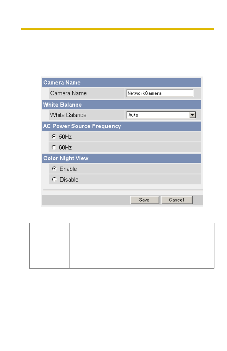
Operating Instructions
2.7 Changing Camera Settings
The Camera page allows you to set the camera name, white balance, AC power
source frequency and color night view.
1. Click [Camera] on the Setup page.
2. Set each parameter.
• Clicking [Cancel] cancels your settings without saving changes.
Setting Description
Camera Name
• The camera name is displayed on the Single Camera page.
• Enter ASCII characters (see page 145) or characters from
other languages (1—15 characters for a 1-byte character
and 1—7 characters for a 2-byte character). Note that
[Space], ["], ['], [&], [<], and [>] are not available.
64
Page 65

Setting Description
White Balance Select from the following options.
• Auto (default) — Automatic adjustment
• Fixed Indoor — Electric bulb (2800 K)
Operating Instructions
AC Power
Source
Frequency
Color Night
View
• Fixed Fluorescent
(White)
• Fixed Fluorescent
(Daylight)
• Fixed Outdoor — Solar light (6000 K)
— White (3600 K)
— Daylight (4000 K)
Note
The kelvin (symbol: K) is the standard unit for color
temperature.
• This setting may correct flickering caused by power line
frequency.
– 50 Hz (default)
–60 Hz
• In the color night view mode, the camera image becomes
brighter in a low illuminance. The camera image returns to
normal operation in a bright location.
• If you enable the color night view mode, refresh interval
may increase.
• Subjects that are moving in low illumination may be
blurred, not distinguished, or not displayed.
Note
When the camera transmits a dark scene, the camera
image may become white, or horizontal lines may be
displayed on the screen. This is one of the characteristics
of a CMOS sensor. This is not a malfunction.
3. Click [Save] when finished.
• The new settings are saved.
• When finished, "Success!" is displayed.
4. Click [Go to Camera page].
• The Camera page is displayed.
65
Page 66

Operating Instructions
3 Registering Users
3.1 Changing the Authentication Setting and Administrator User Name and Password
The Security: Administrator page allows you to change authentication, and the
administrator's user name and password. An authentication window allows
registered users to access the camera.
Note
• If you access the camera for the first time, the window for setting the
administrator's user name and password is displayed. Make a note of the user
name and password so that you will not forget them.
• The user name and password should be secured at your own responsibility.
Pay attention to the following points.
– Set a user name and password with as many characters as possible.
– Change the password regularly.
• Setting [Permit access from guest users] (permitting access without a User
Name or Password) or [Permit access from guest users (mobile only)]
(permitting access without a User Name or Password) at General
Authentication risks the images being viewed by third parties. Control the
contents of the images accordingly.
IMPORTANT
• It is important to limit access to the camera by use of a unique User Name and
a secret Password. Since the camera is accessed through the Internet it is
possible that the camera could be accessed by unknown individuals, including
those who are commonly known as "crackers" to whom you do not want to
allow access. The use of a unique User Name and a Password known only to
you will help insure that only authorized individuals are given access to the
camera. You have the option of proceeding without a User Name and
Password, but it is strongly recommended that you utilize these protections.
1. Click [Administrator] on the Setup page.
66
Page 67

2. Set each parameter.
• Clicking [Cancel] cancels your settings without saving changes.
Setting Description
Operating Instructions
General
Authentication
Authentication has 3 phases.
• If you set [Permit access from guest users], the camera
does not display the authentication window in camera
access. All guest users can view images without a user
name and password.
Note
If you set [Permit access from guest users], [Login] tab is
displayed at the top of the page. After you log in as an
administrator (see page 70), the Setup page and the
Maintenance page can be accessed.
• If you set [Permit access from guest users (mobile only)],
an authentication window is not displayed even if you
access the mobile phone page. All guest users can view
images without a user name and password.
• If you set [Do not permit access from guest users], an
authentication window is displayed to access the camera.
Users must enter the user name and password.
67
Page 68

Operating Instructions
Setting Description
User Name/
Password
• User Name (6 to 15 characters): Enter the user name.
• Password (6 to 15 characters): Enter the password.
Note
The password must be different from the user name.
• Retype Password: Reenter the password.
• Enter ASCII characters (see page 145). Note that [Space],
["], ['], [&], [<], [>] and [:] are not available.
Note
• When setting authentication, set the user name and password, and save
them.
• When users other than an administrator are accessing the camera, the
[Setup] and [Maintenance] tabs will not be displayed.
• The user name and password are case sensitive.
3. Click [Save] when finished.
• The new settings are saved.
• When finished, "Success!" is displayed.
4. Click [Go to Security: Administrator page].
• The Security: Administrator page is displayed.
Note
When the user name and password have been changed, the camera displays
an authentication window. Enter the user name and password, and click [OK].
68
Page 69

Operating Instructions
Administrator/General Users/Guest Users
The camera has 3 user levels (administrator, general users and guest users).
Items Administrator General Users Guest Users
User Name and
Password
Number of Users 1 50 —
Accessible Pages All Pages Pages Except For
Access Level All Operations Access level can
Required Required Not Required
Pages Except For
Setup and
Maintenance page
be set for each
general user (see
page
71).
Setup and
Maintenance page
Access level can
be set for guest
users (see page
71).
Note
Guest users mean unregistered users. Set [Permit access from guest users]
or [Permit access from guest users (mobile only)] on the Security:
Administrator page (see page 66) to allow access from guest users.
69
Page 70

Operating Instructions
3.2 Logging in to the Camera
If you set [Permit access from guest users] on the Security: Administrator page,
[Login] tab is displayed at the top of the page. After you log in as an administrator,
the Setup page and the Maintenance page can be accessed.
1. Click [Login] tab at the top of the page.
2. Check a login mode, and click [Login].
Note
The authentication window is displayed. Enter the user name and password
set for General Users or Administrator.
3. Enter a valid user name and password according to the Login mode selected
in step 2, and click [OK].
70
Page 71

Operating Instructions
3.3 Creating, Modifying or Deleting General Users
The General User page allows you to create, modify or delete general users. Up to
50 general users can be registered. The access level is set for each general user.
If you set [Permit access from guest users] or [Permit access from guest users
(mobile only)] on the Security: Administrator page, the access level can be set for
guest users.
Note
For general users, the Setup and Maintenance tabs are not displayed.
1. Click [General User] on the Setup page.
2. To create a general user, click [Create].
• When setting [Do not permit
access from guest users]
• To change the settings of general users or guest users, select their
name and click [Modify]. The modification page is displayed.
• To delete a general user, select the name and click [Delete]. The
confirmation page is displayed.
• When setting [Permit access
from guest users] or [Permit
access from guest users
(mobile only)]
71
Page 72

Operating Instructions
3. Set each parameter.
• Settings for general users • Settings for guest users
• Clicking [Cancel] takes you back to the previous page without
saving changes.
Setting Description
User ID List • Up to 50 general users can be registered.
• The list is used to modify or delete general user settings.
User Name/
Password
• User Name (6 to 15 characters): Enter the user name.
• Password (6 to 15 characters): Enter the password.
Note
The password must be different from the user name.
• Retype Password: Reenter the password.
• Enter ASCII characters (see page 145). Note that [Space],
["], ['], [&], [<], [>] and [:] are not available.
Access Level An access level is set for each general user.
• Level 1 : Only the camera images can be viewed.
• Level 2 : The camera images can be viewed and the
brightness can be adjusted.
4. Click [Save] when finished.
• The new settings are saved.
• When finished, "Success!" is displayed.
5. Click [Go to General User page].
• The General User page is displayed.
72
Page 73

Operating Instructions
4 Buffering or Transferring Images
4.1 Procedures of Buffering or Transferring Images
The procedures from this page to page 96 described the settings of the image
buffer or transfer. See the procedures below to understand the general outline of
the settings.
Buffer/Transfer by Timer (Page 74)
Time Setting
Image Setting
Image Buffer Frequency Setting
Transfer Method
Select one from the lists.
• No Transfer, No Memory Overwrite
• No Transfer, Memory Overwrite
• FTP
• E-mail
Save the settings to complete.
Buffer/Transfer by Motion
Detection Signal (Page 84)
Time Setting
Image Setting
Image Buffer Frequency Setting
Transfer Method
Select one from the lists.
• No Transfer, No Memory Overwrite
• No Transfer, Memory Overwrite
• FTP
• E-mail
E-mail Notification
When Triggered Setting
Save the settings to complete.
Changing Motion Detection Sensitivity
(Page 97)
Notifying the Sensor Log
(Page 100)
73
Page 74

Operating Instructions
4.2 Buffering or Transferring Images by Timer
The Trigger page allows you to enable image buffer/transfer by E-mail or FTP.
1. Click [Trigger] on the Setup page.
2. Click a No. to enable buffer/transfer.
3. Check [Enable Image Buffer/Transfer], and select [Timer] for the trigger, and
click [Next>].
Note
• Click [Delete Buffered Images] to delete images already buffered.
• Click [Save] to save the settings. The buffered images will be deleted.
• Clicking [Cancel] takes you back to the Trigger page without saving
changes.
Setting Description
Enable Image
Buffer/Transfer
• Check the box to enable the Trigger setting. Uncheck the
box to disable it.
74
Page 75

Operating Instructions
Setting Description
Trigger • Selecting [Timer] enables the camera to buffer/transfer
images during the specified date and time by timer.
• Selecting [Motion Detection] enables the camera to buffer/
transfer images when the motion is detected during the
specified date and time.
4. Set the time, and click [Next>].
Note
The timer works by an internal clock. Set the date and time before using timer
buffer/transfer (see page
• Clicking [<Back] takes you back to the previous page.
• Clicking [Cancel] takes you back to the Trigger page without saving
changes.
Setting Description
62).
Day of the week • Check the box to enable the day. Uncheck the box to
disable it.
Active Time of
Trigger
• To set a trigger time, check the time option and set a time
period. Check the [Always] option if you are not specifying
a time period.
5. Set the image settings, and click [Next>].
• Clicking [<Back] takes you back to the previous page.
• Clicking [Cancel] takes you back to the Trigger page without saving
changes.
75
Page 76

Operating Instructions
Setting Description
Image
Resolution
Image Quality • Select the image quality.
• Select an image resolution (640 × 480, 320 × 240 (default)
or 160 × 120 pixels) for the buffer/transfer.
[Favor Clarity] optimizes for good quality.
[Standard] offers standard quality. (default)
[Favor Motion] optimizes for enhanced motion.
[Mobile Phone] is for a transfer to a mobile phone.
Note
640 × 480 pixels cannot be set for a transfer to a mobile
phone.
6. Set the image buffer frequency, and click [Next>].
Note
Due to the network environment, object and the number of simultaneous
accesses, the camera may not record the number of images that you set. In
this case, set the image buffer frequency longer.
• Clicking [<Back] takes you back to the previous page.
• Clicking [Cancel] takes you back to the Trigger page without saving
changes.
Setting Description
Image Buffer
Frequency
• Select an image buffer frequency to buffer or transfer the
image. (1 image per hour—15 images per second)
76
Page 77

Operating Instructions
7. Select the transfer method, and click [Next>].
• Clicking [<Back] takes you back to the previous page.
• Clicking [Cancel] takes you back to the Trigger page without saving
changes.
Note
If you transfer images by E-mail or FTP, confirm that the default gateway and
DNS server addresses are assigned correctly (see page
Setting Description
45).
No Transfer, No
Memory
Overwrite
No Transfer,
Memory
Overwrite
FTP • The camera transfers the image to an FTP server (see
E-mail • The camera transfers the image by E-mail (see page 80).
• If the internal memory is full, the camera stops buffering.
• If the internal memory is full, the camera deletes the old
images, and continues to buffer the image.
page 78).
77
Page 78
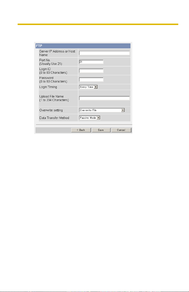
Operating Instructions
When you set [FTP] for Transfer Method
Select [FTP], and click [Next>]. The following page is displayed.
• Clicking [<Back] takes you back to the previous page.
• Clicking [Cancel] takes you back to the Trigger page without saving
changes.
78
Page 79

Setting Description
Operating Instructions
Server IP
Address or
Host Name
• If you set a server IP address, set 4 numbers (0—255) and 3
periods, such as "192.168.0.253". Note that "0.0.0.0" and
*1
"255.255.255.255" are not available. Or set a host name (1—
255 characters).
Por t No. • Enter a number (1—65535). Usually set to 21.
Login ID
*2
• If your ISP requires a login ID, set it (0—63 characters).
Password*2• If your ISP requires a password, set it (0—63 characters).
Login Timing • Select the login setting for the FTP server. If you set [One
Time] and the image buffer frequency value is set within 1
minute, the camera logs in to the server only once. This can
reduce transfer time.
Upload File
*1
Name
• Set a file name on the FTP server to receive the transferred
files. Enter 1—234 characters. Entering "\" creates directories
for a file. (E.g. NetworkCamera\image)
Overwrite
Setting
• Selecting [Overwrite File] overwrites the image on the server
with a newer image. Selecting [Save as New File with Time
Stamp] saves the image attaching time stamps on the file
name, and the images are not overwritten.
(E.g. image20050101093020500.jpg) The underlined
numbers mean "9h30min20s500ms on January 1, 2005". The
letter "s" is inserted after the day when referring to a summer
time zone.
Data
Tr an s fe r
• Select [Passive Mode] normally. If the transfer does not work,
select [Active Mode] and check the operation.
Method
*1
Note that [Space], ["], ['], [&], [<] and [>] are not available.
*2
Note that ["] is not available.
79
Page 80

Operating Instructions
When you set [E-mail] for Transfer Method
Select [E-mail], and click [Next>]. The following page is displayed.
• Clicking [<Back] takes you back to the previous page.
• Clicking [Cancel] takes you back to the Trigger page without saving
changes.
Note
• The camera works only with an SMTP (Simple Mail Transfer Protocol) server.
It does not work with mail servers like "Hotmail
• The date and time (24-h format) is automatically attached to the subject on the
E-mail. The file name is "image.jpg".
E.g. When the "camera" is entered on the subject:
"camera:20050101093020500".
The underlined numbers mean "9 h 30 min 20 s 500 ms on January 1, 2005".
The letter "s" is inserted after the day when referring to a summer time zone.
®
" that use a web browser.
80
Page 81

Setting Description
Operating Instructions
SMTP Server IP
Address or Host
*1
Name
• If you set a server IP address, set 4 numbers (0—255) and
3 periods, such as "192.168.0.253". Note that "0.0.0.0" and
"255.255.255.255" are not available. Or set a host name
(1—255 characters).
Por t No. • Enter a number (1—65535). Usually set to 25.
Reply E-mail
Address
*2
Destination Email Address
• Set the sender's E-mail address. We recommend you to
set the administrator's E-mail address.
• Set up to 3 destination E-mail addresses.
*2
1—3
*2
Subject
• Enter a subject with ASCII characters (see page 145) or
characters from other languages (0—44 characters for a
1-byte character and 0—22 characters for a 2-byte
character).
*2
Tex t
• Enter text with ASCII characters (see page 145) or
characters from other languages (0—63 characters for a
1-byte character and 0—31 characters for a 2-byte
character). Note that [end-of-line] key is not available.
81
Page 82

Operating Instructions
Setting Description
How to
authenticate
You can select the authentication method: [No authentication],
[POP before SMTP authentication] and [SMTP authentication].
POP server authentication may be required by your ISP. In
that case, set POP before SMTP authentication.
• No authentication: No authentication when sending an e-
mail.
• POP before SMTP authentication: Some SMTP servers
that send e-mails do not have an authentication feature.
Therefore, the camera uses the authentication of a POP
server that receives e-mails, before sending e-mails.
– POP3 Server
IP Address or
Host Name
If you set a server IP address, set 4
numbers (0—255) and 3 periods, such as
*1
"192.168.0.253". Note that "0.0.0.0" and
:
"255.255.255.255" are not available. Or
set a host name (1—255 characters).
– Port No.: Enter a number (1—65535). Usually set
to 110.
– Login ID*2: If your ISP requires a login ID to log in to
a POP3 server, set it (1—63 characters).
– Password*2: If your ISP requires a password to log in
to a POP3 server, set it (0—63
characters).
• SMTP authentication: Users are authenticated by user
name and password on the SMTP server. Your ISP must
support the SMTP authentication. Only the LOGIN and
PLAIN authentication mechanisms are supported.
– Login ID*2: If your ISP requires a login ID to log in to
an SMTP server, set it (1—63
characters).
– Password*2: If your ISP requires a password to log in
to an SMTP server, set it (0—63
characters).
*1
Note that [Space], ["], ['], [&], [<] and [>] are not available.
*2
Note that ["] is not available.
82
Page 83

8. Confirm the settings, and click [Save].
• The new settings are saved.
• When finished, "Success!" is displayed.
9. Click [Go to Trigger page].
• The Trigger page is displayed.
Note
• If you are buffering images to the internal memory, the following
operations also delete all buffered images.
– Turning off the camera.
– Saving the Date and Time page.
– Restarting, updating firmware or resetting the camera to factory
default.
Operating Instructions
83
Page 84

Operating Instructions
4.3 Buffering or Transferring Images by Motion Detection Signal
The Trigger page allows you to enable image buffer/transfer by E-mail or FTP.
Note
• The level of motion detection depends on resolution, image quality, and
the object being viewed. Check the level by performing motion detection
recording. (See page 97)
• Enabling Motion Detection delays the frame rate of the camera.
• A change to light or wind conditions may detect motions accidentally.
• Motion Detection may not work in dark areas.
• Objects moving fast may not be detected.
1. Click [Trigger] on the Setup page.
2. Click a No. to enable buffer/transfer.
3. Check [Enable Image Buffer/Transfer], select [Motion Detection] for the trigger,
and click [Next>].
84
Page 85

Operating Instructions
Note
• Click [Delete Buffered Images] to delete images already buffered.
• Click [Save] to save the settings. The buffered images will be deleted.
• Clicking [Cancel] takes you back to the Trigger page without saving
changes.
Setting Description
Enable Image
Buffer/Transfer
Trigger • Selecting [Timer] enables the camera to buffer/transfer
• Check the box to enable the Trigger setting. Uncheck the
box to disable it.
images during the specified date and time by timer.
• Selecting [Motion Detection] enables the camera to buffer/
transfer images when the motion is detected during the
specified date and time.
4. Set the time, and click [Next>].
Note
The timer works by an internal clock. Set the date and time before using timer
buffer/transfer (see page
• Clicking [<Back] takes you back to the previous page.
• Clicking [Cancel] takes you back to the Trigger page without saving
changes.
Setting Description
Day of the week • Check the box to enable the day. Uncheck the box to
62).
disable it.
Active Time of
Trigger
• To set a trigger time, check the time option and set a time
period. Check [Always] if you are not specifying a time
period.
85
Page 86

Operating Instructions
5. Set the image settings, and click [Next>].
• Clicking [<Back] takes you back to the previous page.
• Clicking [Cancel] takes you back to the Trigger page without saving
changes.
Setting Description
Image
Resolution
Image Quality • Select the image quality.
• Select an image resolution (640 × 480, 320 × 240 (default)
or 160 × 120 pixels) for the buffer/transfer.
[Favor Clarity] optimizes for good quality (The motion may
be slow down).
[Standard] offers standard quality. (default)
[Favor Motion] optimizes for enhanced motion (The image
quality may decrease).
[Mobile Phone] is for a transfer to a mobile phone.
Note
640 × 480 pixels cannot be set for a transfer to a mobile
phone.
86
Page 87
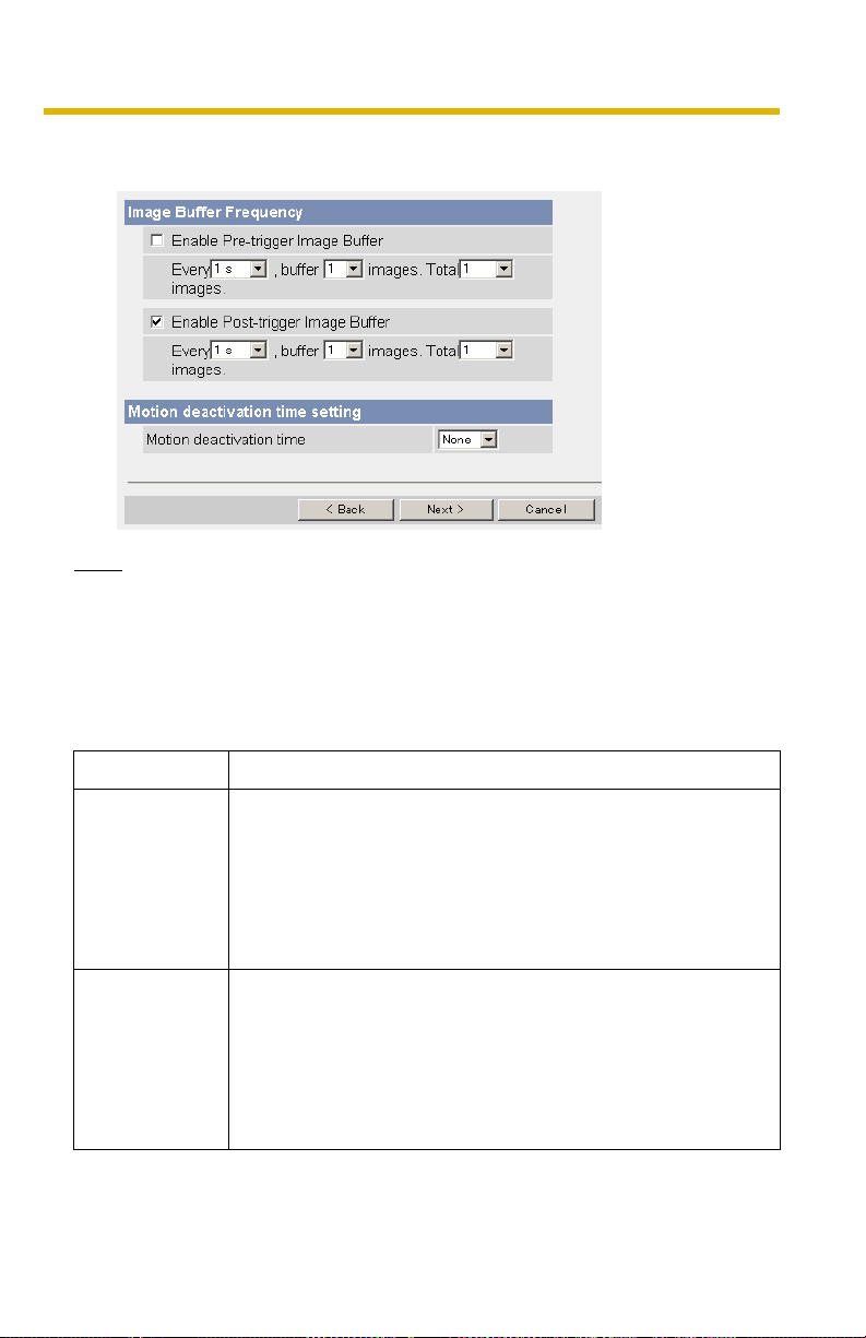
Operating Instructions
6. Set the image buffer frequency and the Motion deactivation time, and click
[Next>].
Note
Due to the network environment, object and the number of simultaneous
accesses, the camera may not record the number of images that you set. In
this case, set the image buffer frequency longer.
• Clicking [<Back] takes you back to the previous page.
• Clicking [Cancel] takes you back to the Trigger page without saving
changes.
Setting Description
Enable Pretrigger Image
Buffer
Enable Posttrigger Image
Buffer
• Check the box to enable the setting. The camera buffers or
transfers the image right before the motion detection signal
is detected.
• Set an interval, number of images to buffer and total
number (see page
may not match the total number due to memory capacity,
image resolution, image quality or what object you view.
• Check the box to enable the setting. The camera buffers or
transfers the image right after the motion detection signal
is detected.
• Set an interval, number of images to buffer and total
number (see page
may not match the total number due to memory capacity,
image resolution, image quality or what object you view.
146). The number of buffered images
146). The number of buffered images
87
Page 88

Operating Instructions
Setting Description
Motion
deactivation
time
• Set the length of time during which the Motion Detection
cannot be triggered after saving images temporarily or
transmitting them. This function is recommended to
prevent sending too many E-mails to a mobile phone.
• After detecting motions, the camera does not detect
motions during motion deactivation time, so some images
may not be captured.
Note
The internal memory cannot buffer images during motion
deactivation time. Because of this, images taken before
detection are not saved in internal memory, and so cannot
be received. Depending on the settings for image buffer/
transfer, even if it is set to, for example, take "1 image per
second, and store 10 images, before detection", since the
images are not stored in internal memory, if the Motion
Detection detects something directly after the end of
motion deactivation time, the images may not be saved.
Ten seconds after the end of motion deactivation time,
images can be received as specified in the settings (see
96).
page
88
Page 89

Operating Instructions
7. Select the transfer method, and click [Next>].
• Clicking [<Back] takes you back to the previous page.
• Clicking [Cancel] takes you back to the Trigger page without saving
changes.
Note
If you transfer images by E-mail or FTP, confirm that the default gateway and
DNS server addresses are assigned correctly (see page
Setting Description
45).
No Transfer, No
Memory
Overwrite
No Transfer,
Memory
Overwrite
FTP • The camera transfers the image to an FTP server (see
E-mail • The camera transfers the image by E-mail (see page 92).
• If the internal memory is full, the camera stops buffering.
• If the internal memory is full, the camera deletes the old
images, and continues to buffer the image.
page 90).
89
Page 90

Operating Instructions
When you set [FTP] for Transfer Method
Select [FTP], and click [Next>]. The following page is displayed.
• Clicking [<Back] takes you back to the previous page.
• Clicking [Cancel] takes you back to the Trigger page without saving
changes.
90
Page 91

Setting Description
Operating Instructions
Server IP
Address or
Host Name
• If you set a server IP address, set 4 numbers (0—255) and 3
periods, such as "192.168.0.253". Note that "0.0.0.0" and
*1
"255.255.255.255" are not available. Or set a host name (1—
255 characters).
Por t No. • Enter a number (1—65535). Usually set to 21.
Login ID
*2
• If your ISP requires a login ID, set it (0—63 characters).
Password*2• If your ISP requires a password, set it (0—63 characters).
Login Timing • Select the login setting for the FTP server. If you set [One
Time] and the image buffer frequency value is set within 1
minute, the camera logs in to the server only once. This can
reduce transfer time.
Upload File
*1
Name
• Set a file name on the FTP server to receive the transferred
files. Enter 1—234 characters. Entering "\" creates directories
for a file. (E.g. NetworkCamera\image)
Overwrite
Setting
• Selecting [Overwrite File] overwrites the image on the server
with a newer image. Selecting [Save as New File with Time
Stamp] saves the image attaching time stamps on the file
name, and the images are not overwritten.
(E.g. image20050101093020500.jpg) The underlined
numbers mean "9h30min20s500ms on January 1, 2005". The
letter "s" is inserted after the day when referring to a summer
time zone.
Data
Tr an s fe r
• Select [Passive Mode] normally. If the transfer does not work,
select [Active Mode] and check the operation.
Method
*1
Note that [Space], ["], ['], [&], [<] and [>] are not available.
*2
Note that ["] is not available.
91
Page 92

Operating Instructions
When you set [E-mail] for Transfer Method
Select [E-mail], and click [Next>]. The following page is displayed.
• Clicking [<Back] takes you back to the previous page.
• Clicking [Cancel] takes you back to the Trigger page without saving
changes.
92
Page 93

Operating Instructions
Note
• The camera works only with an SMTP (Simple Mail Transfer Protocol)
server. It does not work with mail servers like "Hotmail" that use a web
browser.
• The date and time (24-h format) is automatically attached to the subject
on the E-mail. The file name is "image.jpg".
E.g. When the "camera" is entered on the subject:
"camera:20050101093020500".
The underlined numbers mean "9 h 30 min 20 s 500 ms on January 1,
2005". The letter "s" is inserted after the day when referring to a summer
time zone.
Setting Description
SMTP Server IP
Address or Host
*1
Name
• If you set a server IP address, set 4 numbers (0—255) and
3 periods, such as "192.168.0.253". Note that "0.0.0.0" and
"255.255.255.255" are not available. Or set a host name
(1—255 characters).
Por t No. • Enter a number (1—65535). Usually set to 25.
Reply E-mail
Address
*2
Destination Email Address
• Set the sender's E-mail address. We recommend you to
set the administrator's E-mail address.
• Set up to 3 destination E-mail addresses.
*2
1—3
*2
Subject
• Enter a subject with ASCII characters (see page 145) or
characters from other languages (0—44 characters for a 1byte character and 0—22 characters for a 2-byte
character).
Tex t*2 • Enter text with ASCII characters (see page 145) or
characters from other languages (0—63 characters for a 1byte character and 0—31 characters for a 2-byte
character). Note that [end-of-line] key is not available.
93
Page 94

Operating Instructions
Setting Description
How to
authenticate
You can select the authentication method: [No authentication],
[POP before SMTP authentication] and [SMTP authentication].
POP server authentication may be required by your ISP. In
that case, set POP before SMTP authentication.
• No authentication: No authentication when sending an e-
mail.
• POP before SMTP authentication: Some SMTP servers
that send e-mails do not have an authentication feature.
Therefore, the camera uses the authentication of a POP
server that receives e-mails, before sending e-mails.
– POP3 Server
IP Address or
Host Name
If you set a server IP address, set 4
numbers (0—255) and 3 periods, such as
*1
"192.168.0.253". Note that "0.0.0.0" and
:
"255.255.255.255" are not available. Or
set a host name (0—255 characters).
– Port No.: Enter a number (1—65535). Usually set
to 110.
– Login ID*2: If your ISP requires a login ID to log in to
a POP3 server, set it (1—63 characters).
– Password*2: If your ISP requires a password to log in
to a POP3 server, set it (0—63
characters).
• SMTP authentication: Users are authenticated by user
name and password on the SMTP server. Your ISP must
support the SMTP authentication. Only the LOGIN and
PLAIN authentication mechanisms are supported.
– Login ID*2: If your ISP requires a login ID to log in to
an SMTP server, set it (1—63
characters).
– Password*2: If your ISP requires a password to log in
to an SMTP server, set it (0—63
characters).
*1
Note that [Space], ["], ['], [&], [<] and [>] are not available.
*2
Note that ["] is not available.
94
Page 95

Operating Instructions
8. After you confirm the settings and click [Next>], set E-mail notification and click
[Next>].
• If you select [Enable], the E-mail Notification When Triggered page is
displayed. Enter the settings referring to page
Setting Description
Disable • The camera does not send an E-mail notification when
buffering or transferring images.
Enable • The camera sends an E-mail notification up to 3
destinations when buffering or transferring images.
92 — page 94.
9. Click [Save] after confirming the settings.
• The new settings are saved.
• When finished, "Success!" is displayed.
95
Page 96

Operating Instructions
10. Click [Go to Trigger page].
• The Trigger page is displayed.
Note
• If you set a short interval when transferring to a mobile phone, many E-
mails will be sent, which may lead to a large phone bill. Therefore, we
recommend you to set a long interval. 1 image per minute frequency is
recommended.
• Motion Detection transfer stops operating until after the camera finishes
all transfers. For example, if the camera transfers 3 images per minute and
6 images in total by setting 1 minute for motion deactivation time, the
sensor will follow the pattern below.
120 seconds
1 minute
1st 2nd 3rd 4th 5th 6th
Detectable Undetectable
Undetectable
Motion
deactivation time
A Motion Detection signal is detected.
• If you are buffering images to the internal memory, the following
operations also delete all buffered images.
– Turning off the camera.
– Saving the Date and Time page.
– Restarting, updating firmware or resetting the camera to factory
default.
Detectable
96
Page 97

Operating Instructions
4.4 Setting the Motion Detection
The Motion Detection page allows you to adjust the sensitivity of Motion Detection.
Threshold: If the threshold is set low, this function detects nearly all movements.
Sensitivity: If you set sensitivity high, the amplitude of the motion detection bar gets
jumpy.
1. Click [Motion Detection] on the Setup page.
2. Click the Motion Detection bar in Threshold to set the threshold level.
3. Click the Motion Detection bar in Sensitivity to set the sensitivity level.
4. Click [Save] to save the settings.
• Clicking [Cancel] cancels your settings without saving changes.
5. Click [Go to Motion Detection page].
• The Motion Detection page is displayed.
Setting Description
Threshold • Adjusts the threshold for Motion Detection. As the value is
set lower, the sensor will detect motions of smaller
changes.
Sensitivity • Adjusts the sensitivity for Motion Detection. As the value is
set higher, the amplitude of the Motion Detection bar will
become greater.
Preview
Display the current threshold and detection level.
• The threshold is the line between the green and red bar.
• The detection level is the line between the dark red and light red color.
• The Threshold and Sensitivity settings are enabled after saving, and
reflected in preview.
97
Page 98

Operating Instructions
Threshold
Note
No responsibility will be taken by our company with respect to consequences
resulting from the use of the Motion Detection feature. The Motion Detection
feature is not suitable and not recommended for uses that require a high
reliability constantly such as surveillance, etc.
What is the threshold?
The threshold is the minimum value for the camera to detect motions on the image
during the motion detection buffering. Setting the threshold lower allows subtler
changes to be detected. Setting the threshold higher allows only bigger changes
that might occupy half the image to be detected.
98
Page 99

Operating Instructions
What is the sensitivity?
The sensitivity is the level of brightness detected as motion by the camera. A high
sensitivity setting enables the camera to detect slight brightness changes. Lower
the sensitivity to make the camera detect only big brightness changes.
Threshold
setting is
displayed.
The detection level exceeds the
threshold when motions are
detected.
Note
Lowering the threshold and increasing sensitivity enable the camera to easily
detect slight movements on parts of the image.
Note
• Motion Detection is activated by changes in the outline of objects and
brightness changes. This feature is designed to alleviate false detections
due to overall brightness changes caused by sunlight. But in some cases,
the camera may falsely detect rapid brightness changes by artificial light
such as fluorescent light. In other cases, the motion detection function on
the Network Camera Recorder may detect objects and brightness
changes. The way to detect motion differs between the camera and the
Network Camera Recorder. Additionally, if the object's color is similar to
the color of the background, motion can be hard to detect.
• The detection level depends on the object, resolution, or image quality.
Confirm the condition on the Preview window following the procedure
above.
99
Page 100

Operating Instructions
4.5 Setting Sensor Log Notification
A sensor log sent once a day at a specified time can be checked. To enable Sensor
Log, set Motion Detection for Trigger Setting and check [Enable].
1. Click [Sensor Log] on the Setup page.
• When enabling the image/buffer transfer setting and selecting Motion
Detection in the Trigger page, the Sensor log window is displayed.
2. Set each parameter.
3. Click [Save].
• Clicking [Cancel] cancels your settings without saving changes.
100
 Loading...