

Panasonic BL-C140A - Outdoor MPEG-4 Network Camera, BL-C160A - Outdoor Lighted MPEG-4 Network Camera, BL-C140, BL-C160 Installation Manual
Installation Guide
Network Camera
Please read this document before using the product, and save this document for future reference.
Panasonic Network Camera Website: http://panasonic.co.jp/pcc/products/en/netwkcam/
regionlinks/index.html
Model No.
BL-C140
BL-C160
Outdoor Ready
BL-C140 BL-C160

2
• This document is written for both the BL-C140 and BL-C160. Available features and operations
vary slightly depending on the model. You can confirm the model no. of your camera by checking
the model no. printed on the front of the camera. Features and operations that apply to the
BL-C160 only are marked as “BL-C160 only” in this document.
• The camera illustrations in this document depict the BL-C160.
• Model number suffixes (“A”, “CE”, and “E”) are omitted from the following model numbers shown
in this document, unless necessary.
BL-C140A, BL-C140CE, BL-C140E, BL-C160A, BL-C160CE, BL-C160E
Please read the included Important Information before proceeding.
Complete Operating Instructions and all other documentation can be found
on the included CD-ROM.
• This document (Installation Guide) explains how to physically connect the camera to the power
supply and network, as well how to mount or place the camera for regular use.
• The Setup Guide describes how to set up the camera so that it can be accessed using a PC.
• Refer to the Operating Instructions on the CD-ROM for details regarding the camera’s features.
• Refer to the Troubleshooting Guide on the CD-ROM if you have any problems configuring or
using the camera.
Abbreviations
• UPnP is the abbreviation for “Universal Plug and Play”.
• The Network Camera is referred to as “the camera” in this document.
• The Setup CD-ROM is referred to as “the CD-ROM” in this document.

3
Table of Contents
Installation Procedure Overview................................................... 4
Preparation...................................................................................... 5
Camera Diagrams ........................................................................... 7
Choosing an Installation Location ................................................ 9
Detection Features............................................................................................................. 9
Mounting Location............................................................................................................ 13
Recommended Installation Locations .............................................................................. 14
Installation Examples ....................................................................................................... 15
Light Brightness (BL-C160 Only) ..................................................................................... 16
Effect of Brightness and Distance on Image Quality........................................................ 16
Connections .................................................................................. 17
Camera Mounting ......................................................................... 18
Adjusting Range and Sensitivity................................................. 23
Preventing Sensor Interference (BL-C160 Only) ............................................................. 23
Adjusting Motion Detection Sensitivity ............................................................................. 25
Adjusting Sensor Sensitivity (BL-C160 Only)................................................................... 26
Sensor Range Caps (BL-C160 Only)............................................................................... 27

4
Installation Procedure Overview
The following is an overview of the steps required to install and setup the camera.
All steps are explained in this document unless otherwise noted.
Preparation
Confirm that you have all the items required for installation.
Camera Diagram
Confirm you know the names of the camera’s physical features.
Connections
Connect the camera to your network and to the power outlet.
Setup
Setup the camera (described in the included Setup Guide). This involves configuring the camera
so that it can be accessed from a PC.
Mounting
Mount or place the camera.
5
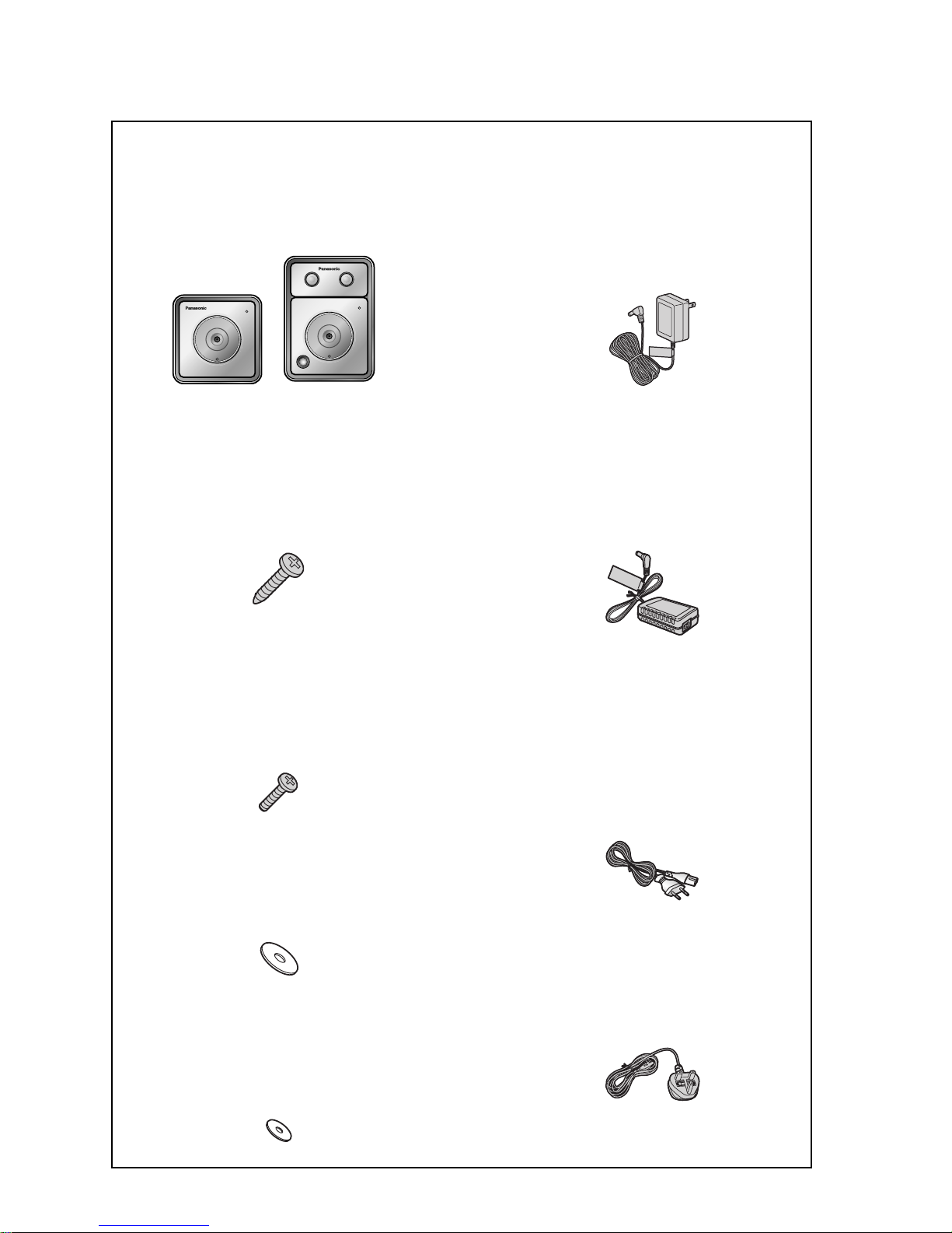
Preparation
Confirm the following items are included in the camera’s packaging.
Main Unit (1 pc.)
The appearance of your camera
depends on which model you have
purchased.
Screw A (6 pcs.)
Order No. XTB4 + 20AFJ
Used for wall mounting the camera.
Screw B (3 pcs.)
Order No. XTB26 + 10GVW
Used for securing the safety wire to the
camera and for fixing the right-angle
joint to the camera.
Washer L (1 pc. for the screw A)
Order No. XWG4F16VW
Used when securing the safety wire to
the wall.
Washer S (1 pc. for the screw B)
Order No. XWG26D12VW
Used when securing the safety wire to
the camera.
AC Adaptor (1 pc.)
Order No. PQLV206Y
Cord Length: About 3 m (9 feet 10
inches)
BL-C140A/BL-C160A
Order No. PQLV216CE1Z
Cord Length: About 3 m (9 feet 10
inches)
BL-C140CE/BL-C140E/BL-C160CE/
BL-C160E
AC cord (1pc. for BL-C140CE/
BL-C140E/BL-C160CE/BLC160E)
Order No. PFJA02A006Z
Cord Length: About 1.8 m (5 feet
11 inches)
BL-C140CE/BL-C160CE
Order No. PSJA1106Z
Cord Length: About 1.8 m (5 feet
11 inches)
BL-C140E/BL-C160E
BL-C140 BL-C160
6
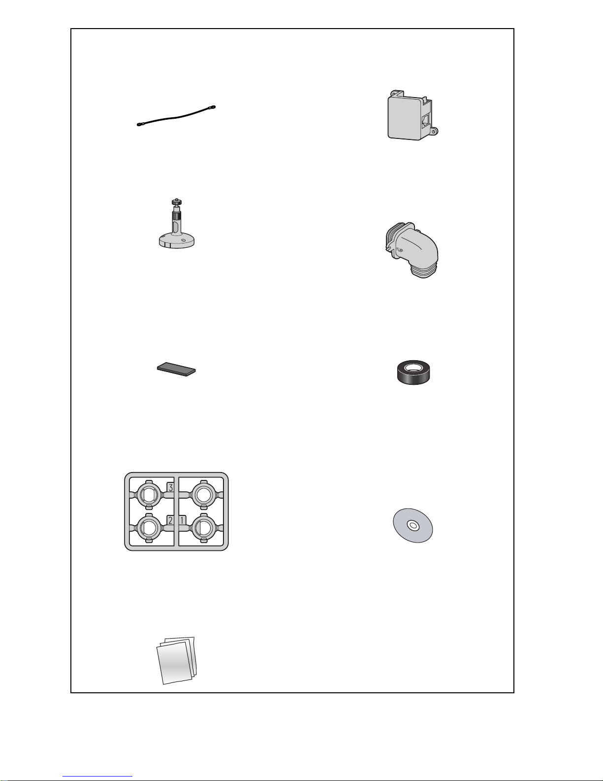
You will need the following additional items to install and configure the camera.
– a PC (see the system requirements in the Important Information document)
– 2 LAN cables (1 indoor cable and 1 outdoor cable)
– a router
Safety Wire (1 pc.)
Order No. PQME10080Z
Used to secure the camera when wall
mounting it.
Power Transfer Unit (1 pc.)
Order No. PNWP3C160A
Used to power the camera
Flexible Stand (1 pc.)
Order No. PQKL10082Z1
Used to attach the camera to the wall
Right-Angle Joint (1 pc.)
(with O-ring)
Order No. PNYCC160A
Used to protect the camera from
water
Foam Strip (1pc.)
Order No. PQHG10748Z
Used to protect the camera from water
Self Bonding Tape (1pc.)
Order No. PSHG1235Z
Used to protect the camera from
water
Sensor Range Cap (1 pc.)
[BL-C160 Only]
Order No. PQHG10765Z
Used to limit the sensor detection range
Setup CD-ROM (1 pc.)
Order No. PQQX15704TCD
Contains the Setup Program needed
to configure the camera, as well as
the camera’s documentation.*
*See the included Important Information for a
description of each document.
Important Information (1 pc.)
Installation Guide (this
document) (1 pc.)
Setup Guide (1 pc.)
7
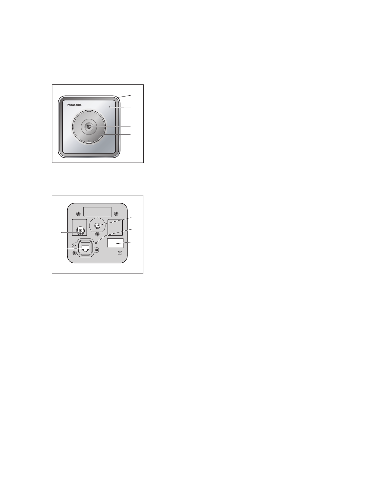
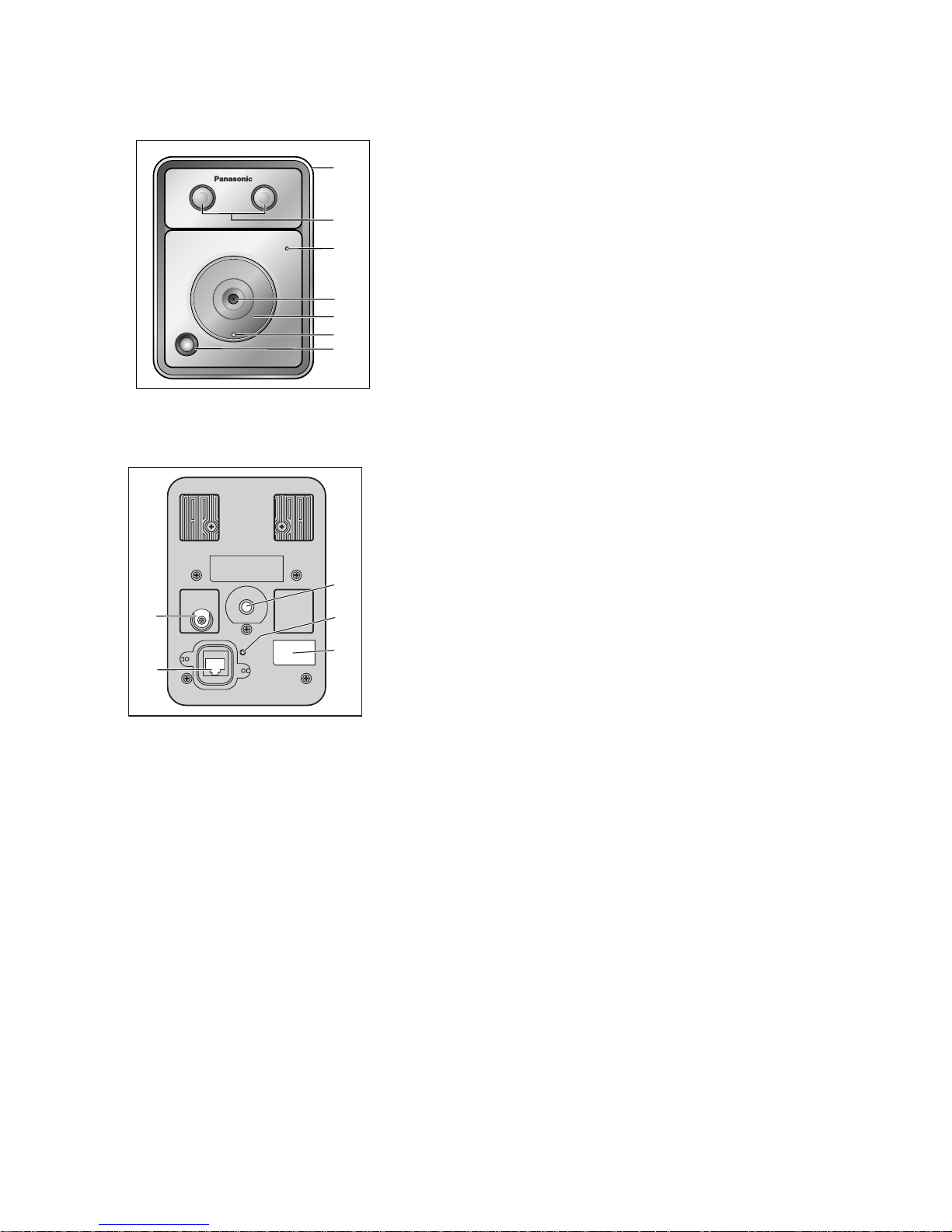
Camera Diagrams
BL-C140
*1 See 1.1 Understanding the Camera Indicator in the Troubleshooting Guide on the CD-ROM for indicator meaning.
Front View
A
B
C
D
Housing
Indicator
*1
Lens
Lens cover
Rear View
E
F
G
H
I
Safety wire hole
DATA/POWER IN
Stand mounting hole
FACTORY DEFAULT RESET button
Serial number and MAC address label
B
A
D
C
E
G
H
I
F
8
BL-C160
*1 See 1.1 Understanding the Camera Indicator in the Troubleshooting Guide on the CD-ROM for indicator meaning.
*2 The brightness sensor determines when the light turns on.
Front View
A
B
C
D
E
F
G
Housing
Light
Indicator
*1
Lens
Lens cover
Brightness sensor
*2
Built-in sensor (pyroelectric infrared
sensor)
Rear View
H
I
J
K
L
Safety wire hole
DATA/POWER IN
Stand mounting hole
FACTORY DEFAULT RESET button
Serial number and MAC address label
B
A
D
C
E
F
G
L
H
I
J
K
9
Choosing an Installation Location
Please read the following information about the camera’s motion detection feature and built-in
sensor (BL-C160 only) before deciding where to mount the camera.
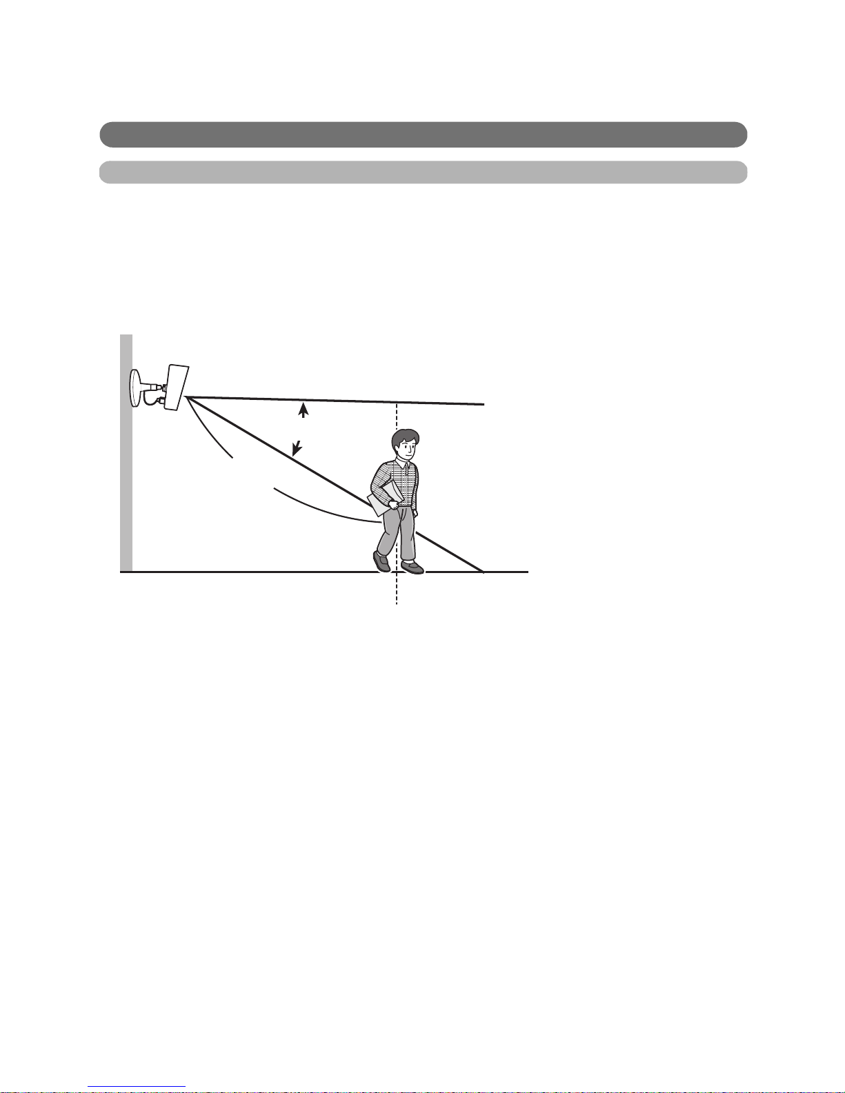
Detection Features
Motion Detection Feature
The camera detects changes in the images being displayed.
Active Motion Detection Range
• When the color of moving objects and the background are similar, motion may not be correctly
detected.
• If there are sudden changes to overall light levels, motion may be incorrectly detected.
• For up to 2 seconds immediately following the light turning on or off no detection will take place.
(BL-C160 only)
Camera
About 5 m (16 feet 5 inches)
Detection range length
About 45q
Detection range angle

10
Detection Range Characteristics of the Motion Detection Feature
• Motion detection becomes more difficult as it becomes darker.
• The motion detection function works by detecting changes in contour and brightness in moving
objects. This is done in order to reduce inaccurate detections due to changes in brightness.
• The camera can easily detect motion when objects move sideways in front of the camera, but
cannot easily detect motion when objects move toward the front of the camera.
Easy to detect
Difficult to detect
About 58q
Camera
Detection range
 Loading...