

Panasonic ANUP5031AS Installation Manual
A
Lamp Spot Type UV Curing Systems
NUP50
Users’ Manual
ARCT1F518E
2010.12|panasonic-denko.co.jp/sunx
Introduction
Thank you for your purchase of the Lamp Spot Type UV Curing Systems. In order to use the system
correctly, please read this manual carefully before use.
Safety Precautions Please use the following precautions to prevent injuries and accidents
In order to use the system correctly, read this manual carefully before installation, operation, or
inspection. Make sure you have good knowledge of the device, safety information, and these
precautions before use.
This manual classifies safety precautions into two categories: Danger and Warning.
Danger
Warning
Incorrect handling could result in death or serious injury.
Incorrect handling could result in serious injury or property damage.
Danger
● Do not subject the eyes or skin to direct or strongly reflected light when the lamp is on. When
operating, use UV-blocking protective goggles.
The ultraviolet light generated by the system includes ultraviolet light with extremely short
wavelength, which could induce inflammation (sunburn) if the skin is exposed to it directly, or its
reflection. In the case of the eyes, exposure over time (several hours) will cause burning and
watering, and the person exposed will not be able to maintain them open.
Warning
● Before repairs or calibration, turn off the power, and unplug the power cord.
● The system is charged with high voltage. Do not operate the device with charged parts exposed, or
repair or calibrate the device with the power turned on. Doing so could cause electric shock.
● Always earth the system. Failure to do so could cause electric shock.
● Make sure the lamp is completely cooled (about 30 min. or more after the lamp is turned off), then
remove the cover before replacing the lamp.
While the lamp is on, and immediately after it is turned off, it is very hot and under high pressure. In
this state, it could cause burning. If the lamp breaks, flying shards of glass could cause injury.
● Do not dismantle or modify the system. Doing so could cause fires or electric shock.
● Only press the "LAMP ON/OFF" button when the lead wire is firmly attached to the positive side of
the lamp. Pressing the "LAMP ON/OFF" button when the lead wire is touching the frame could
cause electric shock.
● If installing or removing the light guide fiber unit while the lamp is on, be sure to close the irradiation
shutter first.
Exposure to direct or strongly reflected light from the lamp could cause inflammation (sunburn) in
the skin or pain in the eyes.
● When unplugging the power cord, be sure to grasp both sides of the plug firmly, and pull out by the
plug. Pulling on the cord could break the cord, causing electric shock or a short-induced fire.
● Do not use the system if the power cord or plug is damaged, or the outlet connection is loose. Doing
so could cause electric shock or a short-induced fire.
● Keep the power cord unplugged when the system is not in use. Failure to do so could cause
deterioration of the insulation, leading to electric shock or electric leakage and fire.
2

Precautions before use
1) Do not connect the system to a power supply outside the rated voltage/frequency range listed on
the system or in this manual. Using with other than the indicated power could cause burnout.
• Input Power: Commercial 90 to 264 V AC, 50 Hz/60 Hz
2) Please use the system within the ambient conditions listed below. Using under other than the
indicated conditions could shorten the system lifetime.
• Ambient temp.: 10 to 40
• Relative humidity: No greater than 80% RH (at 25oC), with no condensation
3) When handling the lamp, do not touch the glass with your bare hands.
If foreign matter adheres to the glass, it could shorten the lamp lifetime or impact curing
performance, or cause the lamp to break. If the lamp is touched with a bare hand or becomes
soiled, wipe clean with alcohol.
4) Make sure the system's rubber legs are set horizontally parallel before use.
Using the system while it is titled, tipped on one side, or upside down could cause the lamp or
main unit to overheat and break. Doing so is also dangerous.
5) The system can be used in two modes: vertical light, and horizontal light. The magnets must be
set in accordance with the installation orientation. Failure to do this could cause the lamp to
shatter, or shorten its lifetime.
6) In order to avoid damage due to overheating, do not use if the area around the system is blocked,
or with two systems back to back. Blocking the bottom or back of the unit could change its internal
cooling conditions, causing damage due to overheating. If two systems are used back to back,
exhaust could cause damage due to overheating.
7) Do not leave the lamp on for prolonged periods while the cover is off. Doing so could cause the
lamp or system to overheat and break.
8) In order to avoid lighting failures due to overcooling, attach the light guide fiber unit to the jack on
the front of the main unit, and make sure it is inserted before use.
9) Do not use the lamp for more than 3,000 hours. Doing so could cause it to break.
Even if the lamp has been used for less time than this, you should always keep a spare lamp on hand.
10) As a rule of thumb, the lamp should be turned on no more than twice per day. Turning the lamp
on more than twice per day could shorten its lifetime.
11) Perform periodic system cleaning about once a month. Dust or other foreign matter could cause
fires or impact lamp cooling.
12) Opening and closing the shutter in rapid succession, vie panel operation or direct operation,
could cause malfunction (minimum shutter open 1 second, minimum shutter closed 1 second)
Warranty and compensation for production
Warranty
Any failures that occur within 1 year (8 hours of use per day) of delivery, under
conditions of normal use, will be repaired free of charge. This does not apply,
however, if the failure was the fault of the user, or due to normal wear or force
majeure, including natural disasters.
Note: If the system is used for 12 or more hours per day, the warranty period is 6 months.
Compensation for Production
We cannot compensate losses due to halted production or defects caused by
system issues.
o
C
3

Contents
1. Features of the ANUP50 Aicure............................ 5
2. Product Components ............................................ 6
3. Name and Function of Each Part.......................... 7
Front/Back ....................................................... 7
Operation Panel .............................................. 8
4. Assembly............................................................. 10
4.1. Installing the Magnet........................................ 10
4.2. Installing the Lamp........................................... 12
4.3. Installing the Light Guide Fiber Unit................. 14
About the light guide fiber unit....................... 14
Installing the light guide fiber unit .................. 14
Installing the lens unit (optional).................... 15
Installing the UV-blocking filter
(optional) ....................................................... 15
5. Installation........................................................... 16
5.1. Installation Orientation ..................................... 16
5.2. Installation Conditions...................................... 16
5.3. General Guide for Irradiation Distance
and UV Intensity .............................................. 17
6. Starting and Stopping Operation......................... 18
6.1. Starting Operation (turn on lamp) .................... 18
6.2. Stopping Operation (turn off lamp)................... 19
7. Irradiation Modes ................................................ 20
Manual Irradiation.......................................... 20
Timer Irradiation ............................................ 20
Pattern Irradiation.......................................... 20
UV Intensity Setting....................................... 20
UV Autocontrol Feature ................................. 21
Eco Mode Feature......................................... 22
Setting Lock Feature ..................................... 23
8. Irradiation.............................................................24
8.1. Manual Irradiation.............................................24
8.2. Timer Irradiation................................................27
8.3. Pattern Irradiation .............................................29
9. Operation via External Signals ............................34
9.1. How the External Control Connector
and Signals Work .............................................34
9.2. Operating via External Signals .........................37
Manual Irradiation ..........................................37
Timer Irradiation.............................................37
Pattern Irradiation ..........................................38
10. UV Measurement and Calibration Mode ...........39
10.1. Measuring UV Intensity ..................................39
10.2. Calibrating UV Intensity ..................................41
Calibration during UV Intensity Measurement
10.3.
UV Intensity Calibration via External Signals
10.4.
11. Replace Lamp Indicator Function......................44
Setting the Lamp Replacement Time.............44
12. Replacing the Lamp...........................................45
12.1. Replace the Lamp ..........................................45
12.2. Replacing the Positive Lamp Lead Wire ........47
13. Safety Measures................................................49
13.1. Safety Circuit ..................................................49
14. Troubleshooting.................................................50
14.1. Possible Issues...............................................50
14.2. If an Error Occurs ...........................................51
15. Specifications.....................................................54
16. Dimension Drawing ...........................................55
17. List of Optional and Supplementary Parts .........56
18. Manual Revision History....................................57
.......42
........43
4

ANUP50 Aicure
Features of the ANUP50 Aicure
1. Features of the ANUP50 Aicure
The ANUP50 Aicure is an ultraviolet curing system that quickly hardens UV resins (inks, adhesives,
and coatings) via irradiation with ultraviolet light. Focused irradiation of UV resins coated on minute
surfaces (3 to 15 mm diam.) such as the lenses of CD, MD, and DVD players, and the LCD panels of
notebook PCs and the like, with UV radiation enables precise adhesion.
Automatically compensate for deterioration of UV intensity via the UV auto control
feature
This feature compensates for decrease of UV intensity due to passage of lamp use time. This
maintains stable UV intensity until the end of the lamp lifetime.
Pattern irradiation matching to the resin/material to cure (programmable UV
irradiation)
Switching irradiation patterns with programmed UV intensities and irradiation time in keeping with the
qualities of the material to cure will prevent curing shrinkage, and warping in optical products and the
like.
Eco (energy saving) mode
A maximum of 15% electric power consumption can be reduced when UV irradiation is not performed.
Digital display with no individual differences
Every configuration can be displayed using easy-to-operate switches. UV radiation can be set in
minute gradations, between 0 and 100%.
Long-life, one-touch replacement lamp
This 200 W lamp does not require calibration of the light axis and can be installed with a single
operation.
Free power source
Supports world-wide power: 100 to 240 V AC.
Support for vertical and horizontal use
Supports vertical mode (vertical lamp type) with its smaller footprint, and the stackable horizontal
mode.
UV intensity control
In-process UV intensity check and calibration can be performed by using the optional small-size UV
sensor.
5
ANUP50 Aicure
A
A
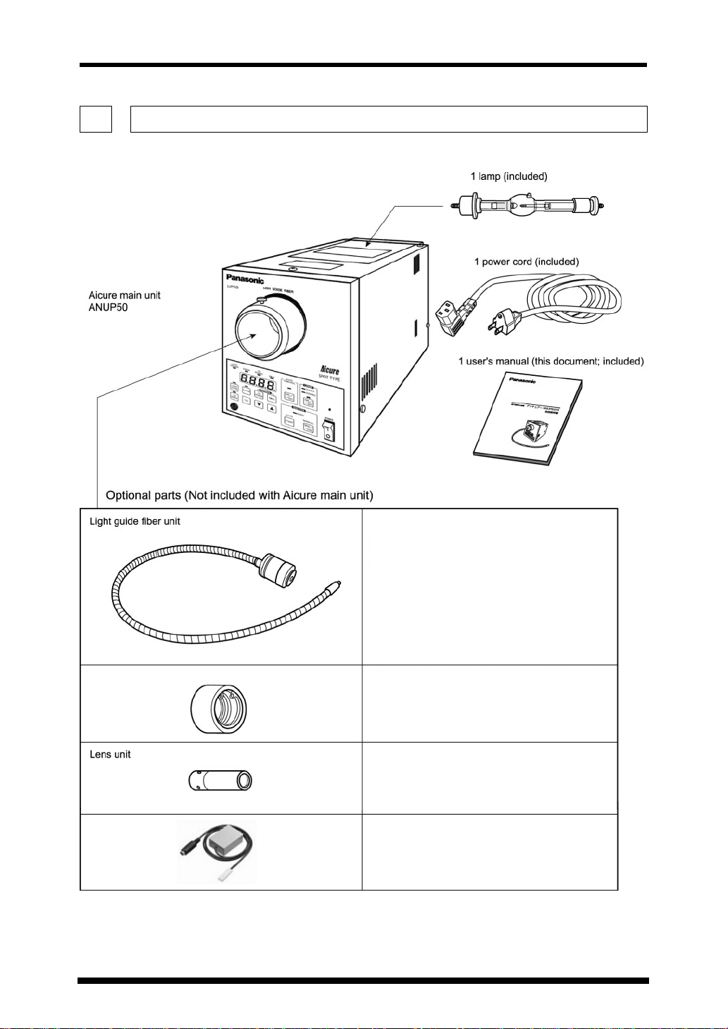
Product Components
2. Product Components
Please check the contents of your package.
Heat-ray cut filter unit
UV sensor
lways attach the light guide fiber unit when
using the Aicure. Different models are
available for each type of branch and beam
diameter; use the one that suits your purpose
ttach to the light guide fiber unit (input side)
to reduce the temperature of the irradiation
area
When irradiating a small area of about 3 to 4
mm diameter, attach this to the light guide fiber
unit (output side)
Use for UV intensity measuring or calibration.
6
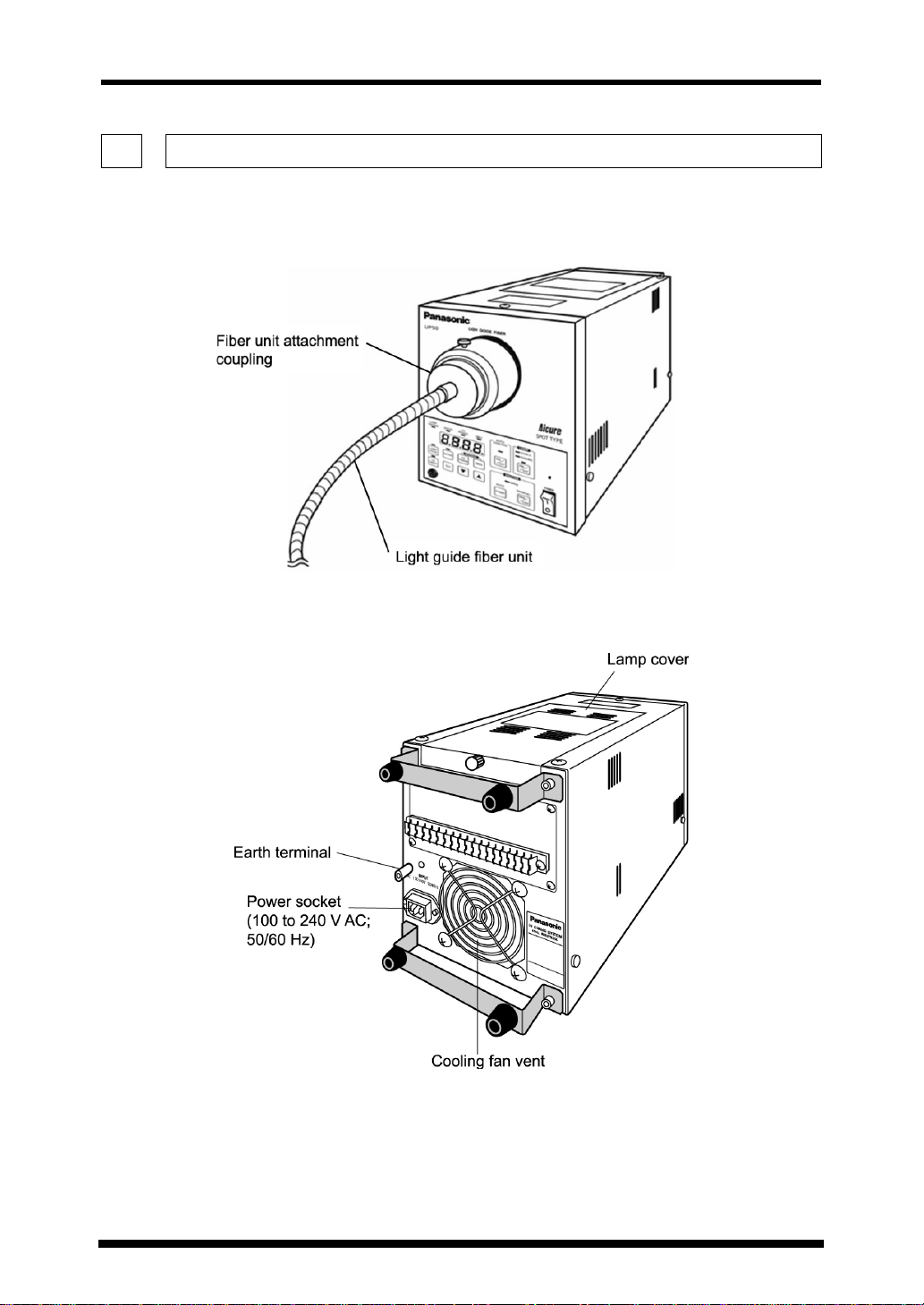
Front
Name and Function of Each Part
3. Name and Function of Each Part
ANUP50 Aicure
Back
7
ANUP50 Aicure
Name and Function of Each Part
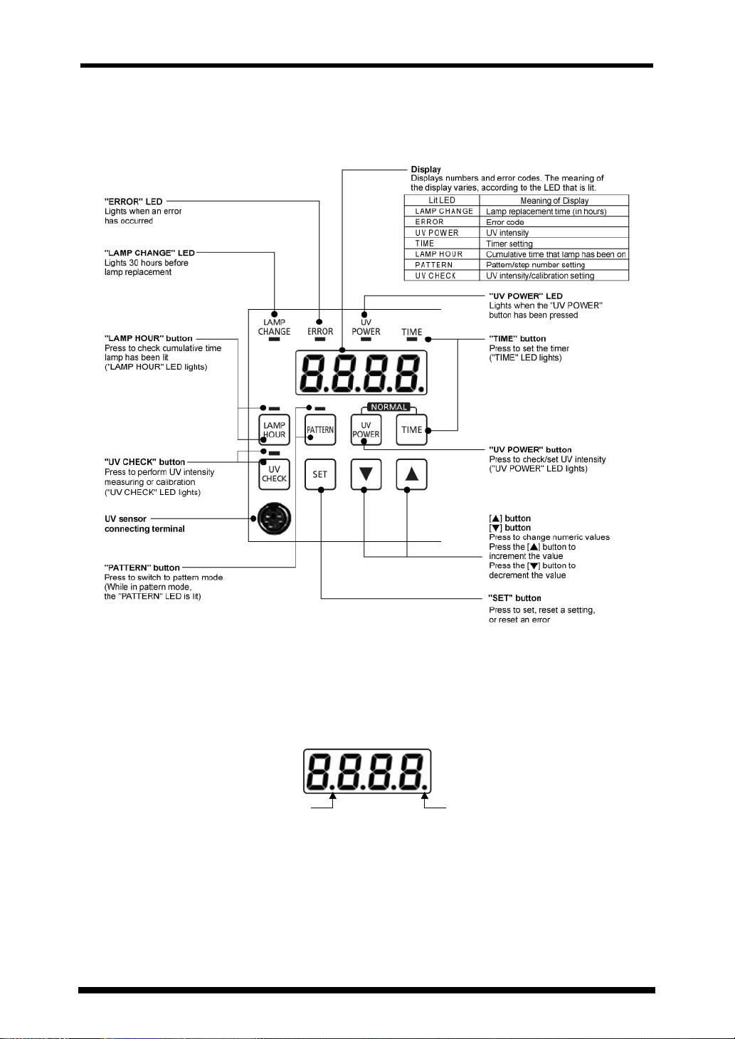
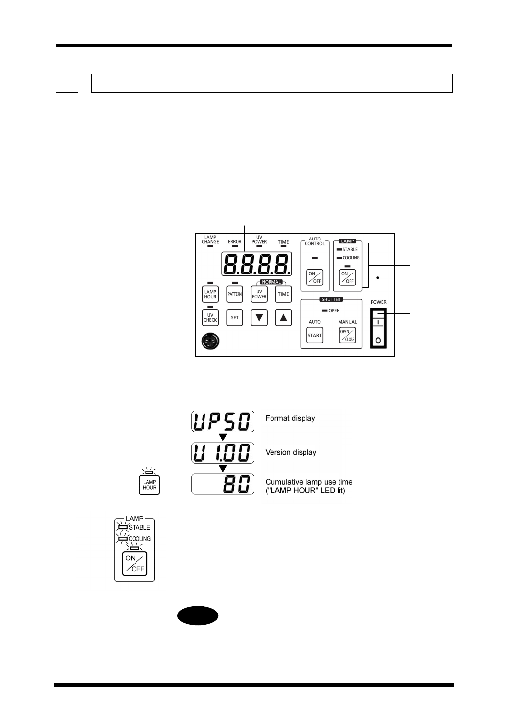
Operation Panel
Display’s LED
時点滅
時点滅
8
Flashes when the lamp is on Flashes when the setting lock is active
ランプ点灯時点滅設定ロック
ランプ点灯時点滅設定ロック
ANUP50 Aicure
Name and Function of Each Part
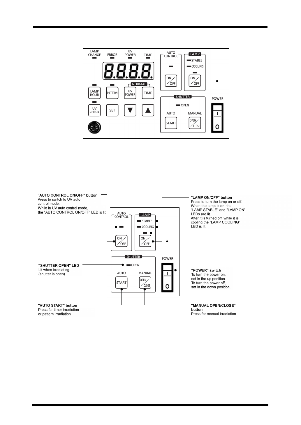
Operation Panel (on the Whole)
「AUTO CONTROL ON/OFF」スイッチ
「AUTO CONTROL ON/OFF」スイッチ
UVオートコントロールモードへの切換え時に押す
UVオートコントロールモードへの切換え時に押す
UVオートコントロール実行中は、
UVオートコントロール実行中は、
「AUTO CONTROL ON/OFF」LED点灯
「AUTO CONTROL ON/OFF」LED点灯
「SHUTTER OPEN」LED
「SHUTTER OPEN」LED
照射中(シャッター開状態)、点灯
照射中(シャッター開状態)、点灯
「AUTO START」スイッチ
「AUTO START」スイッチ
タイマ照射時または、パターン照射時に押す
タイマ照射時または、パターン照射時に押す
「LAMP ON/OFF」スイッチ
「LAMP ON/OFF」スイッチ
ランプの点灯/消灯時に押す
ランプの点灯/消灯時に押す
ランプ点灯中は、「LAMP ON」LED点灯
ランプ点灯中は、「LAMP ON」LED点灯
ランプ点灯安定後は、「LAMP STABLE」LED点灯
ランプ点灯安定後は、「LAMP STABLE」LED点灯
ランプ消灯後、冷却中は、「LAMP COOLING」LED点灯
ランプ消灯後、冷却中は、「LAMP COOLING」LED点灯
「POWER」スイッチ
「POWER」スイッチ
電源投入時は、上側を押す
電源投入時は、上側を押す
電源遮断時は、下側を押す
電源遮断時は、下側を押す
「MANUAL OPEN/CLOSE」スイッチ
「MANUAL OPEN/CLOSE」スイッチ
マニュアル照射時に押す
マニュアル照射時に押す
9
ANUP50 Aicure
Assembly
4. Assembly
Warning
Before assembly, turn off the power, and unplug the power cord.
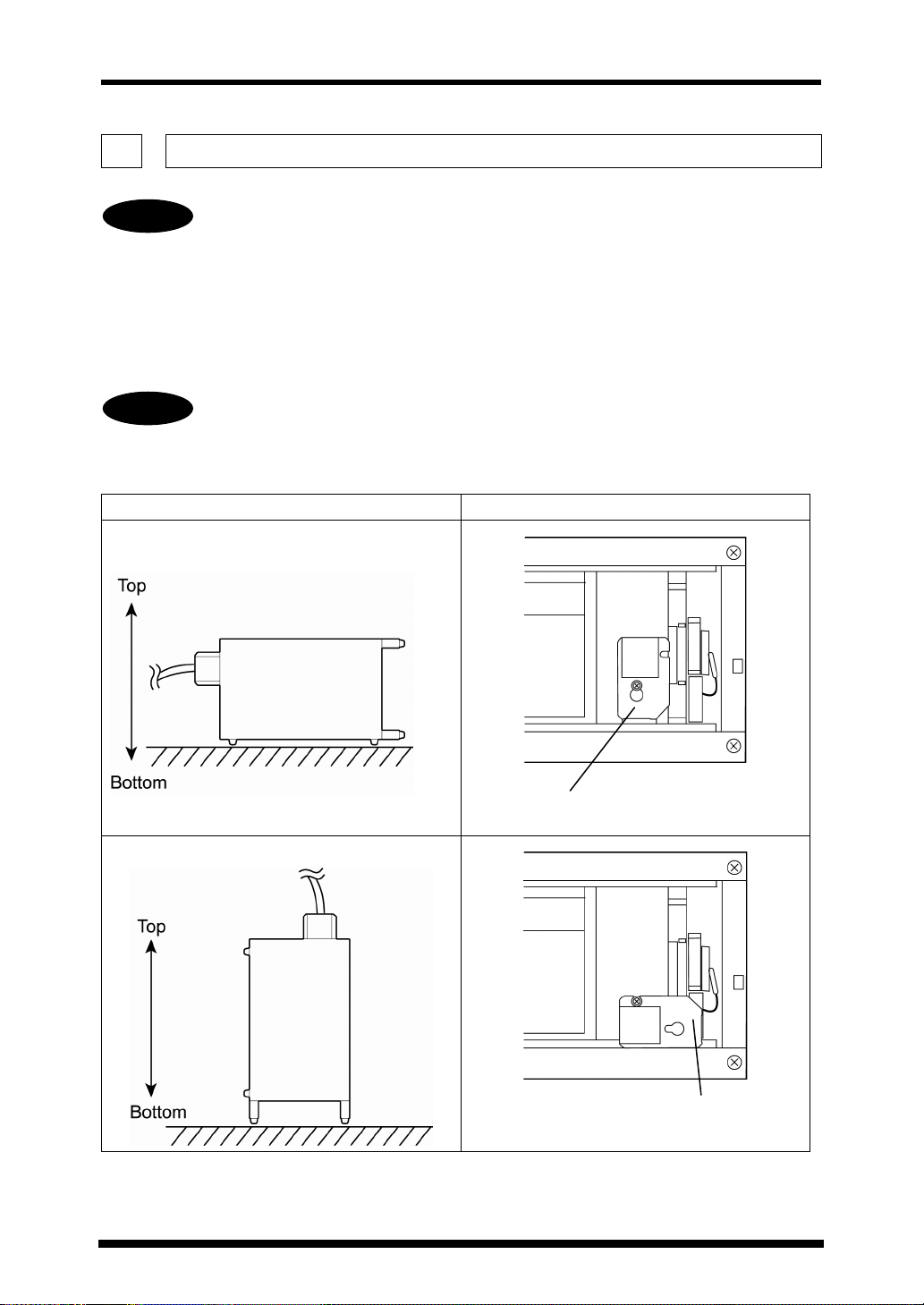
4.1. Installing the Magnet
The ANUP50 Aicure can be used in two orientations: horizontal illumination and vertical
illumination. The orientation of the installed magnet must be changed in accordance with
the orientation of the main unit, in order to ensure the stability of the lamp.
Warning
Installation Orientation Magnet Mount Position
Be sure to set the magnet in accordance with the installation orientation. Failure to
do so could cause the lamp to shatter, or shorten its lifetime.
Installation Orientation Mount Direction
Horizontal Illumination
10
Magnet
(Factory Setting)
Vertical Illumination
Magnet
Install the Magnet
ANUP50 Aicure
Assembly
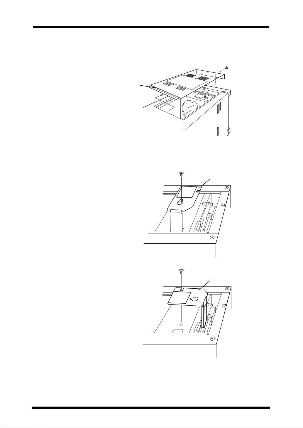
1
Loosen 1 bolt, and remove the lamp cover on top of the
main unit.
Lamp cover
2
Loosen 1 bolt, and remove the magnet plate.
3
Change the orientation of the magnet plate in accordance
with the installation orientation, then lock in place again.
Magnet plate
Orientation for horizontal illumination (factory setting)
Magnet plate
Orientation for vertical illumination
4
Mount the lamp cover back in place.
11
ANUP50 Aicure
Assembly
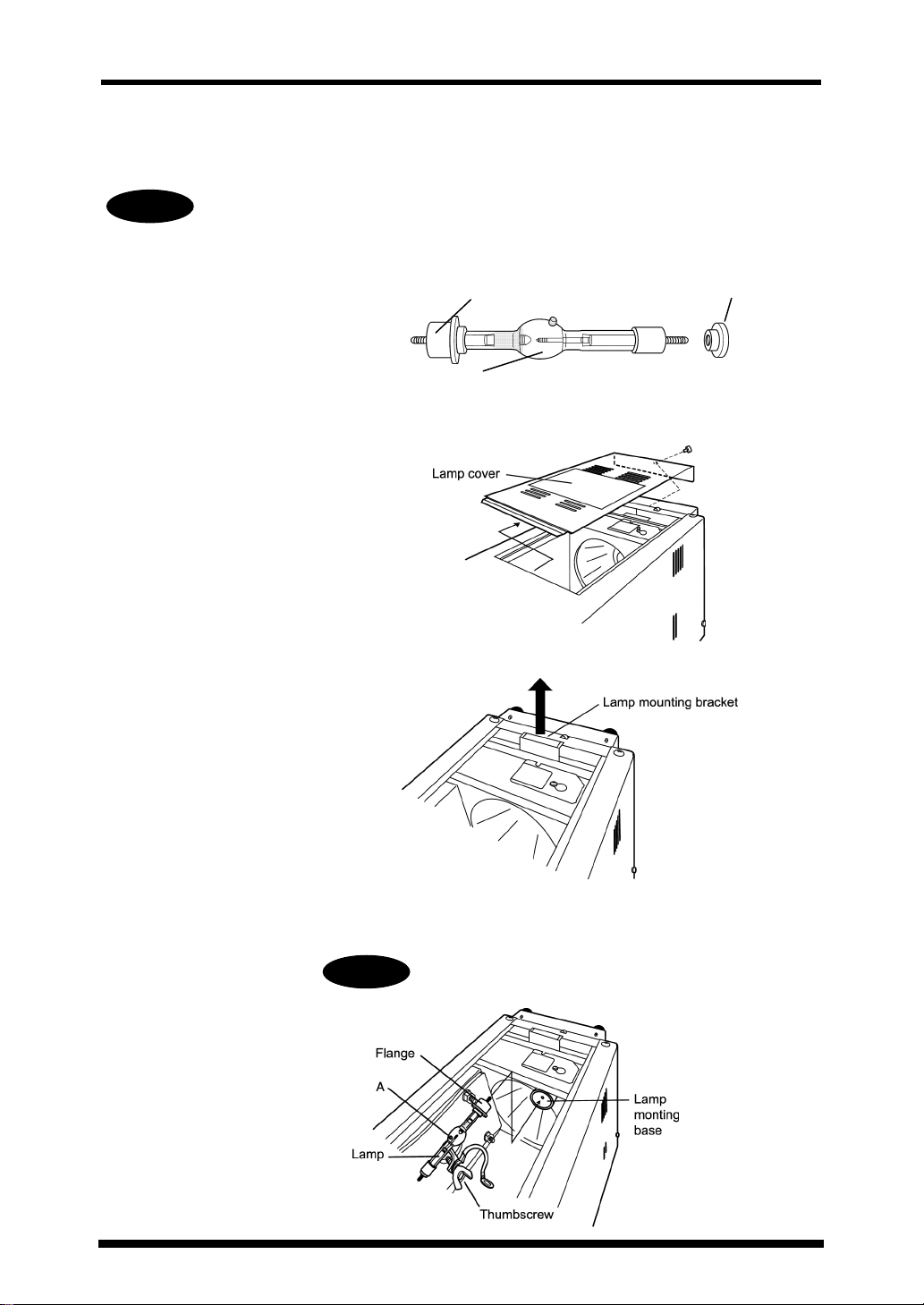
4.2. Installing the Lamp
Warning
Do not touch the lamp with your bare hands. Use clean gloves or gauze when
installing the lamp.
1
Remove the lamp's knurl nut.
2
Loosen 1 bolt, and remove the lamp cover on top of the
main unit.
3
Lift up the lamp mounting bracket.
Flange
A
Lamp
Knurl nut
12
4
Press the lamp flange into the hole in the lamp mounting
base.
Warning
Put the A part of the lamp up.
ANUP50 Aicure
Assembly
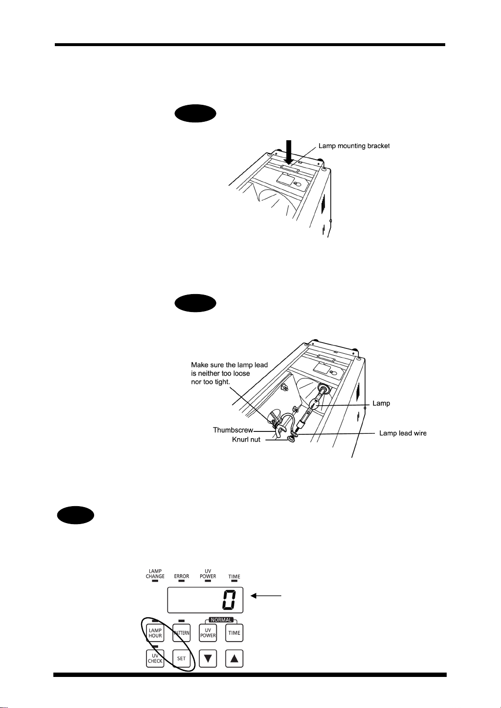
5
With the lamp pressed in, push the lamp mounting
bracket down.
Warning
If the lamp is not completely locked in place,
illumination output will decrease.
Warning
6
Pass the lamp lead wire through the lamp screw hole,
then fasten the knurl nut (removed in step 1) securely
back in place.
Warning
Make sure there is no gap between the Thumbscrew,
knurl nut and lamp lead wire terminal.
7
Fasten the lamp cover back in place.
When you install a new lamp, you must reset the cumulative lamp use time. After
installing the lamp, when you first turn the power on, perform the following steps:
1. Press the "LAMP HOUR" button.
2. Press the "LAMP HOUR" and "SET" buttons simultaneously until you hear a beep
sound (at least 1 second).
Make sure that the display reads "0".
13
ANUP50 Aicure
Assembly
4.3. Installing the Light Guide Fiber Unit
About the light guide fiber unit
The light guide fiber unit comes in a number of bundle diameters (3.5 mm, 5 mm, and 8 mm), number
of branches (1 to 4), and other varieties. Select the type that meets your needs. To increase the UV
intensity, attach a lens unit (optional) to the irradiation outlet of the light guide fiber unit. To reduce the
temperature of the irradiation unit, attach a heat-ray cut filter (optional) to the irradiation inlet of the
light guide fiber unit.
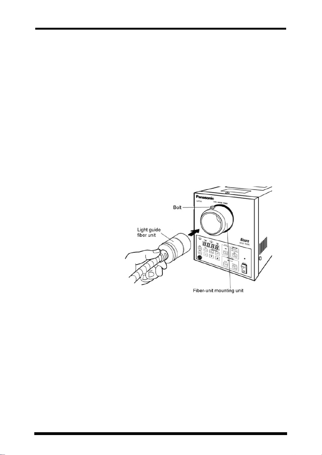
Installing the light guide fiber unit
1
Loosen the bolt on the fiber-unit mounting inlet on the
front of the main unit.
2
Press the light guide fiber unit into the fiber-unit mounting
inlet all the way, then tighten the bolt and lock it in place.
14
ANUP50 Aicure
Assembly
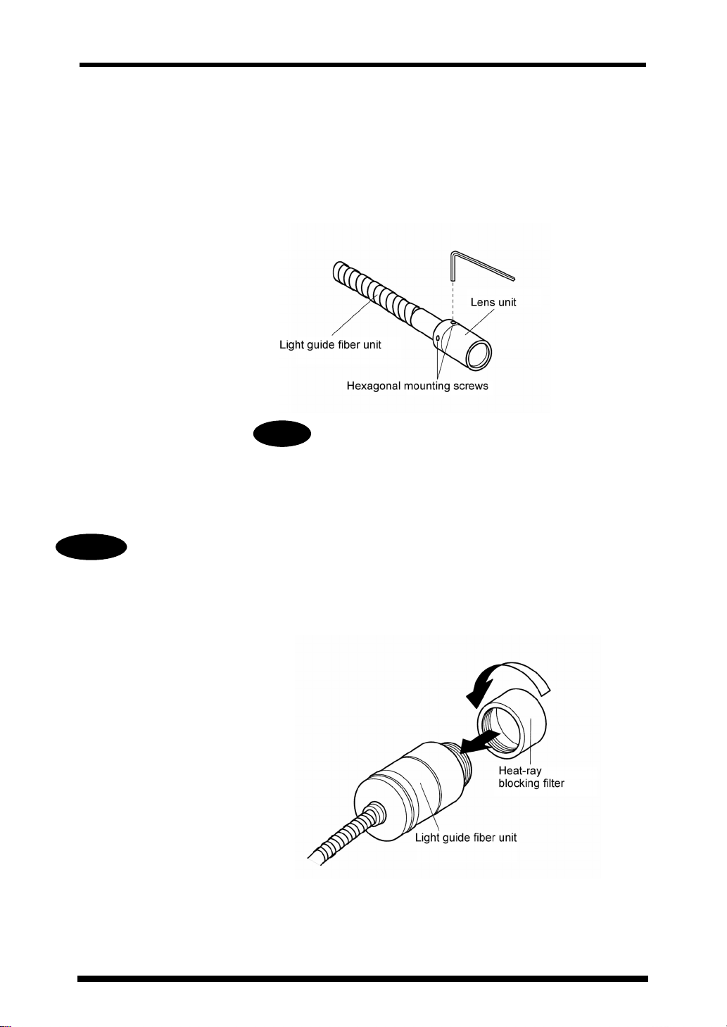
Installing the lens unit (optional)
Use a lens unit to increase the UV intensity by focusing the UV light.
1
Press the lens unit all the way into the light guide fiber
unit irradiation outlet.
2
Using a hexagonal wrench (1.5 mm), tighten the two
hexagonal mounting screws.
Warning
Installing the UV-blocking filter (optional)
Use a heat-ray cut filter unit to reduce the temperature of the irradiated application. This unit passes
through short-wavelength radiation (254 to 436 nm), and blocks heat rays greater than this.
Warning
Mount the heat-ray cut filter before attaching the light guide fiber unit to the Aicure main
unit.
1
Screw the heat-ray cut filter all the way onto the light
guide fiber unit irradiation inlet.
Do not scratch the lens or touch it with your bare hands.
If the lens becomes dirty, wipe it clean with alcohol.
2
Press the light guide fiber unit all the way all the way into
the fiber-unit mounting inlet on the main unit, then lock it
in place with the bolt.
15
ANUP50 Aicure
Installation
5. Installation
Install the ANUP50 Aicure under the conditions above.
5.1. Installation Orientation
The ANUP50 Aicure can be oriented in two ways: a space-saving vertical illumination (upright)
orientation, and a horizontal illumination (sideways) orientation that allows stacking. You must change
the mounting orientation of the magnet inside the main unit, in accordance with the installation
orientation. See 4-1. Installing the Magnet for details.
Warning
Be sure to set the magnet in accordance with the installation orientation. Mounting the
magnet in a different position could cause the lamp to shatter, or shorten its lifetime.
5.2. Installation Conditions
1) Ambient temp.: 10 to 40oC (50 to 104oF)
2) Relative humidity: No greater than 80% (at 25
condensation
3) Make sure the rubber legs are set horizontally parallel.
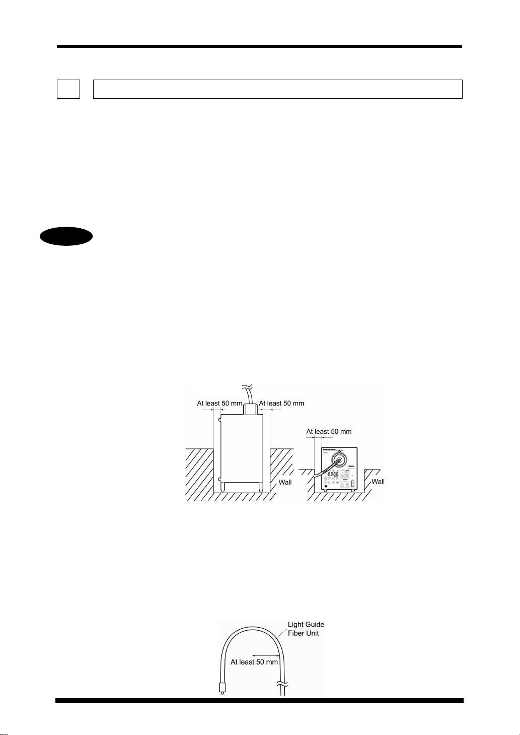
4) In order to avoid damage due to overheating, do not use if the area
around the system is blocked, or with two systems back to back.
Vertical
5) The dimensions of the main unit are 165 x 200 x 325 mm
(LxHxD), but you should take the state of the unit with a light
guide fiber unit attached into account.
6) The minimum allowable bending radius for the light guide fiber unit is
50 mm. (When bundle diameter is 3.5 mm and 5 mm.) Using the unit
with a curve radius of less than 50 mm could damage it. Additionally,
you should not touch the end of the light guide directly with your bare
hands. If it becomes dirty, the level of UV light will be decreased.
o
C/77oF), with no
16
Note:
The minimum allowable bending
radius is 80 mm with a bundle
diameter of 8 mm.
ANUP50 Aicure
Installation
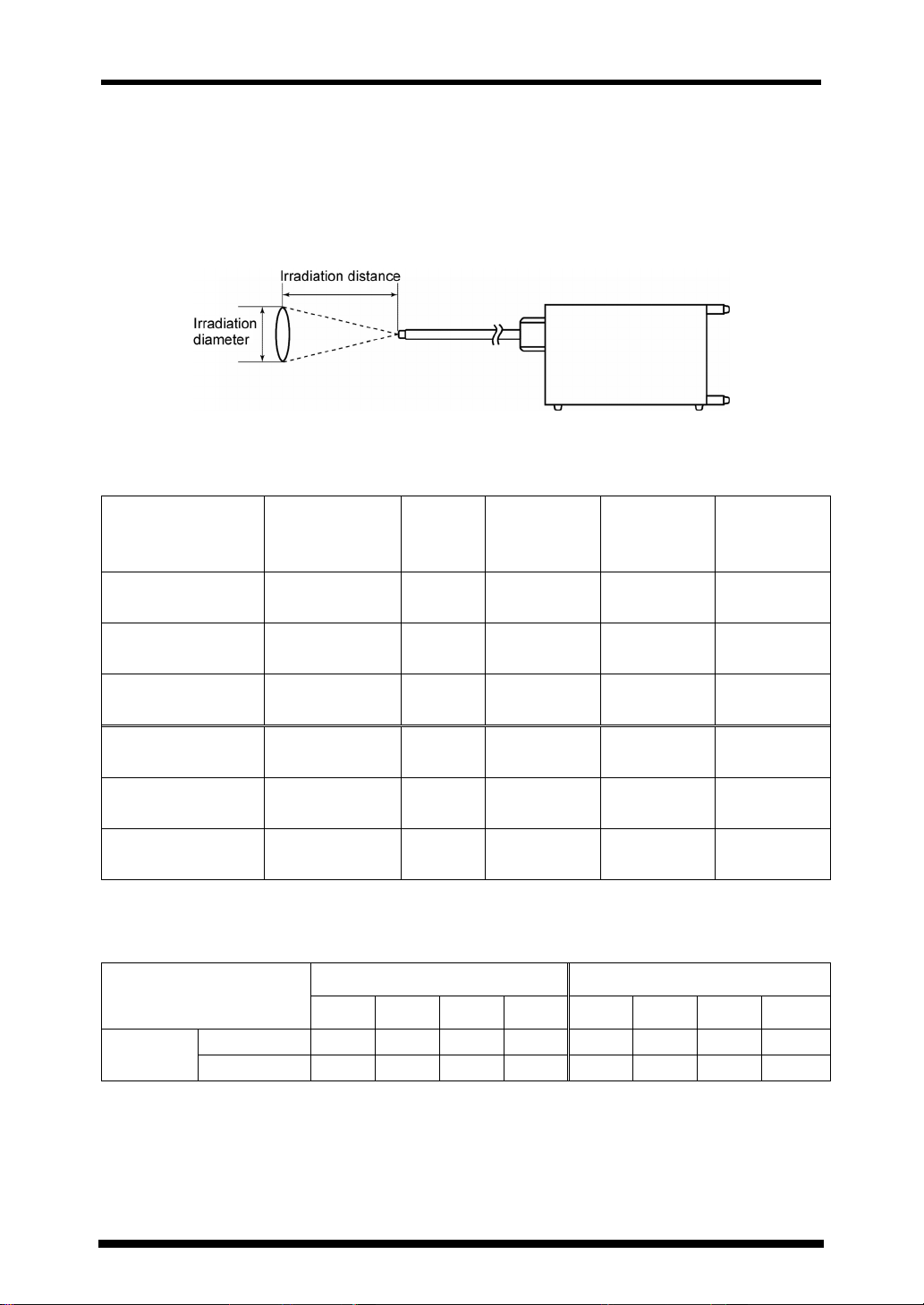
5.3. General Guide for Irradiation Distance and UV Intensity
Set the irradiation distance in accordance with the size of the area to be irradiated (irradiation
diameter) and the required UV intensity. Below is shown the relationship between irradiation distance
and irradiation diameter, as a general guide for setting the irradiation distance and UV intensity.
Relationship between irradiation diameter and irradiation distance of each fiber unit, with UV
intensity of 70% (reference values)
Measured with 1mm diam. sensor
Fiber unit model
number
ANUP5051
(No lens)
ANUP5051AS
(w/AS lens)
ANUP5051BS
(w/BS lens)
ANUP5031
(No lens)
ANUP5031AS
(w/AS lens)
ANUP5031BS
(w/BS lens)
General guide for ratio of UV intensity to number of fiber-unit branches
Fiber unit
Irradiation outlet
bundle diameter
5 mm 1 15 2,300 3.5 mm
5 mm 1 15 3,560 4.0 mm
5 mm 1 30 1,840 6.0 mm
3.5 mm 1 15 1,220 5.0 mm
3.5 mm 1 15 3,900 2.5 mm
3.5 mm 1 30 2,020 3.5 mm
Measured with 1mm diam. sensor, at 15 mm irradiation distance
No.
branches
5 mm diam. 3.5 mm diam.
Irradiation
distance
(mm)
UV intensity
(mW/cm
2
)
Irradiation
diameter
UV
intensity
No lens
With lens
1B 2B 3B 4B 1B 2B 3B 4B
100% 75% 55% 50% 100% 80% 62% 57%
100% 65% 53% 45% 100% 75% 60% 50%
17
ANUP50 Aicure
Starting and Stopping Operation
6. Starting and Stopping Operation
Start operation of the ANUP50 Aicure in the following order: (1) turn on the power; (2) turn on the
lamp; and (3) begin irradiation (open shutter). See Section 7. Irradiation Modes and 8. Irradiation for
details about irradiation modes and operation.
Here, we will explain how to turn the power and the lamp on and off (common to every irradiation
mode).
6.1. Starting Operation (turn on lamp)
2
2
3・4
3・4
1
1
1
Press upper half of the "POWER" switch.
2
Make sure that the display shows the cumulative lamp
usage time, and also make sure you hear a beep sound.
形式表示
形式表示
バージョン表示
バージョン表示
ランプ累積点灯時間
ランプ累積点灯時間
(「LAMP HOUR」LED点灯)
(「LAMP HOUR」LED点灯)
3
In the "LAMP" section, press the "ON/OFF" button until
you hear a beep sound. The lamp will turn on, and the
LED above the "ON/OFF" button will light.
4
Make sure that the "STABLE" (lamp stable display) and
"COOLING" (lamp cooling) LEDs in the "LAMP" section
are lit.
Warning
Wait about 30 seconds after the "STABLE" LED
lights before starting irradiation. Immediately after
the lamp is turned on, it is unstable and intensity is
still low. Beginning irradiation in this state could
lead to defective curing, and should be avoided.
18
 Loading...