

Panasonic ANR11151 Installation Manual
INSTRUCTION MANUAL
Photoelectric Displacement Sensor
Safety Precautions
Be sure to read this instruction manual before installation, operation, maintenance and inspection.
Before using the product, familiarize yourself with all product information, safety information and cautions.
In this instruction manual, the safety precaution level is classified into 'Warning' or 'Caution'.
WARNING
CAUTION
٨٨When this product is used in applications where serious injury or serious material damage might re-
sult, take safety countermeasures, such as a double-safety mechanism etc.
Do not use this product in a combustive-gas atmosphere. It may cause an explosion.
٨٨Do not use this product outside the specifications. Abnormal heat or smoking could result.
Never disassemble or modify the product. Electric shock or smoking could result.
Be sure to follow the precautions below to prevent any injury or accidents from occurring.
If the product is mishandled, death or serious injury could result.
If the product is mishandled, serious injury or material damage could result.
Cautionary items for laser beam handling
This product is designated as a component intended for incorporation into another product and is based
on the standards required by the U.S. Food and Drug Administration.
1.
This product utilizes a Class Τ laser (wavelength 685nm) as the light source of the laser.
2.
For safety reasons, avoid direct or indirect (e.g.) reflection from the glossy target) exposure of human eyes to
beam. For safety reasons, do not disassemble the unit. This product may not have an automatic laser-shutoff
function when the unit is disassembled.
3.
To avoid direct exposure to beam, it is recommended that the sensor be installed so that the beam height is
higher or lower than operator's eyes.
Furthermore, the sensor should be fixed so that its beam hits diffuse-reflective or dark targets.
Be sure not to expose your eyes to the beam or the reflected beam from the glossy targets.
CAUTION-Use of controls or adjustmens or performance of procedures other than those specified herein
may result in hazardous radiation exposure.
٨٨Labels
Caution and Aperture labels, Identification and Certification label below are pasted on the sides of the sensor.
ٟCaution and Aperture Label ٟIdentification and Certification Label
ANR11 series ANR12 series
CAUTION
LASER RADIATION
DO NOT STARE
SEMICONDUCTOR LASER 685nm
LASER APERTURE
AVOID EXPOSURE
LASERRADIATION IS
EMITTED FROM THIS
APERTURE
MAXIMUM OUTPUT0.4mW
PULSE DURATION15ǴU
CLASSΤLASER PRODUCT
Beam stopper
A beam stopper is attached to
this product. To prevent accidental human exposure to laser
radiation, set the beam stopper
over the laser emitting faces
when laser operation is not required.
CE MARKING
1
The Micro Laser Sensor LM10 conforms to the following standards under the EMC Directive and the Low voltage Directive.
٨EMC Directive (89/336/EEC)
EN 50081-2㧦1993
EN 50082-2㧦1995
PART DESCRIPTION
2
٨Sensor (ANR11 series)
Receiver
Emitter
٨Sensor, Relay cable (ANR12 series)
Connector to Controller
٨Controller
Single comparator type
MICRO LASER
SENSOR LM10
OPERATION
ԙ
LASER BRT/DRK
DISPLACE
MENT
ADJ
-
Ԝ
SPEED(Hz)
ԝ
CAUTION
LASER RADIATION
DO NOT STARE
Ԙ
Ԙ
LASER APERTURE
AVOID EXPOSURE
LASERRADIATION IS
EMITTED FROM THIS
APERTURE
Ԛ
Ԛ
ԟ
Ԡ
ԛ
ԡ
Ԣ
Ԟ
Connector
INTO BEAM
SEMICONDUCTOR LASER 685nm
MAXIMUM OUTPUT1.6mW
PULSE DURATION15ǴU
CLASSΤLASER PRODUCT
When beam stopper is used:
Set the beam stopper to either side of
the sensor with the accessory screws.
Connector to
Controller
Connector for sensor
and expansion cable
Window comparator type
LASER
LOW
SET
ԧ
SPEED(Hz)
INTO BEAM
SET
SET
+
GAIN
AUTO
LOW
Micro Laser Sensor
WARNING
CAUTION
SUNX Limited
2431-1, Ushiyama-cho, Kasugai, Aichi,486-0901 Japan
KDCL
Manufactured: April, 2005
Product complies with 21 CFR
Chapter 1, Subchapter J
in effect as of date of manufacture.
٨Low Voltage Directive (72/23/EEC)
EN 60825-1㧦1994
ٟ
For each type
ԘԙLaser emission indicator LED
The LED lights up during laser emission or just before its
emission. To indicate an alarm condition, the LED on the sensor head blinks.
Ԛ Measuring range indicator LED
Blinks when a target is within the measurable range. Lights
up when a target is around the measurement center. However, it may light up or blink even with a significant error in
the measuring range when the alarm is enabled.
ԛ Alarm LED
Lights up when measurement is not possible (not enough
light [DARK] or too much light [BRIGHT]).
Ԝ Zero-point adjusting potentiometer
Adjusts the zero-point position to within a r10% of F.S.
Use to make minute adjustment after installing the sensor.
ԝ SPEED selection switch
The response speed can be set to one of three settings to
allow adjustment for the target speed. When high response
speed is unnecessary, set to the 10Hz mode.
Ԟ GAIN selection switch
Under normal conditions, set to AUTO. During edge detection and other applications where you want to cut out the low
light level areas, set to LOW.
ԟ I/O cable
ٟOnly for single comparator type
Ԡ Operation indicator LED
Lights up when NEAR / DARK ON output is ON.
ԡ
Analog displacement output switch
Switches between the displacement data / intensity data
output and the comparative value setting output.
Ԣ Comparative value setting potentiometer
Sets the comparative value. By setting the analog displacement output switch to the right, the set value can be monitored by the analog displacement output.
ٟOnly for window comparator type
ԣ Operation indicator LED
The LED lights up that corresponds to the comparative
output currently being output.
Ԥ Display / Analog displacement output switch
Switches between the displacement data output and the
LOW
DISPLACEMENT
-
MICRO LASER
SENSOR LM10
ADJ
HIGH
BRT/DRK
HIGH
SET
V
HIGHLOW
+
GAIN
AUTO
LOW
comparative value setting output.
ԣ
ԥ LCD display
3-digit display of the displacement data or the upper and
Ԥ
lower limit value.
Ԧ HIGH limit setting potentiometer
ԥ
ԧ LOW limit setting potentiometer
Sets the comparative value's upper limit (HIGH) and lower
Ԧ
limit (LOW). Set it so that the HIGH value is greater than
the LOW value. By setting the display and analog
displacement output switch to either LOW or HIGH, you can
monitor the set value by display and analog displacement
output. When not set, return the switch to the center
position.
LM10
CME-LM10F No.2148-00
When beam stopper is not used:
Set the beam stopper to either side of
the sensor with the accessory screws.
Thank you very much for using SUNX products. Please read this Instruction Manual carefully and thoroughly for the
correct and optimum use of this product.
Kindly keep this manual in a convenient place for quick reference.
٨٨Never use this product as a sensing device for personnel protection.
In case of using sensing devices for personnel protection, use products which meet laws or standards,
such as OSHA, ANSI or IEC etc., for personnel protection applicable in each region or country.
WARNING
CAUTIONS DURING SETTING
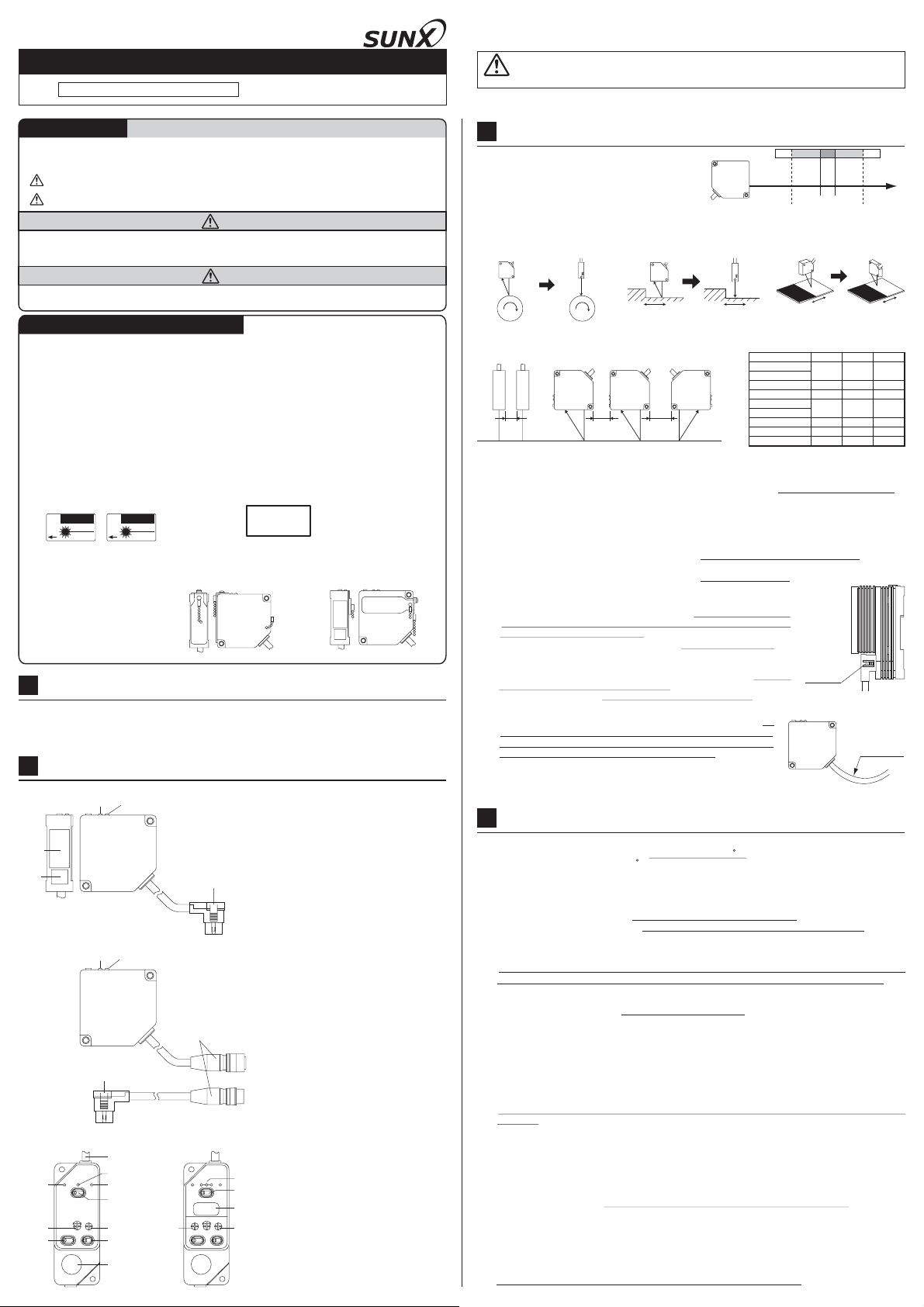
3
٨Procedure for setting the sensor head
While watching the measuring range indicator LED,
set the sensor head so that the distance to the subject body is within the measuring range.
It may light up or blink even with a significant error in
the measuring range when the alarm is enabled.
Be careful of the sensor head's orientation during mounting. When the subject body moves as shown below, er-
rors will develop depending on the orientation of the sensor head. In order to minimize these errors, be sure to
mount the sensor head in the correct orientation.
عEccentricity measurement عStep measurement ع
Not good
Not good
Confirm the mutual interference area when using sensors side
by side.
٨
Mounting the sensor head
Using two mounting holes, firmly mount the sensor head so that the sensor head's front surface is parallel to
the target. Do not tighten the installation screws to a torque over 2N䊶m
Glass is used at the sensor head's light emitting and light receiving surfaces and, therefore, never subject it to impacts of any kind. Also, be very careful not to allow oils, finger prints, or other substances that may refract the light, to get on the glass during mounting.
If light reflected off the target is then reflected off nearby objects or walls and then received by the sensor head,
the sensor head reading will be adversely affected. To prevent this, either further separate the sensor head or
apply a black delustering paint to prevent the unwanted reflection of light.
٨Mounting the controller
When mounting more than one controllers in a row, maintain at least 10m between each unit. Also, when
mounting the controller inside control panels or areas where the air is not properly ventilated, the controller will
cause the ambient temperature to rise. In these cases, ensure cooling facilities.
٨
Wiring
Perform all wiring by faithfully following the input and output circuit explanations
and documents that came with the instrument. Also, to protect the inner circuitry, arrange the lead wire that is not interconnected in a way so that it does not
come into contact with other lead wires.
When mounting or removing a connector, always first turn off the controller and
then begin operations.
All connectors are of the lock-on type. When connecting a connector, be sure to
securely insert it until it locks into place. When removing a connector, first press
in the lock release button on the connector side and then remove the connector.
After removing a connector, do not touch the terminals located inside.
Cable
٨
When the sensor head and controller are fixed and cables connected, do
not subject the cables to a pull of more than 29.4N. Have no bends in the
cables with a radius of less than 20mm. Also, do not bend a sensor head's
cable near where the cable is attached to the sensor head.
When the sensor head is to be moved while in use, do not have it so that
the sensor head's cable becomes bent. If the location is such that it cannot
be helped, we recommend purchasing the appropriate length extension
cable. (ANR12غ)
CAUTIONS
4
٨
Operating environment
Use in an ambient temperature between 0 to +50 (32 to 122 F). Store in a location where the temperature
stays between -20 to +70 (-4 to 158 F).
Use in an ambient humidity between 35 to 85% RH. Avoid use in locations with drastic humidity changes which
cause condensation.
Use in locations where the illuminance from incandescent lamps received at the light receiving surface is below
2,500 lx (ANR11غandANR12261), or below 3,000lx (ANR12501,
Also, locate the unit so that sunlight, does not directly hit the beam-receiving part.
When exceptional accuracy is required, mount a shielding plate or other type of shading mechanism.
The power supply voltage should be between 85 to 110% of the rated voltage.
Since the internal circuits may become damaged if an external surge voltage exceeds 500V [r(1.250)Ǵs
unipolar full-wave voltage], always use a surge absorber or surge absorbing element.
Keep the sensor head beam-emitting part and beam-receiving part surface clean and free of moisture, oil, finger prints, and other light refracting substances, and free of dust, dirt, and other light blocking substances.
When cleaning the glass surfaces, wipe with a soft cloth or lens cleaning paper.
Although the sensor head is of water proof construction, it does not mean that measurements can be taken underwater or in the rain. Moreover, the connectors are not watertight.
Do not use the unit in locations with flammable or corrosive gases, locations with excessive dust, locations
splashed by water, or locations subjected to vibrations or excessive shocks.
Since the controller contains molded resins, do not use in environments that contain, or where contact with,
benzene, thinners, alcohols and other organic solvents; and ammonia, caustic sodas, and other alkaline substances is possible.
٨
Noise precautions
The connector's metal portion is internally connected to the analog output GND. In order to prevent affects from
noise or damage to the internal circuits, be sure to insulate the metal portion with electrical tape or other means.
Mount the unit as far away as possible from high voltage lines, power lines, or devices that generate large switch-
ing surges.
Separate the sensor head cable wiring, high voltage circuit, and power circuit.
If there is much noise on the power supply, it will affect the analog output. In such cases, use a noise filter or
noise cut transformer.
٨Insulation resistance and voltage withstandability
Do not perform insulation resistance or withstand voltage tests between the connector's metal portion and input / outputs.
٨
Power supply
Select a power supply with a ripple voltage below 0.5V (P-P) and a current capacity above 0.3A.
In order to avoid high-frequency noises when using a commercially available switching regulator, be sure to
ground the frame ground (F.G.) terminal.
When using a power supply that uses a transformer, be sure to use an insulated transformer. When using an
autotransformer (single-wound transformer), it is possible to damage this unit or the power supply.
Do not turn the power on again within 10 sec.after turning the power off.
٨Warm-up time
Allow at least 30 minutes, after turning on the unit, for the unit to properly warm up.
Good
Range indicator LED
Good
cba
OFF OFFBlink BlinkON
Outside the measurable range
Center
Measurable range
Extremely different adjacent color or materials
Outside the measurable range
Not good
Model No. a b c
ANR11501
ANR11511
ANR11821
ANR11151
ANR12501
ANR12511
ANR12821
ANR12151
ANR12261
40 20 70
50 60 110
80 100 150
50 40 90
80 80 130
120 140 190
210 350 400
Lock release
button
R20mm or more
ANR12511, ANR12821, ANR12151).
Good
(Unit: mm)
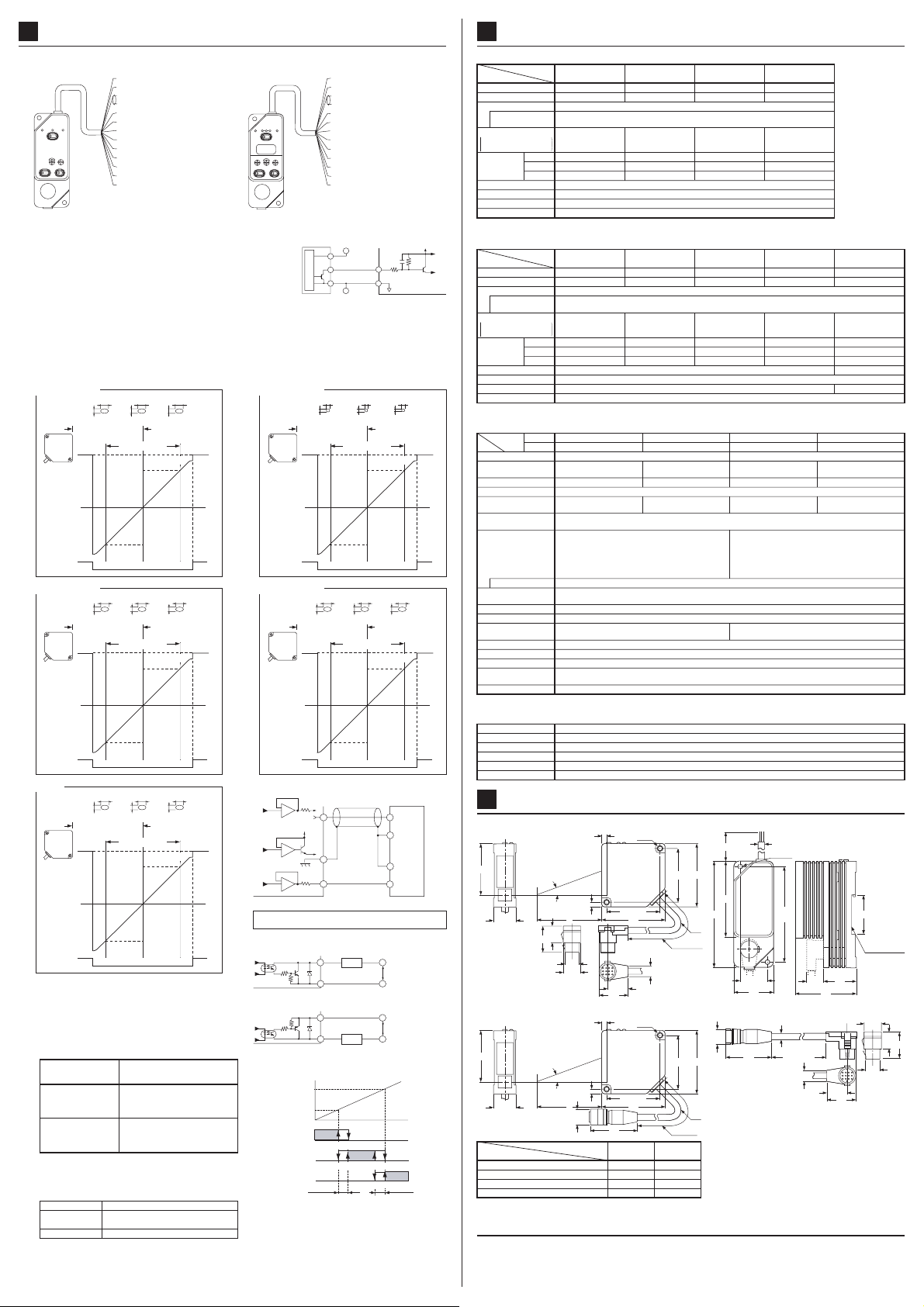
WIRING AND FUNCTIONS
5
٨Wiring
Single comparator type
MICRO LASER
SENSOR LM10
OPERATION
LASER BRT/DRK
DISPLACE
SET
MENT
ADJ
SET
+
-
SPEED(Hz)
GAIN
AUTO
LOW
Functions
٨
Power input [Brown (+), Blue (-)]
Input 12 to 24V DC.
Comparative timing input [Light blue]
While shorted to the 0V [Blue], comparative output is prevented. When using a
transistor to establish the timing, use a transistor with a residual output voltage of
1.5V or less during output.
Mutual interference prevention I/O [Green (input), Yellow (output)]
When using two sensors, you can set the mutual interference prevention mode by
connecting the input wire of each to the output wire of the other. Be aware that this
mode may adversely affect the linearity characteristics, resolution, and response.
Analog displacement output
An analog voltage / analog current (for each type separately) is is output that corresponds to the displacement of the target within the
measurement range. When the output selection switch is in the SET position, each comparative setting is outputted as voltage / current (for
each type separately).
㧖In case of window comparator type
㧙In both the voltage output and current output types, the LCD displays the voltage (r5V/F.S.).
㧙Between the current output type's analog displacement output and the LCD display, there is a maximum 3% of F.S. offset. Therefore,
exercise caution when aligning the 0 setting the comparative values.
ANR11501, ANR12501
Beam spot dia.
(mm)
Alarm
output
ANR11821, ANR12821
Beam spot dia.
(mm)
Alarm
output
ANR12261
Beam spot dia.
(mm)
Alarm
output
Intensity monitor output [red, shielding (GND)]
Analog voltage (-5V to +5V) is output corresponding to the amount of light
reflected from the target. If the amount of light increases, the voltage value
becomes larger and if it decreases, the voltage value becomes smaller.
Alarm output [orange, white (COM)]
Outputs during insufficient light (DARK) or too much (BRIGHT).
Comparative output
Single comparator type [black, gray, white (COM)]
ٟ
Displacement /
intensity comparative
selection input [Violet]
When not connected
When connected VQ0V
=Blue?
㧖For single comparator type
Connecting the violet wire and blue wire changes from the analog
displacement output to the light amount monitoring value output.
ٟ
Window comparator type [black, gray, violet, white (COM)]
Judgment result of analog displacement data is output.
LOW [violet]
IN RANGE [gray]
HIGH [black]
[Brown] 12 to 24V DC
[Blue] 0V
[White] Analog displacement output
[Shielding] Analog GND
[Red] Intensity monitor output
[Green]
Mutual interference prevention input
[Yellow]
Mutual interference prevention output
[Black]
Comparative output (FAR㧛LIGHT ON)
Comparative output (NEAR㧛DARK ON)
[Gray]
[White]
Comparative and alarm output
[Orange] Alarm output
[Violet]
Displacement / intensity comparative selection input
[Light blue] Comparative timing input
[white, shielding wire (GND)]
1.0
1.1
0.7
0.6
Measurement center
distance (50 mm)
Measuring range Measuring range
Min. 6
Displacement
output (V)
-10 +10
ON ON
1.3
0.8
0.7
Measurement center
distance (80 mm)
Measuring range Measuring range
Min. 6
Displacement
output (V)
-20 +20
ON ON
1.6
0.9
0.8
Measurement center
distance (250 mm)
Measuring range
Min. 6
Displacement
output (V)
-150 +150
ON ON
When displacement data is set value or over
(far side): FAR / LIGHT ON output is ON.
When displacement data is less than set value
(near side): NEAR / DARK ON output is ON.
When intensity data is set value or over
(near side): FAR / LIGHT ON output is ON.
When intensity data is less than set value
(far side): NEAR / DARK ON output is ON.
Outputs when below the set value's lower limit.
Outputs when between the set value's lower and
upper limits.
Outputs when above the set value's upper limit.
1.0
0.5
(Min. 21.6mA)
5
(20mA)
0
(12mA)
-5
(4mA)
OFF
1.2
1.2
0.6
(Min. 21.6mA)
5
(20mA)
0
(12mA)
-5
(4mA)
OFF
1.5
1.4
0.7
(Min. 21.6mA)
5
(20mA)
0
(12mA)
-5
(4mA)
OFF
Comparing operations
Distance
(mm)
Distance
(mm)
Distance
(mm)
Window comparator type
MICRO LASER
SENSOR LM10
HIGH
LOW
LASER
BRT/DRK
LOW
HIGH
SET
SET
DISPLACEMENT
V
ADJ
COM.
HIGHLOW
+
-
SPEED(Hz)
GAIN
AUTO
LOW
ANR11511, ANR12511
Beam spot dia.
(mm)
Alarm
output
ANR11151, ANR12151
Beam spot dia.
(mm)
Alarm
output
<Analog displacement output, intensity monitor output connection example>
(Voltage output type)
(Current output type)
Laser sensor
Note: Take care not to short-circuit between analog outputs or
apply voltage to them.
<Comparative output, alarm output connection examples>
NPN output type (ANR5XX1)
Laser sensor
PNP output type (ANR5XX2)
Laser sensor
<Description of comparative output operations>
Window comparator type
Set value's upper
limit (HIGH)
Set value's lower
limit (LOW)
LOW output
IN RANGE output
HIGH output
[Brown] 12 to 24V DC
[Blue] 0V
[White] Analog displacement output
[Shielding] Analog GND
[Red] Intensity monitor output
[Green]
Mutual interference prevention input
[Yellow]
Mutual interference prevention output
[Black]
Comparative output
[Gray]
Comparative output
[Violet]
[White]
[Orange] Alarm output
[Light blue] Comparative timing input
<Comparative timing input connection example>
㧗
Light blueޓ
Internal circuit
㧙
Photoelectric
sensor etc.
0.1
0.14
0.09
Measurement center
distance (50 mm)
Min. 6
Displacement
output (V)
-10 +10
ON ON
1.5
0.8
0.7
Measurement center
distance (130 mm)
Min. 6
Displacement
output (V)
-50 +50
ON ON
Analog displacement output
50ǡ
White
Shield wire
GND
Red
50ǡ
Intensity monitor output
Load
100mA
White
100mA
Load
White
Display
ONOFF
ONOFF
Hysteresis
(IN RANGE)
Comparative output
Comparative and alarm output
Blue
Laser sensor
0.05
0.13
0.08
(Min. 21.6mA)
5
(20mA)
0
(12mA)
-5
(4mA)
OFF
1.4
1.3
0.6
(Min. 21.6mA)
5
(20mA)
0
(12mA)
-5
(4mA)
OFF
GND
GND
Analog converter etc.
㧗
30V DC MAX.
㧙
㧗
30V DC MAX.
㧙
Displacement output
intensity (+)
ONOFF
ONOFF
Hysteresis
(HIGH)
(LOW)
COM.
Distance
(mm)
Distance
(mm)
SPECIFICATIONS
6
If there is no description for measurement conditions, the test is performed under operating voltage 24V DC, ambient temperature +20,
gain AUTO, response frequency 10Hz, interfernce prevention OFF and white ceramics as a target at a measurement center distance.
٨Sensor (ANR11 series)
Model No.
Item
Measurement center distance
Pulse width / Max. output
/ Laser class
Beam spot diameter
Representative values from a
measurement center distance
Resolution
(2ǻ)
Protection (excluding connector)
Ambient illuminance (Fluorescent lamp)
Note: White ceramics is the target of this value.
ANR11501 ANR11511 ANR11821 ANR11151
50mm 50mm 80mm 130mm
r10mm r10mm r20mm r50mmMeasuring range
0.61.1mm approx.
5Ǵm10Hz 5Ǵm20Ǵm 100Ǵm
16Ǵm100Hz 16Ǵm65Ǵm 330Ǵm
50Ǵm1kHz 50Ǵm 200Ǵm 1mm
Laser diode (Wavelength: 685nm)Light source
15Ǵs (Duty 50%) / 0.4mW (Peak value) / ClassΤ
0.090.05mm approx.
0.71.2mm approx. 0.71.4mm approx.
Within ᶠ0.2% of F.S.Linearity error (Note)
IP67 (IEC)
2,500lx or less
300g approx.Weight (including cable)
٨Sensor (ANR12 series)
Model No.
Item
Measurement center distance
Pulse width / Max. output
/ Laser class
Beam spot diameter
Representative values from a
measurement center distance
Resolution
(2ǻ)
Protection (excluding connector)
Ambient illuminance (Fluorescent lamp)
Note: White ceramics is the target of this value.
ANR12501 ANR12511 ANR12821 ANR12151 ANR12261
50mm 50mm 80mm 130mm 250mm
r10mm r10mm r20mm r50mm r150mmMeasuring range
0.61.1mm approx.
3.5Ǵm100Hz 3.5Ǵm13Ǵm65Ǵm 500Ǵm
10Ǵm1kHz 10Ǵm40Ǵm 200Ǵm 1.5mm
0.090.05mm approx.
1Ǵm10Hz 1Ǵm4Ǵm20Ǵm 150Ǵm
Sensor (including cable): 240g approx., Intermediate cable:130g approx.Weight (including cable)
Laser diode (Wavelength: 685nm)Light source
15Ǵs (Duty 50%) / 1.6mW (Peak value) / ClassΤ
0.71.2mm approx. 0.71.4mm approx. 0.81.5mm approx.
Within ᶠ0.2% of F.S.Linearity error (Note)
3,000lx or less
IP67 (IEC)
Within ᶠ0.4% of F.S.
2,500lx or less
٨Controller
NPN output
Model No.
Item
Analog output
Output impedance
Temperature drift
(Sensor and controller set)
Response frequency(-3dB)
Response time10 to 90%
Comparative output
Alarm output
Displacement display
Mutual interference prevention
Operation voltage range
Current consumption
(Sensor and controller set)
Note: The value of the linearity characteristics, resolutions and response time might get worse.
PNP output
ANR5131 ANR5141 ANR5231 ANR5241
ANR5132 ANR5142 ANR5232 ANR5242
Single comparator Window comparatorComparative output type
r5V/F.S.
(2mA max.)
50ǡ
Within r0.03% of F.S./ Within r0.04% of F.S./ Within r0.03% of F.S./ Within r0.04% of F.S./
<NPN output type>
NPN open collector 2 Nos.
(100mA 30V DC or less, residual voltage 1.5V or less)
<PNP output type>
PNP open collector 2 Nos.
(100mA 30V DC or less, residual voltage 1.5V or less)
<NPN output type> NPN open collector 1 No. (100mA 30V DC or less, residual voltage1.5V or less)
<PNP output type> PNP open collector 1 No. (100mA 30V DC or less, residual voltage1.5V or less)
Sensor: Measuring range display LED (RANGE)
(Note)
4 to 20mA/F.S.
(250ǡ max.)
㧙
Within r10% of F.S.Zero-point adjustment
1kHz / 100Hz / 10Hz
0.4ms / 4ms / 40ms (Switchable)
0.15% of F.S. or lessHysteresis
No voltage input (when earthing, no comparative output allowed)Comparative timing input
AUTO / LOW (switchable)Gain selection
Between 2 sets
㧗10
12 to 24V DCޓޓ%ޓincluding ripple 0.5V (P-P)
250mA or less (at 12V DC), 125mA or less (at 24V DC)
㧙15
180g approx.Weight (including cable)
r5V/F.S.
(2mA max.)
50ǡ
<NPN output type>
NPN open collector 3 Nos.
(100mA 30V DC or less, residual voltage 1.5V or less)
<PNP output type>
PNP open collector 3 Nos.
(100mA 30V DC or less, residual voltage 1.5V or less)
r5VIntensity monitor output
Sensor: Measuring range display LED (RANGE)
Controller: LCD 3 digit display
4 to 20mA/F.S.
(250ǡ max.)
㧙
٨Common
Insulation resistance (Initial)
Voltage withstandability (Initial)
Vibration resistance (Screw installation)
Shock resistance (Screw installation)
DIMENSIONS (Unit: mm)
7
٨Sensor (ANR11 series) ٨Controller
48
20.6
٨Sensor (ANR12 series)
48
20.6
Model No.
ANR11501, ANR11511, ANR12501, ANR12511
SUNX Limited
Head Office
2431-1 Ushiyama-cho, Kasugai-shi, Aichi, 486-0901, Japan Phone: +81-(0)568-33-7211 FAX: +81-(0)568-33-2631
Overseas Sales Dept.
Phone: +81-(0)568-33-7861 FAX: +81-(0)568-33-8591
Between external DC input and sensor metal parts (except for connector metal parts) 20Mǡ or more (at DC 500V megger)
Between external DC input and sensor metal parts (except for connector metal parts) AC 500V 1 min.
10 to 55Hz (1 cycle / min.) double amplitude of 1.5mm (sensor) / 0.75mm (controller), in X,Y and Z directions for two hours each
ǰ
5
h
15.8
25
13.3
16.5
ǰ
5
h
Ǿ14.7
Symbol
20G or more, in X,Y and Z directions for three times each
0 to 50, Storage: -20 to +70Ambient temperature
35 to 85% RH (No dew condensation)Ambient humidity
5 2-M5
50r0.2
19.2
28
60
11.8
50r0.2
Min. 2,000
Min.1,500
60
68.5
96
Ǿ6
٨Intermediate cable (ANR12 series only)
5 2-M5
50r0.2
60
43
h ǰ
50mm 20q
80mm 16qANR11821, ANR12821
130mm 11qANR11151, ANR12151
250mm 5.8qANR12261
50r0.2
Min. 500
Ǿ14
60
Ǿ6
Ǿ6
2-Ǿ4.5
86
r0.5
25r0.5
35
Ǿ6
43 Min.1,500
29(16)
55
11.8
19.2
28
http://www.sunx.co.jp/
35
Suitable for 35mm
width DIN rail
16.5
15.8
13.3
May, 2005PRINTED IN JAPAN
25
 Loading...