


User's Manual
http://www.nais-e.com/vision/
Panasonic...the new name for
Matsushita Electric Works, Ltd.

Before Reading This Manual
Thank you for purchasing the LightPixAE20.
In this manual, information on the hardware (installation, wiring, etc.) and the software (functions, setting
procedures, etc.) is described. Read this User’s Manual carefully before use.
Safety Precautions
To ensure that you use this product correctly, read this User’s Manual thoroughly before use. Make sure that
you fully understand the product and information on safe.
Conventions used in the Safety Precautions
Symbols:
The following symbols used in Safety Precautions.
Symbol Explanation:
WARNING
This indicates the existence of a hazard that could result in death of or serious damage to the operator, if
the safety instruction is not observed.
CAUTION
This indicates the existence of a hazard that could result in serious bodily injury or property damage, if the
safety instruction is not observed.
WARNING
• Do not use the product in the environment where combustible gas presents. This might cause
explosion.
• Never attempt to disassemble or alter the product. Failure to do so might result in an electric shock and
physical damage.
CAUTION
• Be sure to ground the product. Failure to do so might result in an electric shock.
• Do not touch the terminals while the power is on. This might result in an electric shock.
• Do not place heavy objects on the product. Do not use a heater near the product. This may result in
smoke coming from the product.
• Do not allow metallic objects or other flammable foreign matter inside the product. This might cause a
fire, electric shock or product damage.
• Use the product following the specifications. Failure to do so might result in abnormal heat and smoke
coming from the product.
• If you want to use the product for the purposes that are expected to lead to physical damage or serious
loss, safety measures, such as the installation of fail-safe systems, should be taken.

Table of Contents
Precautions before Use .................................................................................. iv
1. Overview of Light Pix AE20...................................................................... 1
1.1 Overview ...........................................................................................................2
1.2 Product Configuration........................................................................................ 3
1.3 Inspection Applications...................................................................................... 4
2. Names and Functions of Parts................................................................. 5
2.1 About the Main Unit........................................................................................... 6
2.2 Operation Unit ...................................................................................................7
2.2.1 Operation Unit...........................................................................................................7
2.2.2 Texts Displayed on the LCD Monitor of the Operation Unit....................................... 8
2.2.3 Lock Function............................................................................................................ 9
2.3 Finder Unit.......................................................................................................10
3. Installation and Wiring............................................................................ 11
3.1 A List of Connectable Units and Devices......................................................... 12
3.2 Connection between the Units......................................................................... 13
3.2.1 Connection the Main Unit to the Operation Unit......................................................13
3.2.2 Connection of the Operation and Finder Units ........................................................ 14
3.3 Fixing and Removing the Main Unit................................................................. 15
3.3.1 Main Unit ................................................................................................................. 15
3.3.2 Operation Unit......................................................................................................... 18
3.3.3 Finder Unit...............................................................................................................19
3.3.4 Installation Environment.......................................................................................... 20
3.4 Input/Output Cables for Connecting Power Supply Unit or External Devices ..21
3.4.1 Sequence of Input/Output Signals...........................................................................21
3.4.2 Input Signal .............................................................................................................22
3.4.3 Output Signal ..........................................................................................................23
3.4.4 Power Supply Unit and the Wiring...........................................................................24
3.4.5 Grounding the Main Unit .........................................................................................25
3.4.6 Comformity to the EMC standard............................................................................ 25
3.5 Serial (RS-232C) Port...................................................................................... 26
3.5.1 Connecting to the External Devices ........................................................................26
3.5.2 Wiring Method......................................................................................................... 27
4. Inspection Applications.......................................................................... 29
4.1 Overview .........................................................................................................30
4.1.1 Inspection Applications............................................................................................30
4.1.2 Inspection Time....................................................................................................... 31
i

4.2 Color Area and Color Judgement.................................................................... 32
4.2.1 Overview of Color Area........................................................................................... 32
4.2.2 Overview of Color Judgement................................................................................. 33
4.2.3 Setting Procedures and Modes............................................................................... 34
4.2.4 Setting up the LightPixAE20 in CONFIGURATION Mode....................................... 35
4.2.5 Teaching in TEACHING Mode................................................................................ 37
4.2.6 Setting Judgement Criteria in JUDGEMENT CRITERIA SETTING mode ..............41
4.2.7 Inspection Execution............................................................................................... 42
4.3 Color Pattern Matching.................................................................................... 44
4.3.1 Overview of Color Pattern Matching ....................................................................... 44
4.3.2 Setting Procedure and Modes................................................................................. 48
4.3.3 CONFIGURATION mode........................................................................................ 49
4.3.4 Teaching in TEACHING Mode................................................................................ 52
4.3.5 Setting Judgement Criteria in JUDGEMENT CRITERIA SETTING Mode ..............56
4.3.6 Inspection Execution............................................................................................... 57
4.4 Edge Detection................................................................................................ 59
4.4.1 Overview of Edge Detection....................................................................................59
4.4.2 Setting Procedure and Modes................................................................................. 61
4.4.3 Setting Up the LightPixAE20 in CONFIGURATION Mode...................................... 62
4.4.4 Executing a Teaching in TEACHING Mode ............................................................64
4.4.5 Setting Up the Judgement Criteria in JUDGEMENT CRITERIA SETTING mode... 68
4.4.6 Inspection Execution............................................................................................... 69
4.5 Peak Detection ................................................................................................70
4.5.1 Overview of Peak Detection.................................................................................... 70
4.5.2 Setting Procedure and Modes................................................................................. 72
4.5.3 Setting Up the LightPixAE20 in CONFIGURATION................................................ 73
4.5.4 Teaching in TEACHING Mode................................................................................ 75
4.5.5 Setting Up the Judgement Criteria in JUDGEMENT CRITERIA SETTING Mode... 79
4.5.6 Inspection Execution............................................................................................... 80
4.6 Measurement .................................................................................................. 81
4.6.1 Overview of Length Measurement.......................................................................... 81
4.6.2 Setting Procedure and Modes................................................................................. 84
4.6.3 Setting Up the LightPixAE20 in CONFIGURATION Mode...................................... 85
4.6.4 Setting a Minimum Value for a Mesurement Object................................................ 87
4.6.5 Teaching in TEACHING mode................................................................................ 88
4.6.6 Setting Up Judgement Criteria in JUDGEMENT CRITERIA and MEASUREMENT
OBJECT MIN. SETTING modes............................................................................. 92
4.6.7 Measurement Execution .........................................................................................93
4.7 Detailed Functions in CONFIGURATION Mode.............................................. 95
5. Parallel Communication..........................................................................99
5.1 Operations through Parallel Communication................................................. 100
5.1.1 Using Input Signals from External Devices........................................................... 100
5.1.2 Output Signals from the LightPix........................................................................... 100
5.2 Input/Output Timing....................................................................................... 102
ii

5.2.1 Performing a Reading Operation (Internal Trigger: OFF)......................................102
5.2.2 Switching Product Types.......................................................................................103
5.2.3 Swtiching to TEACHING Mode .............................................................................103
5.2.4 Teaching ...............................................................................................................104
6. RS-232C Communication ..................................................................... 107
6.1 Overview .......................................................................................................108
6.2 Command Format .........................................................................................110
6.2.1 Reading Data Area: RD ........................................................................................110
6.2.2 Writing in the Data Area: WD ................................................................................ 111
6.2.3 Notation Sytem for Data in Command/Response Messages ................................112
6.2.4 A List of Error Codes.............................................................................................113
6.3 Communication Conditions............................................................................ 114
6.4 A List of Data Registers for Each Application ................................................116
6.4.1 Color Area/Judgement ..........................................................................................116
6.4.2 Color Pattern Matching..........................................................................................119
6.4.3 Edge Detection......................................................................................................122
6.4.4 Peak Detection...................................................................................................... 125
6.4.5 Measurement ........................................................................................................128
7. About AETOOL and GT11 .................................................................... 133
7.1 AETOOL........................................................................................................ 134
7.1.1 Overview of AETOOL............................................................................................134
7.1.2 Obtaining and Installing the AETOOL ...................................................................135
7.1.3 Connecting to a Computer ....................................................................................135
7.2 GT11 136
7.2.1 Functions of GT11.................................................................................................136
7.2.2 Sample Data for GT11 ..........................................................................................136
7.2.3 Connection to the GT11 ........................................................................................ 137
8. General Specifications, Product Numbers and Dimensions............. 139
8.1 General Specifications................................................................................... 140
8.2 A List of Product Numbers.............................................................................142
8.3 Dimensions....................................................................................................143
Record of Changes ...................................................................................... 146
iii

Precautions before Use
Installation Environment
Avoid installing the LightPixAE20 in the following locations:
Locations with direct sunlight or environmental temperatures exceeding a range of 0ºC to +40ºC.
Locations with a relative humidity exceeding a range of 35%RH to 85%RH (without dew condensation
at 25ºC)
Locations with a lot of fine particles, iron filings, salt, oily smoke or conductive dusts.
Locations with an atmosphere containing corrosive gases or flammable gases.
Locations where the product can contact oil or chemicals.
Locations near organic solvents (such as benzene, paint thinner, and alcohol) or strongly alkaline
materials (such as ammonia and caustic soda)
Locations within 100mm of high-voltage wires (or devices), power-driven lines (or devices), radios,
transmitters and devices generating large switching surge (be sure to keep more than 100mm space
between the LightPixAE20 and these devices)
Power Supply
Take care not to generate excessive static electricity from the LightPixAE20.
When supplying power to the LightPixAE20, do not commonly use the power source for powering the
device and be sure to install a protection circuit such as a fuse.
Use an insulated power supply unit with a built-in protection circuit. The LightPixAE20 power supply
unit is a non-insulated circuit. Therefore, applying an abnormal voltage might damage the internal
circuit. If you use a power supply unit without a protection circuit, supply power through a protective
device such as a fuse.
About grounding
Do not commonly use the ground with other devices.
Grounding should be as close as the main unit as possible, and keep the distance short.
Noise Countermeasure
Do not bundle the optional cable connecting between the main unit and the operation unit, and input
/output signal cables connecting to the main unit together with motor or power cables. Ensure that they
are at least 100m apart. Keep the signal cables as short as possible.
If the external devices connected to the main unit are connected with directive conduction load (a motor
or relay), equip noise absorption elements such as noise killers at the load side.
Lighting equipment for image process generates signal of extremely high noise level due to high
frequency lighting. If you use external lighting, arrange the wiring of power transmission and signal
cables carefully.
Before Turning on the LightPixAE20
Pay attentions to the followings when turning on the LightPixAE20 for the first time;
Confirm no wiring waste or especially any conductive substance coming from installation is on the
printed circuit board
Confirm that the power voltage, power wiring and input/output wiring is correct.
Confirm that the fixing and terminal screws are securely tightened.
Do not turn the LightPixAE20 on within 10 minutes after turning the main unit off. This may result in
malfunction.
iv

General Cautions
Do not connect Ethernet to the connector on the operation unit for connecting the optional cable or the
port for connecting the operation unit.
Use the operation unit and finder unit of a product number specified by Matsushita Electric Works, Ltd.
A breakdown, damage or destruction by using any other than the specified will not be covered by our
guarantee.
Do not disassemble and remodel the LightPixAE20 or change its internal settings. A breakdown,
damage or destruction caused by disassembling, remodeling the LightPixAE20 or not following the
instructions described in the manuals will not be covered by our guarantee.
Do not change or set items that should not be as described in the manual or the specification.
Breakdown, damage or destruction resulting from changing or setting them will not be covered by our
guarantee.
To USA Customer
Products sold by Seller are covered by the warranty and patent indemnification provisions in its Terms
and Conditions of Sale only.
v

Chapter 1
Overview of Light Pix AE20
1

1.1 Overview
LightPixAE20 (hereinafter called “the LightPixAE20”) is a device that is integrated with CPU, camera, lens
and lighting equipment. With AETOOL software for the LightPixAE20 (free), you can download one of the
inspection applications to the main unit, check scanning conditions or images and document the images
stored in the main unit (or save them as bmp file).
In addition, with the operation unit and finder unit, you can check the current image or modify the scanning
conditions, and with our programmable display GT11, you can change settings or control start of code read.
The operating instructions mainly for the operation unit and finder unit are described in this manual.
Refer to the AETOOL help files (available after installation) for further details of the AETOOL.
About the AETOOL: Page 134
2
1.2 Product Configuration
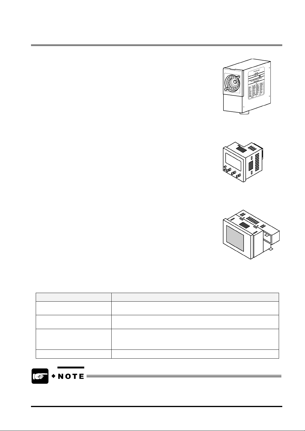
Main Unit
The LightPixAE20 is a device that is integrated with CPU, a camera and lighting
equipment. Inspections can be performed by using the main unit only. You can
download one of the inspection applications to the AETOOL. The LightPixAE20
has parallel I/O and serial RS-232C ports for communication with external
devices.
Operation unit
The operation unit has eight buttons and a display area (7-segment
negative/positive LCD display). With these buttons, you can make various
settings. In the display area, setting items and options are displayed. If the
device is connected to the main unit with the provided cable while scanning
codes, the detected data, results, and operation status of the main unit are
displayed in this area.
Finder Unit
The finder unit is a device that displays the images captured with the main unit.
Mount the device onto the operation unit before use. Do not directly connect the
finder unit to the main unit.
AETOOL*
The AETOOL is software exclusively for LightPixAE20. Before using this software, install it to the PC
connected to the LightPixAE20 with USB cable (AB type). The key features of this software are shown in
the table below.
Features Description
Transferring the inspection
application to the main unit
Setting up inspection conditions Carries out all of the operations you can perform with both the operation
Backing up configuration data
and downloading backup
configuration data
Documenting configuration data Writes out the backup configuration data in the CSV format.
You can freely download this software from our website.
"http://www.nais-j.com/vision/uacs"
Switches the applications for LightPixAE20
unit and the finder unit.
Backups the configuration data, saves files on PC and downloads the data
to the main unit. Thus, if you use multiple main units under the same
reading conditions, you can copy and use the data in individual main units.
3

1.3 Inspection Applications
There are six kinds of inspection applications available on the LightPixAE20. You can download one of the
following inspection applications to the main unit before use.
Inspection Applications
Type Overview
Color Area Measures the registered color area
Color Judgement Selects the color of the object from maximum seven registered
Color Pattern
Matching
Edge Checks whether or not the detected edges of the object move from the
Peak Finds out whether or not the detected vertices of the object move from the
Measurement Finds out whether or not the measured max./min. values in the horizontal and
The number of inspection applications that you can download is only one.
Refer to section 4, “Inspection Applications“(page 30) for the details of each inspection application.
In a color extraction image, detects the same image as the saved base image
(template)
registered base position
register base position
vertical directions are equal to the registered base size
4

Chapter 2
Names and Functions of Parts
5
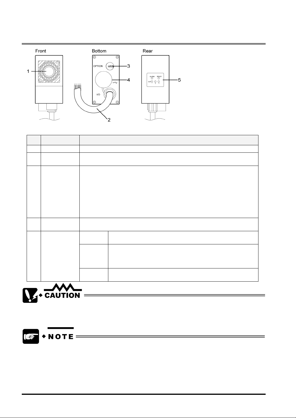
2.1 About the Main Unit
Designations and Descriptions of Each Part
No. Name Description
1 Capture part Camera for capturing images, lens and white LED are built in this part.
2 I/O cable This external input/output cable used for supplying 24 VDC, inputting scan start
3 Optional cable
connector
(for connection
to the operation
unit and for
RS232C)
4 USB port This port is used for connecting to the PC in which AETOOL is installed. Use a AB
5 LED indicators
TRIGGER signal and outputting inspection result signal.
Port used for connecting to the operation unit and to external devices such as PLC,
our programmable display GT11, etc. through RS-232C communication.
Select a proper optional cable for your connecting equipment.
• When connecting to operation unit (plus finder unit), use the optional cable
ANE2813.
• When connecting to external devices through RS-232C communication,
use the optional cable ANE2803.
• In the both cases above, use the optional cable ANE2823.
type cable for USB2.0 or 1.1 (max. cable length: 5m)
OUT1 - 3 Output state of inspection results. The OUT1-3 LEDs goes on when
each signal is output.
READY The READY LED goes on when the main unit performs no process.
The LightPixAE20 can receive inspection start signal (TRIGGER
signal in RUN or RUN VIEW mode) from the external devices only
while the READY signal is being output.
ALARM The ALARM LED goes on when the LightPixAE20 could not finish
teaching properly.
Use only the specified cable and device for the optional cable connector and USB port respectively.
Failure to do so may result in product damage.
• If the ALRAM signal is output when teaching is finished properly, reboot the LightPixAE20.
In the case of frequent output of the ALARM signal, the LightPixAE20 may be broken. Please
contact us.
• Expected service life of the white LED built in the main unit is 30,000 hours. (Light intensity drops
to 50 % under the conditions of high-speed operation at 25ºC while internal trigger is ON.) It is
advisable to make regular adjustment for light intensity and carry out a re-teaching, because
lower light intensity may negatively affect the measurement results.
6
2.2 Operation Unit
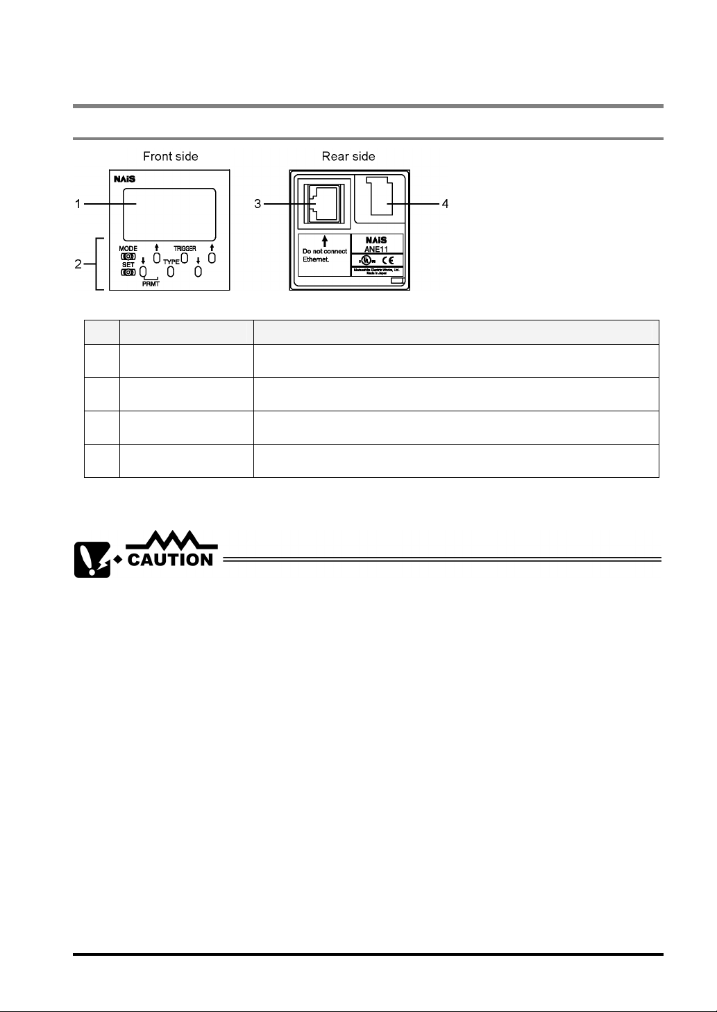
2.2.1 Operation Unit
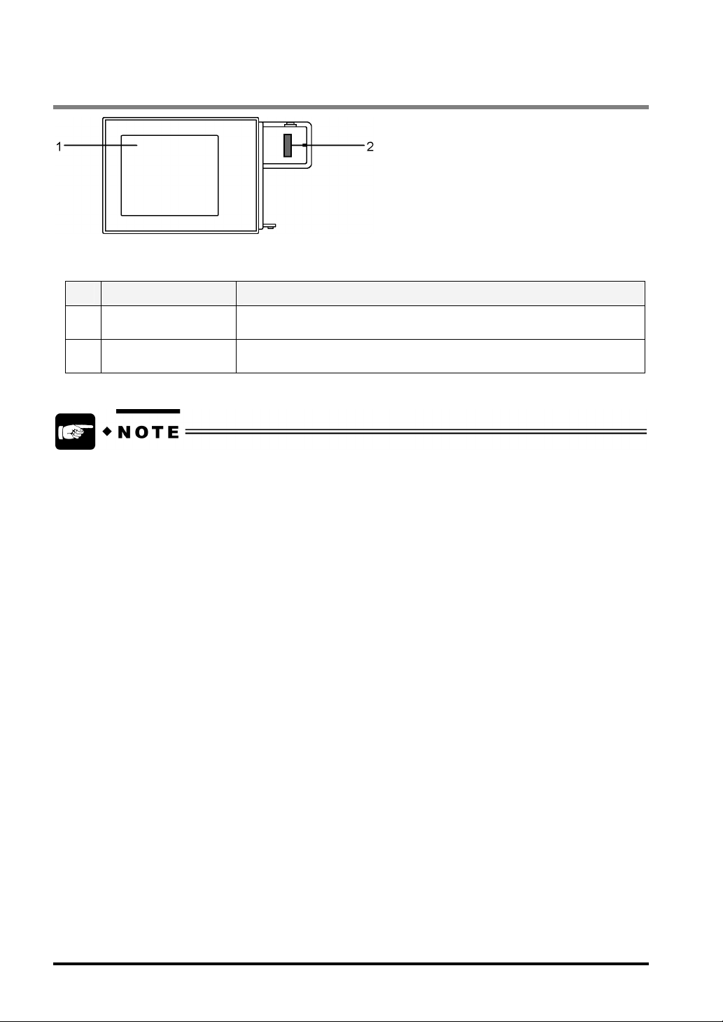
Designations and Descriptions of Each Part
No. Name Description
1 Display area Operation status of main unit, modes, inspection results and setting items are
2 Operating buttons Used for operating the main unit. There are eight operating buttons.
displayed in the display area. Refer to the next page for further details.
3 Port for connecting to
the main unit
4 Connector for finder
unit
Do not connect any other device to the port for the main unit. Failure to do so may result in product
damage.
Used for connecting to the main unit. Use the cable ANE2813 or ANE2823 to
connect to the main unit.
Used for connecting to the finder unit
7

2.2.2 Texts Displayed on the LCD Monitor of the Operation Unit
The display area of the operation unit displays measurement data and setting values and operating status of
the LightPixAE20 as a text string.
Displayed
text
SET CONFIGURATION mode Indicates the LightPixAE20 is in CONFIGURATION mode
RUN RUN (RUN VIEW) mode Indicates the LightPixAE20 is in RUN mode.
TEACH TEACHING mode Indicates the LightPixAE20 is in TEACHING mode.
Mode Description
VIEW RUN VIEW mode Indicates the LightPixAE20 is RUNVIEW mode. In this mode,
READY RUN (RUN VIEW) mode
LOCK RUN (VIEW) mode Means the lock function is activated. In this mode, you cannot
ALARM
(Red)
OUT1-3 RUN (RUN VIEW) mode Represents output state of parallel output signals OUT1-3. The
mm RUN (RUN VIEW) mode Indicates the unit for the measured data is millimeter. You can
mm2 RUN (RUN VIEW) mode Indicates the unit for the measured data is square millimeter.
TEACHING mode
RUN (VIEW) mode
TEACHING mode
(May be displayed when the
device is in the other
modes.)
captured images are displayed on the finder unit.
Displayed when parallel output signal “READY” is ON.
operate the LightPixAE20.
Displayed when the parallel output signal “ALARM” is ON.
signals that are turned on are displayed.
For example,
• OUT 1 2: OUT1 and OUT2 signals are on.
check it only if you are using the following applications:
• Color Pattern Matching
• Edge
• Peak
• Measurement
You can check it only if you are using the following applications:
• Color Area
• Color Judgement
8
2.2.3 Lock Function
The LightPixAE20 comes with a built-in Lock function that helps you avoid accidental operation of the
operation unit (if connected). As long as this function is activated, the current operation mode and settings of
the LightPixAE20 are not changed even if the operating buttons are accidentally pressed.
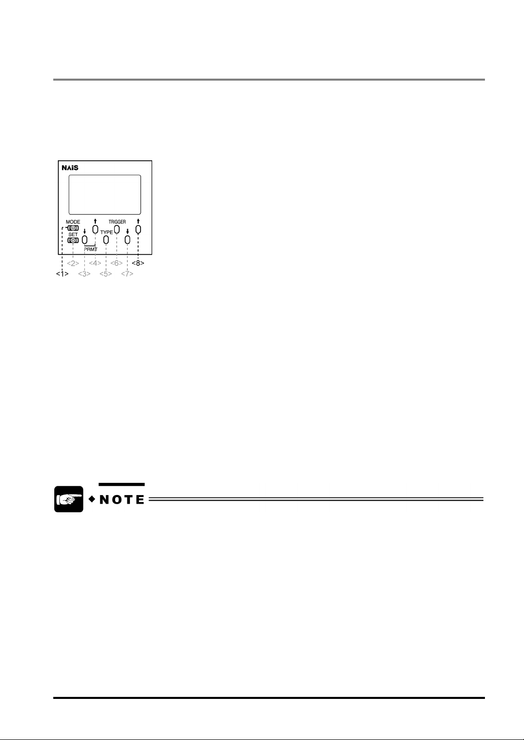
Buttons to be used for setting the Lock function
To lock the operation unit:
1. Press the buttons 1 and 8 on the operation unit at the same time for approximately three
seconds.
The word “Lock” appears on the LCD display (refer to the previous page for details of displayed texts).
To unlock the operation unit:
1. Press the buttons 1 and 8 on the operation unit at the same time for approximately three
seconds.
The word “Lock” disappears.
Even when locking the operation unit, you can input signals from AETOOL or external devices, or
change settings and switch modes via RS-232C communication.
9
2.3 Finder Unit
Designations and Descriptions of Each Part
No. Name Description
1 Image display area A captured image is displayed when the LightPixAE20 is in RUN-VIEW
mode. (Images are not displayed in RUN mode.)
2 Connecting connector Used for connecting the operation unit.
Expected service life of the backlight is approx. 40,000hours (at operating ambient temperature
25ºC). The LightPixAE20 comes with a built-in Backlight OFF-TIMER function. This function would
be helpful if you want to turn the device off in 10, 30 or 60 minutes. Refer to Section 4.7, “Detailed
Functions in CONFIGURATION Mode” for more details of Backlight OFF-TIMER function.
10

Chapter 3
Installation and Wiring
11
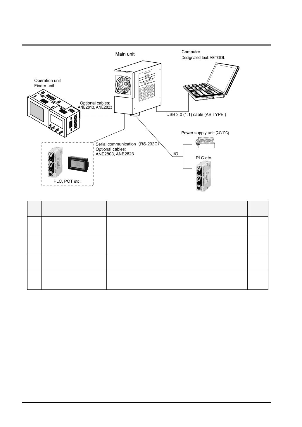
3.1 A List of Connectable Units and Devices
No. Connectable unit/device Purpose
1 Operation unit and finder
unit
To set inspection conditions and display images 13
Ref.
Page
2 I/O – power supply unit and
PLC
3 Serial (RS232C) – PLC,
POT, etc.
4 AETOOL installed PC To perform all operations without using the operation unit and
To control the LightPixAE20 with external devices such as
power supply unit and PLC and import measurement results.
To receive inspection results, control the LightPixAE20 by
sending commands from external devices and import
measurement results.
finder unit.
12
15
26
135
3.2 Connection between the Units
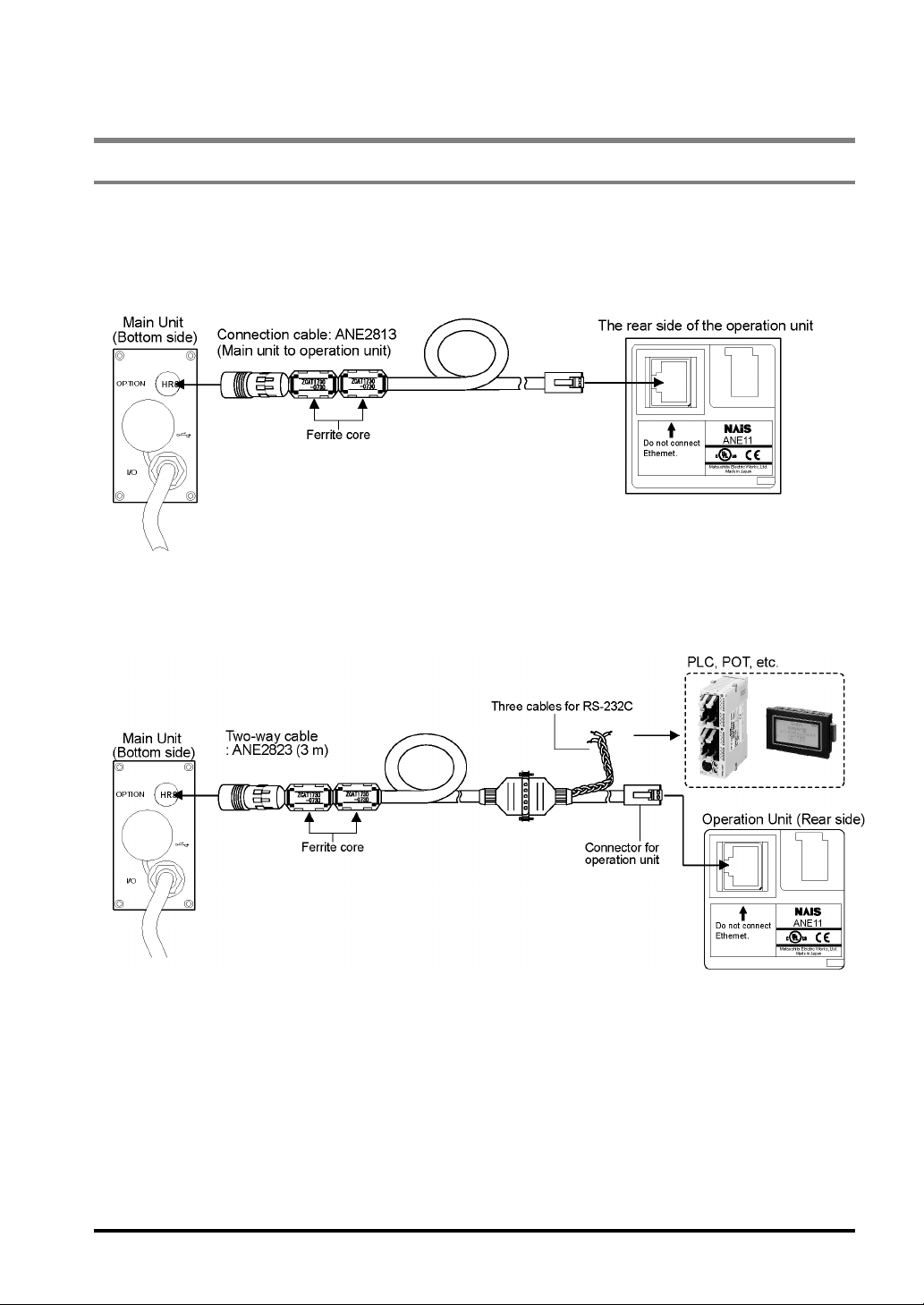
3.2.1 Connection the Main Unit to the Operation Unit
Use only the specified cable ANE2813 (cable length: 3m) or ANE2823 (cable length: 3m) to connect the main
unit to the operation unit.
When connecting to only the operation unit (with the finder unit)
When connecting the main unit to the operation unit (with the finder unit) and to the
external devices such as PLC and POT via RS-232C
13
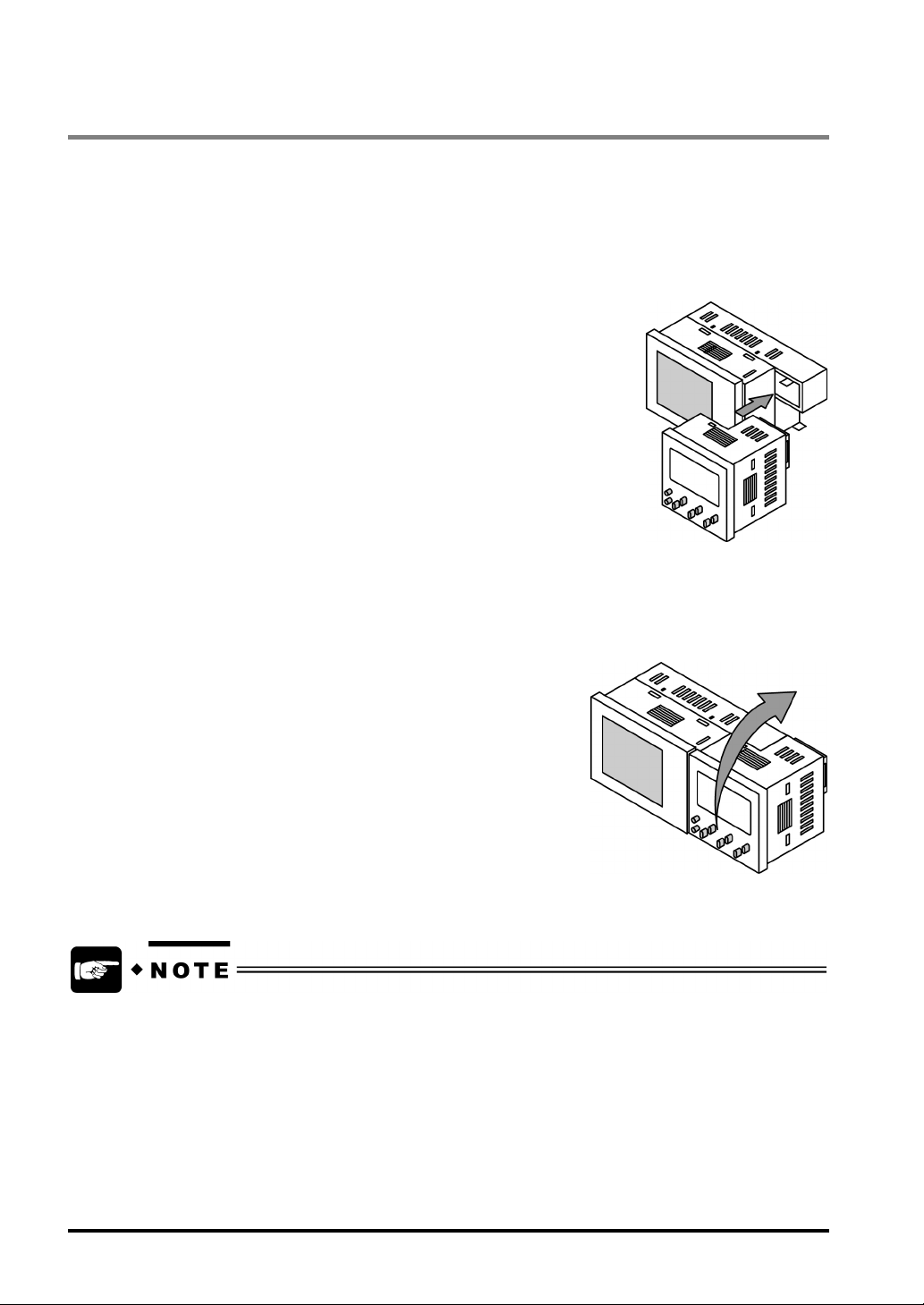
3.2.2 Connection of the Operation and Finder Units
You can mount the finder unit on the operation unit without using any cables. Use the connector for
connecting the operation unit or finder unit on each unit.
To mount the operation unit on the finder unit:
1. Insert the operation unit into the finder unit until it clicks.
To remove the operation unit from the finder unit:
1. Hold the finder unit with one hand.
2. Hold the operation unit with the other hand and lift the operation unit in the arrow direction.
• When using the finder unit, mount the operation unit on the finder unit first and connect the
devices with the optional cable for connecting to the main unit
• Do not mount the operation unit on the finder unit while the operation unit is running. Failure to do
so may result in the product damage.
14
3.3 Fixing and Removing the Main Unit
3.3.1 Main Unit
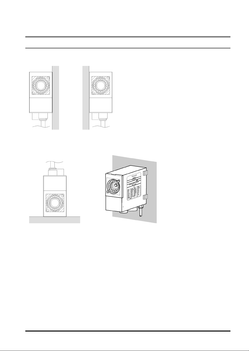
Fixing the main unit on a wall
Use the three holes on a side of the main unit to fix it on a wall.
Avoid installing the main unit as the following figures shown below.
Wrong Examples
15
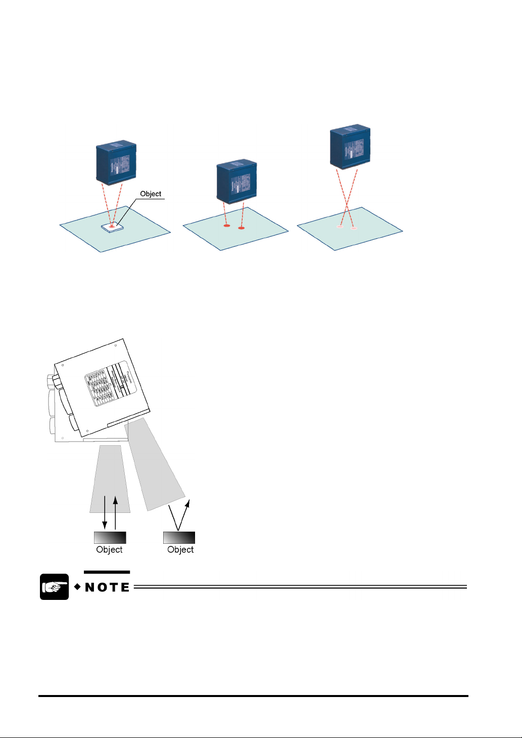
Installation distance between the main unit and the inspection object
Keep 15 to 220 mm space between the object and the main unit, but the space varies depending on the
product number of the main unit. Since light guides (two red LED lights) are emitted from the LightPixAE20
to the area around the object, adjust the position of the main unit so that the two lights are close (or overlap)
each other.
Proper Too close Too far
(Dim light guides)
Installation angle
If you want to capture a shiny object, the light emitted from white LED may interfere with the object due to
the mirror reflection from it, so slant the main unit.
16
• Disturbance light, of which illumination intensity varies at the time of measurement, negatively
affects the measurement results. Shield the device from any disturbance light.
• The larger the installation angle, the greater the warp generated in the captured mages. This will
lead to mixed measurement results depending on the position of the object within the field of
view. Determine the installation angle of the main unit after actually checking the image.
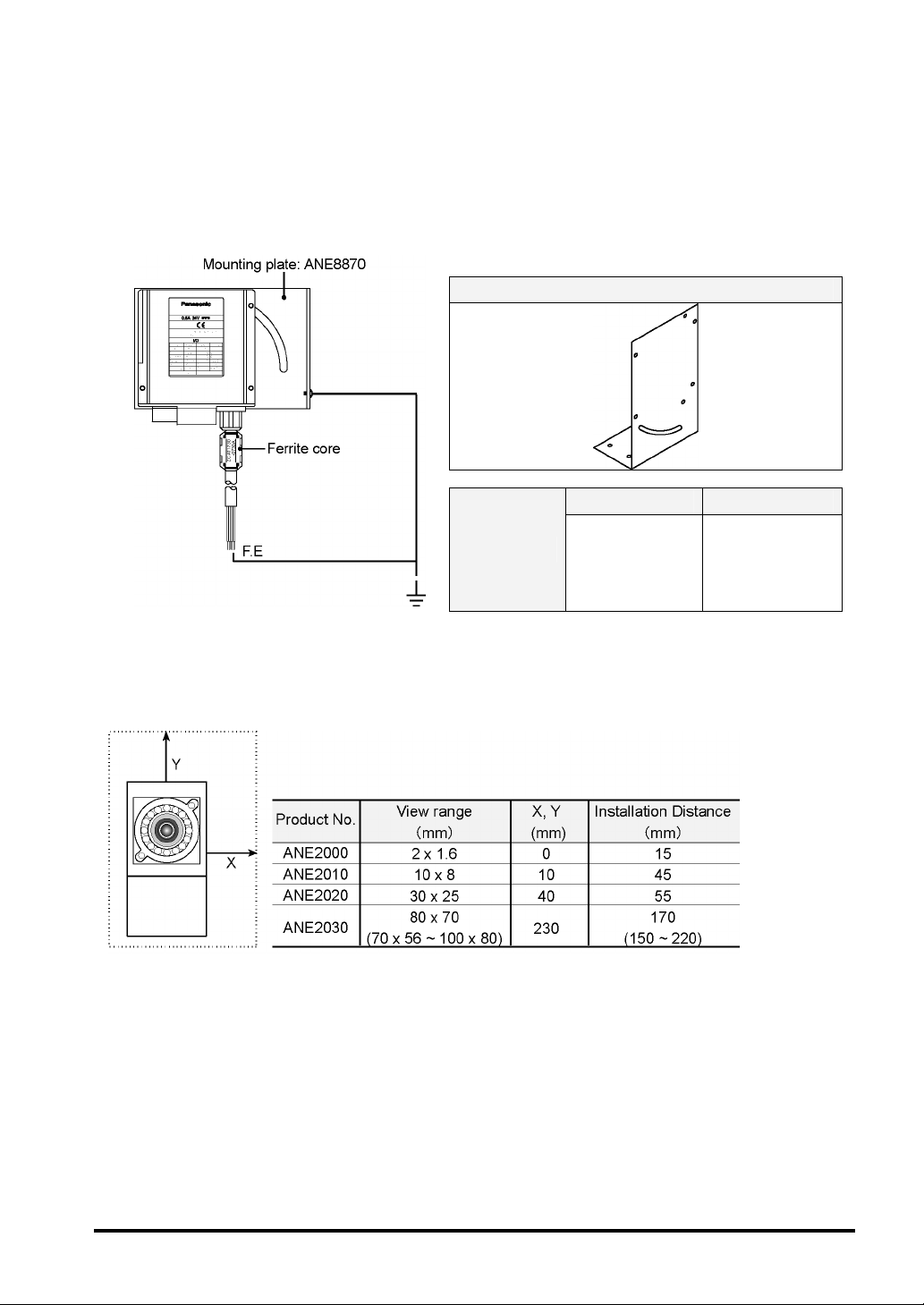
Conformity to the EMC standard
The AE20 will comply with the EMC standards (EN61000-6-4, EN61000-6-2) in EMC Directive (EMC
Directive 89/336/EEC). The product must fulfill the following conditions:
1. No USB communication
2. Ferrite core must be used for the wirings as the figures shown below.
3. Mounting plate ANE8870 (separately sold) must be used for grounding.
Mount Plate - Product No. ANE8870
Manufacturer Product No.
Ferrite Core
TDK CO., LTD. ZCAT1730-0730A
Installation space between the multiple units
Keep the enough space between the units to prevent the lights emitted from each unit from interfering with
each other (see the table below).
17
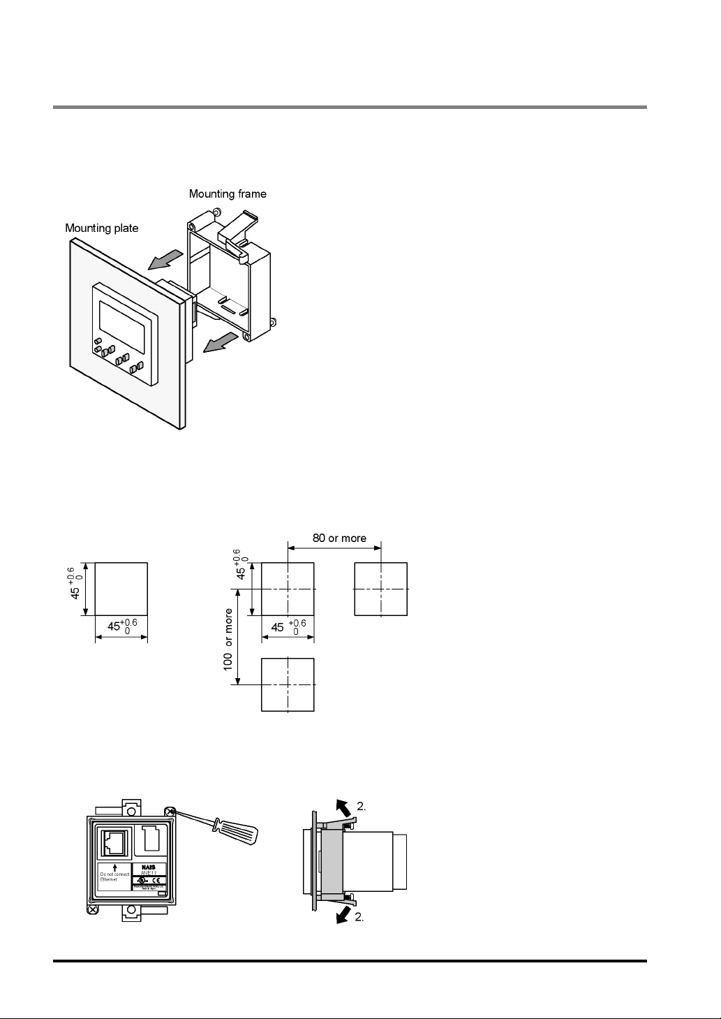
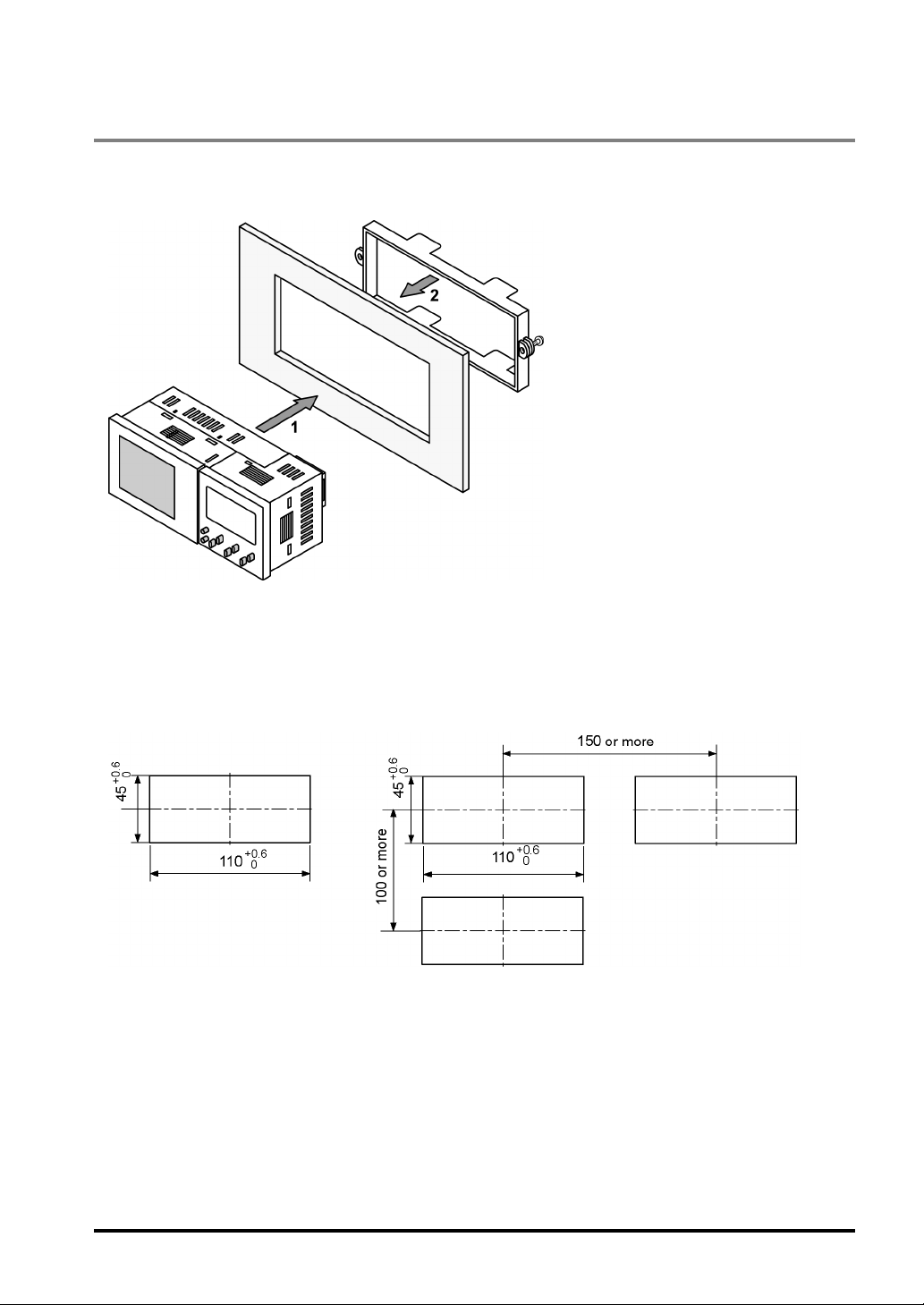
3.3.2 Operation Unit
Installing the operation unit only
Mount the operation unit onto the front side of the mounting plate, insert the mounting frame into the rear
side of the operation unit, then tighten the mounting frame with the screws.
Sizes of the mounting plate
Use 1 to 5mm thick panel.
To install a single unit: To install multiple units:
To remove the operation unit:
1. Loosen screws.
18
2. Remove the mounting frame while
pulling the tabs in the arrow directions.
3.3.3 Finder Unit
To mount the finder unit:
Assemble the operation unit first, mount the finder unit onto the front side of the mounting plate, and then
insert the mounting frame into the rear side of the fixing plate.
Sizes of the mounting plate
Use 1-5mm thick panel.
To install a single unit: To install multiple units:
19
3.3.4 Installation Environment
Installation Environment
Avoid installing the LightPixAE20 in the following locations:
Locations with direct sunlight or environmental temperatures exceeding a range of 0ºC to +40ºC.
Locations with a relative humidity exceeding a range of 35%RH to 85%RH (without dew condensation
at 25ºC)
Locations with a lot of fine particles, iron filings, salt, oily smoke or conductive dusts
Locations with a lot of dusts, oily smoke, conductive dusts, or corrosive or flammable gases
Locations where the product can contact oil or chemicals
Locations near organic solvents (such as benzene, paint thinner, and alcohol) or strongly alkaline
materials (such as ammonia and caustic soda)
Locations within 100mm of high-voltage wires (or devices), power-driven lines (or devices), radios,
transmitters and devices generating large switching surge (be sure to keep more than 100mm space
between the LightPixAE20 and these devices)
Noise Countermeasure
Do not bundle the optional cable connecting between the main unit and the operation unit, and input
/output signal cables connecting to the main unit together with motor or power cables. Ensure that they
are at least 100m apart. Keep the signal cables as short as possible.
If the external devices connected to the main unit are connected with directive conduction load (a motor
or relay), equip noise-absorbing elements such as noise killers at the load side.
Lighting equipment for image process generates signal of extremely high level due to high frequency
lighting. If you use external lighting, arrange the wiring of power transmission and signal cables
carefully.
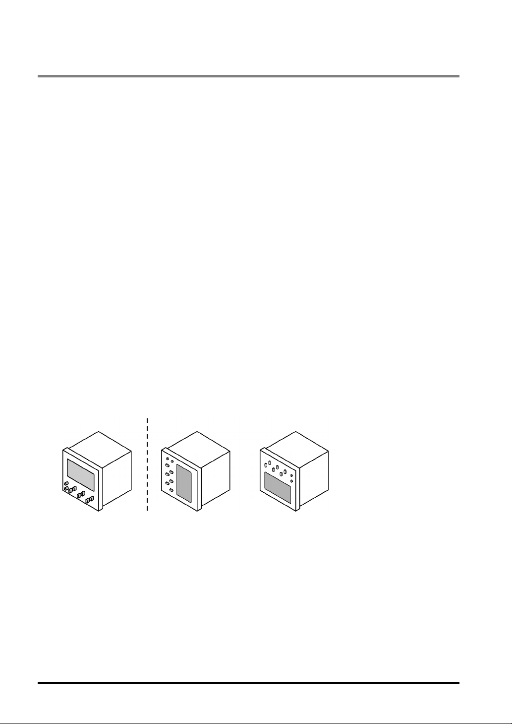
Countermeasure for Heat Radiation
When installing the operation unit (or the operation unit with finder unit), set the device in the following
direction for heat radiation.
Correct Wrong
20
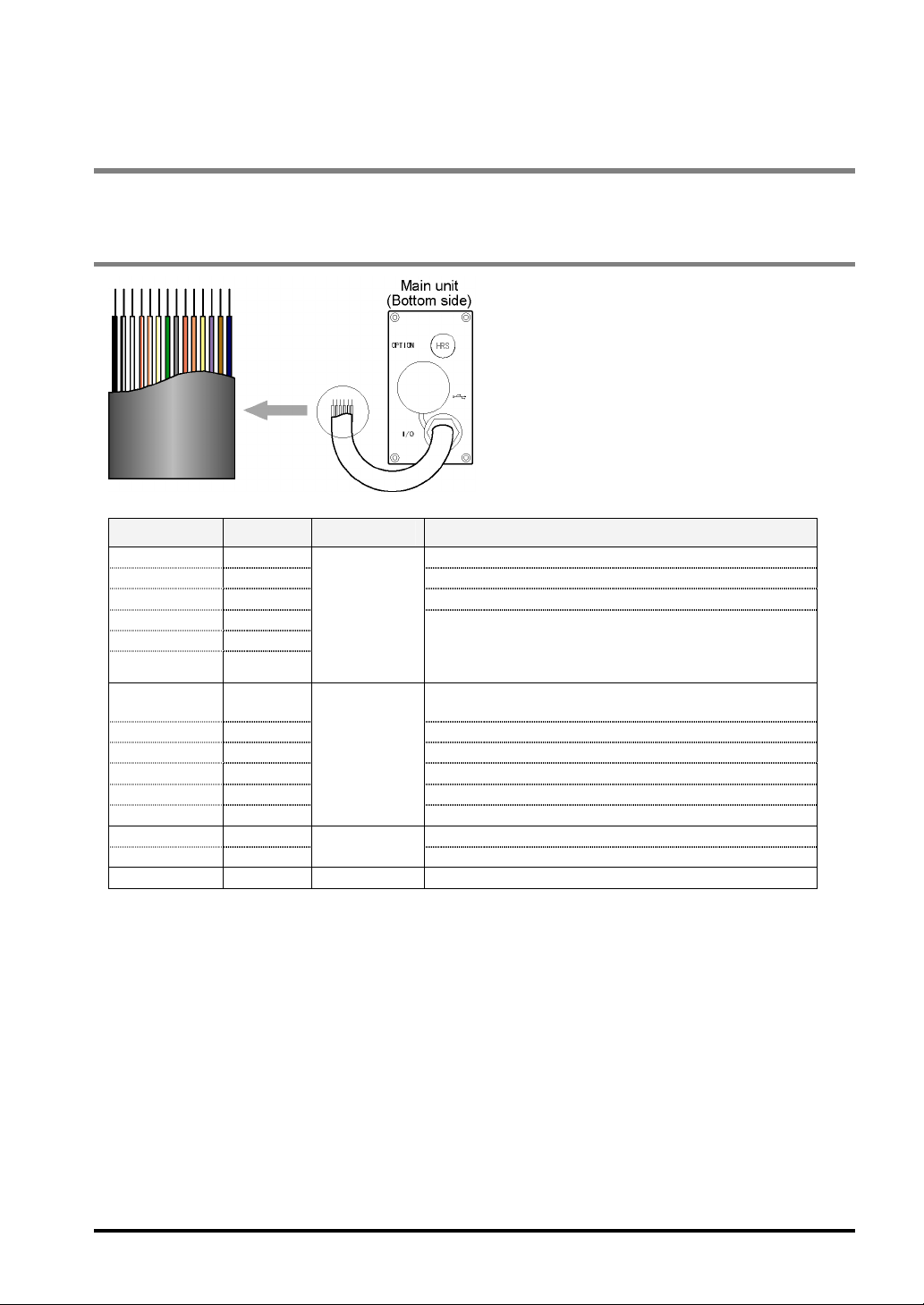
3.4 Input/Output Cables for Connecting Power Supply Unit or External Devices
The cables for connecting to the power supply unit or external devices are attached on the LightPixAE20.
3.4.1 Sequence of Input/Output Signals
Color Signal Input/Output Description
White COM (IN) COM for input
Red TRIGGER Read start signal
Gray TEACH Switching from TEACHING mode to RUN mode
Orange TYPE1
Yellow TYPE2
Purple TYPE3
White/ Black COM
(OUT)
Black READY Ready completion signal
White/Yellow ALARM Alarm signal
White/Brown OUT1 Judgement result output 1
White/Red OUT2 Judgement result output 2
White/Orange OUT3
Brown 24 V 24 V DC +
Blue GND
Frame F.E. - Functional earth
Input
Output
Power supply
Specifies product type number for switching product
types
(Binary input: Specify the number subtracted one from
the product number.)
COM for output
Judgement result output 3
24 V DC -
21
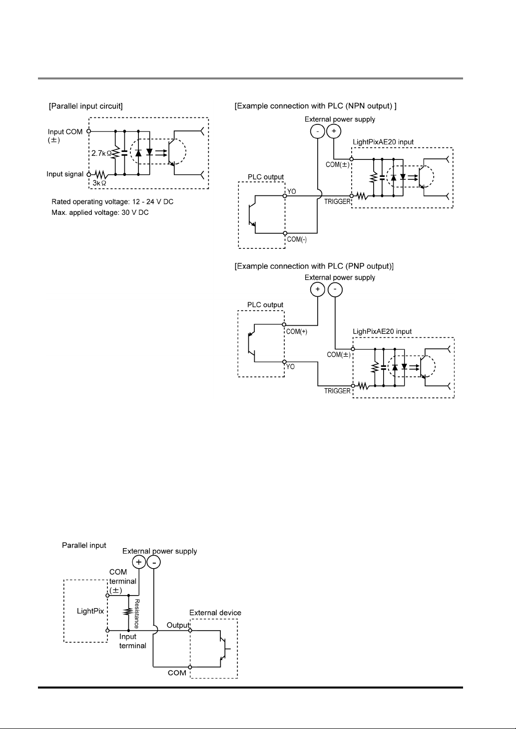
3.4.2 Input Signal
Circuit
Notes on Parallel Input
• To prevent input signal chattering, use a non-contact input (transistor etc.). If chattering occurs, inputs
may be missed or input recognition may be delayed.
• Be careful when using only full-wave rectification (including ripples) power supply for DC input, as it
may cause abnormal operation.
• Current leakage at the input side may not turn input off. In such as case, connect a resistor following
the figure below.
• If Input to the LightPixAE20 is not turned off due to current leakage when 2-line photoelectric sensor (or
proximity sensor) is used, connect a bleeder resistor.
• Even in cases where in-line LEDs such as LED reed switches are connected with an input contact
point, Voltage more than the ON voltage must be applied to the LightPixAE20 input terminal.
22
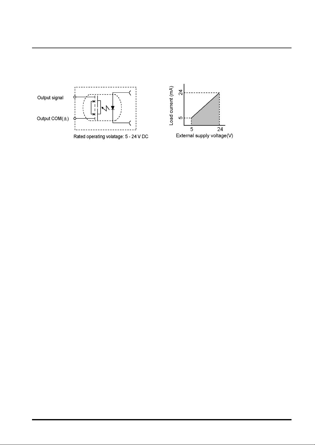
3.4.3 Output Signal
Circuit
Output part: PhotoMos relay
The output load should be within the specified range. See the figure shown below.
Notes on Parallel Output
• Leakage current at the time of output signal OFF is less than 100 µA.
• The LightPixAE20 has a low load capacity so that you can connect the LightPixAE20 to a PLC, etc. Do
not connect directly with a device having a high load capacity such as a valve without passing it through
our Power-Photo relay.
• The output circuit contains no built-in fuse. If it is necessary to prevent from burning out the output
circuit in the event of output load short circuit, mount a fuse externally. However, it may not be able to
protect internal elements in the event of short circuit.
23
 Loading...