

ICs for TV
AN8946SB
FM demodulation IC for BS/CS broadcasting
■ Overview
The AN8946SB is a 5 V single power supply and low
power consumption FM demodulation IC for BS/CS broadcasting. It features PLL · FM demodulation, 2nd IF AGC
amp., AGC detection and AFC (applicable to both mean
value and keyed types).
■ Features
• 5 V single power source
• Low power dissipation (typ. 170 mW)
• S/N 65 dB or more
• Inter-modulation interference ratio: 50 dB or more
• AGC amp built in (Reduction range: 55 dB)
• Adjustment-free VCO coil
■ Applications
• BS/CS tuner, television
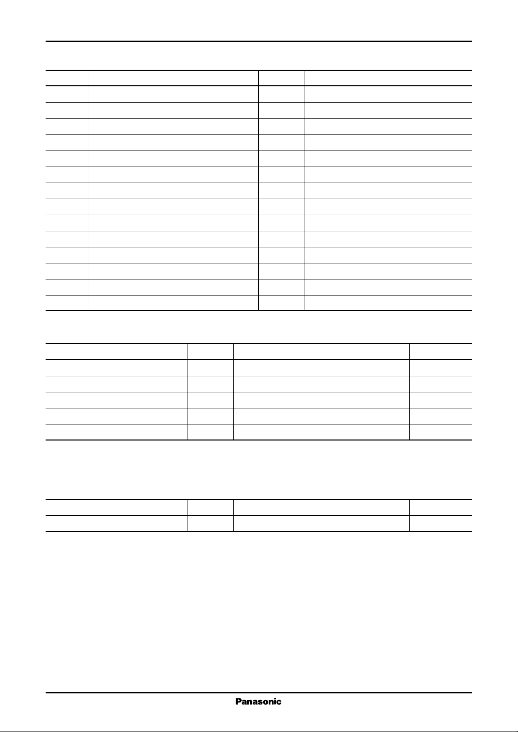
■ Block Diagram
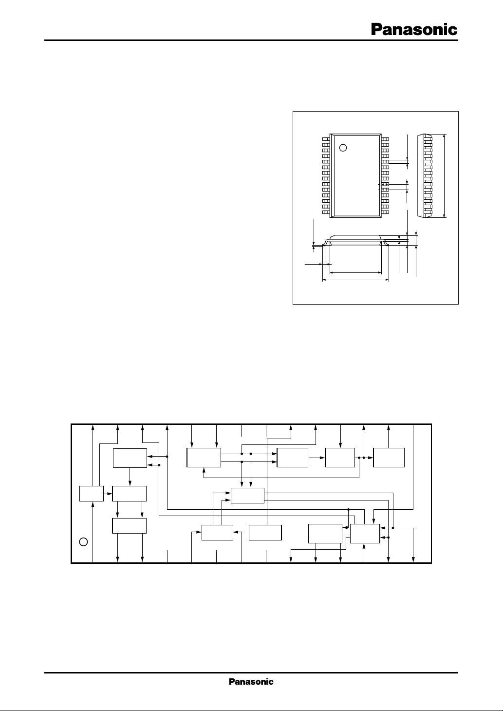
14
0.1±0.1
(0.4)
1
7.2±0.3
9.3±0.3
SSOP028-P-0375A
28
15
+0.1
–0.05
0.2
0.3±0.1
0.8
0.9±0.1 0.9±0.1
Unit : mm
11.6±0.3
2.05±0.2
28
27
AFC
amp.
Key Comp.
Latch
1
2
26
3
25
4
CC
V
5 V
Reg. out
24
AGC
amp.
23
22
GND
21
20
IF
amp.
2.6 V
19
18
DC
amp.
17
16
DC
amp.
15
PD
11
Loop
amp.
12
13
14
VCO REG
5
CC
5 V
V
6
GND
7
8
GND
Video
amp.
9
10
1
AN8946SB ICs for T V
■ Pin Descriptions
Pin No. Description
1 Key pulse input
2 AFC output L
3 AFC output H
4V
(VCO, AFC system)
CC2
5VCO1
6 GND3 (VCO system)
7 VCO2
8 GND2 (Main)
9 Loop amp. output
10 Video amp. input
11 Video amp. output
12 Free-run frequency adjustment
13 Loop amp. input 1
14 Loop amp. input 2
Pin No. Description
15 AFC adjustment
16 AGC output 2
17 AGC output 1
18 AGC adjustment
19 IF amp. output
20 Regulator output
21 V
CC1
(Main)
22 GND1 (AGC amp., regulator system)
23 IF amp. input 2
24 IF amp. input 1
25 AFC output R
26 AFC LPF2
27 AFC LPF1
28 Key pulse LPF
■ Absolute Maximum Ratings
Parameter Symbol Rating Unit
Supply voltage V
Supply current I
Power dissipation P
Operating ambient temperature
Storage temperature
Note) 1. Be carefl for static electricity damage of pin 1 to pin 5, pin 7, pin 21, pin 26 and pin 28.
: Except for the operating ambient temperature and storage temperature, all ratings are for Ta = 25°C.
2. *
*
*
CC
CC
D
T
opr
T
stg
5.6 V
50 mA
280 mW
−20 to +75 °C
−55 to +150 °C
■ Recommended Operating Range
Parameter Symbol Range Unit
Supply voltage V
CC
4.5 to 5.5 V
2
ICs for TV AN8946SB
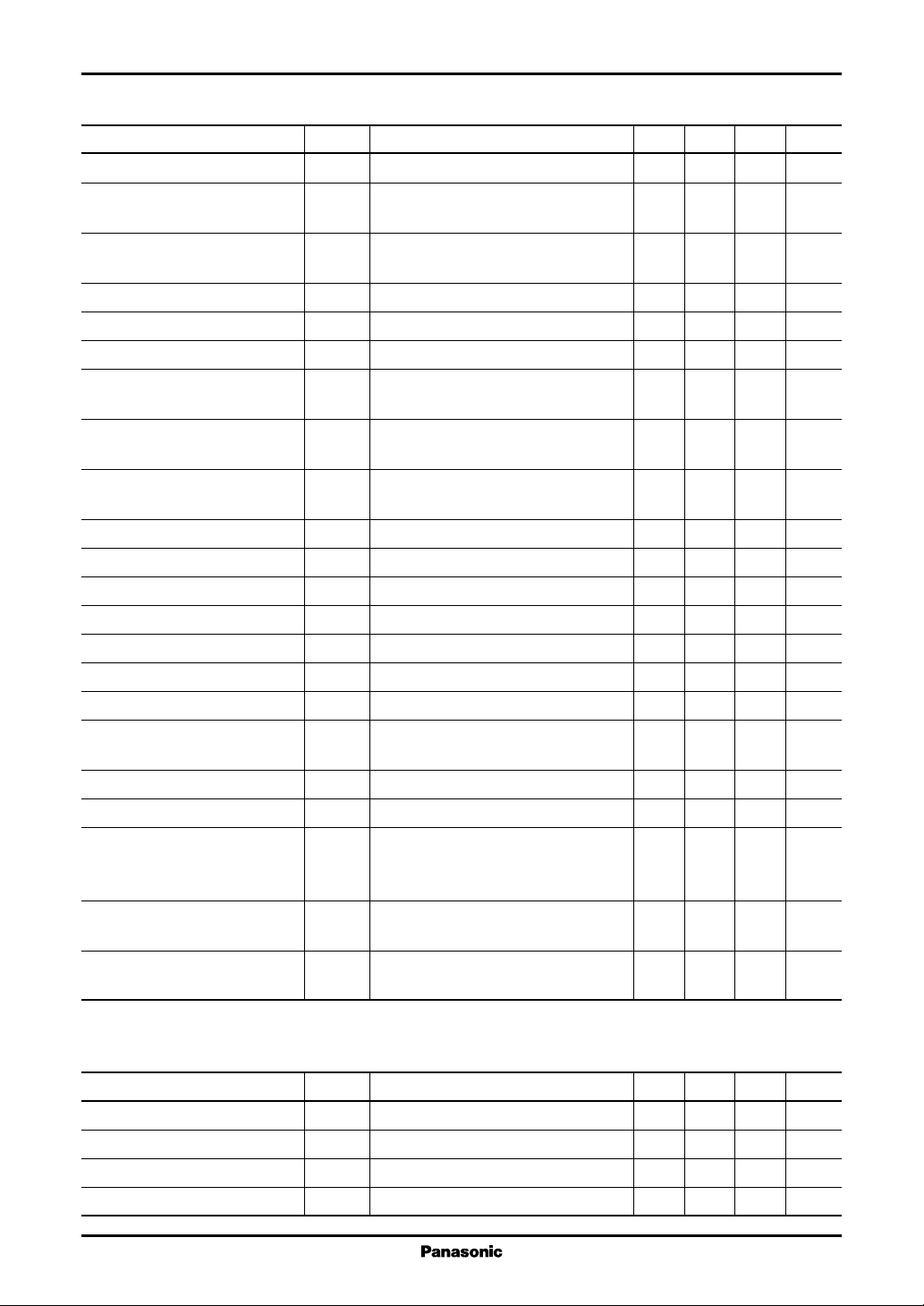
■ Electrical Characteristics at Ta = 25°C
Parameter Symbol Conditions Min Typ Max Unit
Total circuit current I
IF amp. maximum gain GIF
IF amp. minimum gain GIF
Loop amp. gain G
Video amp. gain G
VCO control sensitivity β f = 402.78 MHz 3 7 39 41 MHz/V
Signal to noise ratio S/N
(C/N = ∞) LPF 4.2 MHz, HPF 10 kHz
Inter-modulation interference IM
ratio (2nd) fS = 5.7272 MHz
Inter-modulation interference IM
ratio (3rd) fS = 5.7272 MHz
AFC dead-band width BW
AFC output maximum voltage V
AFC output minimum voltage V
AGC output maximum voltage 1 V
AGC output minimum voltage 1 V
AGC output maximum voltage 2 V
AGC output minimum voltage 2 V
AGC1HVCC
AGC1L
AGC2HVCC
AGC2L
AGC SW level Pin
Key pulse input maximum voltage V
Key pulse input minimum voltage V
Noise amplitude V
Pin 12 voltage V
Pin 15 voltage V
V
TOT
max
min
LA
VA
max
2
3
AFC
AFCHVCC
AFCLV2
= 5 V 28 34 40 mA
CC
PIFIN = −60 dBm, f = 402.78 MHz 22 25 28 dB
V
= 5 V
17
PIFIN = 0 dBm, f = 402.78 MHz −29 −25 dB
V
= 0 V
17
PLA in = −30 dBm, f = 1 MHz 22 24 26 dB
PVA in = −10 dBm, f = 1 MHz 6.5 7.0 7.5 dB
PIFIN = −30 dBm, 100%W, weighting 62 67 dB
PIFIN = −30 dBm, fC = 3.58 MHz 40 6 0 dB
PIFIN = −30 dBm, fC = 3.58 MHz 40 6 0 dB
Pin 2: Low, Pin 3: High 310 360 420 kHz
− V3 value, f = 402.78 MHz 00.5V
value, f = 402.78 MHz 0.1 0.5 V
− V17 value, PIFIN = −70 dBm 00.2V
PIFIN = +10 dBm 0.3 0.5 V
− V16 value, PIFIN = −70 dBm 00.2V
PIFIN = +10 dBm 0.3 0.5 V
f = 402.78 MHz, PIFM = −50 dBm −39 −35 −31 dBm
SW
Input level at V
DC measurement 0.35 V
KEYH
DC measurement 0.1 V
KEYL
f = 402.78 MHz with no modulation 4 10 mV[p-p]
N
= 2.5 V
16
and with de-emphasis
Measure it at Video out pin.
Voltage to get V
12
= 0 V, V2 ≤ 1 V, 1.0 1.35 1.7 V
17
V3 ≥ 4 V with no PIFIN .
Voltage to be AFC center with no PIFIN , 1.03 1.15 1.27 V
15
V
= 0 V, f
17
= 402.78 MHz
VCO
• Design reference data
Note) The characteristics listed below are theoretical values based on the IC design and are not guaranteed.
Parameter Symbol Conditions Min Typ Max Unit
IF amp. frequency characteristic f
IF amp. NF NF
Loop amp. frequency characteristic f
Loop amp. phase PH
3 dB down frequency 600 700 MHz
CIF
f = 402.78 MHz, V
IF
3 dB down frequency 200 250 MHz
CLA
f = 1 MHz to 20 MHz ±5 ±10 °
LA
= 5 V 12 15 dB
17
3
 Loading...