

Panasonic AN6657 Datasheet
AN6657, AN6657S
Micromotor Forward/Reverse Electronic Governors
21.7±0.3
1.2±0.25
0.5±0.1
6.3±0.25
7.62±0.25
3 ~ 15˚
0.3
+0.1
– 0.05
3.8±0.25 (3.45)
0.51min
1
2
3
4
5
6
7
8
16
15
14
13
12
11
10
9
2.54
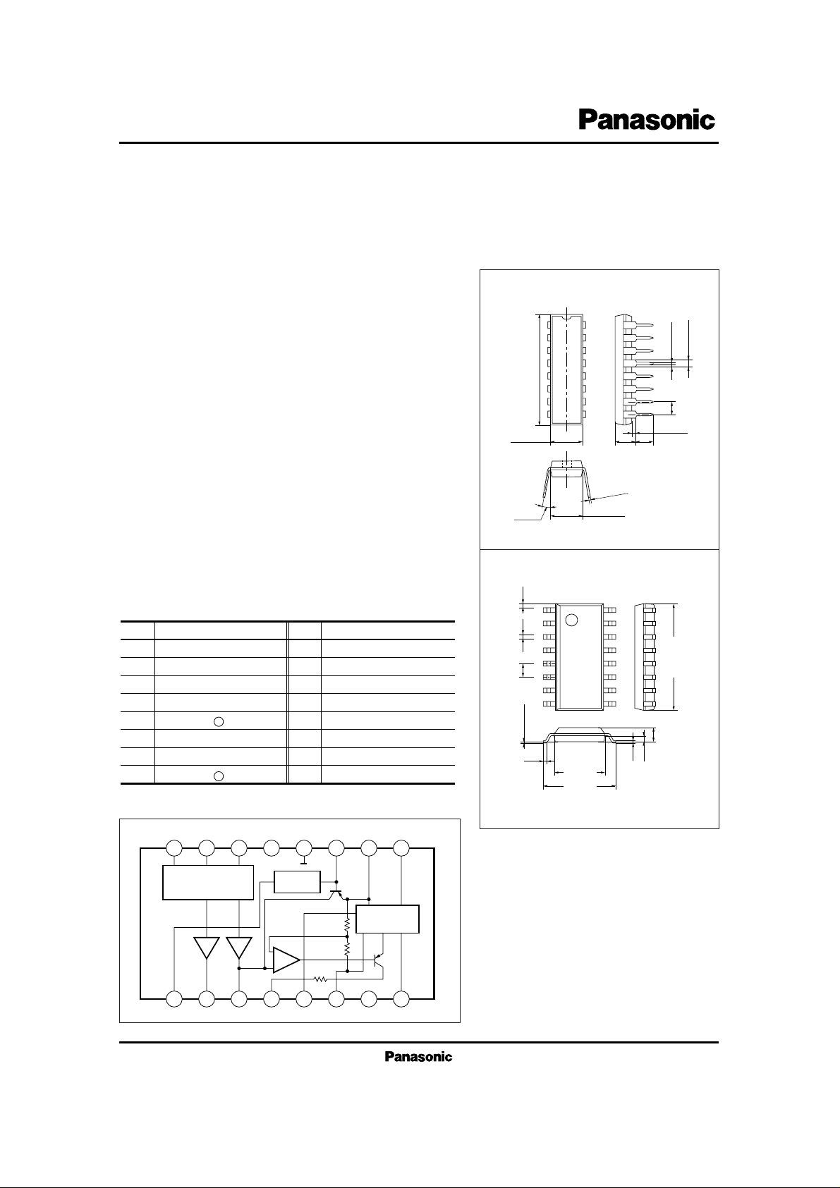
Unit : mmAN6657
16-pin DIL Plastic Package (DIP016-P-0300F)
■ Pin Name
Pin No.
Pin name
1
2
3
4
5
6
7
8
Constant speed setting
Speed control
Speed control
Phase compensation
Motor drive +
Collector connection
Base connection
Motor drive –
9
10
11
12
13
14
15
16
Load characteristic setting
V
CC
To the pin 9
GND pin
NC
Start/Stop
Forward/reverse
Constant speed/FF
Pin No.
Pin name
0.4
0.4±0.251.27
10.1±0.3
Unit : mmAN6657S
0.1±0.1
0.3
16-pin PANAFLAT Plastic Package (SOP016-P-0225A)
1.5±0.2
0.15
0.65
1
2
3
4
5
6
7
8
16
15
14
13
12
11
10
9
6.5±0.3
4.2±0.3
■ Block Diagram
■ Overview
The AN6657 and the AN6657S are electronic governor ICs
capable of controlling the forward/reverse speed, fast forward,
rewind, and start/stop of the micromotors used for the
radio/cassette tape recorders, automatic answering telephone
sets, and so on.
■ Features
•
Operating supply voltage range : VCC=4.5V to 14V
•
Stable reference voltage (1.3V) and easy speed control
•
Large starting torque and maximum control touque Good
secular drift because of external power transistor
•
Provided with the motor stop function : ICC=20µA or less at
stop time
•
Capable of controlling forward/reverse rotation, fast for-
ward/constant speed, and start/stop via 3 input pins
■ Applications
Speed control of the micromotors for the radio cassettes
Speed control of the micromotors for the microcassettes of
the automatic answering telephone sets
Control of the tape loading motors for the DATs, etc.
16115214313412
GND
Drive Mode
Select Logic
Ref.Voltage
Amp.
1kΩ
10kΩ
5
V
CC
1161079
Forward/Reverse
Drive Circuit
8
V
CC
I
CC
I
O
P
D
T
opr
T
stg
V
mA
mA
mW
˚C
˚C
■ Absolute Maximum Ratings (Ta=25˚C)
14.4
50
700
500
380
–20 to +70
–55 to +150
–55 to +125
Supply voltage
Supply current
Output current
Power dissipation
Operating ambient temperature
Storage
temperature
AN6657
AN6657S
AN6657
AN6657S
Parameter Symbol Rating Unit
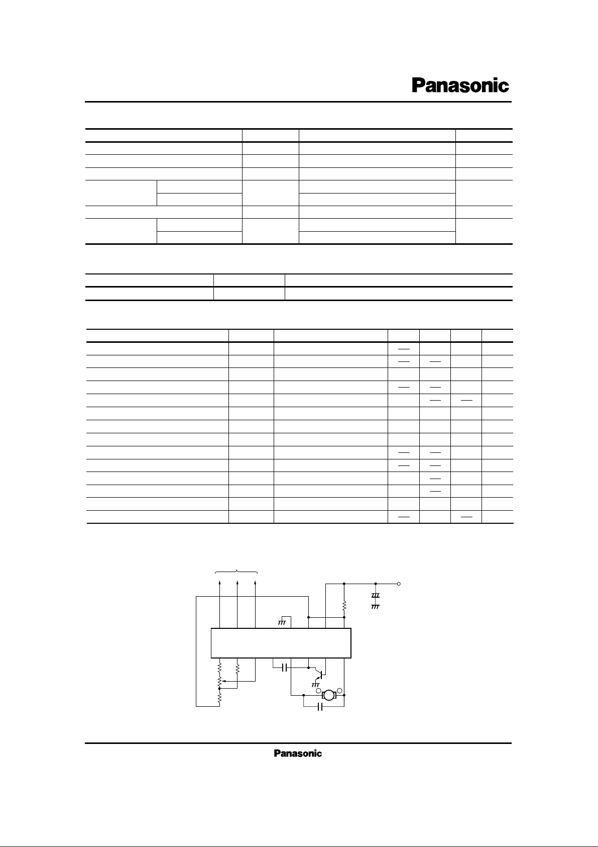
AN6657, AN6657S
1 2 3 4 5 6 7 8
16 15 14 13 12 11 10 9
V
CC
–
+
–
M
+
4.7µF
0.022µF
0.01µF
2SD2249
or
2SD2177
To Mechanism Controller, etc.
NC
1.2Ω
4.3kΩ
15kΩ
1kB
680Ω
3900
rpm/˚C
2000
rpm/˚C
HKN-3A6LDI (Ra=13Ω)
(Matsushita Micromotors Co. Ltd.)
■ Application Circuit
■ Electrical Characteristics (Ta=25˚C)
Bias current
I
bias
10 mA4
V
CC
=5V
Prestart current
I
stop
µA
V
CC
=5V
Reference voltage
V
ref
V
V
CC
=5V
Start voltage
V
CC (s)
V
Supply voltage at which a 50mA current flows to Ra
Start current
I
st
mA
V
CC
=4.5V, Ra=13Ω
%
VCC=
5V, IL=
55mA, N=2000rpm
Rated load r.p.m.
N
L
%0
VCC=
5V, IL=
55mA, N=2000rpm
Forward/reverse r.p.m. difference
∆N
Logi
times
V
CC
=5V
, IL=
55mA, N=4000rpm
FF/rated r.p.m. ratio
∆N
rpm/V
R.p.m. characteristics on voltage change
∆N
V
V
V
CC
=4.5V to 9V, IL=55mA
Select mode input H
V
H
VCC=5V to 14V
6
2.15
1.5
50
3
20
10
5
1.85
3
V
Select mode input L
V
L
VCC=5V to 14V
0.70
%/˚C0.015
Ref. voltage temperature characteristic
∆Vr/Ta
V
CC
=5V, Ta=0˚C to 60˚C
1.1
130
–10
–5
0
1.3
V0.62
Current limiting starting voltage
V
Lim
VCC=9V, RT=1.3Ω
0.70.55
rpm
R.p.m. characteristics on load change
∆N
L
VCC=4.5V, IL=55mA to 90mA
120
2
Parameter Symbol Condition min typ max Unit
■ Recommended Operating Range (Ta=25˚C)
V
CC
Operating supply voltage range
Parameter Symbol Range
4.5V to 14V
 Loading...