

Panasonic AN6545SP, AN6545 Datasheet
AN6545, AN6545SP
Low Power Loss Voltage Regulators
■ Overview
The AN6545 and AN6545SP are the voltage regulators
with strobe pin which can turn on/off an output.
A rated load current is 150mA and an output voltage is
fixed at 5V.
■ Features
• 150mA rated load current and 5V fixed output voltage
• Capable of turning off an output by setting the strobe
pin to the “L” level
• Minimum input/output voltage difference:typ. 0.25V
• Built-in overcurrent protective circuit
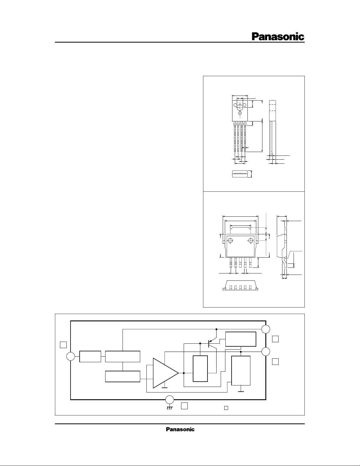
• TO-126 (4-lead) package for the AN6545, and surface mount type 5-pin SIL plastic package for the AN6545SP
+0.5
8.0
– 0.1
3.05
3.8
11.5max.
1.94
15.0min.
0.5
±0.2
1234
1.778
4-pin SIL Plastic Package (SSIP004-P-0000B)
9.5±0.4
1.778
5.334
1234
3.5max.
8.5±0.4 2.3±0.3
7.5±0.3
±0.25
5.0
0.7±0.1
1.5±0.251.5±0.25
0.5±0.1
1.44
1.761.778
5.5±0.3
Unit:mmAN6545
Unit:mmAN6545SP
0.5±0.1
0 — 0.2
■ Block Diagram
1
4
Starter Current Source
Voltage Reference
+
–
GND
(1.1)
1.2±0.25
+0.1
– 0.05
0.5
(2.5)
1.27 0.5±0.1
12345
5-pin SIL Plastic Package (HSIP005-P-0000)
V
1
I
Over Current
Detector
5
2
3
Saturation
Detector
Voltage
Fluctuation
Detector
3
Fin
The numbers in are the pin numbers of the AN6545SP
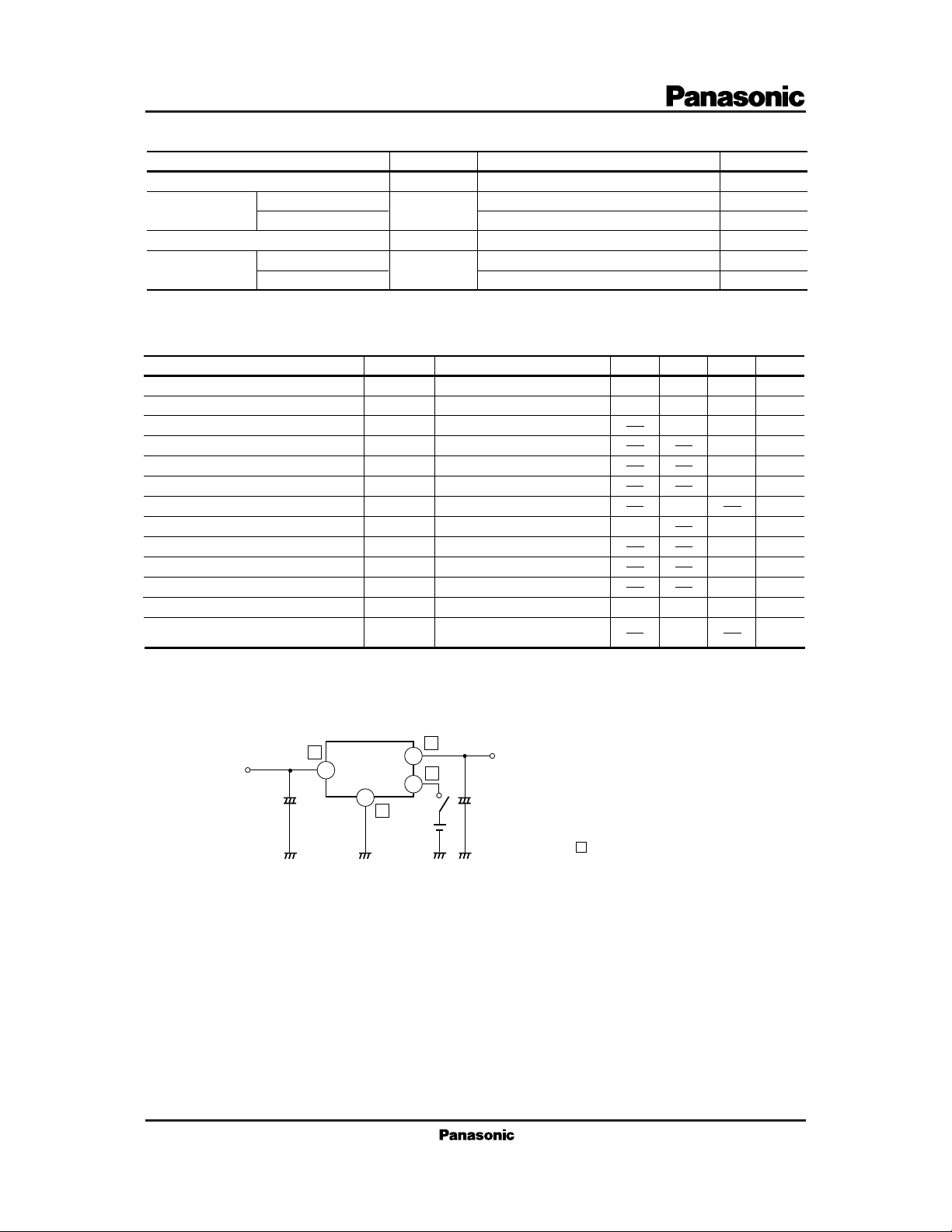
■ Absolute Maximum Ratings (Ta=25˚C)
Parameter Symbol Rating Unit
Supply voltage
Power dissipation
AN6545
AN6545SP
Operating ambient temperature
Storage temperature
*
Mounted onto the PCB
AN6545
AN6545SP
■ Electrical Characteristics (Ta=25˚C)
Parameter Symbol Condition min typ max
REG
REG
V
DIF (min)
I
O (short)
∆I
V
V
V
I
bias
I
rush
biasl
I
OFF
I
S
S (TH)
RR
O
t
L
IN
Output voltage
Output voltage range
Bias current
Load regulation
Line regulation
Minimum input/output voltage difference
Rush current
Output short-circuit current
Load bias current change
Off-state cathode current
Strobe pin input current
Strobe pin threshold voltage
Ripple rejection ratio
V
I
P
D
T
opr
T
stg
=12V, IO=150mA
V
I
=6 to 14.4V, IO=0 to 150mA
V
I
=12V, IO=0mA
V
I
=12V, IO=0 to 150mA
V
I
=6 to 14V, IO=150mA
V
I
=4.5V, IO=150mA
V
I
=4.5V, IO=0mA
V
I
=12V
V
I
=12V, IO=0 to 150mA
V
I
=12V, VS=0V
V
I
VI=12V, VS=2.5V
=12V
V
I
=10 to 14V, IO=150mA,
V
I
f=120kHz
14.4
*
1300
500
–20 to+75
–55 to+150
–55 to+125
4.8
4.7
350
0.8
5.2 V5
5.3
100
100
550
200
2.4
V
mW
mW
˚C
˚C
˚C
Unit
V5
4mA2.9
mV
mV
V
5
mA2.5
mA
mA
10
µA
2
µA
V2
dB55
■ Applica tion Circuit
5
AN6545
10µF
1
AN6545SP
3
F
In
When using at a low temperature, it is recommended to use capacitors with low internal impedance (for example, tantalum
·
capacitors) for output capacitors.
2
4
STB
3
Out
1
10µF
The number in are the pin numbers of the AN6545SP
 Loading...