

■ Overview
The AN6480 is an integrated circuit designed for IF amplifier
for car telephone and wireless installation.
■ Features
•
Excellent output voltage linearity for level detector
•
Low temperature coefficiency of output voltage for level
detector
•
Voltage stabilizer built-in
AN6480
IF Amplifier for Car Telephone
1
2
3
4
5
6
7
8
9
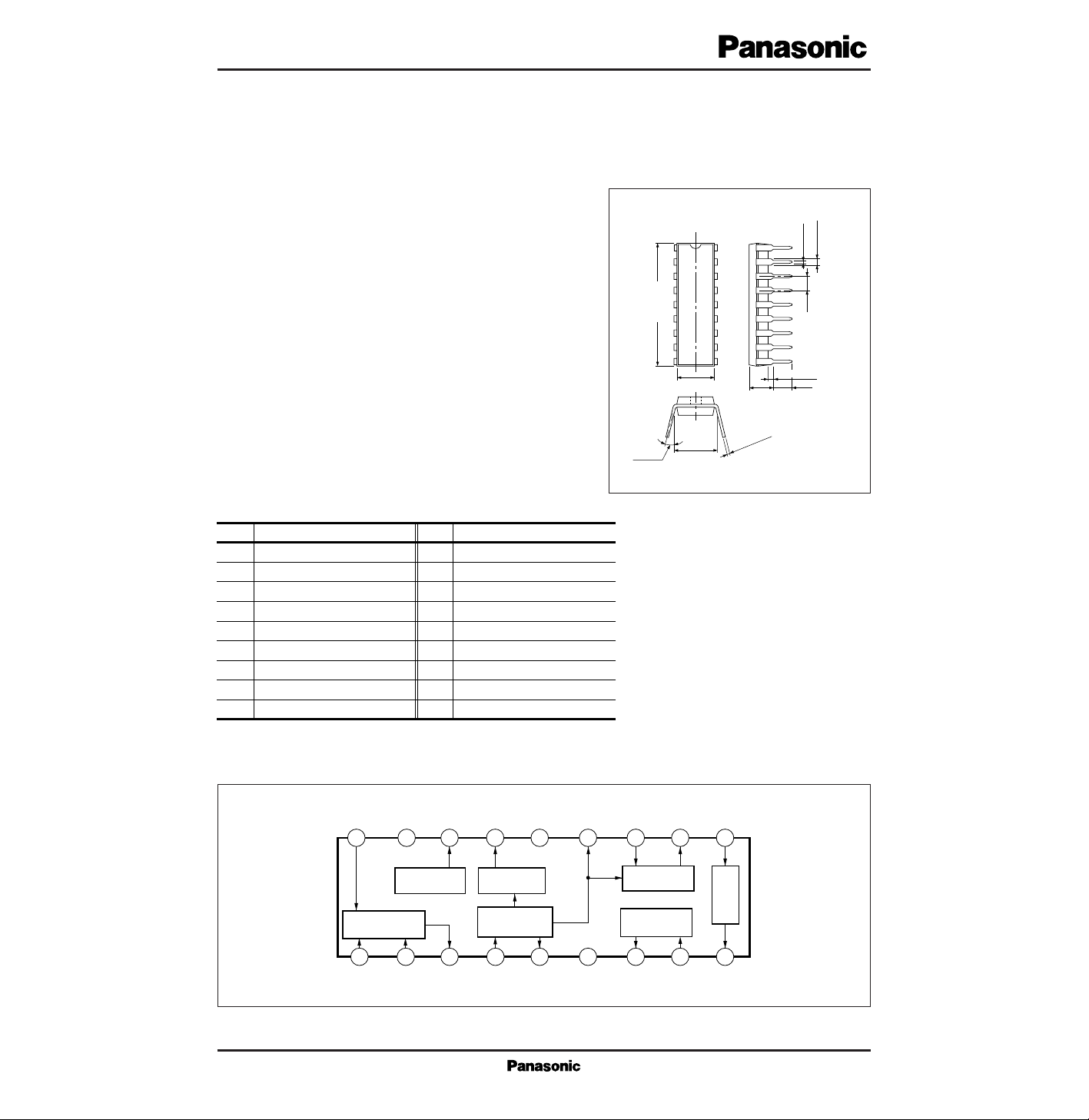
21.7±0.3
1.2±0.25
3 to 15˚
Unit : mm
6.3
±
0.25
0.5±0.1
2.54
(3.45)
7.62±
0.25
18-pin DIL Plastic Package (DIP018-P-0300D)
0.3
+0.1
– 0.25
18
17
16
15
14
13
12
11
10
0.51min.
3.8±0.25
■ Block Diagram
■ Pin Descriptions
Pin No.
Pin name
1
2
3
4
5
6
7
8
9
Oscillator input
Second mixer input
Second mixer output
IF amp. input
Reference input
GND
Squelch output
Squelch input
O.P amp. output
Pin No.
Pin name
10
11
12
13
14
15
16
17
18
OP. amp. input
FM detector output
FM detector input
IF amp. output
V
CC
Level detector output
Voltage regulator output
GND
Oscillator input
Osc. Input GND V
18 17 16 15 14
Output
2nd Mixer
Reg.
1
Osc.
Input
2
2nd Mix.
Input
3
2nd Mix.
Output
Level Det.
Output
Level Det.Regulator
IF Amp.
4
IF Amp.
Input
CC
5
Ref.
IF Amp.
FM Det.
Output
13 12 11
678
Input
FM Det.
Output
FM Det.
SQ
GND SQ
OutputSQInput
OP. Amp.
Input
10
OP.
Amp.
9
OP. Amp.
Output
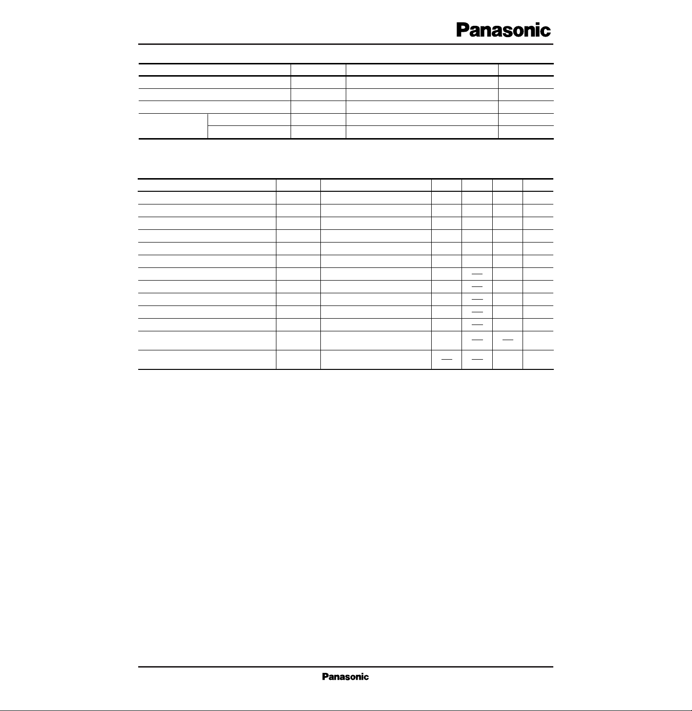
V
CC
I
CC
P
D
T
opr
T
stg
Supply voltage
Supply current
Power dissipation (Ta=75˚C)
Operating ambient temperature
Storage temperature
Temperature
V
mA
mW
˚C
˚C
Parameter Symbol Rating Unit
■ Absolute Maximum Ratings (Ta=25˚C)
8.5
15
130
–30 to + 85
–55 to +125
Parameter Symbol Condition min typ max
■ Electrical Characteristics (Ta=25˚C)
Current consumption (no-signal)
5I
CC
12.5 mA9
IF amp. bias
5.8V
4–17
6.4 V6.1
IF amp. bias
5.8V
5–17
6.4 V6.1
Regulator output voltage
3.8V
16–17
4.4 V
OP. amp. input voltage
1.7V
10–17
2.3 V2.0
OP. amp. output voltage
1.7V
9–17
2.3 V2.0
Level detector balance
–20I
15
25 µA
4.1
SQ output “L” voltage
– 0.05V
7–17
0.2 V
SQ output “H” voltage
4.7V
7–17
5.1 V
Level detector voltage (no-signal)
2.9V
15–17
4.3 V
SW
1
…
OFF, SW
2
…
OFF
Level detector min. output voltage
1.3V
15–17
2.25 V
SW
1
…
OFF, SW
2
…
ON
FM detector output voltage
–8.5V
no (FM Det.)
dBs
SW
1
…
ON, SW
2
…
ON
±3kHz modulation
FM detector residual noise
V
0 (FM Det.)
–58 dBs
SW
1
…
ON, SW
2
…
ON
Non-modulation
Unit
 Loading...