

Panasonic AN6425K Datasheet
■ Overview
The AN6425K is a high-function speech network IC with
speaker amplifier. It incorporates a transmitter-system non-linear circuit, receiver digital VRs, etc. and is suitable for realizing the multifunctional telephone sets.
■ Features
•
Speech network IC for the multifunctional telephone sets
•
Capable of interfacing with the light-weight small receivers
and ECM transmitters
•
Built-in 2V REG constant voltage source (2V typ) for ECM
•
Built-in non-linear circuits in the transmitter and receiver
systems in order to eliminate ambient noises
•
Built-in speaker amplifier and capable of driving with a main
wire current
•
Built-in hold-tone amplifier, key-in-tone amplifier, and
DTMF transmitter, and capable of setting the mode with the
control pins
•
Automatic gain control (automatic pad function) according to
a circuit curret
•
Built-in tertiary active filter circuit and capable of sending a
DTMF circuit with much higher harmonic at a low distortion
factor
•
Built-in single touch receiver volume-up function (about
6dB)
AN6425K
Speech Network Circuit
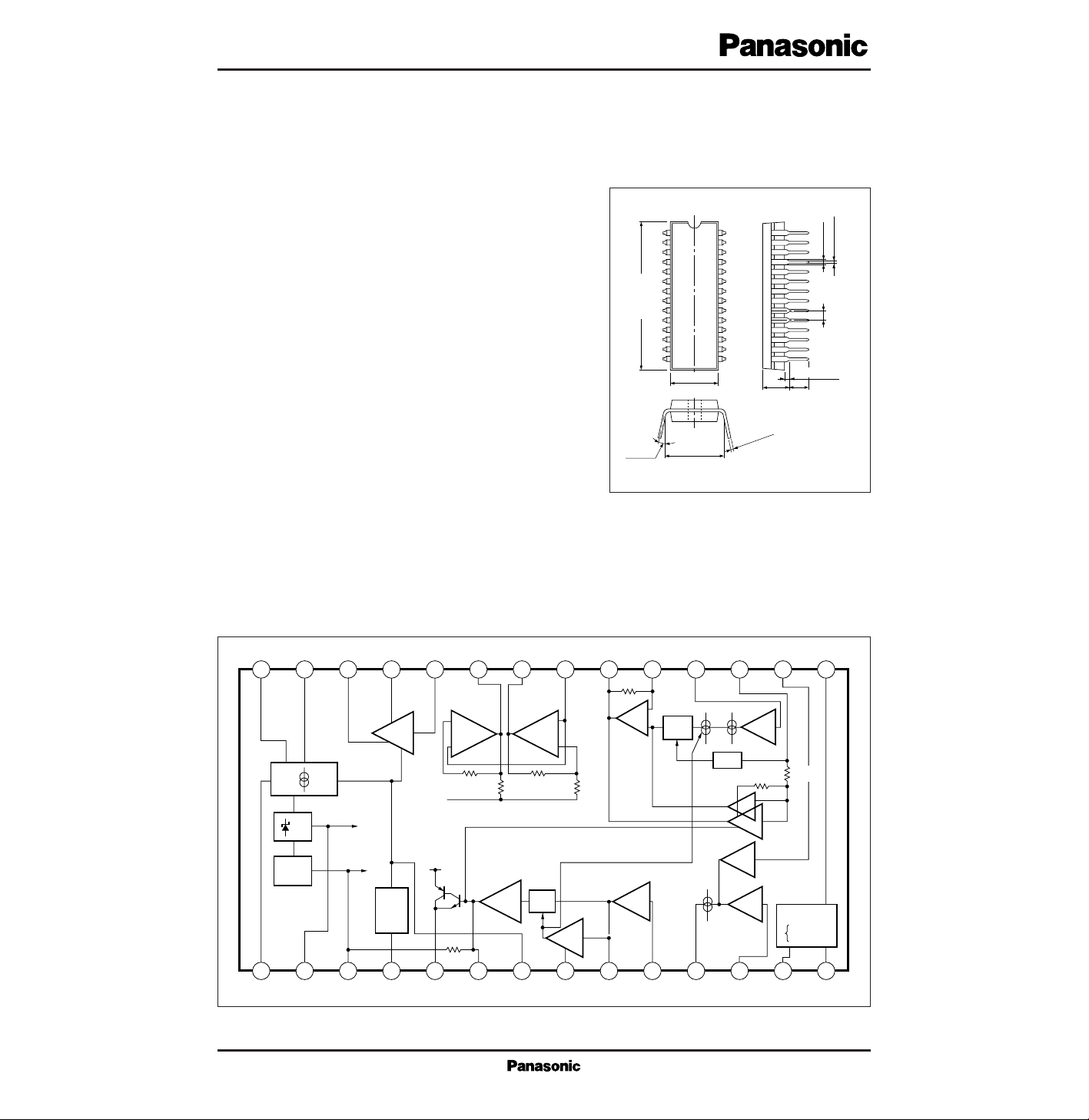
Unit : mm
1
2
3
4
5
6
7
8
9
10
11
12
13
14
28
27
26
25
24
23
22
21
20
19
18
17
16
15
26.7±0.3
0.5±0.1
3 to 15˚
8.4
±0.3
0.9±0.25
1.778
4.8±0.25
28-pin Shrunk DIL Plastic Package (SDIP028-P-0400B)
3.05±0.25
10.16±0.25
0.3
+0.1
– 0.05
1.05±0.25
■ Block Diagram
VL
28 27 26 25 24 23 22 21 20 19 18 17 16 15
CLASS B
BTL
SP
Amp.
CLASS A
Push pull
2V REG
2V
1V
1 2 3 4 5 6 7 8 9 10 11 12 13 14
1V REFF
Battery
Selector
+
REC
DRIVER
–
30kΩ
1V
VL
SEND
Amp
65kΩ
REC
DRIVER
30kΩ
D12
dB
+
–
MUTE
GND
80kΩ
–
+
2kΩ2kΩ
Filter
Amp.
D6dB
D5dB
D3dB
DVR
D3dB
KT
TT
HT
in
MIC
REC
40kΩ
in
in
4kΩ
Logic
INV
NAND
V
L
I
L
P
D
T
opr
T
stg
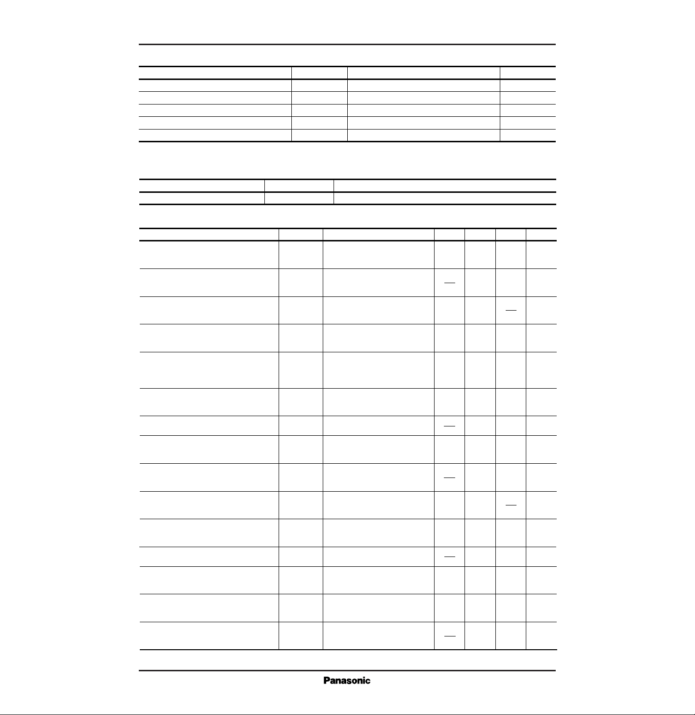
Supply voltage
Supply current
Power dissipation
Operating ambient temperature
Storage temperature
V
mA
mW
˚C
˚C
Parameter Symbol Rating Unit
■ Absolute Maximum Ratings (Ta=25˚C)
14.4
*
120
*
1200
*
–20 to + 65
–55 to +150
*
VCC × ICC <1200mW
Parameter Symbol Range
■ Recommended Operating Range (Ta=25˚C)
Operating supply voltage range
V
L
3 to 12V
Parameter Symbol Condition min typ max
■ Electrical Characteristics (Ta=25˚C)
G
V
(REC)
Open between the Pins19 and 20. Measure the
output between the Pins22 and 23 when a signal (–55dBm) is input to the Pin18.
Receiver distortion factor
THD
(REC)
%1
Open between the Pins19 and 20. Measure the output distortion factor between the Pins 22 and 23
when a signal
(–55dBm) is input to the Pin18.
Receiver maximum output voltage
V
O
(REC)
dBm+3
D Automatic pad
AP
(REC)
dB
Input a signal (–45dBm) to the Pin18 and measure an output change between the Pins22 and
23 when I
L
changes from 80mA to 30mA.
MUTE
(REC)
Input a signal
(–45dBm)
to the Pin18 and
measure an output change between the Pins
22 and 23 when the Pin12 changes from no
microphone input signal to –40dBm.
dB
Input a signal
(–45dBm)
to the Pin18 and
measure an output change between the Pins
22 and 23 when the Pin12 is set from H to L.
Receiver D digital VR
DVR
dBm–50
Measure the output between the Pins22 and
23 when there is no signal at the Pin18.
–3
Receiver noise output
V
no
(REC)
dB42.5
Open bitween the Pins3 and 6. Measure
the output between the Pins28 and 1 when
a signal (–45dBm) is input to the Pin12.
Transmitter gain
G
V
(SEND)
%
Transmitter distortion factor
THD
(SEND)
dBm5
Open between the Pins3 and 6. Measure the
output distortion factor between the Pins28 and 1
when a signal
(–45dBm) is input to the Pin12.
Transmitter maximum transmission level
V
O
(SEND)
dB–3 –1.5
–60
29.5
45
5
–1.5
5
8
–45
–6
2
40
Receiver gain
53 dB50.548
0
–6
D Receiver noise prevention
dB–5 –3–7
4
Transmitter D automatic pad
AP
(SEND)
Input a signal (–35dBm) to the Pin12 and
measure an output change between the Pins
28 and 1 when I
L
changes from 80mA.
dBm–65
Measure the output between the Pins28 and
1 when there is no signal at the Pin18.
Transmitter noise prevention
V
no
(SEND)
dB26.5
HOLD TONE gain
G
V
(HOLD)
dB41.5
Ground the Pin24. Input a signal
(–30dBm)
to the Pin17 and measure the
output change between the Pins 28 and 1.
TOUCH TONE gain
G
V
(TOUCH)
%1
Ground a signal (–45dBm) to
the Pin16 and measure the output between the Pins28 and 1.
3
44
6
1.5
39
23.5
TOUCH TONE distortion factor
THD
(TOUCH)
Ground the Pin14. Input a signal (–45dBm)
to the Pin16 and measure the output distortion factor between the Pins 28 and 1.
Unit
Input a signal to the Pin18 and measure
the output between the Pins22 and 23 at
an output distortion factor of 5%.
Input a signal to the Pin12 and measure
the output between the Pins28 and 1 at
an output distortion factor of 5%.
*
IL=30mA and Freq=1kHz unless otherwise specified.
Parameter Symbol Condition min typ max
■ Electrical Characteristics (cont.) (Ta=25˚C)
dB–3 –1.5–6
TOUCH TONE D automatic pad
AP
(TOUCH)
Ground the Pin14. Input a signal (–45
dBm) to the Pin16 and measure an output change between the Pins 28 and 1
when I
L
changes from 80mA to 30mA.
dB5045
SP amplifier gain
G
V
(SP)
Ground the Pin15. Input a signal
(–50dBm) to the Pin24 and measure
the output between the Pins 25 and 26.
%10
SP distortion factor
THD
(SP)
Ground the Pin15. Input a signal
(–50dBm)
to the Pin24 and measure the output distortion factor between the Pins 25 and 26.
Unit
*
I
L
=30mA and Freq=1kHz unless otherwise specified.
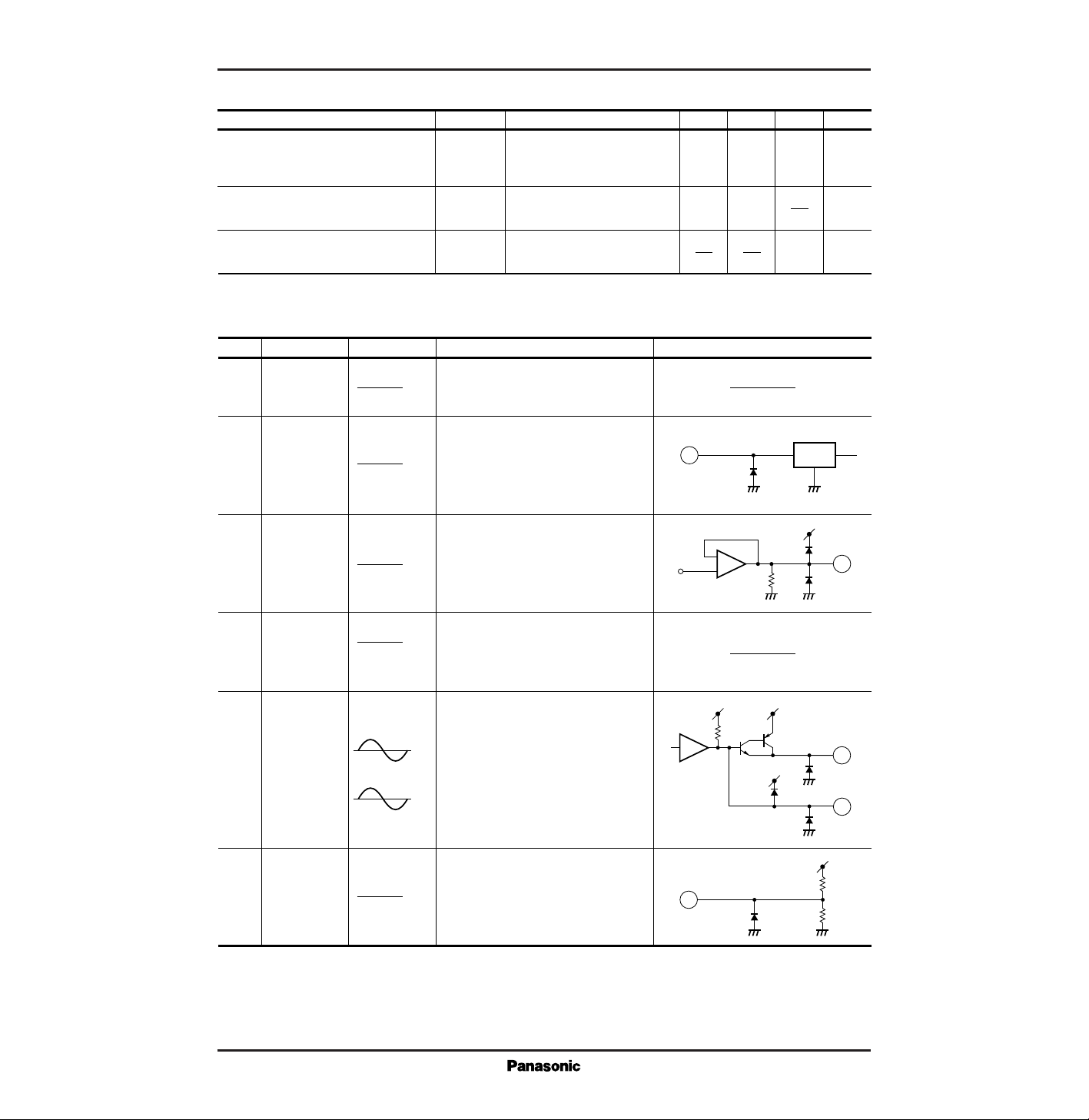
■ Pin Descriptions
1
2
3
4
5
6
7
GND
2V REG
1V REF
BT
1/2V
L
Ground pin.
Connect to the output of the diode
bridge.
2V internal stabillized power supply
output pin.
Connect to GND via 220µF. The current
obtainable from this pin is 5mA or less
(at I
L
=20mA).
1V reference coltage output pin.
Connect to GND via 47µF. No current
is allowed to be input/output from this
pin.
External battery connection pin.
Connect the 3 to 6V battery to GND.
Connect to GND directly when the BT
function is not used.
Transmitter output.
Transmitter gain control pin.
Controls the gain and frequency characteristic of the transmitter system with
external C and R.
Automatic pad control pin.
Capable of controlling the pad operating
point with the external resistor.
Typical waveform
Description Equivalent circuitPin No. Pin name
SEND
OUTPUT
SEND
DRIVER
DC 0V
DC 2V
DC 1V
DC
0.3V
DC
0 to 6V
(Supplied from
Outside)
5/7 × V
L
V
ref
2V
REG
2
3
+
–
V
CC
10kΩ
1V
5
V
CC
V
L
Vref
65.3kΩ
6
V
L
20kΩ
47kΩ
7
 Loading...