

Panasonic AN6152 Datasheet
■ Overview
The AN6152 is an integrated circuit designed for telephone
speech network. It has the basic function which is necessary to
apply a sound signal onto the line and excellent in branch performance.
■ Features
•
Wide operating voltage range : 3 to 11.5V
•
Built-in amplifiers for “Dial Tone” and “DTMF”
•
Amplifier
•
Each amplifier gain automaticaly changeable depending on
line current.
•
Various types of microphone and receiver are available.
AN6152
Speech Network Circuit
1
2
3
4
5
6
7
8
16
15
14
13
12
11
10
9
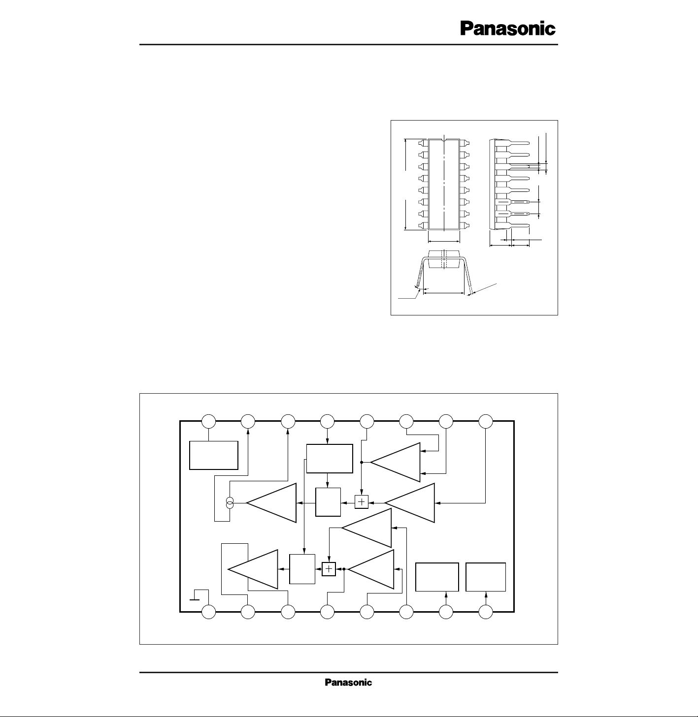
19.2±0.3
1.22±0.25
3 to 15˚
Unit : mm
6.2±0.3
0.5±0.12.54
5.2±0.25 3.05±0.25
7.62±0.25
0.3
+0.1
– 0.05
1.1±0.25
16-pin DIP Package (DIP016-P-0300D)
■ Block Diagram
V
CC
V
L
16 15
Current
Source
1
GND
REC
Main Amp.
2 3 4 5 6 7 8
RO1 RO2 RF RI KT DM Vr
ST AP NF MI2 MI1 DT
14 13 12 11 10 9
SEND
Main Amp.
ATT
Control
ATT
ATT
KT
Pre Amp.
REC
Pre Amp.
MIC
Pre Amp.
DTMF
Pre Amp.
Logic
V
REF
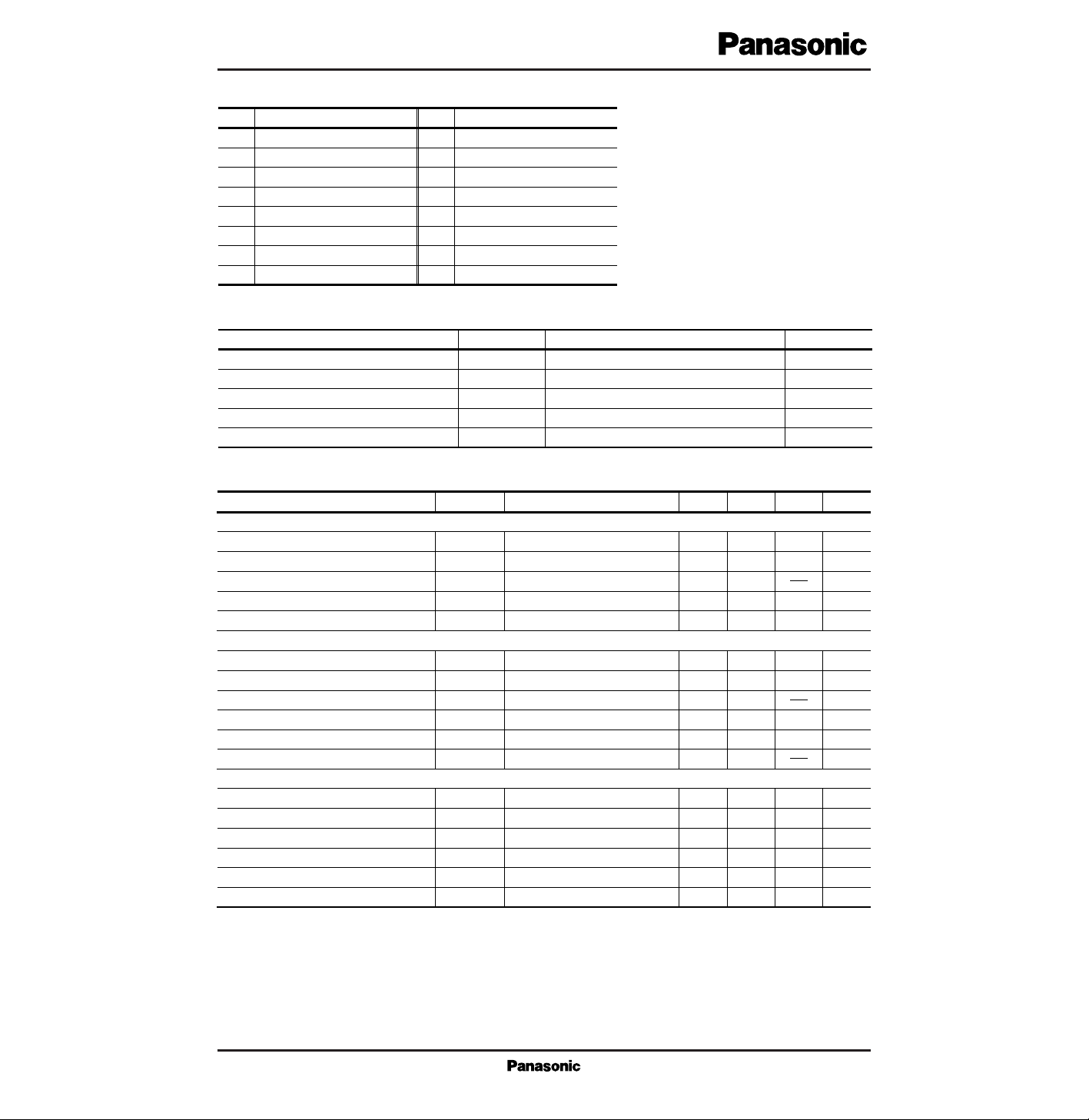
■ Pin Descriptions
Pin No.
Pin name
1
2
3
4
5
6
7
8
GND
REC output
REC output
REC filter
REC input
KEY IN TONE input
DIAL mute SW
V reference
Pin No.
Pin name
9
10
11
12
13
14
15
16
DTMF input
MIC input
MIC input
SEND NF
ATT control
SIDE tone
LINE
Internal suppuly voltage
V
L
I
L
P
D
T
opr
T
stg
Line voltage
Line current
Power dissipation (Ta=60˚C)
Operating ambient temperatuer
Storage temperature
V
mA
mW
˚C
˚C
Parameter Symbol Rating Unit
■ Absolute Maximum Ratings (Ta=25˚C)
14.4
120
1380
–30 to + 75
–55 to + 150
Parameter Symbol Condition min typ max Unit
■ Electrical Characteristics (Ta=25˚C)
Receiver System
Receiver gain (1)
Max. receiver
G
V–R1
39.5 dB
I
L
=30mA, Vi=–50dBV
Receiver gain (2)
31.5G
V–R2
dB
I
L
=80mA, Vi=–50dBV
V
O–R
dBVIL=30mA, THD=5%
34.5
0
34.0
5
37.5
KEY IN TONE gain (1)
G
V–KT1
dBIL=30mA, Vi=–50dBV 28.5 31.0 33.5
KEY IN TONE gain (2)
*
1
G
V–KT2
dBIL=80mA, Vi=–50dBV 25.5 28.0 30.5
36.5
Note) Operating supply voltage range : V
CC (opr)
= 3 to 11.5V
*
1 These values are of reference values but not guaranteed values.
Transmission System
Transmission gain (1)
Max. transmission level
G
V–T1
38 dB
I
L
=30mA, Vi=–50dBV
Transmission gain (2)
29.5G
V–T2
dB
I
L
=80mA, Vi=–50dBV
V
O–T
dBVIL=30mA, THD=5%
33
0
32.0
5
35.5
DTMF gain (1)
G
V–DT1
dBIL=30mA, Vi=–50dBV 28.5 30.5 32.5
DTMF gain (2)
G
V–DT2
dBIL=80mA, Vi=–50dBV 25.0 27.0 29.0
DTMF transmission level
V
O–DT
dBVIL=30mA, THD=5% 0 5
34.5
Power Supply
DC line voltage (1)
Internal supply voltage (1)
V
L–1
3.6 V
I
L
=20mA
DC line voltage (2)
7.5V
L–2
V
I
L
=120mA
V
CC–1
VIL=20mA
2.6
1.8
9.0
2.1
3.1
Internal supply (2)
V
CC–2
VIL=120mA 5.8 6.5 7.2
AC impedance (1)
*
1
Z
AC–1
ΩIL=30mA, fin=1kHz 450 610 750
AC impedance (2)
*
1
Z
AC–2
ΩIL=90mA, fin=1kHz 450 610
10.5
2.4
750
 Loading...