

Panasonic AN5765 Datasheet
ICs for TV
AN5765
CRT heater voltage control IC
■ Overview
The AN5765 is an IC for CRT heater voltage control.
The incorporation of 4 values of heater voltage changeover output circuit, 5 V power supply and reset circuit for
microcomputer, and the adoption of SIP 7-pin package
with fin can realize the rationalization and power saving
of the set.
■ Features
• Incorporating 4 values changeover output circuit
• Incorporating 5 V constant voltage output
• Incorporating reset function
• Incorporating current protection and thermal protection
circuit
■ Applications
• CRT monitors
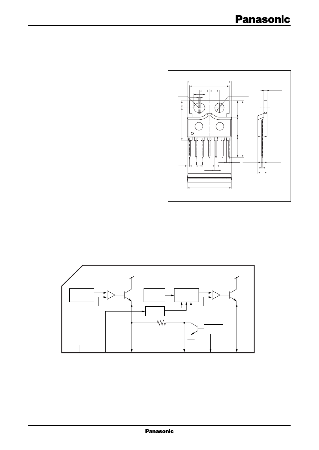
■ Block Diagram
R1.80
2.80±0.10
12.50±0.10
(0.83)
(17.10)
15.30
±0.20
(3.80)
2.54
(3.80)
0.60
±0.10
(1.20)
16.90±0.30
(1.00)
φ3.60±0.10
(6.40)
7.70±0.20
22.00±0.30
(7.80)
7
(0.30)
1.45±0.20 1.80±0.20
(4.20)
0.60
1
Unit: mm
±0.10
1.20
+0.10
0.35
–0.05
3.50±0.30
HSIP007-P-0000
Regulator
voltage
1
CC
V
2
SW input
Thermal
protect
Regulator
voltage
Switch
Reset
3
5 V
4
GND
5
Reset output
6
7
Heater output
1
AN5765 ICs for TV
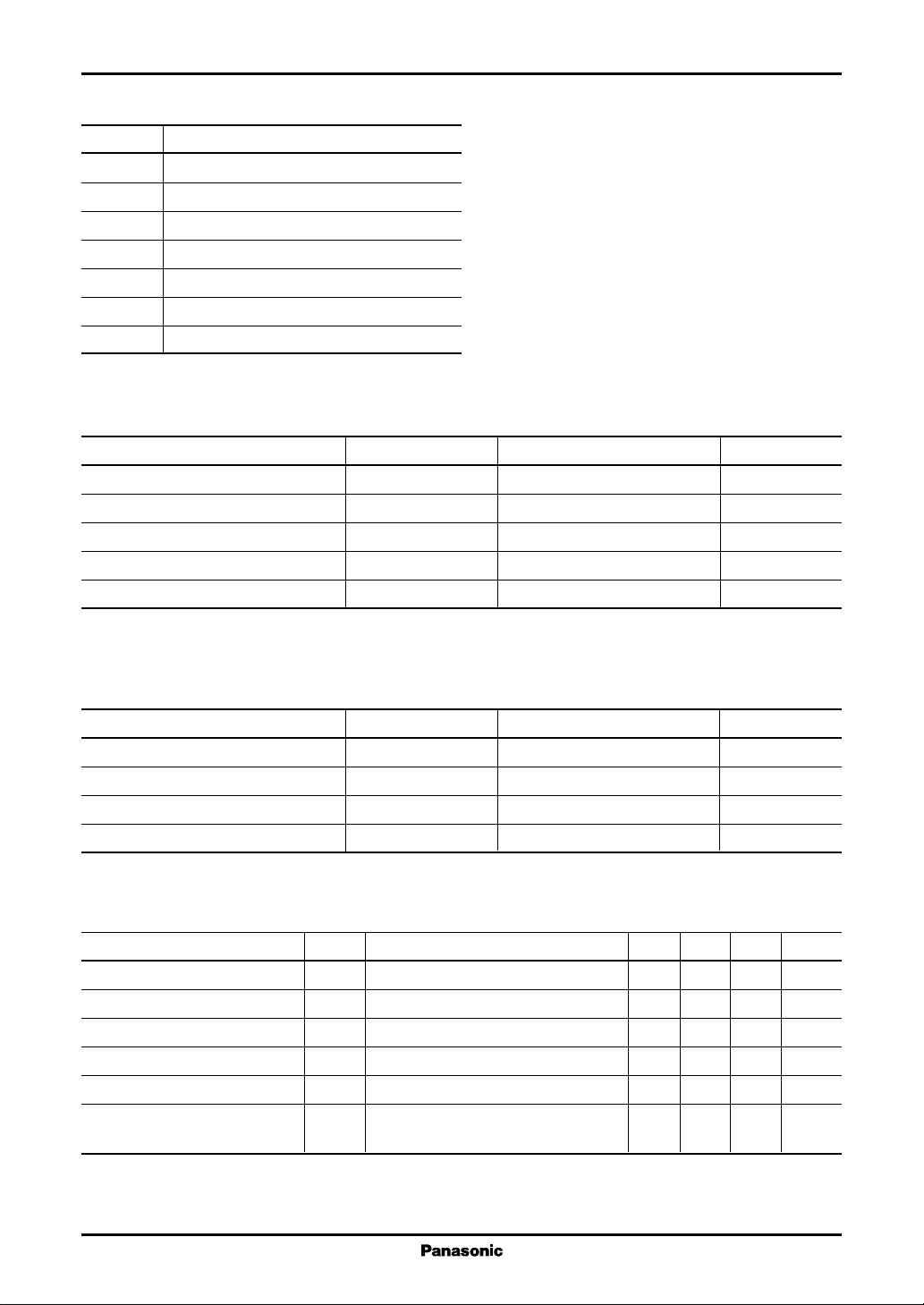
■ Pin Descriptions
Pin No. Description
1V
2 SW input
3 Regulator output (5 V)
4 GND
5 Reset output
6 Capacitor for delay
7 Heater output
Note) Fin has the same potential as GND
■ Absolute Maximum Ratings
Supply voltage V
Supply current I
Power dissipation
Operating ambient temperature
Storage temperature
Note)*1: Except for the operating ambient temperature and storage temperature, all ratings are for Ta = 25°C.
2: The power dissipation shown is for the IC package at Ta = 75°C.
*
CC
Parameter Symbol Rating Unit
CC
CC
2
*
1
*
1
*
P
D
T
opr
T
stg
12.0 V
2 000 mA
1 400 mW
−20 to +75 °C
−55 to +150 °C
■ Recommended Operating Range
Parameter Symbol Range Unit
Supply voltage V
SW input V
Regulator output maximum output current
Heater output maximum output current I
Note) '+' denotes current flowing into the IC, and '−' denotes current flowing out of the IC.
I
3max
7max
CC
2−4
7.5 to 11.0 V
0 to V
−400 to +0.1 mA
−1 000 to +0.05 mA
■ Electrical Characteristics at Ta = 25°C
Parameter Symbol Conditions Min Typ Max Unit
Circuit current pin 1 I
Circuit voltage pin 2 V
Circuit voltage pin 3 V
Circuit voltage pin 5 V
Circuit voltage pin 7 V
Heater output off voltage V
VCC = 8 V, load (R3, R7) open 2 4.5 7 mA
CC
2−4VCC
3−4VCC
5−4VCC
7−4VCC
7−4OFFVCC
= 8 V, R3 = 1 kΩ, R7 = 500 Ω 1.7 2.0 2.3 V
= 8 V, R3 = 1 kΩ, R7 = 500 Ω 4.75 5.0 5.15 V
= 8 V, R3 = 1 kΩ, R7 = 500 Ω 4.75 5.0 5.15 V
= 8 V, R3 = 1 kΩ, R7 = 500 Ω 4.25 4.5 4.75 V
= 8 V, V2 = 0 V, 0 0.1 V
R3 = 1 kΩ, R7 = 500 Ω
3
V
2
ICs for TV AN5765
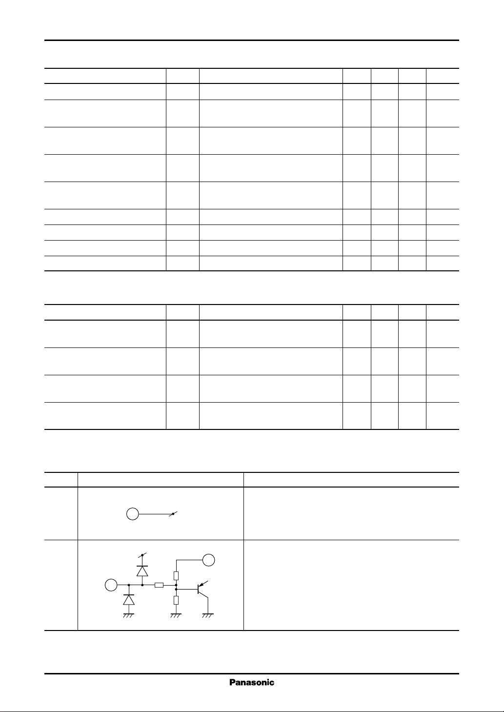
■ Electrical Characteristics at Ta = 25°C (continued)
Parameter Symbol Conditions Min Typ Max Unit
Regulator output voltage V
Heater output voltage high V
Heater output voltage mid. V
Heater output voltage low V
Heater output voltage off V
Delay capacitor discharge current I
Delay capacitor charge current I
Reset output voltage low V
Reset output voltage high V
3RLVCC
7HIVCC
7MIDVCC
7LOVCC
7OFFVCC
6C
6D
5LOVCC
5HIVCC
• Design reference data
Note) The characteristics listed below are theoretical values based on the IC design and are not guaranteed.
Parameter Symbol Conditions Min Typ Max Unit
Heater output operation start V
OP7VCC
supply voltage to 4.5 V.
Delay capacitor charge start V
OP3
regulator voltage becomes low to high.
Delay capacitor discharge start V
OF3
regulator voltage becomes high to low.
Reset output operation stop V
OFF3
regulator voltage becomes high to low.
= 8 V, R3 = 20 Ω, R7 = 10 Ω 4.7 5.0 5.1 V
= 8 V, V2 = 5 V, 6.15 6.40 6.65 V
R3 = 20 Ω, R7 = 10 Ω
= 8 V, V2 = 3 V, 4.95 5.2 5.45 V
R3 = 20 Ω, R7 = 10 Ω
= 8 V, V2 = 2 V, 4.25 4.5 4.75 V
R3 = 20 Ω, R7 = 10 Ω
= 8 V, V2 = 0 V, 0 0.1 V
R3 = 20 Ω, R7 = 10 Ω
VCC = 5.0 V, V6 = 1 V 1 5 mA
VCC = 6.0 V, V6 = 1 V −15 −8.5 −4 µA
= 8 V, V6 = 3.3 V 0 0.15 V
= 8 V, V6 = 4.5 V 4.7 5.0 5.1 V
voltage at which V7 becomes 0 V 6.1 6.35 6.5 V
Regulator voltage at which pin 6 4.4 4.6 4.8 V
Regulator voltage at which pin 6 3.9 4.1 4.3 V
Regulator voltage at which pin 5 3.9 4.1 4.3 V
■ Terminal Equivalent Circuits
Pin No. Equivalent circuit Description
1V
CC
V
CC
3
1
2 SW input:
V
30 kΩ
2
200 Ω
20 kΩ
:
CC
Power supply pin
DC 8 V (typ.) application
SW input pin for changing over heater output (pin 7)
voltage
Changeover from DC 0 V to 5 V
3
 Loading...