

Panasonic AN5764N Datasheet
ICs for TV
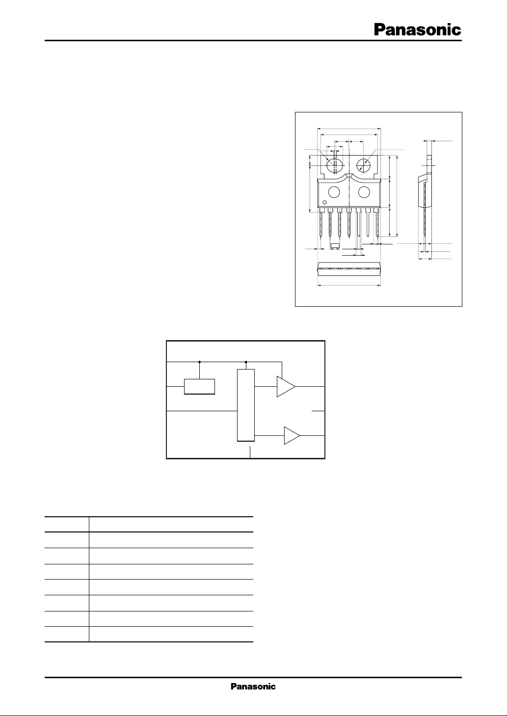
AN5764N
Horizontal picture position control IC for CRT monitor
■ Overview
The AN5764N is an IC for CRT monitor horizontal
picture position control. The picture position can be controlled by DC voltage, and the adoption of fin-attached
SIL 7-pin package contributes to the rationalization of
monitor set.
■ Features
• CRT monitor position control
• Built-in low voltage output circuit
• Built-in DC control circuit
■ Applications
• CRT monitor
■ Block Diagram
1
V
CC
V-REG
R1.80
±0.10
2.80
±0.10
12.50
(0.83)
(6.40)
±0.20
7.70
(7.80)
±0.10
±0.30
22.00
1.45
Unit: mm
±0.20
1.80
0.35
3.50
1.20
±0.20
+0.10
–0.05
±0.30
±0.10
(17.10)
15.30
±0.20
(3.80)
(3.80)
(4.20)
0.60
1
0.60
2.54
±0.10
(1.20)
16.90
±0.30
(1.00)
φ3.60
7
(0.30)
HSIP007-P-0000
72
■ Pin Descriptions
Pin No. Description
1V
2 Constant voltage output (3 V)
3 Control input
4 GND
5 Out1 (Positive output)
6N.C.
7 Out2 (Negative output)
Note) The fin is at the same potential as GND.
CC
Control circuit
4
GND
63
N.C.
5
1

AN5764N ICs for T V
■ Absolute Maximum Ratings
Parameter Symbol Rating Unit
Supply voltage V
Supply current I
2
Power dissipation
Operating ambient temperature
Storage temperature
Note)*1: Except for the operating ambient temperature and storage temperature, all ratings are for Ta = 25°C.
2: The power dissipation shown is for the independent IC without a heat sink at Ta = 75°C. (Refer to "■ Application Note".)
*
*
1
*
1
*
CC
CC
P
D
T
opr
T
stg
■ Recommended Operating Range
Parameter Symbol Range Unit
Supply voltage V
Control input V
Out1 output maximum output current I
Out2 output maximum output current I
Constant voltage maximum output current I
Note) For the circuit currents, '+' denotes current flowing into the IC, and '−' denotes current flowing out of the IC.
CC1 , 2
3−4
5max
7max
2max
8.0 V
500 mA
1 400 mW
−20 to +75 °C
−55 to +150 °C
5 to 7 V
0 to V
2
V
−400 to +400 mA
−400 to +400 mA
−2.0 to +0.02 mA
■ Electrical Characteristics at Ta = 25°C
Parameter Symbol Conditions Min Typ Max Unit
Circuit current pin 1 I
Circuit voltage pin 2 V
Circuit voltage pin 5 V
Circuit voltage pin 7 V
Circuit voltage pin 5−7V
Out1 high-level output voltage V
Out1 low-level output voltage V
Out2 high-level output voltage V
Out2 low-level output voltage V
Output voltage difference min. V
5−7minVCC
VCC = 5.5 V, V3 = 1.5 V 7 14 28 mA
CC1
At load (RL) = Open
VCC = 5.5 V, V3 = 1.5 V 2. 8 3.0 3.2 mA
2−4
At load (RL) = Open
VCC = 5.5 V, V3 = 1.5 V 2. 3 2.6 2.9 V
5−4
At load (RL) = Open
VCC = 5.5 V, V3 = 1.5 V 2. 3 2.6 2.9 V
7−4
At load (RL) = Open
VCC = 5.5 V, V3 = 1.5 V − 0.35 0.0 0.35 V
5−7
At load (RL) = Open
VCC = 5.5 V, V3 = 3 V 4.2 4.5 4.7 V
5HI
At RL = 7.5 Ω connection
5LOWVCC
At RL = 7.5 Ω connection
VCC = 5.5 V, V3 = 0 V 4.3 4.5 4.7 V
7HI
At RL = 7.5 Ω connection
7LOWVCC
At RL = 7.5 Ω connection
At RL = 7.5 Ω connection
= 5.5 V, V3 = 0 V 1.3 1.8 2.3 V
= 5.5 V, V3 = 3 V 1.3 1.8 2.3 V
= 5.5 V, V3 = 0 V −3.2 −2.5 −2.2 V
2
 Loading...