

ICs for TV
AN5290S
Antenna diversity IC for on-vehicle TV
■ Overview
The AN5290S is an on-vehicle television antennadiversity IC in which the noise detection circuit and antenna changeover circuit are integrated on a single chip.
It is destined for NTSC/PAL system.
■ Features
• Built-in vertical and horizontal synchronizing circuit
• It outputs changeover pulse for noise canceler.
• Built-in antenna changeover stop function
■ Applications
• On-vehicle televisions
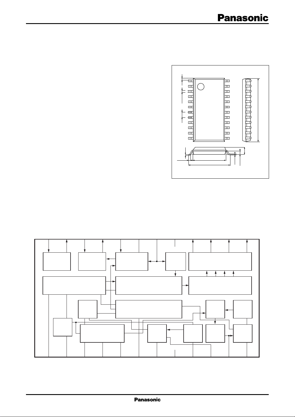
■ Block Diagram
24
23
22
21
20
19
18
17
Unit: mm
14
24
23
22
21
20
19
18
17
16
15
14
13
0.15
0.925
15.3±0.3
2.0±0.2
13
1
2
3
4
5
0.4±0.25 0.451.27
6
7
8
9
10
11
12
0.1±0.1
0.3
CC
V
7.2±0.3
9.4±0.3
SOP024-P-0375A
16
15
1st noise
amp.
Sync.
sepa.
1
ANT
choice
2
2nd noise
amp.
Sync.
control
Horizontal
3
OSC
4
Noise
comparator
select control
switch control
5
Diversity
On/Off
switch
ANT
ANT
switch driver
ANT
select decoder
11
1/12
divider
VCO
12
ANT
Phase
det.
Vertical
OSC
6
7
V-sync.
sepa.
8
Charge
pump
9
10
GND
1
AN5290S ICs for T V
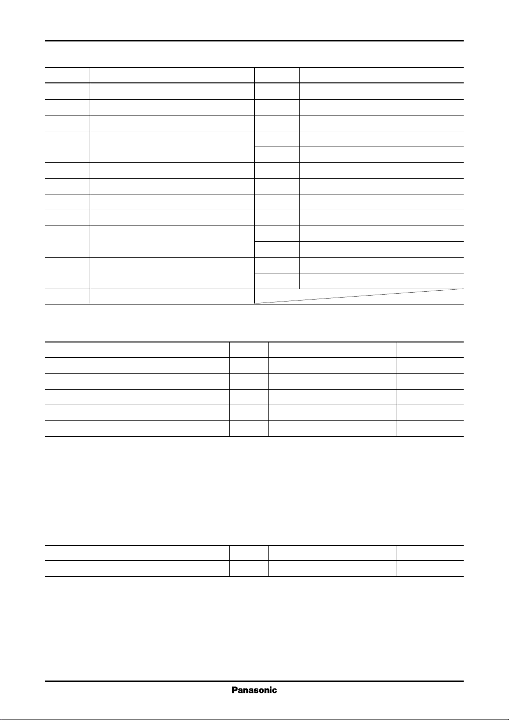
■ Pin Descriptions
Pin No. Description
1 Antenna selection level holding capacitance
2 Sync. separation video signal input
3 Horizontal sync. signal AFC output
4 Horizontal sync. signal oscillation time-
constant setting
5 Horizontal sync. signal output
6 Output for noise canceler
7 Vertical sync. signal output
8 GND
9 Vertical sync. signal separation time constant
setting
10 Vertical sync. signal oscillation time constant
setting
11 Charge pump integral time-constant setting
Pin No. Description
12 VCO oscillation time-constant setting
13 Antenna selection output 4
14 Antenna selection output 3
15 Antenna selection output 2
16 Antenna selection output 1
17 Power supply
18 Noise comparator level setting/diversity off
19 Noise level hold capacitor
20 Noise comparator input
21 2nd noise amplifier output
22 Video clamp input
23 1st noise amplifier output
24 Video signal input
■ Absolute Maximum Ratings
Parameter Symbol Rating Unit
Supply voltage V
Supply current I
Power dissipation
*
Operating ambient temperature T
Storage temperature T
Note) 1. Except for the power dissipation, operating ambient temperature, and storage temperature, all ratings are for Ta = 25°C.
2. In order to protect the IC, do not use the IC by rotating it 180 degrees.
3. To protect the IC, do not connect the open collector pins (pin 5, pin 6, pin 7, pin 13, pin 14, pin 15 and pin 16) directly to
the power supply. Use the protection resistors (1 kΩ or larger for pin 5, pin 6 and pin 7, and 200 Ω or larger for pin 13, pin
14, pin 15 and pin 16). Use the IC within the range of its power dissipation.
: Ta = 80 °C.
4. *
CC
CC
P
D
opr
stg
5.6 V
30.0 mA
168 mW
−30 to +80 °C
−55 to +125 °C
■ Recommended Operating Range
Parameter Symbol Range Unit
Supply voltage V
CC
4.5 to 5.5 V
2
 Loading...