

Panasonic AN5138NK Datasheet
■ Overview
The AN5138NK is an integrated circuit designed for
video-IF and audio-IF processing circuits, in color TV and
VCR.
■ Features
•
By adopting built-in VCO PLL-type video-detector circuit, the high preformance IC-detector system can be
realized for sound multiplex and tele-text broadcasting.
•
Quadrature sound FM detector built-in.
•
Frequency characteristics compensation pin (Pin20)
VCR-switch pin (Pin5)
•
Sound-output level-adjustment pin (Pin25)
1
ICs for TV
AN5138NK
Video IF Amplifier, PLL Detector, AGC, AFC, SIF IC for Color TV
1
2
3
4
5
6
7
8
9
10
11
12
13
14
19
18
17
16
15
20
21
22
23
24
25
26
27
28
26.7±0.3
8.4±0.3
10.16±0.25
3 to 15˚
0.3
+ 0.1
– 0.05
4.8±0.25
1.05±0.25
3.05±0.25
1.778
0.5±0.1
0.9±0.25
Unit : mm
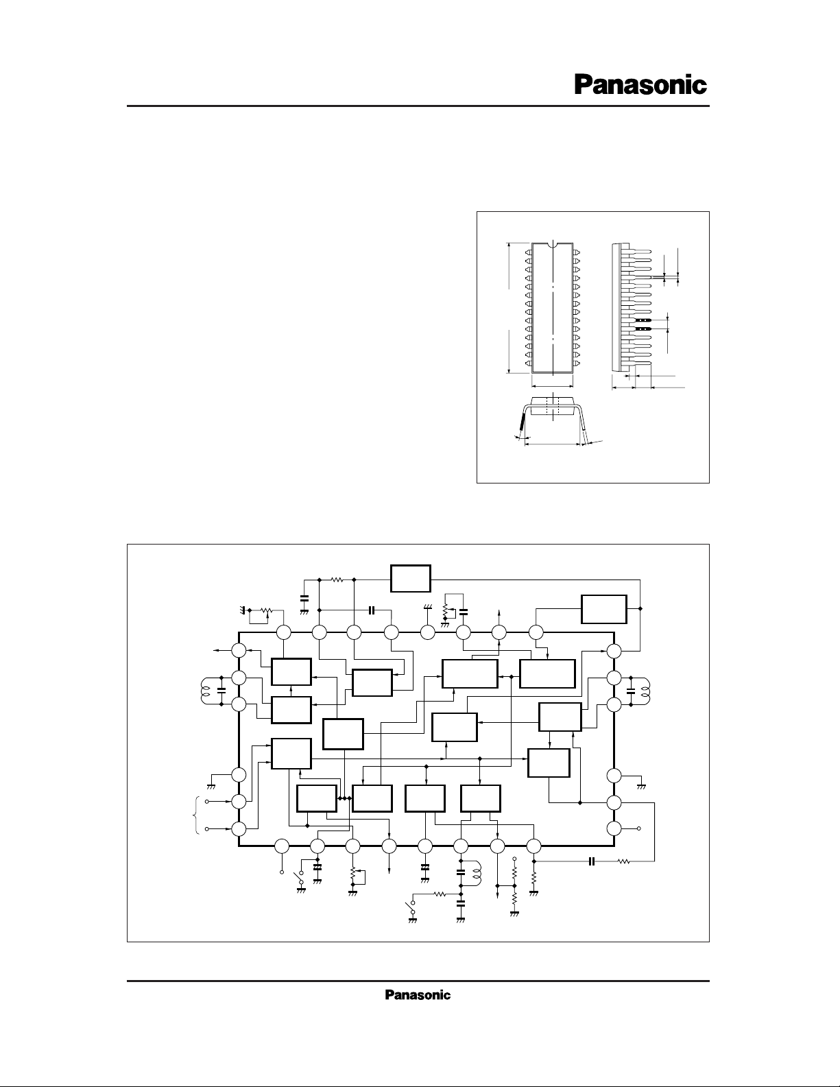
28-Pin Shrunk DIL Plastic Package
■ Block Diagram
SIF
VIF
Amp.
IF
AGC
RF
AGC
Delay
Adj.
Filter
RF
AGC
Out.
Lock
Det.
AFC
SW
Video
Det.
+
–
Video Output
Noise
Inverter
AFC
AFC
Out.
SIF
Trap
17
Video
Inverter
16
15
VCO
APC
Det.
1110987654
14
13
CC
V
12
VCC
Audio Level Adj.
Audio
Output
26
27
28
25 24 23 22 21 20 19 18
Level
Adj.
FM
Det.
VTR
SIF
SW
Amp.
1
RF
AGC
VTR SW
IF
+
AGC
–
Filter
2
3
VCC
IF
Input
2
ICs for TV
AN5138NK
Parameter Symbol Rating Unit
V
CC
V
5-1, 14, 21
V
6-1, 14, 21
V
7-1, 14, 21
V
10-1, 14, 21
I
17
I
19
P
D
T
opr
T
stg
Circuit Voltage
Circuit Current
Supply Voltage
Operating Ambient Temperature
Power Dissipation (Ta=70˚C)
Storage Temperature
Voltage
Current
Temperature
13.8
1,300
–20 to + 70
–55 to + 150
V
mW
˚C
˚C
V
mA
V
V
V
mA
V
4, 12-1, 14, 21
0
V
4, 12-1, 14, 21
0
V
4, 12-1, 14, 21
0
V
4, 12-1, 14, 21
0
–7 + 0.5
–7 + 0.5
V
18-1, 14, 21
V
25-1, 14, 21
I
26
V
V
4, 12-1, 14, 21
0
V
8.0 0
mA
–5 + 0.5
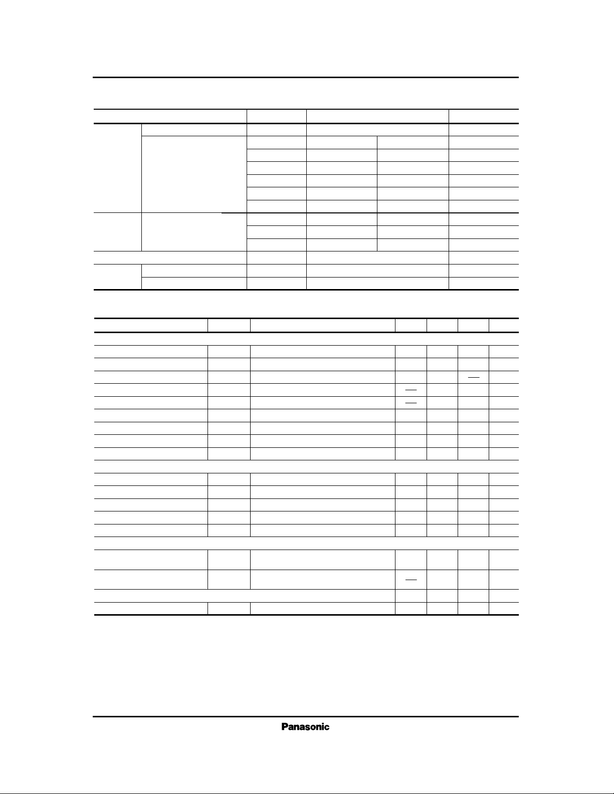
■ Absolute Maximum Ratings (Ta=25˚C)
f= 58.75MHz, Vi= 80dBµ, m= 87.5% 1.9 2.2 2.5 V
P-P
50 70 90 mA
V
O
I4 + I
12
S (IN)
V1 (max.)
DG
G
RFAGC
VO= –3dB
Video detector output
Input sensitivity
Max. allowable input
49
103
5.5
40
53
108
2
6.5
44
57
6
7.5
48
dBµ
dBµ
%
MHz
dB
Parameter minCondition typ max UnitSymbol
IF Amplifier · Detection · AGC · AFC Circuit
Differential gain
Differential phase
Frequency characteristics
RF AGC gain
AFC phase det. sensitivity
AFC center voltage
VCO · APC Circuit
VCO control sensitivity
APC pull-in range (1)
APC pull-in range (2)
SIF Circuit
Circuit current
DP
fc
µ
V
10
β
f
APC (1)
f
APC (2)
f =58.75MHz, Vi= 80dBµ, m= 87.5%
f =58.75MHz, Vi= 80dBµ, m= 87.5%
f =10kHz, Vi=10mV
R
L
= 68kΩ//82kΩ
RL= 68kΩ//82kΩ
V
13
= 2V
2 5 deg
30 45 60
mV/kH
z
4.2 6.5 8.2 V
0.8 1.5 2.5 MHz
3 4.5 6
kH
z/mV
+ 0.85 +1.5 + 2.5 MHz
–3.5 – 2.5 –1.6 MHz
VCO max. variable range (1)
VCO max. variable range (2)
Total detector output
Input limiting voltage
DC Characteristics
∆f
V (1)
∆f
V (2)
V
O
V
i (lim)
VO= –3dB
V13= 3V
f
o
= 4.5MHz, fm= 400Hz
∆f= ±25kHz, Vi=100dBµ
f
o
= 4.5MHz, fm= 400Hz
∆f= ±25kHz, Vi=100dBµ
–3.4 – 2.4 –1.4 MHz
490 620 950 mV
rms
42 47 dBµ
■ Electrical Characteristics (VCC=12V, Ta=25˚C)
 Loading...