

Panasonic AN3969K Datasheet
ICs for VCR
AN3969K
Electronic volume IC for HiFi VCR
■ Overview
The AN3969K is a stereo electronic volume IC
which has been developed for a HiFi video, enabling to switch four inputs of a single channel and
to input from microphone.
■ Features
• Both L/R-independent volume control and balance
control are available
• Switching four inputs with a single channel is
possible
• Electronic volume off function
• Mic. mixing function
■ Applications
• HiFi VCR
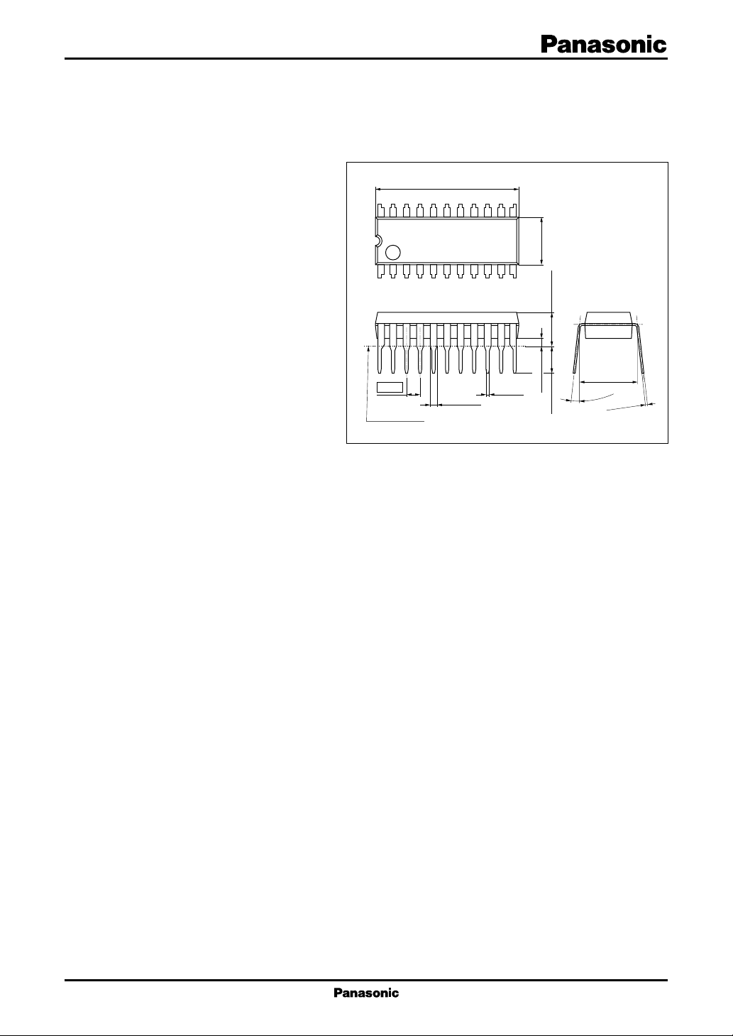
19.1±0.3
22 12
6.35±0.30
111
4.50±0.253.45±0.25
1.778
0.90±0.25
Seating plane
0.5±0.1
SDIP022-P-0300A
1.10±0.25
Unit: mm
7.62±0.25
3° to 15
0.35
°
+0.10
– 0.05
1
AN3969K ICs for V CR
f
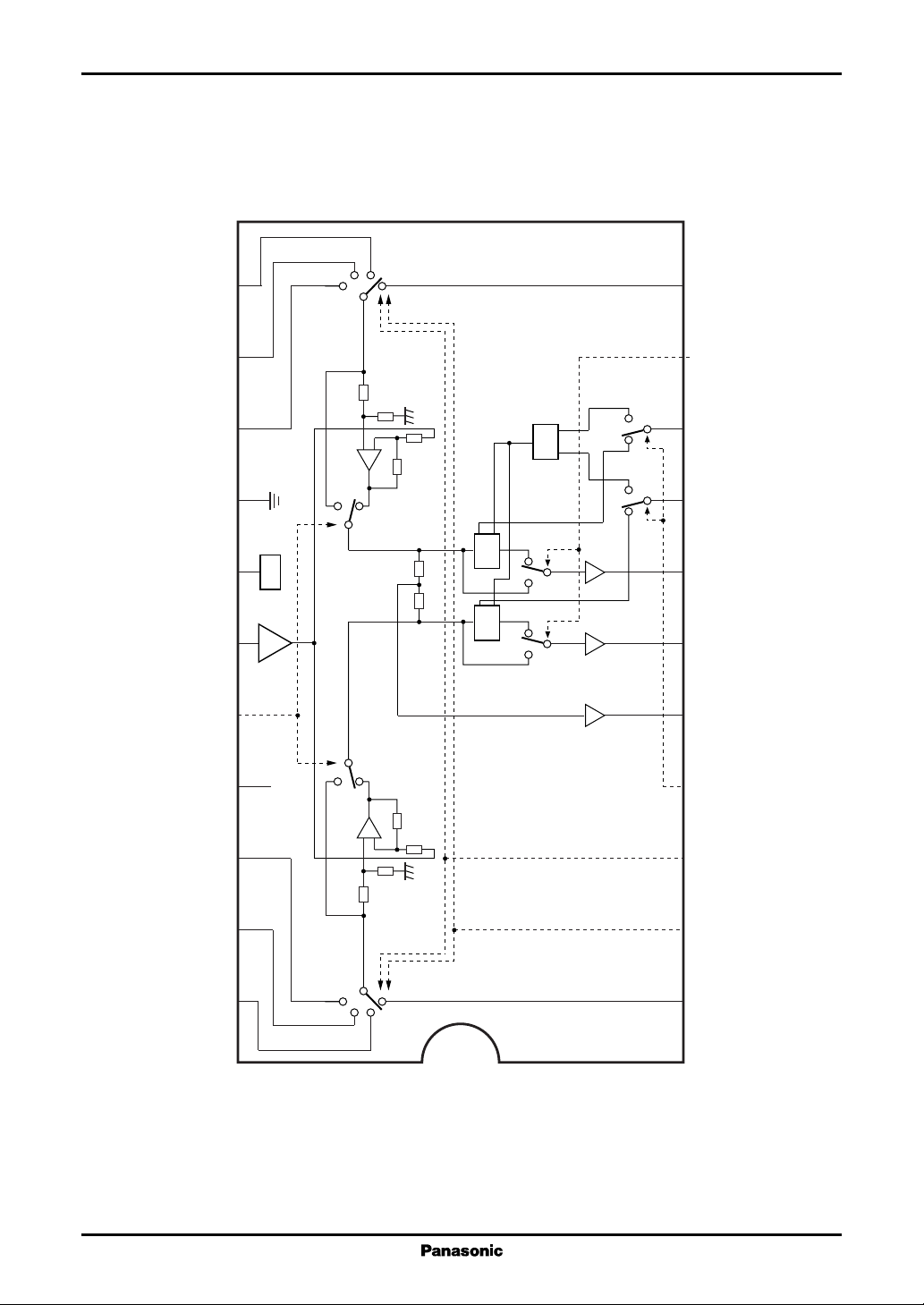
■ Block Diagram
12 11
13
In3 (R)
14
Bal.
CTL
15 8
16 7
REF
Mic. in
CC
REF
V
17 6
Rev.
18 5
19 4
CC
1/2V
Mic. off
Mic. on
EVR on
EVR
(typ. 2.5 V)
EVR off
EVR on
EVR
EVR off
In1 (R)In2 (R)
10
EVR On/Of
Bal.
9
R/bal. CTLIn4 (R)
Vol.
Bal.
L/main CTLGND
Vol.
EVR out (R)V
EVR out (L)
Mix. outMic. On/Off
Vol./bal.V
Mic. on
Mic. off
20 3
21 2
22
In2 (L)
Input SW Input SW
INSEL BIn4 (L)
INSEL AIn3 (L)
1
In1 (L)
2
ICs for VCR AN3969K
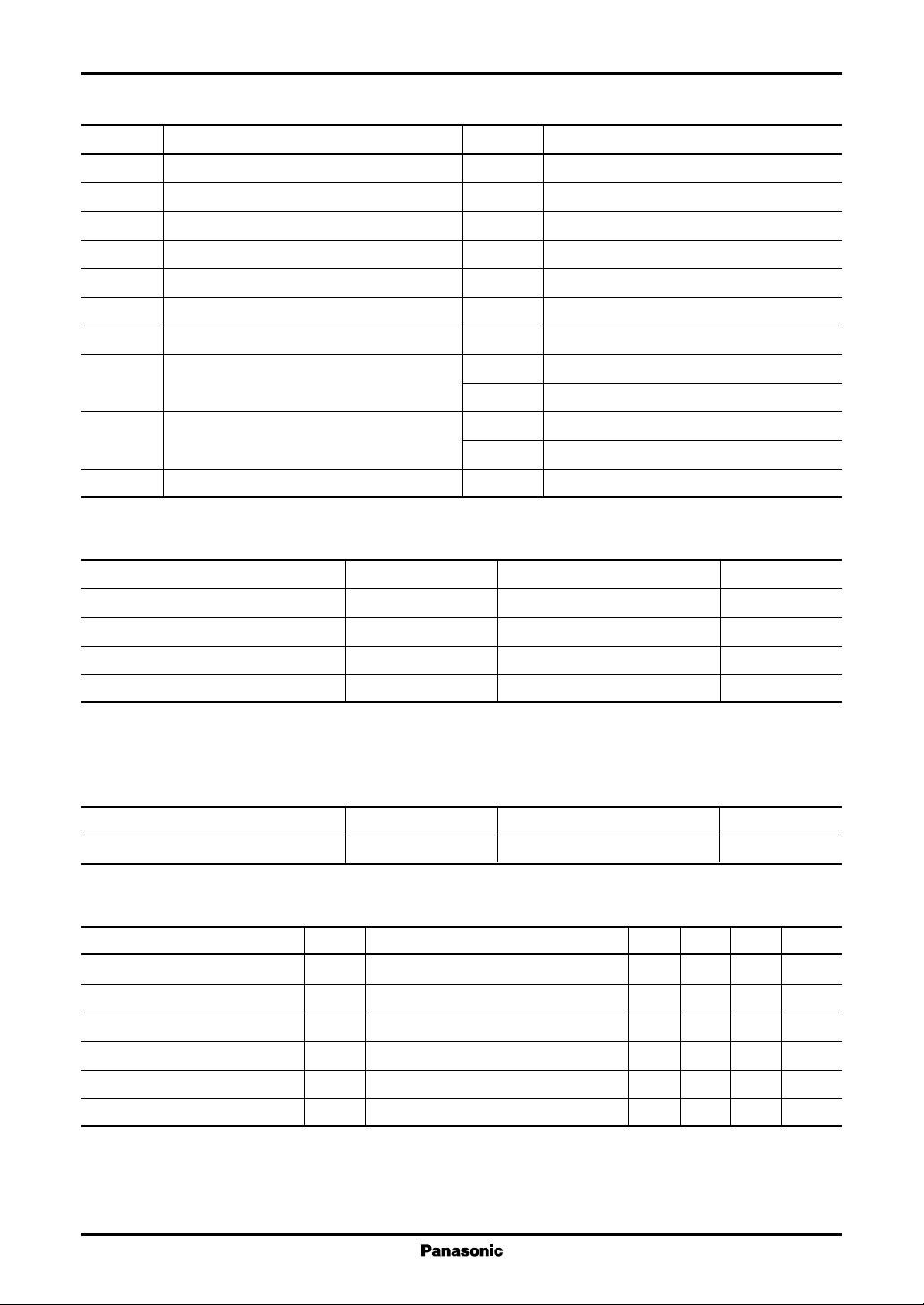
■ Pin Descriptions
Pin No. Description
1 In1 (L-ch.) input pin
2 Input selection control (CTL) A pin
3 Input selection control (CTL) B pin
4 EVR individual/balance mode CTL pin
5 Mix. output pin
6 EVR (L-ch.) output pin
7 EVR (R-ch.) output pin
8 Main volume adjustment pin for individual
mode L-ch./balance mode
9 Balance volume adjustment pin for
individual mode R-ch./balance mode
10 EVR On/Off CTL pin
■ Absolute Maximum Ratings
Parameter Symbol Rating Unit
Supply voltage V
1, *2
Power dissipation
Operating ambient temperature
Storage temperature
Note)*1: Except for the power dissipation, operating ambient temperature and storage temperature, all ratings are for Ta = 25°C.
2: The power dissipation shown is the value for Ta = 75°C.
*
*
1
*
1
*
CC
P
D
T
opr
T
stg
Pin No. Description
11 In1 (R-ch.) input pin
12 In2 (R-ch.) input pin
13 In3 (R-ch.) input pin
14 In4 (R-ch.) input pin
15 GND pin
16 V
(1/2VCC) pin
REF
17 Mic. input pin
18 Mic. On/Off CTL pin
19 VCC (5 V) pin
20 In4 (L-ch.) input pin
21 In3 (L-ch.) input pin
22 In2 (L-ch.) input pin
6.0 V
186 mW
−20 to +75 °C
−55 to +150 °C
■ Recommended Operating Range
Parameter Symbol Range Unit
Supply voltage V
CC
4.5 to 5.5 V
■ Electrical Characteristics at VCC = 5 V, pin 8 = 3 V, pin 9 = 3 V, Ta = 25°C
Parameter Symbol Conditions Min Typ Max Unit
Circuit current 1 I
Circuit current 2 I
EVR out level L VEOLTypical input −23 −20 −17 dBs
EVR out level R VEORTypical input −23 −20 −17 dBs
EVR out distortion ratio L TEOLTypical input 0.2 %
EVR out distortion ratio R TEORTypical input 0.2 %
Note)1.Unless otherwise specified, set a mode to In1 input selection, EVR on, EVR individual CTL, mic. off and input a typical input
that is In1 input, VIN = −20 dBs, fIN = 1 kHz and L/R simultaneous input.
2. Unless otherwise specified, measure EVR out L for L-ch. parameter and EVR out R for R-ch. parameter.
EVR individual CTL mode with no signal
VOL
EVR balance mode with no signal 19 25 31 mA
BAL
14 18 23 mA
3
 Loading...