


Panasonic AN3370K Datasheet
ICs for VCR
■ Overview
The AN3370K can amplify high-frequency current generated by the built-in oscillator and drive the Flying-erase
head. This IC also allows to set an oscillation frequency
and an output current optionally with external constants
according to the erase head.
■ Features
•
Built-in high-accuracy, stable oscillator.
•
Capable of varying output current value and an oscillation frequency with external constants.
AN3370K
Flying-Erase IC
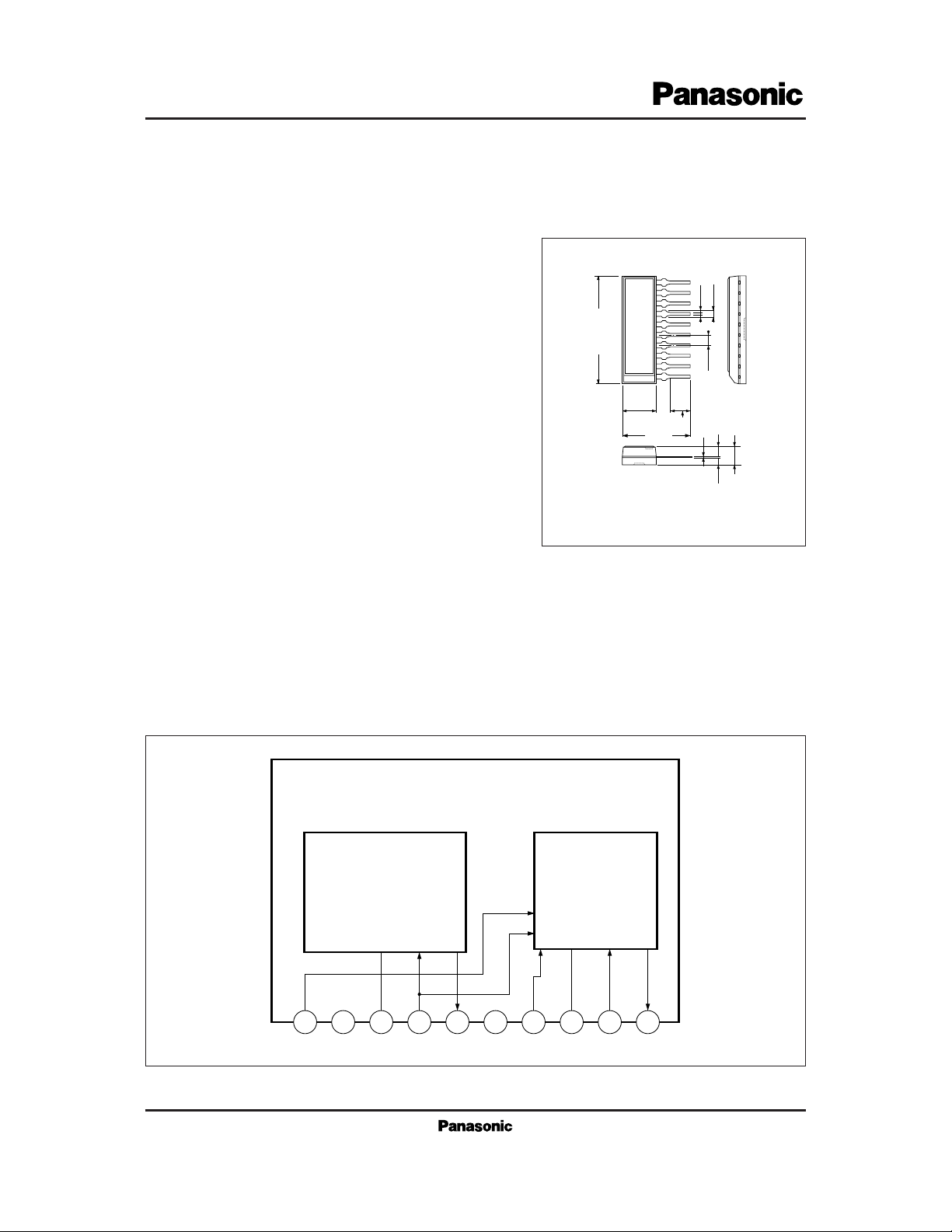
■ Block Diagram
10
1.1±0.25
1.65±0.25
0.25
3.0±0.3
3.5±0.25
0.5
1.1
1.778
+ 0.1
– 0.05
Unit : mm
1
10-Pin Shrunk SIL Plastic Package (10-SSIP)
6.0±0.3
(12.0)
18.24±0.3
Output
Driver
1 2 3 4 5 6 7 8 9 10
V
CC
GND
OSC
ICs for VCR
AN3370K
V
O1
f
O
V1= 5V, RL= 300Ω
V
1
= 5V, RL= 300Ω
Supply current
Oscillation output amplitude
Oscillation frequency
8
11911.55 12.1
V
PP
MHz
Parameter minCondition typ max UnitSymbol
V
O2
V1= 0V, RL= 300Ω
Oscillation output amplitude
10 mV
PP
V
1H
Flying ON
3.5 V
V
1L
Flying OFF
0.8 V
I
CC
V1= 5V 20 28 36 mA
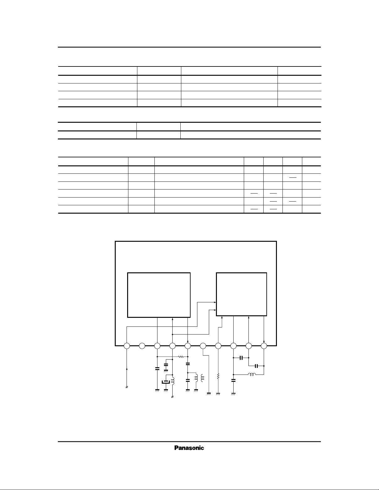
■ Electrical Characteristics (VCC=12V, Ta=25˚C)
1 2 3 4 5 6 8 107
1.8kΩ
0.01µF
V
CC=12V
0.01
µF
4µH
68pF
68pF
56pF
100µF
4.7µH
33pF
0.01µF
5.1kΩ
Output
Driver
OSC
9
Flying Control Voltage
Note) Do not apply a voltage (0V included) to the Pin2 from the external.
Parameter Symbol Rating Unit
V
CC
P
D
T
opr
T
stg
Power dissipation
Supply voltage
Operating ambient temperature
Storage temperature
12.6
500
– 20 to + 70
– 55 to +150
V
mW
˚C
˚C
■ Absolute Maximum Ratings (Ta=25˚C)
Parameter Symbol Range
Operating supply voltage range
V
CC
10.5V to 12.5V
■ Recommended Operating Range (Ta = 25˚C)
■ Application Circuit