

/
/
/
G
Operating Instructions/Bedienungsanleitung
/
/
/
Mode d’emploi/Istruzioni per l’uso
Instrucciones de funcionamiento
操作手册/取扱説明書
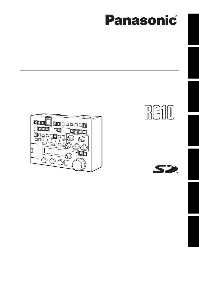
Remote Control Unit/Fernsteuereinheit
Module de télécommande
Unità per il comando a distanza/Unidad de control remote
摄像机遥控器 / リモートコントロールユニット
Model No. AJ-
ENGLISHDEUTSCHFRANÇAISITALIANOESPAÑOL
Before operating this product, please read the instructions carefully and save this
manual for future use.
Bitte lesen Sie vor Inbetriebnahme dieses Produkts die Anleitungen sorgfältig durch
und bewahren Sie dieses Handbuch für spätere Verwendung auf.
Avant de vous servir de ce produit, veuillez lire attentivement les instructions et
enregistrer ce manuel pour une utilisation ultérieure.
Prima di utilizzare questo prodotto, leggere attentamente le istruzioni di questo
manuale e conservarlo per riferimento futuro.
Antes de poner este producto en funcionamiento, lea atentamente las instrucciones
y conserve este manual para uso futuro.
使用本产品前,请仔细阅读本说明书,并妥善保存以备日后参考。
お買い上げいただき、まことにありがとうございました。
この取扱説明書をよくお読みの上、正しくお使いください。
特に「安全上のご注意」は、ご使用前に必ずお読みいただき、安全にお使いください。
お読みになったあとは、保証書と一緒に大切に保管し、必要なときにお読みください。
F0706T0 -F @
Printed in Japan
VQT1A65
中
文
日
本
語
Read this first!
For General
DO NOT REMOVE PANEL COVERS
BY UNSCREWING THEM.
To reduce the risk of electric shock, do
not remove the covers. No user
serviceable parts inside.
Refer servicing to qualified service
personnel.
WARNING:
z TO REDUCE THE RISK OF FIRE OR
SHOCK HAZARD, DO NOT EXPOSE
THIS EQUIPMENT TO RAIN OR
MOISTURE.
z TO REDUCE THE RISK OF FIRE OR
SHOCK HAZARD, KEEP THIS
EQUIPMENT AWAY FROM ALL
LIQUIDS. USE AND STORE ONLY IN
LOCATIONS WHICH ARE NOT
EXPOSED TO THE RISK OF DRIPPING
OR SPLASHING LIQUIDS, AND DO
NOT PLACE ANY LIQUID CONTAINERS
ON TOP OF THE EQUIPMENT.
CAUTION:
TO REDUCE THE RISK OF FIRE OR
SHOCK HAZARD AND ANNOYING
INTERFERENCE, USE THE
RECOMMENDED ACCESSORIES ONLY.
CAUTION:
In order to maintain adequate ventilation,
do not install or place this unit in a
bookcase, built-in cabinet or any other
confined space. To prevent risk of
electric shock or fire hazard due to
overheating, ensure that curtains and any
other materials do not obstruct the
ventilation.
Note:
The rating plate is on the underside of the
unit.
E-1
indicates safety information.
Read this first! (Continued)
The lightni
d
For USA
CAUTION
RISK OF ELECTRIC SHOCK
DO NOT OPEN
CAUTION: TO REDUCE THE RISK OF
ELECTRIC SHOCK, DO NOT REMOVE COVER
NO USER SERVICEABLE PARTS INSIDE.
REFER TO SERVICING TO QUALIFIED
(OR BACK).
SERVICE PERSONNEL.
symbol, within an equilateral
triangle, is intended to alert the user
to the presence of uninsulated
“dangerous voltage” within the
product’s enclosure that may be of
sufficient magnitude to constitute a
risk of electric shock to persons.
The exclamation point within an
equilateral triangle is intended to
alert the user to the presence of
important operating and
maintenance (service) instructions in
the literature accompanying the
appliance.
ng flash with arrowhea
indicates safety information.
ENGLISH
FCC Note:
This equipment has been tested and found
to comply with the limits for a class A digital
device, pursuant to Part 15 of the FCC
Rules. These limits are designed to provide
reasonable protection against harmful
interference when the equipment is operated
in a commercial environment. This
equipment generates, uses, and can radiate
radio frequency energy, and if not installed
and used in accordance with the instruction
manual, may cause harmful interference to
radio communications. Operation of this
equipment in a residential area is likely to
cause harmful interference in which case the
user will be required to correct the
interference at his own expense.
Warning:
To assure continued FCC emission limit
compliance, the user must use only shielded
interface cables when connecting to external
units. Also, any unauthorized changes or
modifications to this equipment could void
the user’s authority to operate it.
E-2

Table of Contents
Read this first! ................................ 1
General............................................4
Features .......................................... 4
Accessories ....................................4
Connection......................................5
System configuration.....................5
Parts and functions........................ 6
Front panel ........................................6
Rear panel.......................................15
Basic operations ..........................16
When the power is on......................16
To enable the buttons/volumes .......16
To disable buttons/volumes.............16
Operation of the camera recorder ...17
Operation of the camera
using the unit volume ......................18
Operation of the scene file ..............19
Operation for recording ...................20
Saving/Loading of scene files onto
the SD memory card ....................21
Handling methods
for the SD memory card ..................21
To load data from the card ..............21
To write data on the card.................22
To delete files from the card............22
Initialization of the card....................22
Menu operation.............................23
Operations using the LCD panel .....23
Operation of the camera recorder
menu ...............................................23
Adjustment of functions
on the unit........................................23
Menu item ..................................... 24
Menu ...............................................24
BLACK.............................................24
FLARE.............................................25
GAMMA...........................................25
WHITE.............................................25
KNEE...............................................27
SHUTTER .......................................27
SHAD ..............................................28
MATRIX...........................................28
DTL..................................................29
SKIN DTL ........................................29
FUNC ..............................................30
SYSTEM..........................................31
Connection cable ......................... 32
Confirmation of software
version .......................................... 32
Specifications............................... 33
E-3
General
The AJ-RC10G (hereinafter called “the unit”) is a remote control unit connected to the camera recorder.
The unit controls the camera recorder from the controller and is capable of changing numerical values
in the menu. Coverage can be extended by 50m by using the dedicated cable.
Features
z For some frequently functions on the camera unit, dedicated switches are provided for direct
operation.
z By switching to the recorder mode, the camera recorder can be controlled directly through the VTR
operation switch. In addition, recording can be disabled using a switch.
z Frequently used menus can be set by accessing the menus on the LCD panel of the unit. It is also
possible to display the time code on the LCD panel.
z Down-converted images with characters are output from the VIDEO OUT connector. The menus can
be operated on the main unit of the camera recorder by connecting the external monitor.
z By switching to the scene file mode, it is possible to operate the scene file. Data of revised scene files
can be stored on an SD memory card.
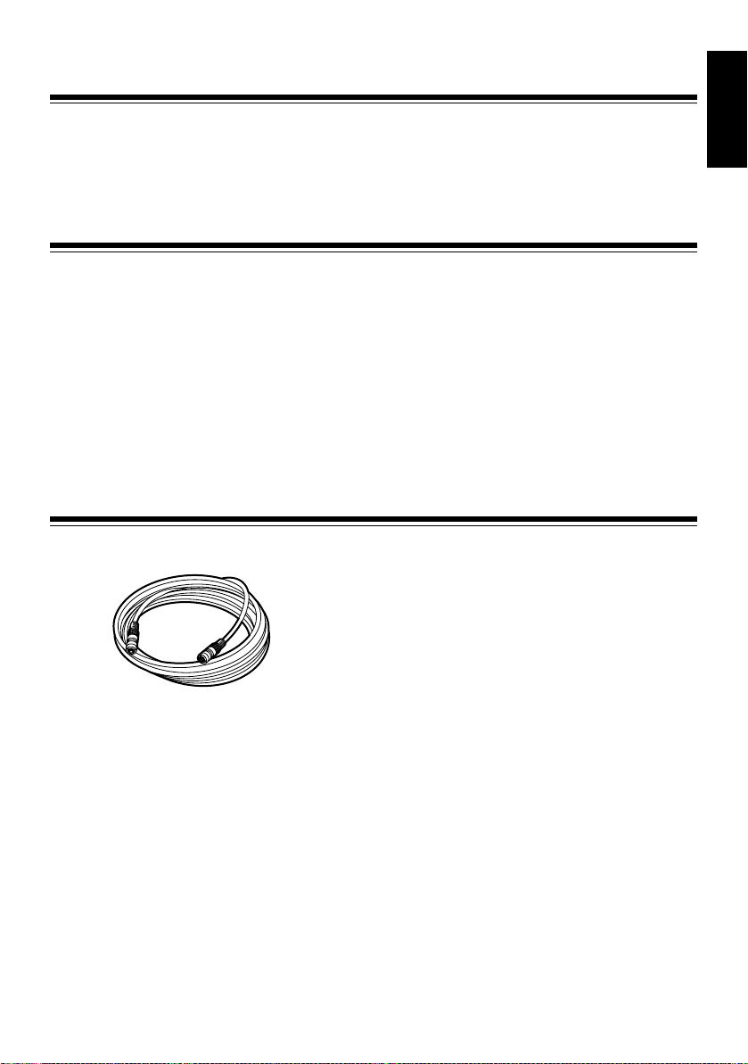
Accessories
Connection cable (10 m)
ENGLISH
E-4
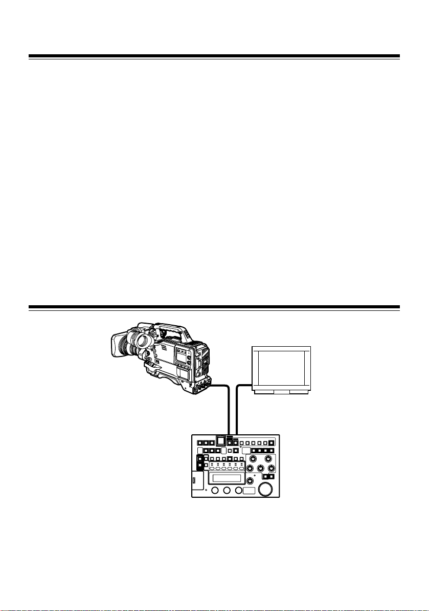
Connection
1
While the power supply of the camera
recorder is turned off, connect the RCU 10pin connector of the camera recorder to the
unit with the connection cable.
If settings are made from the camera menu,
set the frequency to the frame frequency of
the camera recorder and connect an NTSC
or PAL monitor.
2 After turning on the camera recorder power,
turn the unit power on.
System configuration
<Notes>
z The frame frequency of the camera recorder
must be switched before connecting the unit to
the camera recorder.
At VIDEO output, NTSC signals are output for
60 Hz operation, while PAL signals are output
for 50 Hz operation.
z The settings for FUNC on the menu determine
whether the camera recorder’s settings, which
are adjusted when the unit is connected, are
returned to the settings before connecting the
unit or to the state after adjustment, when the
unit is disconnected from the camera recorder.
z Do not forcefully pull the connected cable.
When the camera recorder is used while it is
being moved, the cable must be fixed to the
tripod or the handle of the camera recorder so
that no force is applied directly to the
connector.
Monitor
Camera recorder
Dedicated 10-pin cable Video cable
Camera connection connector VIDEO OUT connector
AJ-RC10G
<Note>
To determine whether the camera recorder supports the use of the unit, consult our sales dealers or the
operation manual of the camera recorder.
E-5

Parts and functions
Front panel
Panel part
!3"
!2"
!1" POWER button
ON/OFF switch of the main power supply of
the main unit
!2" PANEL ACTIVE button
For controlling which panel operations are
available
When the lamp is on:
The panel operations are available.
When the power is on, the unit is on.
When the lamp is off:
Only the POWER button and the PANEL
ACTIVE button are available; all other
button operations are disabled.
Turning on the self-lighting buttons and the
LED display, which indicate the operating
conditions of the camera recorder, follow the
operating conditions of the camera recorder.
!1"
!3" SW ACTIVE button
For enabling button/switch operations
When the lamp is on:
The button/switch operations are
enabled.
When the lamp is off:
Only the POWER button, PANEL
ACTIVE button, SW ACTIVE button, VR
ACTICVE button, AUTO IRIS button,
M.PED volume, and IRIS volume are
available; all other operations are
disabled.
Turning on the self-lighting SW and the LED
display, which indicate the operating
conditions of the camera recorder, follow the
operating conditions of the camera recorder.
ENGLISH
E-6

Parts and functions (Continued)
H
Camera recorder/Scene file operation
!1"
!2"
!3"
!4"
!5"
!6"
!7"
!8"
!9"
!1" RECORDER ENABLE button
For switching between the recorder mode
and the scene file mode
When the lamp is on:
Recorder mode
Buttons from !3" to !8" are operated as
control buttons for the recording.
When the lamp is off:
Scene file mode
Buttons from !3" to !8" are operated as the
buttons for reading and storing scene
files. When the power is turned on, the
unit is in this state.
!2" REC.INH/LOAD button
In recorder mode:
When the lamp is on, the REC S/S button !8"
is inhibited.
However, even if the unit is in the recording
inhibition state, operation of the USER
button assigned REC function and operation
of the REC button on the camera recorder
are enabled.
The lamp is off when the power is on.
In scene file mode:
The button is operated as the LOAD switch
of the scene file. Data are retrieved from the
file on the remote controller.
!3" REW/1 button
In recorder mode:
This button is operated in the same way as
the REW button on the camera recorder,
and the lamp is on when a tape is rewinding.
In the scene file mode:
1 is selected as the number for the scene
file to be saved or loaded.
!4" FF/2 button
In recorder mode:
This button is operated in the same way as
the FF button on the camera recorder, and
the lamp is on when a tape is fastforwarding.
In scene file mode:
2 is selected as the number for the scene
file to be saved or loaded.
!5" STOP/3-button
In recorder mode:
This button is operated in the same way as
the STOP button on the camera recorder,
and the lamp is on when a tape stops.
In scene file mode:
3 is selected as the number for the scene
file to be saved or loaded.
!6" PLAY/4-button
In recorder mode:
This button is operated in the same way as
the PLAY button on the camera recorder,
and the lamp is on when a tape is replayed.
If the button is pressed again during tape
replay, it changes to replay/pause, and the
lamp flashes.
If the button is pressed one more time, the
unit returns to replaying, and the lamp is on
continuously.
In scene file mode:
4 is selected as the number for the scene
file to be saved or loaded.
E-7

Parts and functions (Continued)
!7" CHECK/5-button
In recorder mode:
This is the recording confirmation button. If
the button is pressed when recording is
paused, the recording can be checked.
The lamp flashes when the tape is rewound
and is turned on when the tape is replayed.
In scene file mode:
5 is selected as the number for the scene
file to be saved or loaded.
!8" REC S/S / SAVE button
In recorder mode:
This is the start/stop button for recording.
This button is operated in the same way as
the REC START button on the camera
recorder, and the lamp is on during
recording.
In scene file mode:
This button is operated in the same way as
the SAVE button for scene data.
The current data are stored in the file on the
remote controller, which is selected by using
the buttons from !3" to !7".
!9" RECORDER WARNING lamp
This lamp flashes or is turned on when an
error occurs on the camera recorder, just
like the WARNING lamp on the camera
recorder. For details, refer to the operation
manual of the camera recorder.
ENGLISH
E-8

Parts and functions (Continued)
Basic camera operations
!1"
!5"
!4"
!2"
!3"
!7"
!6"
!1" USER MAIN button
This button has the same function as the
USER MAIN switch on the camera recorder.
The lamp is on only when the button is
pressed.
<Note>
Functions assigned to the USER MAIN
button are selected in the menu of the
camera recorder or the unit.
!2" USER1 button
This button has the same function as the
USER1 switch on the camera recorder. The
lamp is on only when the button is pressed.
<Note>
Functions assigned to the USER1 button
are selected in the menu of the camera
recorder or the unit.
!3" USER2 button
This button has the same function as the
USER2 switch on the camera recorder. The
lamp is on only when the button is pressed.
<Note>
Functions assigned to the USER2 button
are selected in the menu of the camera
recorder or the unit.
!8"
!4" PRE/A/B button
Operations of this button are the same as
for the WHITE BAL switch on the camera
H
recorder to select PRE, A or B.
The state will switch to “PRE” # “A” # “B”
# “PRE” step by step every time the button
is pressed.
When the power is turned on, the unit is in
the state it was before turning off the power.
!5" PRE/A/B display
This displays the WHITE BAL selection on
the camera recorder using P/A/b
!6" FILTER ND/CC button
This switches the FILTER display on the CC/
ND display !7" between ND filter and the CC
filter alternately.
!7" CC/ND Display
This displays the ND or CC selection using
the FILTER ND/CC !6" button.
For the ND filter display, the filter position is
indicated with 1/2/3/4.
For the CC filter display, the filter position is
indicated with A/b/C/d.
For the single filter, filter switching is
disabled. 1/2/3/4 is displayed depending on
the filter position.
When the power is on, the ND filter position
is displayed.
!8" BAR ON/OFF button
This button switches the output from the
camera recorder between the color bar and
the camera signals.
When the output from the camera recorder
is the color bar, the lamp is on; otherwise, it
is off.
When the power is turned on, the unit is in
the state it was before turning off the power.
E-9

Parts and functions (Continued)
Basic camera operations (Continued)
!10"
!9"
H
!11"
!12"
!13"
!9" GAIN display
This displays the image gain of the camera
recorder. The initial value is the gain value
at the time when the GAIN switch on the
camera recorder was set to “L”.
!10" M.GAIN 3 button
When this button is pressed, the image gain
of the camera recorder is increased.
The lamp is on only when this button is
pressed.
!11" M.GAIN 4 button
When this button is pressed, the image gain
of the camera recorder is reduced.
The lamp is on only when this button is
pressed.
!12" AWB button
When this button is pressed, the camera
recorder starts the AWB (Auto White
Balance) operation.
When this button is pressed during AWB
operation, the AWB operation will forcibly
terminate.
The lamp is on during AWB operation and
off when the operation is completed
correctly. If AWB operation finishes
incorrectly, the lamp will flash for 5 seconds
and then turn off.
!13" ABB button
When this button is pressed, the camera
recorder starts the ABB (Auto Black
Balance) operation.
When this button is pressed during the ABB
operation, the ABB operation will forcibly
terminate.
The lamp is on during ABB operation and off
when the operation is completed correctly. If
the ABB operation finishes incorrectly, the
lamp will flash for 5 seconds and then turn
off.
ENGLISH
E-10

Parts and functions (Continued)
Basic camera operations (Continued)
!16" !17" !18"
!15"
!14"
!14" MATRIX ON button
This button switches the matrix function ON/
OFF. Even if the MATRIX is set to “OFF” in
the menu of the camera recorder, it switches
to “ON” when this button is pressed. “A” and
“B” of the MATRIX TABLE and the settings
for the table can be set with the menu on the
unit.
The lamp is on when the MATRIX is ON;
otherwise, the lamp is off.
!15" DTL OFF button
This button switches the DETAIL function of
the camera recorder ON/OFF. Even if the
DTL item in the menu of the camera
recorder is set to “OFF,” it will turn on when
this button is pressed.
When the unit is connected to the camera
recorder, this becomes the menu value for
the camera recorder.
The lamp is on when the DETAIL is set to
OFF; otherwise, the lamp is off.
!16" A.KNEE ON button
This button switches the AUTO KNEE
function ON/OFF. If the AUTO KNEE SW is
set to “OFF” in the menu of the camera
recorder, it is impossible to turn it ON using
this button.
When the power is turned on, the unit is in
the state it was before turning off the power.
The lamp is on when the AUTO KNEE
function is ON; otherwise, the lamp is off.
!17" HIGH COLOR ON button
This button switches the HIGH COLOR
function ON/OFF. Even if the HIGH COLOR
is set to “OFF” in the menu of the camera
recorder, it will turn on when this button is
pressed.
When the unit is connected to the camera
recorder, this becomes the menu value of
the camera recorder.
The lamp is on when the HIGH COLOR
function is on; otherwise, the lamp is off.
!18" SHT ON button
This button switches the shutter function
ON/OFF.
The shutter speed, when this function is on,
is selected in the menu of the unit.
The lamp is on when the shutter function is
on; otherwise, the lamp is off.
When the power is turned on, the unit is in
the state it was before turning off the power.
E-11

Parts and functions (Continued)
Volume settings
!2"
!3"
!4"
!11"
!7"
!8"
!1" VR ACTIVE button
This is a button to approve/inhibit operations
of the GAIN volumes from !2" to !3" and the
BLACK volumes from !4" to !6".
When the power of the unit is on, it inhibits
operations.
The lamp is on when the approving/
operations are activated; otherwise, the
lamp is off.
!2" R GAIN volume
This adjusts the Rch gain.
The absolute value/relative value mode can
be switched in the GAIN-VR-MODE item of
the WHITE menu of the unit. When reading
card data and scene file data, this will be in
the relative value mode. The operations for
the B GAIN volume are the same.
!3" B GAIN volume
This adjusts the Bch gain.
!5"
!6"
!9"
!1"
!10"
!4" R BLACK volume
This adjusts the Rch black level.
Switching between the relative value mode
and the absolute value mode is executed in
the menu BLACK-VR-MODE of the unit.
When reading card data and scene file data,
this will be in the relative value mode.
It is possible to select either Flare or
Pedestal for item adjustment in the Menu
BLACK-VR-CONTROL item on the unit. The
operations for the G BLACK volume and B
BLACK volume are the same.
!5" G BLACK volume
This adjusts the Gch black level.
!6" B BLACK volume
This adjusts the Bch black level.
!7" M.PED volume
This adjusts the master pedestal level. The
adjustment range is between the minimum
value of –200 and the maximum value of
+200 with a center value of 0.
!8" IRIS display
This displays the iris of the camera.
!9" AUTO IRIS button
This turns on the auto iris function.
When the power is turned on, the unit is in
the state it was before turning off the power.
The lamp is on when the unit commands the
auto iris operation in the camera; otherwise,
the lamp is off.
!10" IRIS volume
This adjusts the iris of the camera.
When the AUTO IRIS button !9" is set to
OFF, it is possible to move the iris from
CLOSE to OPEN by turning this to the right.
ENGLISH
!11" EXT alarm lamp
This lamp is on when the lens extender is
inserted.
E-12

Parts and functions (Continued)
Menu operation of the unit
!9"
!15"
!13"
!18"
!16"
!3"
!4"
!6"
!7"
!12"
!10"
!20"
!21"
!2"
!5"
!8"
!1"
!11"
!14"
!1" LCD panel
This displays the menus for items selected
with the menu operation buttons !2", !5", !8",
!11", !14" and !17".
This is also capable of displaying the time
code.
!2" BLACK/SHAD button
This selects the large item displayed on the
LCD panel. The display will switch to
BLACK # SHAD # before entering into the
menu mode # BLACK step by step every
time the button is pressed.
!3" BLACK lamp
This lamp is on when BLACK is selected on
the LCD panel.
!4" SHAD lamp
This lamp is on when SHAD is selected on
the LCD panel.
!5" FLARE/MATRIX button
This button selects the large item displayed
on the LCD panel.
The display will switch to FLARE # MATRIX
# before entering into the menu mode #
FLARE step by step every time the button is
pressed.
!19"
!17"
!6" FLARE lamp
This lamp is on when FLARE is selected on
the LCD panel.
!7" MATRIX lamp
This lamp is on when MATRIX is selected on
the LCD panel.
!8" GAMMA/DTL button
This selects the large item displayed on the
LCD panel. The display will switch to
GAMMA # DTL # before entering the
menu mode # GAMMA step by step every
time the button is pressed.
!9" GAMMA lamp
This lamp is on when GAMMA is selected
on the LCD panel.
!10" DTL lamp
This lamp is on when DTL is selected on the
LCD panel.
!11" WHITE/SKIN DTL button
This selects the large item displayed on the
LCD panel. The display will switch to WHITE
# SKIN DTL # before entering the menu
mode # WHITE step by step every time the
button is pressed.
!12" WHITE lamp
This lamp is on when WHITE is selected on
the LCD panel.
!13" SKIN DTL lamp
This lamp is on when SKIN DTL is selected
in on the LCD panel.
E-13

Parts and functions (Continued)
!14" KNEE/FUNC button
This selects the large item displayed on the
LCD panel. The display will switch to KNEE
# FUNC # before entering the menu mode
# KNEE step by step every time the button
is pressed.
!15" KNEE lamp
This lamp is on when the KNEE is selected
on the LCD panel.
!16" FUNC lamp
This lamp is on when the FUNC is selected
on the LCD panel.
!17" SHUTTER/SYSTEM button
This selects the large item displayed on the
LCD panel. The display will switch to
SHUTTER # SYSTEM # before entering
the menu mode # SHUTTER step by step
every time the button is pressed.
!18" SHUTTER lamp
This lamp is on when the SHUTTER is
selected on the LCD panel.
!19" SYSTEM lamp
This lamp is on when the SYSTEM is
selected on the LCD panel.
!20"3 button
!21"
4
button
This button switches the display on the LCD
panel and selects a medium item from the
menu of the unit.
The lamp is on when the button is pressed
and off when the button is released.
!22"
!23"
!27"
!24"
!25"
!22" MENU ON button
To open the menu on the camera recorder,
press this button continuously for 3 seconds.
In this case, a message “CAMERA MENU
OPEN” is displayed on the LCD panel. The
lamp is on at this time, and operations of the
menu and the scene file on the unit are not
available.
If this button is pressed when the menu of
the camera recorder is open, the menu will
close.
!23" CHARA ON button
This selects whether any characters are
overlaid on the video signals output from the
VIDEO OUT connector of the unit.
When the power is on, the unit is in the state it
was before turning off the power.
The lamp is on when characters are loaded
onto the signals, while it is off when
characters are not loaded.
!24" Rotary encoder 1
!25" Rotary encoder 2
!26" Rotary encoder 3
This is used for operating the menu on the
LCD panel or the camera menu.
The camera menu is operated by using the
right rotary encoder.
The operation of the rotary encoder is the
same as the JOG switch on the camera (+,
–, PUSH)
!27" Vacant button
This is a vacant button for which no function
is assigned.
ENGLISH
!26"
E-14

Parts and functions (Continued)
Rear panel
!6"
!1" Camera connection connector
To connect the 10-pin camera control cable.
1
8
2
7
910
3
6
5
4
!1"
!2"
VIDEO OUT
CAM RCU
CABLE
FREQUENCY LEVEL
50m
10m
!3"
!5"
!4"
Pin No. Signal
1CAM DATA (H)
2CAM DATA (C)
3 CAM CONT (H)
4 CAM CONT (L)
5 ECU_ON
6Video input
7 GND (Video)
8 Standby
9+12 V (IN)
10 GND
!6" Covering screw
The unit can be used when the four screws
are removed. However, do not leave the unit
without these screws for long periods of
time. When the screws are not in use, they
must be stored safely.
<Note>
Do not remove the four screws on the back
panel.
!2" VIDEO OUT connector
An NTSC or PAL monitor is connected for
operating the menu on the main unit of the
camera recorder.
!3" Cable length selector switch
This switch is on for a 50 m cable.
!4" Frequency characteristics
adjustment volume
This adjusts the frequency characteristics of
the VIDEO signals.
!5" Level adjustment volume
This adjusts the level of the VIDEO signals.
E-15

Basic operations
When the power is on
When the POWER button is pressed, the lamp
for the PANEL ACTIVE button is on, and the
settings of the camera recorder are read into the
unit.
The respective numerical values are displayed
on the PRE/A/B display, CC/ND display, GAIN
display, and the IRIS display, while R GAIN and B
GAIN are displayed on the LCD panel.
In this case, only the PANEL ACTIVE button, the
SW ACTIVE button, the VR ACTIVE button, the
AUTO IRIS button, M.PED volume and the IRIS
volume can be operated from the unit, while
other buttons and volumes are not operative.
However, the settings on the A.KNEE ON button,
the SHT ON button ,the AUTO IRIS button, the
BAR ON/OFF button and the CHARA ON button
will be in the states that had been set on the unit
at the last time.
To enable the buttons/volumes
When the SW ACTIVE button is pressed and the
lamp is on, button operations are enabled.
1) Operations of the camera part
When the SW ACTIVE button is pressed,
operations of the USER MAIN button, GAIN
and the camera recorder such as storing
scene files in the built-in memory or reading
them out, are enabled.
When the SW ACTIVE button is pressed
again, the lamp is tuned off and button
operations are inhibited, while the state of
settings that have already been set previously
is remained as it is.
2) Operation of the recording part
When the lamp of the RECORDER ENABLE
button is turned off, operations of the
recording part are disabled. Turn on the lamp
of the RECORDER ENABLE button by
pressing the button, and then operate the
buttons of “PLAY”, “FF” or “REW”.
To record signals, operate the REC S/S
button.
3) To display numerical values on the
LCD panel
The GAIN volume is displayed when the
power is on.
If the button operations are enabled, it is
possible to switch the displayed GAIN volume
# BLACK volume # a numerical value for M/
PED # TC step-by-step by using the
4
and the
When volume operation is enabled, the
volume level is forcibly displayed if the GAIN
volume or the BLACK volume is operated.
However, it is possible to return the screen to
the state before operating the GAIN volume
or the BLACK volume by pressing the Rotary
Encoder 3.
<Note>
It is impossible to switch the display when the
unit menu or the camera menu is operating.
The volume level is not displayed even if the
volume is operated.
button.
3
button
To disable buttons/volumes
If the lamp of the PANEL ACTIVE button is
turned off, operations using the buttons and the
volume on the panel are inhibited.
If the lamp of the VR ACTIVE button is turned off
by pressing the button, setting the GAIN and
BLACK using the volume controls is inhibited.
Use this feature if you intend to retain the
settings. However, note that if the volume is
moved when inhibited, the volume level change
will be reflected immediately after turning on the
lamp of the PANEL ACTIVE button and/or the VR
ACTICE button by pressing the button again.
<Note>
It is possible for the GAIN and the BLACK to
avoid changes in the volume position during the
inhibition by setting the volume mode on the unit
menu to a relative value (REL).
ENGLISH
E-16

Basic operations (Continued)
Operation of the camera recorder
1) Operation of the display interlocking
switch
Select the white balance settings by using the
PRE/A/B button and monitoring the PRE/A/B
display.
The state of the camera recorder filter is
displayed on the CC/ND display.
If two filters are installed on the camera
recorder, it is impossible to switch the filters
from the unit but it is possible to switch the
display by using the FILTER ND/CC button.
The ND filter is indicated with numerical
values while the CC filter is indicated with
letters of the alphabet.
The gain will change when using the two
buttons of the M.GAIN
button and monitoring the GAIN display.
However, if super gain is set to ON in the
USER switch, operations of the MGAIN
button are disabled.
2) Operation of the USER switch
The USER MAIN/USER1/USER2 switch
functions the same as the USER switch on
the camera recorder. Functions of the USER
switch can be set and confirmed on the
camera menu or the USER-SW item on the
unit menu.
3
button and M.GAIN4
4) Operation of other switches
For the MATRIX ON button, the DTL OFF
button, A.KNEE ON button, HIGH COLOR
ON button, and the SHT ON button, the ON
and OFF states switch every time the button
is pressed. The lamp for the DTL OFF button
is on when the button is OFF. The lamps for
the other buttons are on when the button is
on.
3) Operation of the ABB/AWB/BAR
switch
The ABB button and the AWB button function
the same as the switch for the white balance/
black balance of the camera recorder.
The lamp is on when the unit is operated.
If the button is pressed again during
operation, the lamp will flash for 5 seconds to
indicate an interruption of the operation.
If “PRE” is selected in the PRE/A/B selection
of the white balance, it is impossible to
change the setting, and the lamp will flash for
5 seconds.
The BAR button switches the camera output
to the color bar. The lamp is on when the
camera output outputs the color bar.
E-17
Basic operation (Continued)
Operation of the camera using the unit volume
When the lamp of the PANEL ACTIVE button is
on, operations of the M.PED volume and the
IRIS volume are enabled. When the lamp of the
AUTO IRIS button is on, the IRIS volume
functions as the volume for setting the target
value of the auto iris. When the lamp of the VR
ACTIVE button is on, operations of the GAIN
volume and the BLACK volume are enabled.
In the unit menu, it is possible to select whether
the GAIN volume and the BLACK volume are
operated in the absolute value mode or the
relative value mode.
<Notes>
z In the relative value mode, the value will not
change when the volume operation is enabled,
but it will change by the amount that the
volume turned from the position when the
volume operation was enabled.
In the absolute value mode, the value will be
fixed according to the position of the volume
when the volume operation was enabled, and
the value for the center click is 0.
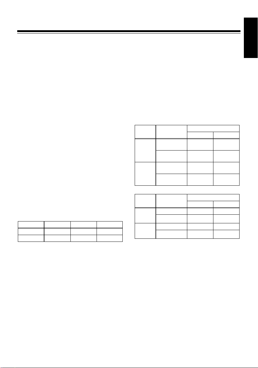
z A variable range for the volume can be
selected as follows.
However, the GAIN setting range covers
n
variations within
range covers variations within
200, and the BLACK setting
n
100,
respectively.
Volume variable range
MIN NORMAL MAX
GAIN 100 200 400
BLACK 50 100 200
1) GAIN volume
When the white balance is set using the PRE/
A/B button and the auto white balance (AWB)
executes, the lamp of the VR ACTIVE button
turns off, and the volume operation is
disabled.
When executing the AWB, the GAIN set value
will be “0” if the AWB OFFSET is set to OFF,
while the GAIN set value is retained if the
AWB OFFSET is set to ON.
When the relative value mode and the
absolute value mode are switched, the lamp
of the VR ACTIVE button turns off and the
volume operation is disabled. (The GAIN
value is unchanged.)
2) BLACK volume
This functions as an adjustment volume for
the flare (FLR) or the pedestal (PED) selected
in the BLACK-VR-CONTROL on the unit
menu.
If the auto black balance (ABB) is executed
while the pedestal is selected, the lamp of the
VR ACTIVE button turns off, and the volume
operation is disabled.
In this case, if the PEDESTAL OFFSET of the
camera recorder is set to OFF, the set value
will be cleared to 0.
Changes in the VR ACTIVE button when the ABB is executed
VR
setting
REL
(relative
value)
ABS
(absolute
value)
Changes in the volume set value when the ABB is executed
VR
setting
REL
(relative
value)
ABS
(absolute
value)
When the BLACK-VR-CONTROL item in the
unit menu changes, the lamp of the VR
ACTIVE button turns off, and the volume
operation is disabled.
If the BLACK-VR-CONTROL is set to “PED”,
the flare value can be changed in the unit
menu but it is impossible to change the
pedestal value.
BLACK-VR-
CONTROL
PED
FLR
PED
FLR
BLACK-VR-
CONTROL
PED Cleared to 0 Retains
FLR Retains Retains
PED Cleared to 0 Retains
FLR Retains Retains
PEDESTAL OFFSET
OFF ON
Turned off
(disabled)
Retains
state
Turned off
(disabled)
Retains
state
PEDESTAL OFFSET
OFF ON
Turned off
(disabled)
Retains
state
Turned off
(disabled)
Retains
state
ENGLISH
E-18

Basic operation (Continued)
3) M.PED volume
When the volume operation is enabled, the
unit operates in the absolute value mode
where the value is fixed in accordance with
the position of the volume. The value will be
“0” by clicking the center.
The variable amount is within a range
between the minimum value of –200 and the
maximum value of +200 with the center value
of 0.
Operation of the scene file
The unit has five sets of scene files and is
capable to storing the current settings as a scene
file or loading the stored settings.
It is also possible to store/call scene files using
the SD memory card. For details, refer to
“Saving/Loading of scene files onto the SD
memory card” (page 21).
1) Operation of the scene file
When the lamp of the RECORDER ENABLE
button is off, the scene files are operated
using the seven buttons on the top right side
of the unit.
Storing: Select a file number to store using
buttons 1 to 5 (blue letters). When
the button is pressed, the button
lamp will flash. If the SAVE (blue
letters) button is pressed in this
state, the SAVE button lamp will
also flash. To store the file, press
the SAVE button again. When the
store operation is finished, the
lamp of the button for the stored file
number turns on.
When the lamps for buttons 1 to 5
are flashing, press the button or
leave for 10 seconds or more to
release the selection.
Loading: Select a file number to load using
buttons 1 to 5 (blue letters). When
the button is pressed, the button
lamp will flash. If the LOAD button
is pressed in this state, the
selected file will load. At this time,
the lamp of the VR ACTIVE button
flashes, the operation mode of the
volume set in the unit menu is
ignored, and the unit is in the
relative value mode.
E-19

Basic operation (Continued)
<Notes>
z If a scene file is loaded while the volume
operation mode is set to the absolute value
mode, and then the VR ACTIVE button is
operated, the set value will correspond to
the volume angle and the loaded value will
be lost.
If you want to operate the volume from the
value loaded in the scene file, operate the
unit while the VR ACTIVE button lamp is
flashing or the operation modes of the
volumes for WHITE and BLACK are set to
the relative value mode before operating
the VR ACTIVE button.
z When a scene file is stored or loaded, the
button lamps for the file numbers of the files
stored or loaded and the LOAD button is
turned on. Press the LOAD button to turn
the button lamp off. When the camera
menu is opened or the scene file data is
loaded from the SD memory card, the
lamps for both of the File No. button and
the LOAD button turn off.
z When the camera menu is open,
operations of the scene file are disabled.
2) Items stored in the scene file
Refer to the Menu item Files for storing are
checked with a “Yes” Since the same operation
applies to storing on the SD memory card, when
a scene file stored in a specific unit of the remote
controller is used for another unit of the remote
controller, load data from the scene file from the
specific unit and store on an SD memory card,
and then read them out from the card and store
them in the scene file of the other unit.
<Note>
Do not turn off the power when a scene file is
being stored. Otherwise, data in the scene file
may be corupted.
<Reference>
It is possible to adjust the scene file setting of the
unit to the same state as the factory setting for
the camera recorder using the following
procedure.
However, the settings that cannot be set with the
unit cannot be set to the same state.
1 Set the settings for the camera recorder to
the factory settings. For details, refer to the
operation manual of the camera recorder.
2 Connect the unit to the camera recorder.
Settings for the unit will be imported from the
camera recorder.
3 Execute RCU-FACTORY on the SYSTEM
menu of the unit.
4 Store the settings on the unit to scene files 1
to 5 of the unit or an SD memory card.
Operation for recording
If the RECORDER ENABLE button is pressed to
switch to the recorder mode, operations of the
camera recorder are enabled.
If the REC INH button lamp is on, the REC S/S
button on the unit will be inhibited. To start and
stop recording, turn off the lamp of the REC INH
button by pressing the button, and start and stop
recording using the REC S/S button.
<Notes>
z While the REC INH button lamp is on, REC S/
S button operations are inhibited.
z If the RECORDER ENABLE button lamp turns
off by pressing the button while the recording
part is operated, the state of the recording
before turning off the lamp is retained and it is
possible to operate the scene file built into the
unit.
z It is possible to set whether the value adjusted
on the unit is retained on the camera recorder
or not, by using RC-DATA-SAVE in the FUNC
menu of the unit.
ENGLISH
E-20

Saving/Loading of scene files onto the SD memory card
It is possible to store up to 8 sets of settings for
the unit.
While data on the card are read or written, any
operation of the unit panel is inhibited. Insert the
SD memory card into the SD memory card slot
on the unit and operate the unit menu.
<Notes>
z Use an SD memory card with a capacity of 8
MB or more. The maximum capacity of an SD
card that can be used on the unit is 2 GB.
z The SD memory card must be formatted on
the unit.
Handling methods for the SD memory card
Ensure that the SD memory card is inserted or
ejected in the proper direction.
SD memory card
slot
When the SD memory card is used for the first
time, execute CARD CONFIG in SYSTEM on the
unit menu.
<Note>
While data are being stored on the SD memory
card or data are being loaded from the SD
memory card, do not remove the SD memory
card. Otherwise, data on the SD memory card
may be damaged.
To load data from the card
1 When “SYSTEM” is selected using the
SHUTTER/SYSTEM button, the indication
“CARD-RD” is displayed on the LCD panel
together with the value displayed under the
indication and the title next to the indication.
2 Select the file to read out by changing the
numerical value in the Rotary Encoder 1.
If there is no applicable file, the indication
“NO FILE” is displayed on the LCD panel.
3 Press the Rotary Encoder 3.
When the indication “READ NO?” is
displayed on the LCD panel, turn the Rotary
Encoder 3 to select “YES?” and press the
Rotary Encoder 3 again to start reading out
the data.
4 The read operation starts and the indication
“ACTIVE” is displayed on the LCD panel.
While the data are loaded, the SD memory
card access lamp is on.
SD memory card
access lamp
5 When the reading the data is finished, the
SD memory card access lamp turns off and
the indication “OK” is displayed on the LCD
panel.
<Note>
If the data cannot be read properly, the
indication “READ NG” is displayed on the
LCD panel. Execute the load operation
again. If the load operation is not executed
properly, replace the SD memory card with a
new one.
E-21

Saving/Loading of scene files onto the SD memory card
(Continued)
To write data on the card
1 Select “SYSTEM” using the SHUTTER/
SYSTEM button, and display the menu on
the second layer using the
4
button.
2 When the indication “CARD-WR” is
displayed on the LCD panel together with the
file number displayed under the indication,
turn the Rotary Encoder 1 to select the file.
<Note>
If the file already exists, the title is displayed
under the TITLE indication. Be careful and
do not overwrite the file.
3 When the cursor for entering the title is
displayed on the LCD panel, turn the Rotary
Encoder 3 to select the letters and turn the
Rotary Encoder 2 to move the cursor.
Up to eight letters can be entered. Once the
eighth letter is entered, the last letter will
flash.
4 When the Rotary Encoder 3 is pressed, the
indication “NO?” is displayed on the LCD
panel. Turn the Rotary Encoder to select the
indication “YES?” and start writing data by
pressing the Rotary Encoder 3 again.
5 When the writing operation starts, the SD
card access lamp is on and the indication
“ACTIVE” is displayed on the LCD panel.
6 When the writing of the data is finished, the
SD memory card access lamp turns off, and
the indication “OK” is displayed on the LCD
panel.
To delete files from the card
1 Select “SYSTEM” using the SHUTTER/
SYSTEM button, and display the menu on
the third layer using the
4
button.
2 When the indication “CARD-DEL” is
displayed on the LCD panel together with the
file number displayed under the indication,
turn the Rotary Encoder 1 to select the file to
be deleted.
3 When the Rotary Encoder 3 is pressed, the
indication “NO?” is displayed on the LCD
panel. Turn the Rotary Encoder 3 to select
the indication “YES?” and start deleting data
by pressing the Rotary Encoder 3 again.
4 When the deleting operation starts, the SD
card access lamp is on, and the indication
“ACTIVE” is displayed on the LCD panel.
5 When the deletion of the data is finished, the
SD memory card access lamp turns off, and
the indication “OK” is displayed on the LCD
panel.
Initialization of the card
1 Select “SYSTEM” using the SHUTTER/
SYSTEM button, and display the menu on
the fourth layer using the
The indication “EXEC” is displayed.
4
button.
2 When the Rotary Encoder 3 is pressed, the
indication “NO?” is displayed on the LCD
panel. Turn the Rotary Encoder 3 to select
the indication “YES?” and start the
initialization by pressing the Rotary Encoder
3 again.
ENGLISH
The following procedures are the same as
procedures
card.
4 and 5 for deleting files from the
E-22

Menu operation
Operations using the LCD panel
The menu can be adjusted using the Rotary
Encoders (1 to 3) after displaying the menu on
the LCD panel.
1 Press one of the following buttons: BLACK/
SHAD button, FLARE/MATRIX button,
GAMMA/DTL button, WHITE/SKINDTL
button, or KNEE/FUNC button to select an
item on the menu.
2 The indication will switch to the item under
the panel # the item on the panel # the
state before entering the menu mode # the
item under the panel step by step every time
the button is pressed.
The LED indicating the selected item is on
and the first layer of the menu for the
selected item is displayed on the LCD panel.
3 Move the layer on the menu using the
3
button or
looped.)
button. (Indications are not
4
4 Adjust the value of the sub-items on the
menu using the rotary encoder. The
numerical values are increased by turning
the rotary encoder clockwise and reduced by
turning it counterclockwise.
Depending on the layers, 1 to 3 sub-items
are displayed on the LCD panel.
(In some layers, it is necessary to press the
rotary encoder3)
5 When the camera menu is open, the menu
displayed on the LCD panel of the unit is
closed, “CAMERA MENU OPEN” is
displayed.
Operation of the camera recorder menu
With the unit, it is possible to set the menu of the
camera recorder by checking the monitor.
Use this feature to set any items that are not
included in the unit menu.
1 Connect the VIDEO OUT connector of the
unit to the monitor.
2 Press the MENU ON button for 3 seconds or
longer.
The menu of the camera recorder is
displayed on the monitor.
<Note>
When the lamp of the CHARA ON button is
off, the menu is not displayed on the monitor.
3 Operate the menu by operating the Rotary
Encoder 3 in the same way as the JOG dial
on the main unit of the camera recorder.
<Note>
Significant items such as frame frequency etc.,
cannot be changed from the unit. In this case,
these items can be changed from the camera
recorder.
For details such as menu items and setting
methods, refer to the operation manual of the
camera recorder.
Adjustment of functions on the unit
It is possible to adjust the sound heard when a
button on the unit is pressed and the brightness
of the LCD panel button by using the menu of the
unit. For details, refer to “SYSTEM” (page 31).
E-23

Menu item
Menu
The menu items on the unit may vary with the
camera recorder connected to the unit.
For the following menu items, the factory settings
for the unit only are set separately from the
camera recorder.
BLACK-VR-CONTROL, BLACK-VR-
MODE, and BLACK-VR-RANGE in
“BLACK”
GAIN-VR-MODE and GAIN-VR-RANGE in
“WHITE”
BUZZER, LCD CONTRAST, and SW
BRIGHT in “SYSTEM”
When the column of “Storage” in the menu table
is answered with “Yes”, the settings for the
relevant items can be stored on the unit or the
SD memory card as a scene file. For details,
refer to “Operation of the scene file” (page 19)
and “Saving/Loading of scene files onto the SD
memory card” (page 21).
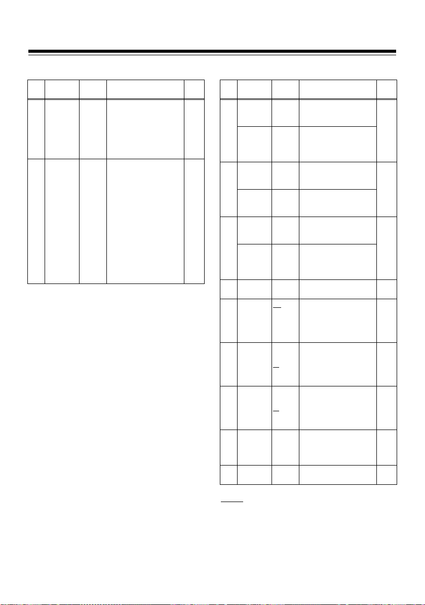
BLACK
Item
Variable
Contents description
range
–100
To set the pedestal for
:
Rch Yes
+100
–100
To set the pedestal for
:
Gch Yes
+100
–100
To set the pedestal for
:
Bch Yes
+100
FLR
To select the items to be
PED
adjusted using the
BLACK volume
FLR: FLARE
PED: PEDESTAL
ABS
To select whether the
BLACK volume of the
REL
RGB is operated using
the absolute value or
the relative value
ABS: Absolute value
REL: Relative value
MIN
To switch the variable
NORM
range of the BLACK
MAX
volume of RGB
MIN:
NORM:
MAX:
Storage
Yes
Yes
n
25
n
50
n
100
Yes
Layer
1
RPED
GPED
BPED
2
BLACK-VRCONTROL
BLACK-VR-
3
MODE
4
BLACK-VRRANGE
<Note>
When “PED” is selected in the BLACK-VR-CONTROL
and the lamp of the VR ACTIVE button is on or “ABS”
(absolute value) is selected in the BLACK-VR-MODE
item, it is impossible to adjust the PRED/GPEG/BPEG
items using the rotary encoder. Adjust these items using
the BLACK volume.
ENGLISH
is the factory setting mode.
E-24

Menu item (Continued)
FLARE
Item
Variable
Contents description
range
–100
To set the flare for Rch
:
+100
–100
To set the flare for Gch
:
+100
–100
To set the flare for Bch
:
+100
To set ON/OFF of the
flare correction
Storage
Yes
Yes
Yes
Yes
Layer
1
RFLAR
GFLAR
BFLAR
2
FLARCORRECTONOFF
<Note>
When the BLACK volume is assigned for flare
adjustment, it must be set in BLACK-VR-CONTROL,
BLACK-VR-MODE, and BLACK-VR-RANGE. When
“FLR” is selected in the BLACK-VR-CONTROL item, the
flare can be adjusted by using the BLACK volume.
Switching between the absolute value mode and the
relative value mode of the volume can be set in the
BLACK-VR-MODE item, while switching of the variable
range can be set in the BLACK-VR-RANGE item. When
the absolute value is selected in the BLACK-VR-MODE
item or the lamp of the VR-ACTIVE button is turned on,
R FLAR/G FLAR/B FLAR items cannot be adjusted
using the rotary encoder. They must be adjusted with
the BLACK volume.
GAMMA
Item
Variable
Contents description
range
–15
To set the gamma for
:
Rch Yes
+15
0.30
To set the master
:
gamma Yes
0.75
–15
To set the gamma for
:
Bch Yes
+15
To select the gamma
F-LIKE1
F-LIKE2
F-LIKE3
To set ON/OFF of the
gamma correction
Storage
Yes
Yes
Layer
1
RGAM
MGAM
BGAM
2
GAMMAMODE-SELHDSD
3
GAMMACORRECTONOFF
WHITE
Item
Variable
Contents description
range
–200
To set the Rch gain
:
+200
–200
To set the Bch gain
:
+200
ON
To select whether the
OFF
filter has data for the
AWB memory (Ach,
Bch) or not, for the
respective filters
independently
ON: Data are held in
two memory
locations (Ach,
Bch) regardless
of the filter.
OFF: The respective
filters hold data.
OFF
To turn on the shockFAST
less AWB (FAST/
NORMAL
NORMAL/SLOW1/
SLOW1
SLOW2/SLOW3)
SLOW2
SLOW3
25%
To switch the AWB
50%
detection area Yes
90%
ABS
To select whether the
REL
GAIN volumes for R
and B are operated
using the absolute
value or the relative
value
ABS: Absolute value
REL: Relative value
MIN
To switch the variable
NORM
range of the GAIN
volumes for R and B
MAX
MIN:
NORM:
MAX:
n
n
n
50
100
200
Storage
Layer
1
RGAIN
BGAIN
2
FILTER-INH
SKLS-AWB
3
AWBARE A
4
GAIN-VRMODE
GAIN-VR-
5
RANGE
<Note>
When the absolute value is selected in the GAIN-VRMODE item, or the lamp of the VR ACTIVE button is
turned on, the R GAIN/G GAIN items cannot be
adjusted using the rotary encoder. They must be
adjusted using the GAIN volume.
is the factory setting mode.
Yes
Yes
Yes
Yes
Yes
Yes
E-25

Menu item (Continued)
WHITE (Continued)
Item
Variable
Contents description
range
2300k
To set the color
:
temperature in the AWB
8000k
PRE
MEM
To set the position of
the WHITE BAL switch
and the assignment of
Ach
MEM: This assigns the
2300k
To set the position of
:
the WHITE BAL switch
8000k
and the color
temperature in case of
Ach
The step varies with the
camera conditions.
ON: Even if the AWB is
OFF: When the AWB is
memory value
when the AWB is
executed.
executed, the set
value for the GAIN
OFFSET of the
AWB-A will not be
reset.
executed, the set
value for the GAIN
OFFSET of the
AWB-A will be
reset.
Layer
6
COLRTEMP-PRE
7
AWB-A
TEMP-A
AWB-A -
8
GAIN-OFSTONOFF
Storage
No
Yes
No
Yes
Layer
9
AWB-B
TEMP-B
AWB-B-
10
GAIN-OFSTONOFF
Item
Variable
Contents description
range
MEM
To set the position of
the WHITE BAL switch
and the assignment of
Bch
MEM: This assigns the
2300k
To set the position of
:
the WHITE BAL switch
8000k
and the color
temperature in case of
Bch
The step varies with the
camera conditions.
ON: Even if the AWB is
OFF: When the AWB is
memory value
when the AWB is
executed.
executed, the set
value for the GAIN
OFFSET of the
AWB-B will not be
reset.
executed, the set
value for the GAIN
OFFSET of the
AWB-B will be
reset.
Storage
Yes
No
Yes
ENGLISH
E-26

Menu item (Continued)
KNEE SHUTTER
Item
Variable
Contents description
range
ON
To set the mode when
OFF
the AUTO KNEE switch
is off
ON: MANUAL KNEE
OFF: KNEE OFF
70.0%
To set the position of
:
the MANUAL KNEE
107.0%
POINT by 0.5% step
00
To set the tilt angle of
:
the MANUAL KNEE Yes
99
ON
To set ON/OFF of the
OFF
WHITE CLIP function
90%
To set the WHITE CLIP
:
LEVEL
109%
80%
To set the position of
:
the AUTO KNEE POINT
107%
by 1% ste p
100
To set the AUTO KNEE
:
LEVEL
109
1
To set the AUTO KNEE
:
response speed
8
Storage
Yes
Yes
Yes
Yes
Layer
1
Item
MODE
SPED
ACTION
Layer
1
2
3
4
M-KNEE
MKNPNT
MKNSLP
WCLIP
WCLIPLVL
AKNP
AKLV
AKRESP
Variable
Contents description
range
FIX
To select whether the
S.S
shutter setting for
SHUTTER ON is set to
the fixed mode or the
synchro-scan mode
FIX: Fixed shutter
S.S: Syncro-scan
1/60
To select the shutter
1/100
speed
1/120
The selected speed
1/250
type (for the fixed
1/1000
shutter, for the synchro1/2000
scan) varies with the
HALF
mode.
ON
To display conditions of
OFF
the shutter
(Display only)
Storage
Yes
Yes
No
E-27

Menu item (Continued)
SHAD
Item
Variable
Contents description
range
ON
To select the black
OFF
shading ON/OFF
EXEC
To activate the auto
black shading
adjustment
ON
To select the white
OFF
shading ON/OFF
–255
To adjust the R-H-SAW
:
white shading
+255
Every NORM and
EXTENDER has
respective values.
–255
To adjust the R-H-PARA
:
white shading
+255
–255
To adjust the R-V-SAW
:
white shading
+255
–255
To adjust the R-V-PARA
:
white shading
+255
–255
To adjust the G-H-SAW
:
white shading
+255
–255
To adjust the G-H-PARA
:
white shading
+255
–255
To adjust the G-V-SAW
:
white shading
+255
–255
To adjust the G-V-PARA
:
white shading
+255
–255
To adjust the B-H-SAW
:
white shading
+255
–255
To adjust the B-H-PARA
:
white shading
+255
–255
To adjust the B-V-SAW
:
white shading
+255
–255
To adjust the B-V-PARA
:
white shading
+255
Storage
Yes
No
Yes
Yes
Yes
Yes
Yes
Yes
Yes
Layer
1
B-SHD
DETECT
2
W-SHD
HSAW
3
(W-R)
HPAR
(W-R)
4
VSAW
(W-R)
VPAR
(W-R)
5
HSAW
(W-G)
HPAR
(W-G)
6
VSAW
(W-G)
VPAR
(W-G)
7
HSAW
(W-B)
HPAR
(W-B)
8
VSAW
(W-B)
VPAR
(W-B)
<Note>
For the adjustment of the shading, the adjusted setting
on the unit will be retained in the main unit of the camera
recorder regardless of the ON/OFF setting on the RCDATA-SAVE item.
MATRIX
Layer
Item
1
TA BL
C-CORCT
2
R-G
R-B
3
G-R
G-B
4
B-R
B-G
5
C-COR
SATU
PHASE
Variable
Contents description
range
A
To select the table for
B
the matrix color
correction in case of the
MATRIX ON and one to
be set on the unit.
ON
To select ON/OFF for
OFF
the 12-axis color
correction
–63
To adjust the matrix
:
color of R-G
+63
It will be switched using
the TABL A/B.
–63
To adjust the matrix
:
color of R-B
+63
–63
To adjust the matrix
:
color of G-R
+63
–63
To adjust the matrix
:
color of G-B
+63
–63
To adjust the matrix
:
color of B-R
+63
–63
To adjust the matrix
:
color of B-G
+63
R
To select the color
R-Mg
correction axis to be
Mg
adjusted in the 12-axis
Mg-B
color correction
B
B-Cy
Cy
Cy-G
G
G-YI
YI
YI-R
–63
To adjust the saturation
:
of the color correction
+63
axis selected in the C-
COR.
–63
To adjust the color
:
phase of the color
+63
correction axis selected
in the C-COR.
Storage
Yes
Yes
Yes
Yes
Yes
ENGLISH
E-28

Menu item (Continued)
DTL SKIN DTL
Item
Variable
Contents description
range
–31
To set the level of the
:
master detail (H and V)
+31
0
To set the H.DTL
:
LEVEL
63
0
To set the V.DTL LEVEL
:
31
OFF
To set detailed noise
0
elimination level
:
5
0
To set the H.DTL FREQ
:
31
0
To set the LEVEL
:
DEPEND
5
OFF
To set the details of the
0
high brightness part
:
5
–31
To change the level in
:
the + direction of the
+31
H.DTL
–31
To change the level in
:
the – (down) direction of
+31
the H.DTL
0
To change the clip in the
:
+ direction of the DTL
63
signals
R+G
To set the signal source
G+B
of the DTL signal
2G+R+B
components
3G+R
R
G
Storage
Yes
Yes
Yes
Yes
Layer
1
2
3
4
Item
S DTL
OUTPUT
SZEB
TA BL
SCORG
YMAX
YMIN
Layer
1
2
3
4
MDTL
HDTL
VDTL
CORG
FREQ
LDP
K-AP
+GAIN
–GAIN
CLIP
SOURCE
Variable
Contents description
range
OFF
To select the skin tone
A
table that enables skin
B
tone details
AB
OFF: To select OFF of
A: To put DTL in the
B: To put DTL in the
AB: To put DTL in the
MONI
To select the output that
VIDEO
adds SKINZEBRA
ON
To select ON/OFF for
OFF
SKIN ZEBRA against
the output selected in
OUTPUT
The ZEBRA will be
attached to the color of
the table set in
DETECT.
A
To select the table for
B
setting SKIN TONE to
be adjusted using the
unit
0
To set the effects of
:
SKIN TONE DTL
7
scoring
0
To set the maximum
:
value of the brightness
255
signals enabling SKIN
TONE
0
To set the minimum
:
value of the brightness
255
signals enabling SKIN
TONE
the skin color
DTL
SKINTONE
setting set in
Table A
SKINTONE
setting set in
Table B
SKINTONE
setting set in
Tables A and B
Storage
Yes
Yes
Yes
Yes
E-29

Menu item (Continued)
SKIN DTL (Continued)
Item
Variable
Contents description
range
0
To set the center
:
position on the I-axis (to
255
set the area where
SKIN TONE is effective)
0
To set the width of the
:
area where SKIN TONE
255
on the I-axis with the
center position at I
CENT is effective
0
To set the width of the
:
area where SKIN TONE
255
on the Q-axis with the
center position at I
CENT is effective
–128
To set the phase of the
:
area where SKIN TONE
+127
having a standard on
the Q-axis is effective
EXEC
This will be used for
obtaining the color
phase as the target for
SKIN TONE DTL
Layer
5
6
7
ICENT
IWIDTH
QWIDTH
QPHASE
SKIN-GET
Storage
Yes
Yes
No
FUNC
Layer
1
IRISLVL
PEAK/AVE
IRIS-
2
WINDOW
3
IRISGAIN
GAINVAL
4
USER-SW
SELECT
Item
Variable
Contents description
range
0
To set the target value
:
of the auto iris
100
0
To determine the
:
accounting ratio of the
100
peak against the
standard of the auto iris
NORM1
To select the auto iris
NORM2
detection window
NORM1
CENTER
NORM2
CENTR
CAM
To select whether the
LENS
iris gain is adjusted on
the camera recorder or
the lens
1
To set the IRIS GAIN
:
adjustment value on the
20
camera recorder
USW-M
To select the USER
USW-1
switch where functions
USW-2
will be changed
INH
To select the function to
S/GAIN
be assigned to the
DS.GAIN
USER button selected
LINE MIX
in the USER-SW item
S.IRIS
<Note>
I.OVR
When the unit is
S.BLK
connected to the
B.GAMMA
camera recorder, the
AUDIO CH1
“I.OVR” operation is
AUDIO CH2
disabled.
REC SW
Y GET
RET SW
PRE REC
DRS
: Center of the
screen
: Bottom side of
the screen
: Spots at the
center of the
screen
Storage
Yes
Yes
Yes
Yes
ENGLISH
E-30
Menu item (Continued)
FUNC (Continued)
Item
Variable
range
–1
OFF
1
2
3
Layer
5
BLKGAMMA–3–2
6
RC-DATASAVEONOFF
Contents description
To set the gamma curve
for dark portions
To select whether the
value adjusted in the
unit will be retained in
the main unit of the
camera recorder or not,
when the unit is
removed from the
camera recorder
When this is set to OFF
and the unit is removed,
the settings for the
camera recorder will
return to the state
before connecting the
unit.
Storage
Yes
Yes
SYSTEM
Layer
Item
1
CARDREAD1 :
TITLE
CARD-
2
WRITE1 :
TITLE
CARD-
3
DELETE1 :
TITLE
CARD-
4
CONFIG
BUZZER
5
LCD
6
CONTRAST0 :
7
SW BRIGHT
8
RCUFACTRY
VERSION
9
Variable
Contents description
range
To select the file
number to be read out
8
¢¢¢¢¢
To read out the title
¢¢¢
applied to the data of
the file to be read out,
and display it
To select the file
number to be written
8
¢¢¢¢¢
To enter the title applied
¢¢¢
to the data of the file to
be written
To select the file
number to be deleted
8
¢¢¢¢¢
To read the title applied
¢¢¢
to the data of the file to
be deleted, and display
it
To configure the card
ON
To select whether the
OFF
buzzer is turned on
when the switch for the
lamp to turn on is
pressed
To adjust the contrast of
the LCD panel
10
:
15
0
To adjust the brightness
:
of the lamp for the
10
switch No
:
15
To return the volume
variable range of the
unit to the factory
settings
To display the version of
the software for the unit
Storage
No
No
No
No
No
No
No
No
E-31
is the factory setting

Connection cable
A 10 m connection cable is attached to the unit. To extend the cable, use the optional dedicated cable.
If several 10 m cables are connected in tandem, the power supply may be unstable due to voltage
drops etc.
In an emergency, apply a higher voltage within a range from 11 V to 17 V for the power supply of DC 12
V to the camera recorder. If the input voltage to the unit is 8 V or less, operation becomes unstable.
Refer to the following. A twisted-pair cable must be used for the control line of the 10-pin cable.
Attenuation of the coaxial cable must be set to around –6 dB at maximum in 10 MHz.
ENGLISH
Camera recorder side
HR10A-10P-10P (Hirose Electric)
CAM DATA (H)
CAM DATA (C)
CAM CONT (H)
CAM CONT (L)
ECU_ON
Video output
GND (Video)
Standby
+12 V (IN)
GND
Connector GND
1
2
3
4
5
6
7
8
9
10
Twisted pair
Twisted pair
1.5C - 2V
3
h
or less
h
or less
3
Controller side
HR10A-10P10S (Hirose Electric)
CAM DATA (H)
1
CAM DATA (C)
2
CAM CONT (H)
3
CAM CONT (L)
4
ECU_ON
5
Video input
6
GND (Video)
7
Standby
8
+12 V (IN)
9
GND
10
Connector GND
Confirmation of software version
The software version for this unit can be confirmed in “VERSION” under SYSTEM in the unit menu.
Confirm for questions.
E-32

Specifications
Power supply: DC 12 V
Power consumption: 6 W
indicates safety items.
External dimensions (W a H a D)
185 mm a 131 mm a 60 mm
(7-5/16 inches a 5-3/16 inches a
2-5/8 inches)
Weight
1.3 kg (2.87 lb)
Operating temperature
0 °C to +40 °C (32 °F to 104 °F)
Storage temperature
–20 °C to +60 °C (–4 °F to 140 °F)
Maximum cable length
50 m
[Input/Output]
CAMERA
10-pin multi-connector a 1
MONITOR
BNC a 1, 1 VP-P (for menu setting)
Please note that specifications and appearance are
subject to change, for improvement purpose,
without notice.
E-33

Information on Disposal for Users of Waste Electrical & Electronic Equipment (private
households)
This symbol on the products and/or accompanying documents means that used electrical
and electronic products should not be mixed with general household waste.
For proper treatment, recovery and recycling, please take these products to designated
collection points,where they will be accepted on a free of charge basis. Alternatively, in
some countries you may be able to return your products to your local retailer upon the
purchase of an equivalent new product.
Disposing of this product correctly will help to save valuable resources and prevent any
potential negative effects on human health and the environment which could otherwise
arise from inappropriate waste handling. Please contact your local authority for further
details of your nearest designated collection point.
Penalties may be applicable for incorrect disposal of this waste, in accordance with
national legislation.
For business users in the European Union
If you wish to discard electrical and electronic equipment, please contact your dealer or supplier for
further information.
Information on Disposal in other Countries outside the European Union
This symbol is only valid in the European Union.
If you wish to discard this product, please contact your local authorities or dealer and ask for the correct
method of disposal.
ENGLISH
E-34

PANASONIC BROADCAST & TELEVISION SYSTEMS COMPANY
UNIT COMPANY OF PANASONIC CORPORATION OF NORTH AMERICA
Executive Office:
One Panasonic Way 4E-7, Secaucus, NJ 07094 (201) 348-7000
EASTERN ZONE:
One Panasonic Way 4E-7, Secaucus, NJ 07094 (201) 348-7196
Southeast Region: (201) 348-7162
WESTERN ZONE:
3330 Cahuenga Blvd W., Los Angeles, CA 90068 (323) 436-3500
Government Marketing Department:
One Panasonic Way 2E-10, Secaucus, NJ 07094 (201) 348-7587
Broadcast PARTS INFORMATION & ORDERING:
9:00 a.m. – 5:00 p.m. (EST) (800) 334-4881/24 Hr. Fax (800) 334-4880
Emergency after hour parts orders (800) 334-4881
TECHNICAL SUPPORT:
Emergency 24 Hour Service (800) 222-0741
Panasonic Canada Inc.
5770 Ambler Drive, Mississauga, Ontario L4W 2T3 (905) 624-5010
Panasonic de Mexico S.A. de C.V.
Av angel Urraza Num. 1209 Col. de Valle 03100 Mexico, D.F. (52) 1 951 2127
Panasonic Puerto Rico Inc.
San Gabriel Industrial Park, 65th Infantry Ave., Km. 9.5, Carolina, Puerto Rico 00630 (787) 750-4300
Professional & Broadcast IT Systems Business Unit Europe
Panasonic Marketing Europe GmbH
Hagenauer Str. 43, 65203 Wiesbaden-Biebrich Deutschland Tel: 49-611-235-481
松下电器产业株式会社
Web Site: http://panasonic.net
松下電器産業株式会社 システム事業グループ
〒 571-8503 大阪府門真市松葉町2番15号 i(06)6901ー 1161
C 2006 Matsushita Electric Industrial Co., Ltd All Rights Reserved
G
 Loading...