

Page 1
Thank you for purchasing this product.
Before operating this product, please read the instructions carefully and save this manual for future use.
Operating Instructions
Digital Triax Camera Adapter
Model No. AJ-
P
EN
F0903H0
@
3
Printed in Japan
VQT0F80
EN
Page 2
2
Safety precautions
Indicates safety information.
General
CAUTION:
TO REDUCE THE RISK OF FIRE OR SHOCK
HAZARD AND ANNOYING INTERFERENCE,
USE THE RECOMMENDED ACCESSORIES
ONLY.
CAUTION:
TO REDUCE THE RISK OF FIRE OR SHOCK
HAZARD, REFER CHANGE OF SWITCH
SETTING INSIDE THE UNIT TO QUALIFIED
SERVICE PERSONNEL.
Model AJ-CA901P
CAUTION
RISK OF ELECTRIC SHOCK
DO NOT OPEN
CAUTION: TO REDUCE THE RISK OF ELECTRIC SHOCK,
DO NOT REMOVE COVER (OR BACK).
NO USER SERVICEABLE PARTS INSIDE.
REFER TO SERVICING TO QUALIFIED SERVICE PERSONNEL.
The lightning flash with arrowhead symbol,
within an equilateral triangle, is intended to
alert the user to the presence of uninsulated
“dangerous voltage” within the product’s
enclosure that may be of sufficient magnitude
to constitute a risk of electric shock to
persons.
The exclamation point within an equilateral
triangle is intended to alert the user to the
presence of important operating and
maintenance (service) instructions in the
literature accompanying the appliance.
FCC Note:
This device complies with Part 15 of the FCC Rules.
To assure continued compliance follow the attached
installation instructions and do not make any
unauthorized modifications.
This equipment has been tested and found to comply
with the limits for a class A digital device, pursuant to
Part 15 of the FCC Rules. These limits are designed
to provide reasonable protection against harmful
interference when the equipment is operated in a
commercial environment. This equipment generates,
uses, and can radiate radio frequency energy and, if
not installed and used in accordance with the
instruction manual, may cause harmful interference to
radio communications. Operation of this equipment in
a residential area is likely to cause harmful
interference in which case the user will be required to
correct the interference at his own expense.
WARNING:
•
TO REDUCE THE RISK OF FIRE OR
SHOCK HAZARD, DO NOT EXPOSE THIS
EQUIPMENT TO RAIN OR MOISTURE.
• TO REDUCE THE RISK OF FIRE OR SHOCK
HAZARD, KEEP THIS EQUIPMENT AWAY
FROM ALL LIQUIDS—USE AND STORE
ONLY IN LOCATIONS WHICH ARE NOT
EXPOSED TO THE RISK OF DRIPPING OR
SPLASHING LIQUIDS, AND DO NOT PLACE
ANY LIQUID CONTAINERS ON TOP OF THE
EQUIPMENT.
CAUTION:
Do not install or place this unit in a bookcase,
built-in cabinet or any other confined space in
order to maintain adequate ventilation. Ensure
that curtains and any other materials do not
obstruct the ventilation to prevent risk of
electric shock or fire hazard due to
overheating.
∫∫
DO NOT REMOVE PANEL COVER BY
UNSCREWING.
To reduce the risk of electric shock, do not remove
cover. No user serviceable parts inside.
Refer servicing to qualified service personnel.
Model AJ-CA901EN
Page 3

3
Safety precautions..................................................................... 2
Features .................................................................................... 3
Installation ................................................................................. 4
Parts and their functions............................................................ 5
Rear panel ..................................................................................................5
Left side ......................................................................................................6
Right side....................................................................................................6
Connectors and signals............................................................. 7
Selecting the intercom microphone ........................................... 8
Specifications ............................................................................ 9
Contents
The unit has the following features.
≥ It enables high picture quality transmission by means of non-compressed wide-band 360 Mbps serial component signals.
≥ It uses a tri-axial cable.
≥ It enables a DVCPRO camera recorder to be operated as a system camera.
≥ It enables the transmission of the signals of two audio channels.
≥ It enables RET 1CH and PROMPT 1CH transmission.
≥ Its TRIAX connector area can be rotated for easy operation.
≥ It comes with RET and PROMPT output connectors (BNC).
≥ It comes with a DC 12 V output jack.
Features
Thank you very much for purchasing this AJ-CA901 Camera Adapter (referred to throughout these instructions as “the unit”).
The unit is installed in a DVCPRO50 AJ-SDX900 camera recorder and used together with the AJ-BS901 base station to
configure a transmission system which uses a tri-axial cable to enable the camera recorder to be operated as a system
camera.
Use of non-compressed wide-band 360 Mbps serial component signals makes high picture quality transmission possible so
that the high picture quality of the images shot by the DVCPRO camera recorder are transmitted with their high picture quality
kept intact.
This serves to expand the range of the DVCPRO camera recorder’s operating formats.
Note:
≥≥
When the unit is connected, external input signals cannot be recorded on tape inside the camera
recorder.“CAM” must be selected as the REC SIGNAL setting on the SYSTEM SETTING menu of the
camera recorder.
≥≥
When using an external power supply (DC 12 V) for the unit, always turn the main power switch of
the base station (AJ-BS901) ON before turning the power switch of the camera recorder ON.
Page 4

4
Installation
D
C
IN
CH 1
CH 2
AUDIO IN
DC O
UT 12V 1A
M
I
C
+
4
8
V
L
IN
E
A
U
D
I
O
O
U
T
V
ID
E
O
O
U
T
E
C
U
M
I
C
+
4
8
V
L
I
N
E
A
J
-
C
a
m
e
r
a
A
d
a
p
t
e
r
M
IC
L
EV
E
L
IN
C
O
M
PG
M
ON
OFF
ON
OFF
PTT
D
IG
IT
A
L
T
R
IA
X
I
M
P
O
R
T
A
N
T
N
O
T
T
O
B
E
U
S
E
D
A
S
A
C
H
A
R
G
E
A
D
A
P
T
E
R
OFF
ON
MIC
LEVEL
INCOM
PGM
O
N
O
F
O
N
P
2.
As shown in the figure on the left, align the spacer on the
back of the camera recorder with the guide in the unit, and
push the unit in the direction of the arrow until it clicks into
place.
1.
Make sure that the coin screw used to secure the AJ-CA901
connectors is unscrewed (The screw will be completely
disengaged from the thread.). Mounting the AJ-CA901 with
the screw in the closed position could damage the
connectors.
3.
Screw the coin screw to the closed position while pressing
down on it.
Coin screw
Follow the steps below to attach the unit to the camera recorder.
<Note>
Depending on the version of the software being used with the camera recorder, it may be necessary to update it, in which case you
should consult your dealer.
<Note>
After the AJ-CA901 has been attached to the camera recorder, the camera recorder cannot be operated independently unless it has
been connected as a system to the AJ-BS901 Base Station. When using the camera recorder unit independently, always remove
the AJ-CA901 before proceeding.
Page 5
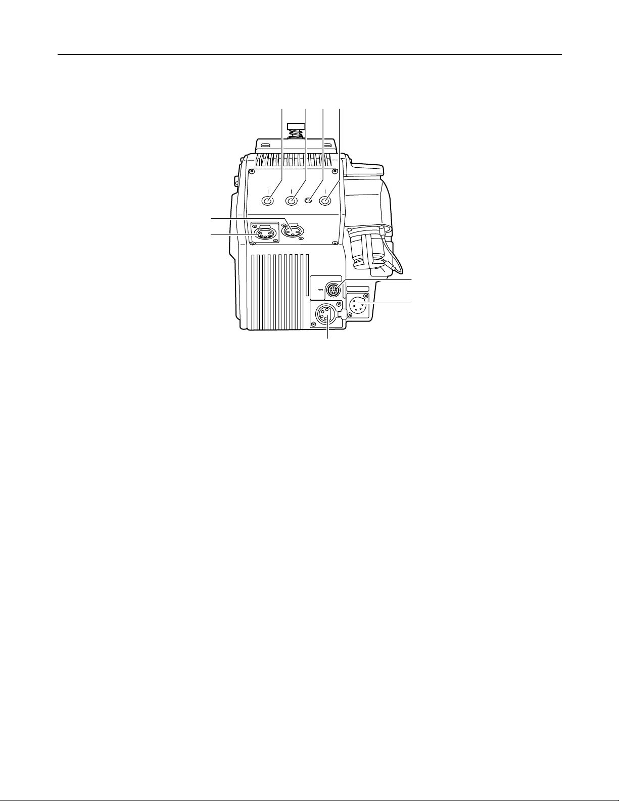
5
RET 1 RET 2
INCOM
PUSH
PUSH
PGM OUT
CALL
RET SW
DC 12V IN
DC OUT
1
2
4
5
6
7
8
9
500mA
12V
3
Parts and their functions
1
Return select button (RET1)
This button is used to select the return signal generated when the return switch is pressed. This button selects
RET1.
2
Return select button (RET2)
This button is used to select the return signal generated when the return switch is pressed. This button selects
RET2.
3
Call lamp
This lights when t
he camera recorder has been called up by the base station (AJ-BS901) or when R TALLY
has been set to
ON.
4
CALL button
This button is used to call the base station (AJ-BS901) from the camera adapter. Pressing the CALL button
causes the CALL lamp on the AJ-BS901 to light.
5
Return switch jack (RET SW)
This jack connects to RET SW BOX. Supported functions are RET1 and RET2 selection as well as intercom
PTT (push to talk) and CALL.
Rear panel
7
DC OUT (DC power supply output) jack
This is a DC 12 V output jack. A current up to 500 mA can be output from this jack.
6
DC 12V IN (external power supply input) jack
When the unit is operated using an external power supply, the AJ-B95 AC adapter (sold separately) connects
to this jack. It is also possible to connect an external battery to this jack.
When connection is made to this jack, the external power supply is selected automatically.
<Note>
When the AJ-CA901 camera adapter (this unit) has been installed, the camera recorder unit is set to EXT DC
IN mode. When the battery warning is displayed, select the type of battery for detecting the remaining charge
in EXT DC IN SELECT of BATTERY/TAPE in the VTR menu of the camera recorder.
8
Intercom connector
This connecter is used to connect to an intercom system via the AJ-BS901 for two-way voice connections.
9
PGM OUT connector
This is the PGM audio output connector.
Page 6

6
Parts and their functions
1
Microphone intercom switch (MIC)
Used to switch the intercom line between the ON, OFF, and
PTT settings. (PTT: Audio transmission continues as long as
the switch is held down.)
2
Intercom level knob (LEVEL)
This knob is used to adjust the intercom reception volume
level.
3
Program level knob (PGM)
This knob is used to adjust the intercom PGM volume level.
4
Program line switch
This switch controls the program line multiplexed on the
intercom line. It has two positions: ON and OFF.
AJ-Camera
Adapter
MIC LEVEL
INCOM
PGM
ON
OFF
ON
OFF
PTT
DIGITAL TRIAX
1
2
34
Left side
3
Triax connector
This connector is used to connect to the base station (AJBS901) using a triax cable.
1
Prompter video output (PROMPT OUT)
The prompter video signal input to the base station (AJBS901) is output from this jack.
2
Return video output (RET OUT)
The return video signal (either RET1 or RET2) input to the
base station (AJ-BS901) is output from this jack.
RET-1 or RET-2 is selected by operating the return select
button (see page 5).
PROMPT
OUT
RET OUT
1
2
3
Right side
Page 7

7
Connectors and signals
PGM OUT
1 GND
2 PGM (H)
3 PGM (C)
Manufacturer part number: HA16RM-3P
(Hirose Denki)
2
3
1
RET SW
A RET1
B MIC ON/OFF
C RET2
D TALLY
E GND
F +12V-OUT
G CALL
H GND
Manufacturer part number: PRC07-R8F
(Tajimi Musen)
A
B
C
D
E
F
G
H
5
4
3
2
1
INCOM
1 GND
2 INCOM TALK (H)
3 GND
4 INCOM RECEIVE (H)
5 PGM / RECEIVE (C)
DC 12V OUT
1 GND
2
3
4 +12V
Matsushita part number: VJS3290
Manufacturer part number: HA16PRH-5S
(Hirose Denki)
Manufacturer part number: HA16PRH-4S
(Hirose Denki)
4
3
2
1
DC IN
1 GND
2
3
4 +12V
Matsushita part number: VJP3429
Manufacturer part number:
HA16RX-4P(SW1)
(Hirose Denki)
1
2
3
4
SW
Page 8

8
Selecting the intercom microphone
AJ-Camera
Adapter
MIC LEVEL
INCOM
PGM
ON
OFF
ON
OFF
PTT
DIGITAL TRIAX
1.
Remove the four screws from the side of the AJ-CA901 shown
in the figure, and remove the side panel.
2.
Refer to the figure on the left, and set the switch inside the
side panel which was removed.
Screws (4)
Dynamic
microphone
Carbon
microphone
Switch
Proceed as follows to select the dynamic microphone or carbon microphone as the intercom microphone. Before proceeding with
the work, be absolutely sure to turn off the power.
CAUTION:
These servicing instructions are for use by
qualified service personnel only. To reduce the
risk of electric shock do not perform any
servicing other than that contained in the
operating instructions unless you are qualified
to do so.
Page 9

External dimensions (W a H a D): 6-3/16 a 7-9/16 a 6-13/16-inches
(156.5 a 191.5 a 173 (mm))
Weight: 4.84 lbs (2.2 kg)
Operating temperature range: 32°F to 104°F (0°C to 40°C)
Storage temperature range: –4°F to 140°F (–20°C to +60°C)
Operating humidity: 10 to 85% (relative humidity)
Transfer block
Signal transfer rate: 360 Mbps (AJ-CA901 to AJ-BS901)
Transfer distance: 300 m with diameter 8.6 mm cable (Fujikura)
500 m with diameter 14.5 mm cable (Fujikura)
Video transfer rate: Signals from camera to base station:
Y signal: 18 MHz sampling rate, 10-bit
R-Y signal: 9 MHz sampling rate, 10-bit
B-Y signal: 9 MHz sampling rate, 10-bit
Signals from base station to camera:
RET signal: FM modulation
Prompt signal: FM modulation
Audio transfer rate: Signals from camera to base station:
46.875 kHz sampling rate, 16-bit
Signals from base station to camera:
11.71875 kHz sampling rate, 16-bit
Intercom
Microphone selection: Switchable between dynamic microphone and carbon microphone
I/O level: 4-line/2-line: 0 dBm (600 Ω, balanced)
RTS: 1 Vp-p (200 Ω)
PGM: 0 dB (600 Ω, balanced)
Format: Selectable between 4-line, 2-line, and RTS
Lines: Base station to camera: 2 lines (ENG, PGM)
Camera to base station: 1 line (ENG)
S/N ratio: 50 dB or more (base station to camera) (camera to base station)
Distortion: 1.0% or less
Frequency range: 100 Hz to 10 kHz (± 3 dB) (camera to base station)
100 Hz to 5 kHz (± 3 dB) (base station to camera)
Dynamic range: 12 dB or more
Video system
Teleprompt output (PROMPT): 1 Vp-p (1 Vp-p input to AJ-BS901)
RET output: 1 Vp-p (1 Vp-p input to AJ-BS901)
Input connectors
Intercom connector: XLR 5-pin
External DC power supply input connector:
XLR 4-pin
RET SW connector: 8-pin
Output connectors
Teleprompt (PROMPT) output connector:
BNC VBS, 1 Vp-p, 75 Ω
RET signal output connector: BNC VBS, 1 Vp-p, 75 Ω
External power supply output connector:
XLR 4-pin
PGM audio output connector: XLR 3-pin
Weight and dimensions shown are approximate.
Specifications are subject to change without notice.
9
Specifications
Input: 100 V DC (supplied by AJ-BS901)
12V DC IN (11.5 V to 17.0 V DC)
Power consumption: BS Input 100 V : 450 mA
EXT Input 12 V : 3.2 A
Indicates safety information.
Page 10

PANASONIC BROADCAST & TELEVISION SYSTEMS COMPANY
UNIT COMPANY OF MATSUSHITA ELECTRIC CORPORATION OF AMERICA
Executive Office:
One Panasonic Way 4E-7, Secaucus, NJ 07094 (201) 348-7000
EASTERN ZONE:
One Panasonic Way 4E-7, Secaucus, NJ 07094 (201) 348-7621
Southeast Region:
1225 Northbrook Parkway, Ste 1-160, Suwanee, GA 30024 (770) 338-6835
Central Region:
1707 N Randall Road E1-C-1, Elgin, IL 60123 (847) 468-5200
WESTERN ZONE:
3330 Cahuenga Blvd W., Los Angeles, CA 90068 (323) 436-3500
Government Marketing Department:
52 West Gude Drive, Rockville, MD 20850 (301) 738-3840
Broadcast PARTS INFORMATION & ORDERING:
9:00 a.m. – 5:00 p.m. (EST) (800) 334-4881/24 Hr. Fax (800) 334-4880
Emergency after hour parts orders (800) 334-4881
TECHNICAL SUPPORT:
Emergency 24 Hour Service (800) 222-0741
Panasonic Canada Inc.
5770 Ambler Drive, Mississauga, Ontario L4W 2T3 (905) 624-5010
Panasonic de Mexico S.A. de C.V.
Av angel Urraza Num. 1209 Col. de Valle 03100 Mexico, D.F. (52) 1 951 2127
Panasonic Sales Company
Division of Matsushita Electric of Puerto Rico Inc.
San Gabriel Industrial Park, 65th Infantry Ave., Km. 9.5, Carolina, Puerto Rico 00630 (787) 750-4300
Matsushita Electric Industrial Co., Ltd.
Web Site: http://www.panasonic.co.jp/global/
C
2003 Matsushita Electric Industrial Co., Ltd. All rights reserved.
 Loading...