

Page 1
AJ- P
Operation Instructions
CAMERA ADAPTER
Page 2
- 1 -
CAUTION
RISK OF ELECTRIC SHOCK
DO NOT OPEN
CAUTION: TO REDUCE THE RISK OF ELECTRIC SHOCK,
DO NOT REMOVE COVER (OR BACK).
NO USER SERVICEABLE PARTS INSIDE.
REFER TO SERVICING TO QUALIFIED SERVICE PERSONNEL.
The lightning flash with arrowhead symbol,
within an equilateral triangle, is intended to
alert the user to the presence of uninsulated
“dangerous voltage” within the product’s
enclosure that may be of sufficient magnitude
to constitute a risk of electric shock to
persons.
The exclamation point within an equilateral
triangle is intended to alert the user to the
presence of important operating and
maintenance (service) instructions in the
literature accompanying the appliance.
CAUTION:
TO REDUCE THE RISK OF FIRE OR SHOCK
HAZARD AND ANNOYING INTERFERENCE,
USE THE RECOMMENDED ACCESSORIES
ONLY.
WARNING:
TO REDUCE THE RISK OF FIRE OR SHOCK
HAZARD, DO NOT EXPOSE THIS
EQUIPMENT TO RAIN OR MOISTURE.
CAUTION:
TO REDUCE THE RISK OF FIRE OR SHOCK
HAZARD, REFER CHANGE OF SWITCH
SETTING INSIDE THE UNIT TO QUALIFIED
SERVICE PERSONNEL.
FCC Note:
This device complies with Part 15 of the FCC Rules.
To assure continued compliance follow the attached
installation instructions and do not make any
unauthorized modifications.
This equipment has been tested and found to comply
with the limits for a class A digital device, pursuant to
Part 15 of the FCC Rules. These limits are designed
to provide reasonable protection against harmful
interference when the equipment is operated in a
commercial environment. This equipment generates,
uses, and can radiate radio frequency energy and, if
not installed and used in accordance with the
instruction manual, may cause harmful interference to
radio communications. Operation of this equipment in
a residential area is likely to cause harmful
interference in which case the user will be required to
correct the interference at his own expense.
Safety precautions
Page 3

- 2 -
Safety precautions..................................................................... 1
Features .................................................................................... 2
Installation ................................................................................. 3
Parts and their functions............................................................ 4
Rear panel ..................................................................................................4
Left side ......................................................................................................5
Right side....................................................................................................5
Connectors and signals............................................................. 6
Selecting the intercom microphone ........................................... 7
Specifications ............................................................................ 8
Contents
The unit has the following features.
≥ It enables high picture quality transmission by means of non-compressed wide-band 360 Mbps serial component signals.
≥ It uses a tri-axial cable.
≥ It enables a DVCPRO camera recorder to be operated as a system camera.
≥ It enables transmission up to 2000 meters when three AJ-RP900P Repeaters are used. (*1)
≥ It enables the transmission of the signals of two audio channels.
≥ It enables RET 1CH and PROMPT 1CH transmission.
≥ It can easily be installed in, or detached from, the camera recorder using the spacer.
≥ Its TRIAX connector area can be rotated for easy operation.
≥ It comes with RET and PROMPT output connectors (BNC).
≥ It comes with a DC 12 V output jack.
Features
*1 The unit’s power supply is subject to some restrictions. Refer to the Instruction Manual of the repeater when configuring the system.
Thank you very much for purchasing this AJ-CA900P Camera Adapter (referred to throughout these instructions as “the unit”).
The unit is installed in a DVCPRO or DVCPRO50 camera recorder to configure a transmission system which uses a tri-axial cable to
enable the camera recorder to be operated as a system camera.
Use of non-compressed wide-band 360 Mbps serial component signals makes high picture quality transmission possible so that the
high picture quality of the images shot by the DVCPRO camera recorder are transmitted with their high picture quality kept intact.
This serves to expand the range of the DVCPRO camera recorder’s operating formats.
Note:
≥≥
When the unit is connected, external input signals cannot be recorded on tape inside the camera
recorder.“CAM” must be selected as the REC SIGNAL setting on the REC/PB/RET menu of the
camera recorder.
≥≥
When using an external power supply (DC 12 V) for the unit, always turn the main power switch of
the base station (AJ-BS900P) ON before turning the power switch of the camera recorder ON.
Page 4
- 3 -
Installation
A
J
-
C
a
m
e
r
a
A
d
a
p
t
e
r
M
IC LE
VE
L
IN
C
O
M
P
GM
ON
OFF
ON
OFF
PTT
D
IG
IT
A
L
T
R
IA
X
I
M
P
O
R
T
A
N
T
N
O
T
T
O
B
E
U
S
E
D
A
S
A
C
H
A
R
G
E
A
D
A
P
T
E
R
2.
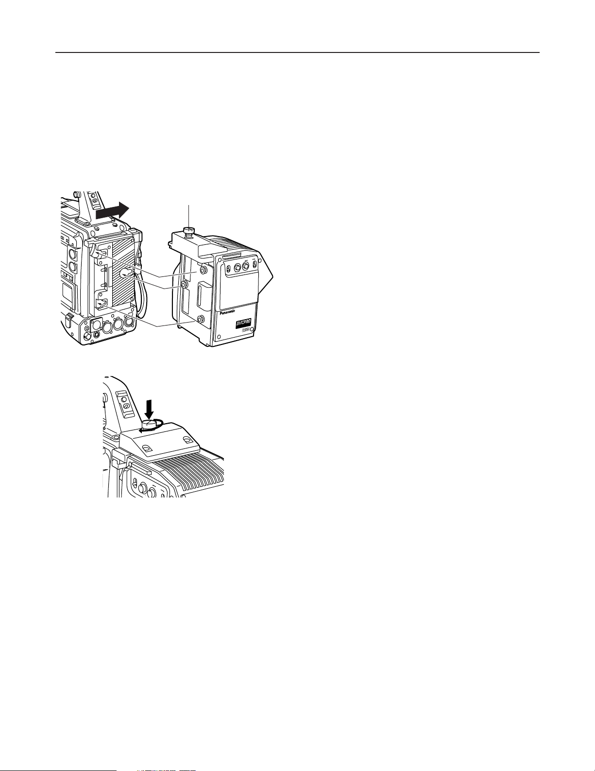
As shown in the figure on the left, align the spacer on the
back of the camera recorder with the guide in the unit, and
push the unit in the direction of the arrow until it clicks into
place.
1.
Make sure that the coin screw used to secure the AJ-CA900P connectors is unscrewed (The screw will be completely
disengaged from the thread.). Mounting the AJ-CA900P with the screw in the closed position could damage the connectors.
3.
Screw the coin screw to the closed position while pressing
down on it.
Coin screw
Follow the steps below to attach the unit to the camera recorder.
<Notes>
The spacer must be mounted on the camera recorder before the unit is attached. For details on how to mount the spacer, consult
your dealer.
Depending on the version of the software being used with the camera recorder, it may be necessary to update it, in which case you
should consult your dealer.
ON
OFF
MIC
INCOM
LEVEL
O
N
O
F
PGM
P
O
N
Page 5
- 4 -
RET 1 RET 2
INCOM
PUSH
PUSH
PGM OUT
CALL
RET SW
DC 12V IN
DC OUT
1
2
3
4
5
6
7
8
500mA
12V
Parts and their functions
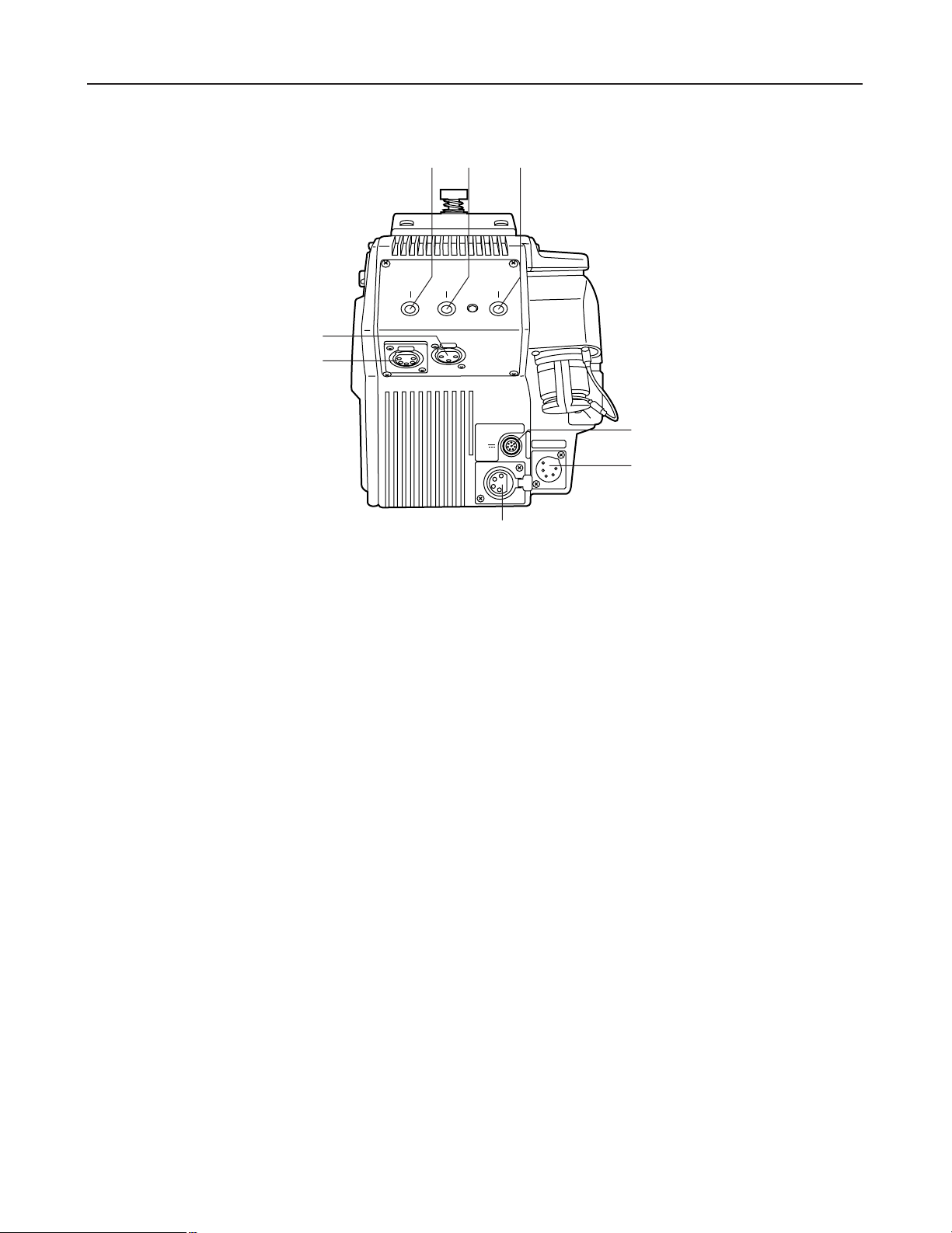
1
Return select button (RET1)
This button is used to select the return signal generated when the return switch is pressed. This button
selects RET1.
2
Return select button (RET2)
This button is used to select the return signal generated when the return switch is pressed. This button
selects RET2.
3
CALL button
This button is used to call the base station (AJ-BS900P) from the camera adapter. Pressing the CALL button
causes the CALL lamp on the AJ-BS900P to light.
4
Return switch jack (RET SW)
This jack connects to RET SW BOX. Supported functions are RET1 and RET2 selection as well as intercom
PTT (push to talk) and CALL.
Rear panel
6
DC OUT (DC power supply output) jack
This is a DC 12 V output jack. A current up to 500 mA can be output from this jack.
5
DC 12V IN (external power supply input) jack
When the unit is operated using an external power supply, the AJ-B95 AC adapter (sold separately) connects
to this jack. It is also possible to connect an external battery to this jack.
When connection is made to this jack, the external power supply is selected automatically.
7
Intercom connector
This connecter is used to connect to an intercom system via the AJ-BS900P for two-way voice connections.
8
PGM OUT connector
This is the PGM audio output connector.
Page 6
- 5 -
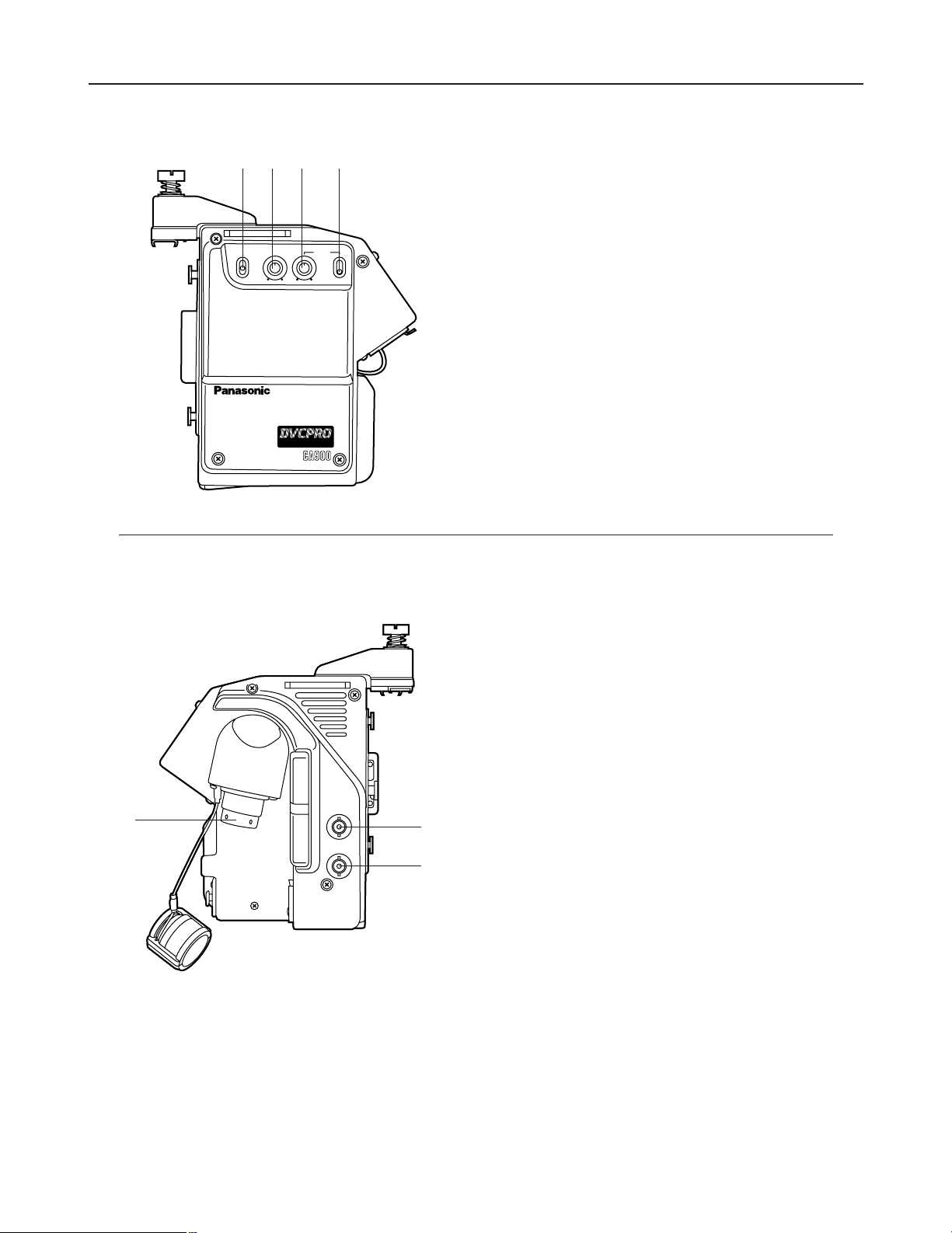
Parts and their functions
1
Microphone intercom switch (MIC)
Used to switch the intercom line between the ON, OFF,
and PTT settings. (PTT: Audio transmission continues as
long as the switch is held down.)
2
Intercom level knob (LEVEL)
This knob is used to adjust the intercom reception volume
level.
3
Program level knob (PGM)
This knob is used to adjust the intercom PGM volume level.
4
Program line switch
This switch controls the program line multiplexed on the
intercom line. It has two positions: ON and OFF.
AJ-Camera
Adapter
MIC LEVEL
INCOM
PGM
ON
OFF
ON
OFF
PTT
DIGITAL TRIAX
1
2
34
Left side
3
Triax connector
This connector is used to connect to the base station (AJBS900P) using a triax cable.
1
Prompter video output (PROMPT OUT)
The prompter video signal input to the base station (AJBS900P) is output from this jack.
2
Return video output (RET OUT)
The return video signal (either RET1 or RET2) input to the
base station (AJ-BS900P) is output from this jack.
RET-1 or RET-2 is selected by operating the return select
button (see page 4).
PROMPT
OUT
RET OUT
PROMPT
OUT
RET OUT
1
2
3
Right side
Page 7
- 6 -
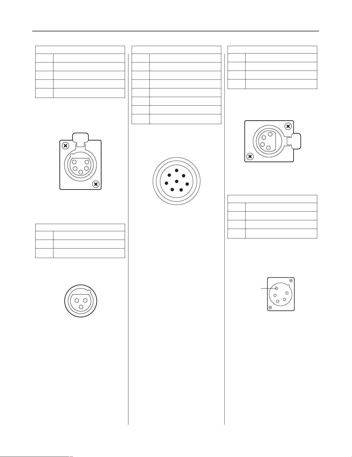
Connectors and signals
PGM OUT
1 GND
2 PGM (H)
3 PGM (C)
Manufacturer part number: HA16RM-3P
(Hirose Denki)
2
3
1
RET SW
A RET1
B MIC ON/OFF
C RET2
D TALLY
E GND
F +12V-OUT
G CALL
H GND
Manufacturer part number: PRC07-R8F
(Tajimi Musen)
A
B
C
D
E
F
G
H
5
4
3
2
1
INCOM
1 GND
2 INCOM TALK (H)
3 GND
4 INCOM RECEIVE (H)
5 PGM / RECEIVE (C)
DC 12V OUT
1 GND
2
3
4 +12V
Matsushita part number: VJS3290
Manufacturer part number: HA16PRH-5S
(Hirose Denki)
Manufacturer part number: HA16PRH-4S
(Hirose Denki)
4
3
2
1
DC IN
1 GND
2
3
4 +12V
Matsushita part number: VJP2717
Manufacturer part number:
HA16RB-4P(SW)
(Hirose Denki)
1
2
3
4
SW
Page 8

- 7 -
Selecting the intercom microphone
AJ-Camera
Adapter
MIC LEVEL
INCOM
PGM
ON
OFF
ON
OFF
PTT
DIGITAL TRIAX
1.
Remove the four screws from the side of the AJ-CA900P
shown in the figure, and remove the side panel.
2.
Refer to the figure on the left, and set the switch inside the
side panel which was removed.
Screws (4)
Dynamic
microphone
Carbon
microphone
Switch
Proceed as follows to select the dynamic microphone or carbon microphone as the intercom microphone. Before proceeding with
the work, be absolutely sure to turn off the power.
CAUTIONS:
These servicing instructions are for use by
qualified service personnel only. To reduce the
risk of electric shock do not perform any
servicing other than that contained in the
operating instructions unless you are qualified
to do so.
Page 9

- 8 -
Specifications
Input: 100 V DC (supplied by AJ-BS900P), 450mA
DC 12V IN (DC 11.5V to 17.0V), 3.2A
Power consumption: 40 W (when camera recorder and 1.5" viewfinder are attached)
10 W (AJ-CA900P main unit only)
External dimensions (W x H x D): 6-1/8" x 7-7/8" x 6-5/8" (156 x 200 x 168 (mm))
Weight: 12.1bs (2.5 kg) (including spacer)
Operating temperature range: 32 F - 104 F (0°C - 40°C)
Storage temperature range: -4 F - 131 F (-20°C - +55°C)
Operating humidity: 85% or less
Storage humidity: 0% - 90%
Transfer block
Signal transfer rate: 360 Mbps (AJ-CA900P to AJ-BS900P)
Transfer distance: 300 m with diameter 8.6 mm cable (Fujikura)
500 m with diameter 14.5 mm cable (Fujikura)
Video transfer rate
Y signal: 18 MHz sampling rate, 10-bit
R-Y signal: 9 MHz sampling rate, 10-bit
B-Y signal: 9 MHz sampling rate, 10-bit
RET signal: FM modulation
Prompt signal: FM modulation
Audio transfer rate
Signals from camera to base station: 46.875 kHz sampling rate, 16-bit
Signals from base station to camera: 11.71875 kHz sampling rate, 16-bit
Intercom
Microphone selection: Switchable between dynamic microphone and carbon microphone
I/O level: 4-line/2-line: 0 dBm (600 Ω, balanced)
RTS: 1 Vp-p (200 Ω)
PGM: 0 dB (600 Ω, balanced)
Format: Selectable between 4-line, 2-line, and RTS
Lines: Base station to camera: 2 lines (ENG, PGM)
Camera to base station: 1 line (ENG)
S/N ratio: 50 dB or more (base station to camera) (camera to base station)
Distortion: 0.3% or less
Frequency range: 100 Hz - 12 kHz (± 3 dB) (camera to base station)
100 Hz - 5.5 kHz (± 3 dB) (base station to camera)
Dynamic range: 12 dB
Video system
Teleprompt output (PROMPT): 1 Vp-p (1 Vp-p input to AJ-BS900P)
RET output: 1 Vp-p (1 Vp-p input to AJ-BS900P)
Input connectors: Intercom connector: XLR 5-pin
External power supply input connector: XLR 4-pin
RET SW connector: 8-pin
Output connectors: Teleprompt output connector: BNC VBS, 1 Vp-p, 75 Ω
(PROMPT)
EXT output connector: XLR 4-pin
RET signal output connector: BNC VBS, 1 Vp-p, 75 Ω
(RET)
PGM audio output connector: XLR 3-pin
Indicates safety-related items.
Page 10

PANASONIC BROADCAST & DIGITAL SYSTEMS COMPANY
DIVISION OF MATSUSHITA ELECTRIC CORPORATION OF AMERICA
Executive Office:
3330 Cahuenga Blvd W., Los Angeles, CA 90068 (323) 436-3500
EASTERN ZONE:
One Panasonic Way 4E-7, Secaucus, NJ 07094 (201) 348-7621
Mid-Atlantic/New England:
One Panasonic Way 4E-7, Secaucus, NJ 07094 (201) 348-7621
Southeast Region:
1225 Northbrook Parkway, Ste 1-160, Suwanee, GA 30024 (770) 338-6835
Central Region:
1707 N Randall Road E1-C-1, Elgin, IL 60123 (847) 468-5200
WESTERN ZONE:
3330 Cahuenga Blvd W., Los Angeles, CA 90068 (323) 436-3500
Dallas Region:
6226 Abington Way, Houston, TX 77008 (713) 802-2726
No. CA/Northwest Region:
5870 Stoneridge, #3, Pleasanton, CA 94588 (925) 416-5108
Government Marketing Department:
52 West Gude Drive, Rockville, MD 20850 (301) 738-3840
Panasonic Canada Inc.
5770 Ambler Drive, Mississauga, Ontario L4W 2T3 (905) 624-5010
Panasonic Sales Company
Division of Matsushita Electric of Puerto Rico Inc.
San Gabriel Industrial Park, 65th Infantry Ave., Km. 9.5, Carolina, Puerto Rico 00630 (787) 750-4300
Page 11

AJ- P
Manual d’utilisation
Adaptateur de caméra
F1100T
Printed in Japan
VQT8992
P
Page 12

1
Consignes de sécurité
ATTENTION
RISQUE DE CHOCS
ÉLECTRIQUES
NE PAS OUVRIR
ATTENTION: AFIN DE PRÉVENIR LE RISQUE DE CHOCS
ÉLECTRIQUES, NE PAS RETIRER LES VIS.
TOUTE RÉPARATION DEVRAIT ÊTRE CONFIÉE À UN
PERSONNEL COMPÉTENT.
Le symbole de l’éclair dans un triangle
équilatéral indique la présence d’une tension
suffisamment élevée pour engendrer un
risque de chocs électriques.
Le point d’exclamation dans un triangle
équilatéral indique que le manuel
d’instructions inclus avec l’appareil contient
d’importantes recommandations quant au
fonctionnement et à l’entretien de ce dernier.
MISE EN GARDE:
AFIN DE PRÉVENIR TOUT RISQUE
D’INCENDIE OU DE CHOCS ÉLECTRIQUES,
ÉVITER D’EXPOSER CET APPAREIL À LA
PLUIE OU À UNE HUMIDITÉ EXCESSIVE.
ATTENTION:
AFIN DE PRÉVENIR TOUT RISQUE
D’INCENDIE, DE CHOCS ÉLECTRIQUES OU
D’INTERFÉRENCES, N’UTILISER QUE LES
ACCESSOIRES RECOMMANDÉS.
ATTENTION:
POUR EVITER TOUT RISQUE DE FEU OU DE
CHOC ELECTRIQUE, CONFIER LE REGLAGE
DES COMMUTATEURS INTERNES A UN
PERSONNEL QUALIFIE.
indique les consignes de sécurité.
Page 13

2
Consignes de sécurité............................................................... 1
Caractéristiques......................................................................... 2
Installation ................................................................................. 3
Les commandes et leurs fonctions............................................ 4
Panneau arrière ..........................................................................................4
Panneau latéral gauche..............................................................................5
Panneau latéral droit...................................................................................5
Sélection du microphone d’intercom ......................................... 6
Brochage des connecteurs........................................................ 7
Fiche technique ......................................................................... 8
Table des matières
L’appareil offre les caractéristiques suivantes.
≥ Il permet la transmission d’images à haute qualité au moyen de signaux à composantes série de 360 Mbps à large bande
non compressés.
≥ Il utilise un câble triaxial.
≥ Il permet à un camescope DVCPRO de fonctionner comme caméra système.
≥ Il permet une transmission jusqu’à une distance de 2 000 mètres moyennant l’utilisation de trois répéteurs AJ-RP900P. (*1)
≥ Il permet la transmission des signaux de deux canaux audio.
≥ Il permet la transmission de RET 1CH et PROMPT 1CH.
≥ Il s’installe ou se retire en toute facilité sur le camescope à l’aide de l’entretoise.
≥ La zone des connecteurs TRIAX pivote à des fins de commodité.
≥ Il est doté de connecteurs de sortie RET et PROMPT (BNC).
≥ Il est doté d’une prise de sortie CC 12 V.
Caractéristiques
*1 L’alimentation est soumise à des restrictions. Consulter son revendeur pour la configuration du système.
Nous vous remercions d’avoir choisi cet adaptateur de caméra AJ-CA900P (qui sera simplement appelé “l’appareil” dans la suite de
ce mode d’emploi).
L’appareil s’installe dans un camescope DVCPRO ou DVCPRO50 pour configurer un système de transmission utilisant un câble
triaxial pour permettre au camescope de fonctionner comme caméra système.
L’utilisation de signaux à composantes série de 360 Mbps à large bande non compressés rend possible une transmission à haute
qualité d’image, de façon que les images haute qualité prises par le camescope DVCPRO soient transmises avec leur haute qualité
d’image intacte. Ceci contribue à élargir la plage des formats que le camescope DVCPRO est capable de traiter.
Remarque:
≥≥
Lorsque l’appareil est raccordé, il n’est pas possible d’enregistrer les signaux d’entrée externes sur
la bande du camescope. Il faudra sélectionner “CAM” comme paramètre de REC SIGNAL sur le
menu REC/PB/RET du camescope.
≥≥
Lorsque l’appareil est alimenté sur une alimentation externe (CC 12 V), toujours enclencher
l’interrupteur d’alimentation de la station de base (AJ-BS900P) avant de mettre le camescope sous
tension.
Page 14

3
Installation
A
J
-
C
a
m
e
r
a
A
d
a
p
t
e
r
M
IC LE
VE
L
IN
C
O
M
P
G
M
ON
OFF
ON
OFF
PTT
D
IG
IT
A
L
T
R
IA
X
I
M
P
O
R
T
A
N
T
N
O
T
T
O
B
E
U
S
E
D
A
S
A
C
H
A
R
G
E
A
D
A
P
T
E
R
2.
Comme indiqué sur la figure de gauche, amener l’entretoise
au dos du camescope en regard du guide tracé sur l’appareil,
et pousser l’appareil dans le sens de la flèche jusqu’à ce qu’il
se mette en place dans un déclic.
1.
Vérifier que la vis à fente pour pièce de monnaie qui sert à fixer les connecteurs de l’AJ-CA900P est dévissée. (La vis se retire
complètement du filetage.) Le fait de monter l’AJ-CA900P avec la vis en position de fermeture risque d’endommager les
connecteurs.
3.
Visser la vis à fente pour pièce de monnaie sur la position de
fermeture tout en appuyant dessus.
Vis à fente pour pièce de monnaie
Effectuer les opérations ci-dessous pour fixer l’appareil au camescope.
<Remarques>
L’entretoise devra être montée sur le camescope pour pouvoir fixer l’appareil. Pour les détails sur le montage de l’entretoise,
consulter son revendeur.
Selon la version du logiciel du camescope, il faudra peut-être effectuer une mise à niveau, auquel cas il faudra consulter son
revendeur.
ON
OFF
MIC
INCOM
LEVEL
O
N
O
F
PGM
P
ON
Page 15

4
RET 1 RET 2
INCOM
PUSH
PUSH
PGM OUT
CALL
RET SW
DC 12V IN
DC OUT
1
2
3
4
5
6
7
8
500mA
12V
Les commandes et leurs fonctions
1
Touche de sélection de retour (RET1)
Cette touche permet de sélectionner le signal de retour généré lorsqu’on appuie sur le commutateur de
retour. Cette touche sélectionne le signal RET1.
2
Touche de sélection de retour (RET2)
Cette touche permet de sélectionner le signal de retour généré lorsqu’on appuie sur le commutateur de
retour. Cette touche sélectionne le signal RET2.
3
Touche d’appel (CALL)
Cette touche permet d’appeler la station de base (AJ-BS900P) depuis l’adaptateur de caméra. Quand on
appuie sur la touche CALL, le voyant CALL de l’AJ-BS900P s’allume.
4
Prise de commutateur de retour (RET SW)
Cette prise se raccorde à RET SW BOX. Les fonctions supportées sont la sélection RET1 et RET2, ainsi que
les fonctions PTT (“conversation”) et CALL de l’intercom.
Panneau arrière
6
Prise de sortie d’alimentation CC (DC OUT)
C’est une prise de sortie de 12 V CC. Il est possible d’envoyer un courant de 500 mA maximum par cette
prise.
5
Prise d’entrée d’alimentation externe (DC 12V IN)
Lorsque l’appareil est alimenté sur une alimentation externe, raccorder l’adaptateur secteur AJ-B95 (vendu
séparément) à cette prise. Il est également possible de raccorder une batterie externe à cette prise.
Lorsqu’on effectue le raccordement à cette prise, l’alimentation externe se sélectionne automatiquement.
7
Connecteur d’intercom
Ce connecteur se raccorde à un système d’intercom via l’AJ-BS900P en vue d’une communication
bidirectionnelle.
8
Connecteur de sortie PGM (PGM OUT)
C’est le connecteur de sortie audio PGM.
Page 16

5
Les commandes et leurs fonctions
1
Commutateur intercom de microphone (MIC)
Permet de commuter la ligne intercom entre ON, OFF et
PTT. (PTT : la transmission audio se poursuit tout le temps
que la touche est maintenue enfoncée.)
2
Bouton de niveau d’intercom (LEVEL)
Ce bouton permet de régler le niveau du volume de
réception de l’intercom.
3
Bouton de niveau de programme (PGM)
Ce bouton permet de régler le niveau du volume PGM de
l’intercom.
4
Commutateur de ligne de programme
Ce commutateur contrôle la ligne de programme
multiplexée sur la ligne intercom. Il possède deux positions
: ON et OFF.
AJ-Camera
Adapter
MIC LEVEL
INCOM
PGM
ON
OFF
ON
OFF
PTT
DIGITAL TRIAX
1
2
34
Panneau latéral gauche
3
Connecteur triax
Ce connecteur permet le raccordement à la station de base
(AJ-BS900P) à l’aide d’un câble triaxial.
1
Sortie vidéo de prompteur (PROMPT OUT)
Le signal vidéo du prompteur envoyé à la station de base
(AJ-BS900P) est envoyé par cette prise.
2
Sortie vidéo de retour (RET OUT)
Le signal de sortie vidéo (RET1 ou RET2) envoyé à la station
de base (AJ-BS900P) est envoyé par cette prise.
RET-1 ou RET-2 se sélectionnent avec la touche de sélection
de retour (voir page 5).
PROMPT
OUT
RET OUT
PROMPT
OUT
RET OUT
1
2
3
Panneau latéral droit
Page 17

6
Brochage des connecteurs
PGM OUT
1 Terre
2 PGM (H)
3 PGM (C)
Numéro de pièce du fabricant
: HA16RM-3P
(Hirose Denki)
2
3
1
RET SW
A RET1
B
Marche/arrêt de microphone
C RET2
D Signalisation
E Terre
F +12V-OUT
G Appel
H Terre
Numéro de pièce du fabricant
: PRC07-R8F
(Tajimi)
A
B
C
D
E
F
G
H
5
4
3
2
1
INCOM
1 Terre
2 Voix incom (H)
3 Terre
4Réception incom (H)
5 PGM/réception (C)
DC 12V OUT
1 Terre
2
3
4 +12V
Numéro de pièce Matsushita: VJS3290
Numéro de pièce du fabricant: HA16PRH-5S
(Hirose Denki)
Numéro de pièce du fabricant
:
HA16PRH-4S
(Hirose Denki)
4
3
2
1
DC IN
1 Terre
2
3
4 +12V
Numéro de pièce Matsushita: VJP2717
Numéro de pièce du fabricant:
HA16RB-4P(SW)
(Hirose Denki)
1
2
3
4
SW
Page 18

7
Sélection du microphone intercom
AJ-Camera
Adapter
MIC LEVEL
INCOM
PGM
ON
OFF
ON
OFF
PTT
DIGITAL TRIAX
1.
Retirer les quatre vis sur le côté de l’AJ-CA900P comme
indiqué sur la figure, et retirer le panneau latéral.
2.
En se reportant à la figure de gauche, régler le commutateur
à l’intérieur du panneau latéral que l’on vient de retirer.
Vis (4)
Microphone
dynamique
Microphone
au carbone
Commutateur
Pour sélectionner le microphone dynamique ou le microphone au carbone comme microphone intercom, procéder de la façon
suivante. Avant de procéder, il faudra absolument mettre l’appareil hors tension.
ATTENTION :
Ces instructions d’entretien sont exclusivement
réservées au personnel d’entretien qualifié.
Pour réduire tout risque de choc électrique,
n’effectuer aucune autre opération d’entretien
que celles qui figurent dans le mode d’emploi,
à moins d’être qualifié pour ce genre de travail.
Page 19

8
Fiche technique
Entrée: 100 V DC (supplied by AJ-BS900P), 450mA
DC 12V IN (CC 11,0-17,0, 12 A), 3.2A
Consommation: 40 W (lorsque le camescope et le viseur 1,5" sont fixés)
10 W (appareil principal AJ-CA900P seulement)
Dimensions externes (L x H x P): 156 x 200 x 168 (mm)
Poids: 2,5 kg (avec l’entretoise)
Plage de température de fonctionnement: 0°C - 40°C
Plage de température de rangement: -20°C - +55°C
Humidité de fonctionnement: 85% maximum
Humidité de rangement: 0% - 90%
Module de transfert
Débit du signal: 360 Mbps (AJ-CA900P à AJ-BS900P)
Distance de transfert: 300 m avec un câble de 8,6 mm de diamètre (Fujikura)
500 m avec un câble de 14,5 mm de diamètre (Fujikura)
Débit vidéo
Signal Y: Taux d’échantillonnage de 18 MHz, 10 bits
Signal R-Y: Taux d’échantillonnage de 9 MHz, 10 bits
Signal B-Y: Taux d’échantillonnage de 9 MHz, 10 bits
Signal RET: Modulation FM
Signal de guidage: Modulation FM
Débit audio
Envoi des signaux de la caméra à la station de base: Taux d’échantillonnage de 46,875 kHz, 16 bits
Envoi des signaux de la station de base à la caméra: Taux d’échantillonnage de 11,71875 kHz, 16 bits
Intercom
Sélection du microphone: Sélection microphone dynamique/microphone au carbone
Niveau d’E/S: 4 lignes/2 lignes: 0 dBm (600 Ω, symétrique)
RTS: 1 Vcac (200 Ω)
PGM: 0 dB (600 Ω, symétrique)
Format: Sélection entre 4 lignes, 2 lignes et RTS
Lignes: Station de base vers caméra: 2 lines (ENG, PGM)
Caméra vers station de base: 1 ligne (ENG)
Rapport signal/bruit: 50 dB ou plus
(station de base vers caméra) (caméra vers station de base)
Distorsion: 0,3% ou moins
Plage de fréquence: 100 Hz-12 kHz (±3 dB) (caméra vers station de base)
100 Hz-5,5 kHz (±3 dB) (station de base vers caméra)
Plage dynamique: 12 dB
Système vidéo
Sortie de téléprompteur: 1 Vcac (entrée 1 Vcac à AJ-BS900P)
Sortie RET: 1 Vcac (entrée 1 Vcac à AJ-BS900P)
Connecteurs d’entrée: Connecteur intercom: XLR 5 broches
Connecteur d’entrée d’alimentation externe:XLR 4 broches
Connecteur RET SW: 8 broches
Connecteurs de sortie: Connecteur de sortie de téléprompteur: BNC VBS, 1 Vcac, 75 Ω
(PROMPT)
Connecteur de sortie EXT: XLR 4 broches
Connecteur de sortie de signal RET: BNC VBS, 1 Vcac, 75 Ω
(RET)
Connecteur de sortie audio PGM: XLR 3 broches
Informations concernant la sécurité
Page 20

Panasonic Canada Inc.
5770 Ambler Drive, Mississauga, Ontario L4W 2T3 (905) 624-5010
Page 21

documentation manual, user maintenance, brochure, user reference, pdf manual
This file has been downloaded from:
User Manual and User Guide for many equipments like mobile phones, photo cameras, monther board, monitors, software, tv, dvd, and othes..
Manual users, user manuals, user guide manual, owners manual, instruction manual, manual owner, manual owner's, manual guide,
manual operation, operating manual, user's manual, operating instructions, manual operators, manual operator, manual product,
 Loading...