

Model No. AJ-
Thank you for purchasing this product.
Before operating this product, please read the instructions carefully and save this manual for future use.
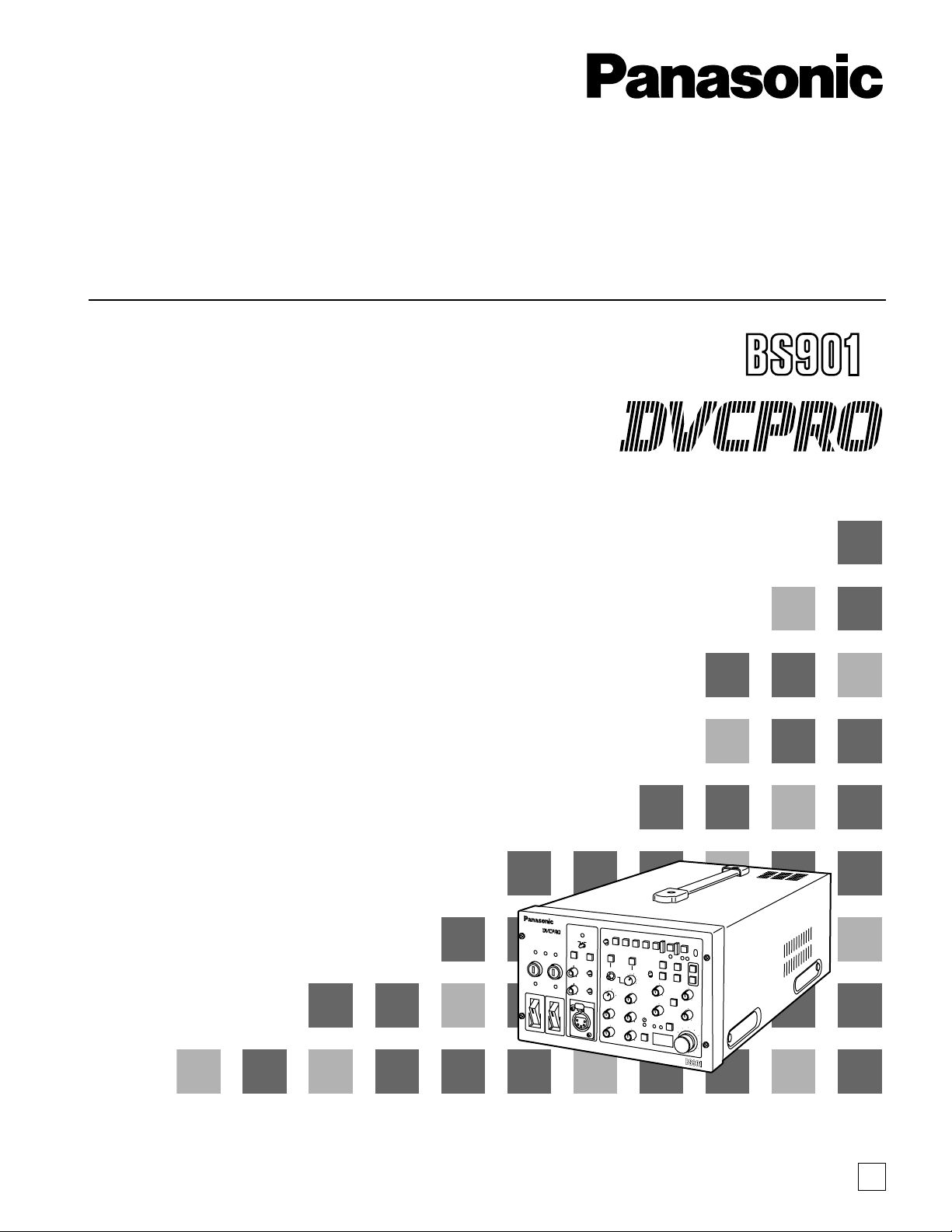
Operating Instructions
Digital Triax Base Station
S
.S
P
EN
F0903H0
@
3
Printed in Japan
VQT0F82
EN
2
Safety precautions
General
CAUTION:
TO REDUCE THE RISK OF FIRE OR SHOCK
HAZARD AND ANNOYING INTERFERENCE,
USE THE RECOMMENDED ACCESSORIES
ONLY.
WARNING:
•
TO REDUCE THE RISK OF FIRE OR
SHOCK HAZARD, DO NOT EXPOSE THIS
EQUIPMENT TO RAIN OR MOISTURE.
• TO REDUCE THE RISK OF FIRE OR SHOCK
HAZARD, KEEP THIS EQUIPMENT AWAY
FROM ALL LIQUIDS—USE AND STORE
ONLY IN LOCATIONS WHICH ARE NOT
EXPOSED TO THE RISK OF DRIPPING OR
SPLASHING LIQUIDS, AND DO NOT PLACE
ANY LIQUID CONTAINERS ON TOP OF THE
EQUIPMENT.
CAUTION:
Do not install or place this unit in a bookcase,
built-in cabinet or any other confined space in
order to maintain adequate ventilation. Ensure
that curtains and any other materials do not
obstruct the ventilation to prevent risk of
electric shock or fire hazard due to
overheating.
indicates safety information.
CAUTION:
EVEN WHEN THE POWER SWITCH IS IN
THE OFF POSITION, A SMALL CURRENT
FLOWS THE FILTER CIRCUIT.
CAUTION:
THE AC OUTLET (MAINS SOCKET) SHALL
BE INSTALLED NEAR THE EQUIPMENT AND
SHALL BE EASILY ACCESSIBLE.
THIS APPARATUS MUST BE GROUNDED
To ensure safe operation the three-pin plug must be
inserted only into a standard three-pin power outlet
(socket) which is effectively grounded through the
normal household wiring.
Extension cords used with the equipment must be
three-core and be correctly wired to provide
connection to the ground. Incorrectly wired extension
cords can be extremely hazardous.
The fact that the equipment operates satisfactorily
does not imply that it is grounded, and the installation
is not necessarily safe. For your safety, if in any
doubt about the effective grounding of the equipment
or power outlet (socket), please consult a qualified
electrician.
Operating precaution
Operation near any appliance which generates
strong magnetic fields may give rise to noise in
the video and audio signals. If this should be the
case, deal with the situation by, for instance,
moving the source of the magnetic fields away
from the unit before operation.
CAUTION:
TO REDUCE THE RISK OF FIRE OR SHOCK
HAZARD, REFER MOUNTING OF THE
OPTIONAL BOARD AND CHANGE OF
SWITCH SETTINGS INSIDE THE UNIT TO
QUALIFIED SERVICE PERSONNEL.
WARNING:
THE CONNECTOR (TRIAX) MARKED WITH
AN ARROW ( ) CONTAINS HAZARDOUS
VOLTAGE.
TO REDUCE THE RISK OF ELECTRIC
SHOCK, CONNECTIONS USING THIS
CONNECTOR MUST BE PERFORMED ONLY
BY QUALIFIED PERSONNEL OR BY USING
READY-MADE LEADS OR CORDS.
3
CAUTION
RISK OF ELECTRIC SHOCK
DO NOT OPEN
CAUTION: TO REDUCE THE RISK OF ELECTRIC SHOCK,
DO NOT REMOVE COVER (OR BACK).
NO USER SERVICEABLE PARTS INSIDE.
REFER TO SERVICING TO QUALIFIED SERVICE PERSONNEL.
The lightning flash with arrowhead symbol,
within an equilateral triangle, is intended to
alert the user to the presence of uninsulated
“dangerous voltage” within the product’s
enclosure that may be of sufficient magnitude
to constitute a risk of electric shock to
persons.
The exclamation point within an equilateral
triangle is intended to alert the user to the
presence of important operating and
maintenance (service) instructions in the
literature accompanying the appliance.
FCC Note:
This device complies with Part 15 of the FCC Rules.
To assure continued compliance follow the attached
installation instructions and do not make any
unauthorized modifications.
This equipment has been tested and found to comply
with the limits for a class A digital device, pursuant to
Part 15 of the FCC Rules. These limits are designed
to provide reasonable protection against harmful
interference when the equipment is operated in a
commercial environment. This equipment generates,
uses, and can radiate radio frequency energy and, if
not installed and used in accordance with the
instruction manual, may cause harmful interference to
radio communications. Operation of this equipment in
a residential area is likely to cause harmful
interference in which case the user will be required to
correct the interference at his own expense.
Safety precautions
Model AJ-BS901P
∫∫
DO NOT REMOVE PANEL COVER BY
UNSCREWING.
To reduce the risk of electric shock, do not remove
cover. No user serviceable parts inside.
Refer servicing to qualified service personnel.
Model AJ-BS901EN
4
FOR U.K. ONLY
This appliance is supplied with a moulded three pin
mains plug for your safety and convenience.
A 13 amp fuse is fitted in this plug.
Should the fuse need to be replaced please ensure that
the replacement fuse has a rating of 13 amps and that it
is approved by ASTA or BSI to BS1362.
Check for the ASTA mark Ïor the BSI mark Ìon the
body of the fuse.
If the plug contains a removable fuse cover you must
ensure that it is refitted when the fuse is replaced.
If you lose the fuse cover the plug must not be used
until a replacement cover is obtained.
A replacement fuse cover can be purchased from your
local Panasonic Dealer.
IF THE FITTED MOULDED PLUG IS UNSUITABLE
FOR THE SOCKET OUTLET IN YOUR HOME THEN
THE FUSE SHOULD BE REMOVED AND THE PLUG
CUT OFF AND DISPOSED OF SAFELY. THERE IS A
DANGER OF SEVERE ELECTRICAL SHOCK IF THE
CUT OFF PLUG IS INSERTED INTO ANY 13 AMP
SOCKET.
If a new plug is to be fitted please observe the wiring
code as shown below.
If in any doubt please consult a qualified electrician.
WARNING: THIS APPLIANCE MUST BE EARTHED.
IMPORTANT: The wires in this mains lead are coloured
in accordance with the following code:
Green-and-Yellow: Earth
Blue: Neutral
Brown: Live
Caution for AC Mains Lead
As the colours of the wires in the mains lead of this
appliance may not correspond with the coloured
markings identifying the terminals in your plug, proceed
as follows:
• The wire which is coloured GREEN-AND-YELLOW
must be connected to the terminal in the plug which is
marked with the letter E or by the Earth symbol Óor
coloured GREEN or GREEN-AND-YELLOW.
• The wire which is coloured BLUE must be connected
to the terminal in the plug which is marked with the
letter N or coloured BLACK.
• The wire which is coloured BROWN must be
connected to the terminal in the plug which is marked
with the letter L or coloured RED.
FOR YOUR SAFETY PLEASE READ THE FOLLOWING TEXT CAREFULLY.
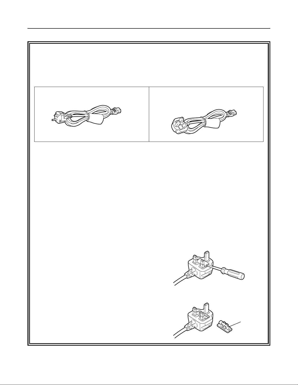
This product is equipped with 2 types of AC mains cable. One is for continental Europe, etc. and the other one is only
for U.K.
Appropriate mains cable must be used in each local area, since the other type of mains cable is not suitable.
FOR CONTINENTAL EUROPE, ETC.
Not to be used in the U.K.
FOR U.K. ONLY
If the plug supplied is not suitable for your socket
outlet, it should be cut off and appropriate one fitted.
How to replace the fuse
1.Open the fuse compartment with a screwdriver.
2.Replace the fuse.
Fuse
Safety precautions
Model AJ-BS901EN

5
Safety precautions..................................................................... 2
Features .................................................................................... 6
Checkpoints for system connections......................................... 6
Parts and their functions............................................................ 7
Front panel..................................................................................................7
Rear panel ................................................................................................11
PIX output menu indications.................................................... 13
PIX output setting menu indications .........................................................13
Structure of setting menus........................................................................13
MAIN MENU 1/2 screen .......................................................... 14
MAIN MENU 2/2 screen .......................................................... 16
Shading adjustment................................................................. 17
Shading menu operation procedure (example: black shading) ................17
Connectors and signals........................................................... 18
Switches .................................................................................. 20
Removing the boards................................................................................20
Setting the board switch positions ............................................................21
Setting the microswitch position ...............................................................22
Switching the controller.............................................................................22
Specifications .......................................................................... 23
Contents
Thank you very much for purchasing this AJ-BS901 Base Station (referred to throughout these instructions as “the unit”).
The unit is used together with the AJ-CA901 camera adapter and connected to a DVCPRO50 camera recorder to configure a
transmission system which uses a tri-axial cable to enable the camera recorder to be operated as a system camera.
Use of non-compressed wide-band 360 Mbps serial component signals makes high picture quality transmission possible so
that the high picture quality of the images shot by the DVCPRO camera recorder are transmitted with their high picture quality
kept intact.
This serves to expand the range of the DVCPRO camera recorder’s operating formats.
Note
≥ When the unit is connected, external input signals cannot be recorded on tape inside the camera recorder.
“CAM” must be selected as the REC SIGNAL setting on the SYSTEM SETTING menu of the camera recorder.
Accessories
≥≥
Operating instructions
≥≥
Power cord: 1 pc
≥≥
Warranty card
≥≥
Connectors (For WFM CONTROL, COMMUNICATION, TALLY)
≥≥
List of service centers

6
Features
The unit has the following features.
≥ It enables high picture quality transmission by means of non-compressed wide-band 360 Mbps serial component signals.
≥ It uses a tri-axial cable.
≥ It enables a DVCPRO camera recorder to be operated as a system camera.
≥ It enables the transmission of the signals of two audio channels.
≥ It enables RET 1CH and PROMPT 1CH transmission.
≥ It has a compact size equivalent to one-half of a rack unit.
≥ It can also be operated using DC power.
≥ It can perform the VTR operations of the camera recorder.
Bear in mind the following checkpoints when connecting the camera recorder to the unit’s system.
1 When using this unit with a system to which a camera recorder is connected, an AJ-SDX900 model must be used for this unit
to function.
Depending on the version of the software being used with the camera recorder, it may be necessary to update it, in which
case you should consult your dealer.
2 The triax and ECU (extension control unit) cannot be used at the same time for the camera recorder.
3 When the triax is connected, some of the settings (such as GAIN, CAM-BAR SW, WHITE BAL, SHUTTER and USER SW)
selected by the switches on the camera recorder will not take effect.
4 When the triax is connected, the composite video signals (MON OUT, VIDEO OUT) of the camera recorder will be non-
standard signals.
Checkpoints for system connections
7
Parts and their functions
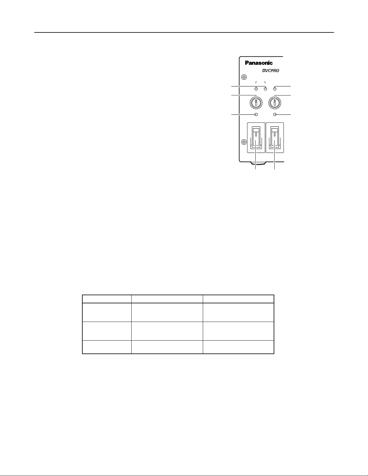
Front panel
CABLE
SHORT ALARM
FUSE
HEAD POWER
ON
OFF
MAIN
ON
OFF
FUSE
OPEN
DIGITAL TRIAX
1
2
4
5
6
3
7
8
400V 1A
250V T 2.5A L
5
Power fuse (FUSE)
This is the main power supply fuse of the AJ-BS901. Use a dedicated DC fuse (400V 1A) which can withstand inrush.
6
Camera AC power fuse (FUSE)
This is the fuse of the power supply to the camera head. Use a dedicated DC fuse (400V 1A) which can withstand inrush.
7
CABLE indicators
These indicators show the status of the camera cable.
OPEN: Indicates that the camera cable is open. (In cases where, for instance, a connector has become disconnected or a wire
has broken.) The power supply to the camera is off when this indicator is lit.
SHORT: Indicates that the camera cable is shorted. The power supply to the camera is off when this indicator is lit. If the
SHORT indicator lights, the cable needs to be inspected.
8
ALARM indicator
This indicator blinks when a problem has occurred. If a monitor has been connected to PIX OUT, letters representing the alarm
concerned will be displayed on the monitor simultaneously. For further details, refer to the table below.
1
MAIN switch
This is the on/off switch for the main power supply.
This switch operates only when the unit is operated on AC
power. It does not work when it is operated on DC power.
<Note>
When DC power is supplied, whether the switch is ON or
OFF depends on whether the main power switch on the DC
power supply is ON or OFF.
2
HEAD POWER switch
This is the on/off switch for the power supply to the camera
head.
3
MAIN power indicator
Lights when the main power supply is turned on.
4
Head power indicator
Lights when the power supply to the camera head (AJ-CA901) is turned on.
ALARM LED status
Blinks rapidly
Blinks slowly
Lights
Description of alarm
The indicator lights when 1 and
2 have occurred simultaneously.
1 The temperature inside the unit
is higher than the reference
value.
2 One or both fans have stopped
working because a problem
has occurred.
“TEMP HI!”
“FAN STOP!”
“TEMP HI & FAN STOP!”
Letters spelling out the alarm
8
=
MIC button
This button is used to switch the intercom microphone on and off. It has three positions: ON, OFF, and PTT. (PTT: Audio
transmission continues as long as the button is held down.)
<
INTERCOM level knob
This knob is used to adjust the volume of the microphone
input to the intercom.
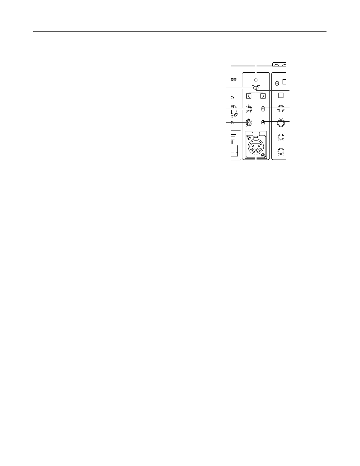
Parts and their functions
Front panel
GENLOCK
VTR
ENABLE
REW
SET UP
MON SEL
KNEE
POINT
KNEE
SLOPE
ON
OFF
(PUSH)
OFFSC H
PHASE
INTERCOM
PGM
ON
OFF
PTT
MIC
PRIVATE
SYSTEM
PUSH
PHASE
ON
OFF
R
G
B SUP
RIAX
9
:
;
<
?
@
>
=
9
Intercom XLR connector
This is used to connect a headset to the intercom.
:
PGM level knob
This knob is used to adjust the volume of the PGM audio
mixed into the signal fed to the intercom headset.
?
Phase adjustment buttons
These buttons are used to adjust the phase selected using the phase adjustment switch >.
;
SYSTEM/PRIVATE selector switch
This is used to toggle the intercom between the system and
private modes.
SYSTEM: The intercom is connected to the system via the
communication connector on the rear panel of
the unit.
PRIVATE:The intercom is not connected to the system via
the communication connector on the rear panel
of the unit.
<Note>
When this unit is used without the camera head (AJ-CA901
camera adapter and AJ-SDX900 camera recorder)
connected, the conditions for PRIVATE are established,
irrespective of the setting of this switch.
>
Phase adjustment switch
The available settings are SC PHASE, OFF, and H PHASE.
SC PHASE: Selects SC phase adjustment.
OFF: No phase adjustment is performed.
H PHASE: Selects H phase adjustment.
@
GEN LOCK indicator
This indicator lights when the camera’s synchronization is locked using the signal input via the GEN LOCK connectors on the
rear panel.

9
Parts and their functions
M
AWB button
This is the auto white balance button. It does not work
when the L WHITE BAL switch is set to the PRST position.
Button LED lit: Auto white balance in progress.
Button LED dark:Auto white balance completed.
Button LED stops blinking and goes off:
Auto white balance error.
N
ABB button
This is the auto black balance button.
Button LED lit: Auto black balance in progress.
Button LED dark:Auto black balance completed.
Button LED stops blinking and goes off:
Auto white balance error.
O
BAR switch
This switch is used to output a bar signal from the AJBS901. The camera head does not switch to bar mode.
H
VTR WARNING indicator
This indicator lights when a VTR operation error occurs.
I
CALL button
This button is used to call the camera. This button’s LED
lights when a call is made from the camera.
K
G TALLY indicator
This indicator lights when an G tally signal is being input via
the TALLY IN connector.
J
R TALLY indicator
This indicator lights when a R tally signal is being input via
the TALLY IN connector.
Front panel
L
WHITE BAL (white balance selector) switch
PRST: This position should be selected when there is no
time to adjust the white balance. It uses the 3200
K white balance value stored in memory.
A or B: The white balance memory is set to A or B.
VTR
ENABLE
WHITE
BAL
REW
Base Station AJ-
FF STOP
SHUTTERSET UP
MON SEL
KNEE
POINT
KNEE
SLOPE
GAMMA
DETAIL
M.PED
PLAY
AWB
CHECK
AUTO IRIS
IRIS
BR
GAIN
FILTER
ABB
BAR
ENABLE
PAINTING
GAIN
AUTO KNEE
GAIN
REC CHK
START / STOP
CALL
TALLY
VTR WARNING
ON
OFF
(PUSH)
PRST
A
B
BLACK
RGENG
SEQ
B SUP
S.V
S.S.
100(60)
1000
120
250
500
2000
^
BEC
DFG
H
J
I
K
L
N
O
M
R
S
T
U
V
W
X
YZ[
\
]
`
d
Q
P
e
6
5
ª
1
A
_
a
b
c
B
REW button
This is the rewind button for the VTR.
C
FF button
This is the fast forward button for the VTR.
D
STOP button
This is the stop button for the VTR.
E
PLAY button
This is the play button for the VTR.
F
REC CHK button
This button is used to display the recording status of the
VTR.
G
START/STOP button
This button is used to turn the VTR’s recording operation on
and off.
A
VTR ENABLE button
This button is used to operate the VTR from the base
station.
ON: Activates VTR operation using the controls on the
front panel (buttons B to G). The time code is
displayed at PIX OUT.
OFF: Deactivates VTR operation using the controls on the
front panel. The time code is not displayed at PIX
OUT.
<Note>
The VTR’s playback video signal is not output from the base
station.

10
Parts and their functions
Front panel
a
MON SEL switch
This switch is used to switch the signals output from the PIX
and WFM jacks on the rear panel of the AJ-BS901.
_
KNEE POINT knob
This knob is used to set the manual knee point.
`
DETAIL knob
This knob allows adjustment of the master DETAIL setting.
^
GAMMA knob
This knob is used to change the camera’s master gamma
setting.
b
SET UP button
This button is used to make camera settings.
When it is lighted, menus are displayed at PIX OUT.
c
SET UP dial
This dial is used to select settings on the setting menus.
After selecting the desired setting by turning the dial, press
to enter it.
Menu settings can be performed when the b SET UP
button is lighted.
When the b SET UP button is not lighted, the SYNCHRO
SCAN speed can be set; when SYNCHRO SCAN is
selected.
If the SET UP dial is rotated while it is being
held down, the speed setting for SYNCHRO SCAN will
change continuously.
e
Shutter speed selector switch
This switch is used to select the shutter speed. The
available settings are SYNCHRO SCAN Super V and 1/100
to 1/2000.
Moving the switch when the SHUTTER button is in the off
position will not cause the shutter to operate.
d
SHUTTER button
This button activates the operation performed using the
shutter speed selector switch e. It should be put into the
on position when using an electronic shutter.
[
! indicator
This lights when the lens extenders (a2) are used with the
camera.
]
KNEE SLOPE knob
This knob is used to set the manual knee slope.
R
PAINTING ENABLE button
This button is used to enable painting (gain knob S and
black knob T) operation.
V
AUTO IRIS button
This button is used to toggle auto iris operation on and off.
Lit: Auto iris operation on.
Dark: Auto iris operation off.
W
LED digital indicator
This indicator displays the F value of the lens.
When changes are made to the gain or filter settings, the
corresponding values are displayed for about two seconds.
Also, pressing the CHECK button Z toggles the display in
sequence among the gain, filter, and F values.
<Note>
“---” appears when the camera recorder’s power is OFF.
U
IRIS knob
When the AUTO IRIS button V is in the on position, the
value selected using this knob is added or subtracted to the
A. IRIS LEVEL setting in the MENU.
When the AUTO IRIS button V is in the off position, this
knob is used to perform adjustment of the iris setting.
<Note>
Set the lens manual/auto selector switch to AUTO.
Y
FILTER indicator
This indicator lights when the filter position is shown by the
LED digital indicator.
X
GAIN indicator
This indicator lights when the gain value is shown by the
LED digital indicator.
\
M PED knob
This knob is used to adjust the master pedestal setting.
Z
CHECK button
Pressing this button multiple times causes first the GAIN
indicator and then the FILTER indicator to light. When the
GAIN indicator is lit the LED digital indicator shows the filter
position, and when the FILTER indicator is lit the LED digital
indicator shows the gain value.
S
GAIN knobs
These are the R and B gain adjustment knobs.
T
BLACK knobs
These are the R and B pedestal adjustment knobs.
P
AUTO KNEE button
This button is used to toggle auto knee operation on and off.
Lit: Auto knee operation on.
Dark: Auto knee operation off.
Q
GAIN buttons
These buttons are used to switch the camera’s gain setting.

11
Parts and their functions
EXT DC IN
GEN–
LOCK
ENC
1
ENC
2
ENC
3
PIX
Y/G
4:2:2
4:2:2
SDI OUTOUTIN
OP4
OP3
WFM
TALLY
FUSE 400V 15A
SIGNAL
GND
AC IN
AUDIO
OUT
CH 1
PUSH
CH 2
PUSH
COMMUNICATION
PB/B
PR/R
WFM
RET 1
RET 2
PROMPT
1
2
3
4
5
7689
:
;
=
>
<
?
@
A
B
C
D
E
ENC
1
ENC
2
ENC
3
PIX
Y/G
4:2:2
4:2:2
SDI OUTOUT
PB/B
PR/R
WFM
OP1
OP2
G
F
OP1
OP2
Rear panel
1
GENLOCK connectors
These are the standard external signal input connectors
used when locking the camera’s synchronization to an
external sync signal.
2
RET 1 connectors
These are the input connectors for return signal 1, which is
sent to the camera.
6
COMMUNICATION connector
This connector is used for making connections to an
intercom system. The supports types of intercom system
are 2W, 4W, and RTS. Use the switch on the BS AUDIO
board to select the system. For details, refer to “Switches”
(page 21).
7
AUDIO CH1 connector
This is the output connection for the camcorder’s MIC CH1
signal.
3
RET 2 connectors
These are the input connectors for return signal 2, which is
sent to the camera.
4
PROMPT connectors
These are the input connectors for the teleprompter signal,
which is sent to the camera.
5
Triax connector
This is the triax connector used for making connections to
the AJ-CA901.
8
AUDIO CH2 connector
This is the output connection for the camcorder’s MIC CH2
signal.
9
DC 12V IN (external power supply input) jack
This jack is used to connect an external battery for use as a
power supply.
<Note>
Use the AJ-B95 AC adapter (12V, 13A), available as an
optional accessory, for the DC power.
<
OP3 connector
This connector is for making connections to an extension
control unit (ECU) or remote control operation panel
(RCOP).
The compatible models for the ECU and the
RCOP are the AJ-EC3P and AJ-RC5P, respectively.
However, the RCOP cable is required for connection. For
further details, consult your dealer.
=
OP4 connector
This connector is not used on the current version of the AJBS901.
>
WFM control connector
This is an output connection used for waveform monitoring.
One-waveform, two-waveform, and three-waveform control
are supported.
:
GND terminal
This terminal is used to ground the AJ-BS901.
;
Power connector
This connector is used to supply power to the AJ-BS901.

12
Parts and their functions
Rear panel
?
TALLY connector
This is the connector for the R tally and G tally signals. It
can be used for PM tally.
@
DC power fuse (FUSE)
This fuse is for the AJ-BS901’s DC power supply. Use a
dedicated DC fuse (400V 15A) which can withstand inrush.
A
4 : 2 : 2 connectors
These connectors are for component serial digital output.
They are activated if the AJ-YA901P option board is
installed. One component may be connected to each output
BNC connector. The output signals comply with the
SMPTE259M-C standard.
B
Y/G, PB/B, and PB/R connectors
These output connectors are for component signals or RGB
signals. Use the switch on the BS DIGITAL board to select
the system. For details, refer to “Switches” (pages 22).
C
Video output connectors
These are output connectors for component video signals.
D
PIX output connector
This is the output connector for the picture monitor signal.
Signal switching is performed using the PIX SEL switch.
E
WFM output connector
This is the output connector for the waveform monitor
signal. Signal switching is performed using the MONI SEL
switch.
F
OP1 connector
This connector is not used on the current version of the AJBS901.
G
OP2 connector
This connector is not used on the current version of the AJBS901.

13
PIX output menu indications
PIX output setting menu indications
When the SET UP button is pressed so that it lights, setting menu indications are output via the PIX output connector.
The setting menus consist of main menus and submenus. Setting menus are displays one page at a time. All of the
setting menu screens and their structure are shown in the diagram below.
The MAIN MENU consists of two screens, 1/2 and 2/2. These screens are used to open the submenus.
To open a submenu, select it by turning the SET UP dial and then press the SET UP dial.
To return to the MAIN MENU from a submenu, turn the SET UP dial to align the arrow cursor with the desired menu
title, then press the SET UP dial.
For details on the submenu items, refer to the Instruction Manual of the camera recorder used.
Structure of setting menus
MAIN MENUS
MAIN MENU 1/2
MAIN MENU 2/2
SUB MENUS
1 VR DATA
2 MATRIX
3 COLOR CORRECTION1
4 COLOR CORRECTION2
5 COLOR CORRECTION3
6 DTL SETTING
7 ADDITIONAL DTL
8 SKIN TONE DTL
9 KNEE / LEVEL
: FLARE / GAMMA
; CAMERA MODE
< SYNCHRO SCAN
= CAMERA SW MODE
> CAMERA SETTING
? GENLOCK/IRIS
@ AUTO SHADING
A DIAGNOSTIC

14
MAIN MENU 1/2 screen
<Note>
The items on this menu cannot be set using the
SET UP dial. They are set using the controls on the
front panel.
1
VR DATA screen
This screen displays the setting values for the
adjustment knobs on the front panel.
# < VR DATA >
MASTER PED:+000
MASTER DTL:+00
MASTER GAMMA:0.45
KNEE POINT:085%
KNEE SLOPE:10
R GAIN
:
+000
B GAIN
:
+000
R PEDESTAL:+000
B PEDESTAL:+000
# < MATRIX >
MATRIX TABLE
:
A
MATRIX R-G:+00
MATRIX R-B:+00
MATRIX G-R:+00
MATRIX G-B:+00
MATRIX B-R:+00
MATRIX B-G:+00
2
MATRIX screen
This screen is used to select the camera’s matrix
settings.
# < COLOR CORRECTION1 >
R SAT
:
+00
R PHASE:+00
R-Mg SAT
:
+00
R-Mg PHASE:+00
Mg SAT
:
+00
Mg PHASE:+00
Mg-B SAT
:
+00
Mg-B PHASE:+00
3
COLOR CORRECTION1 screen
This screen is used to select the color correction1
settings.
6
DTL SETTING screen
This screen is used to make detail settings.
# < DTL SETTING >
H.DTL LEVEL:28
V.DTL LEVEL:14
DTL CORING:05
H.DTL FREQ.:04
LEVEL DEPEND.:00
BLACK STRETCH:+0
MATRIX TABLE:A
COLOR CORRECT:OFF
# < COLOR CORRECTION2 >
B SAT
:
+00
B PHASE
:
+00
B-Cy SAT
:
+00
B-Cy PHASE:+00
Cy SAT
:
+00
Cy PHASE:+00
Cy-G SAT
:
+00
Cy-G PHASE:+00
4
COLOR CORRECTION2 screen
This screen is used to select the color correction2
settings.
# < COLOR CORRECTION3 >
G SAT
:
+00
G PHASE:+00
G-Yl SAT
:
+00
G-Yl PHASE:+00
Yl SAT
:
+00
Yl PHASE:+00
Yl-R SAT
:
+00
Yl-R PHASE:+00
5
COLOR CORRECTION3 screen
This screen is used to select the color correction3
settings.

15
MAIN MENU 1/2 screen
# < FLARE / GAMMA >
R FLARE
:
000
G FLARE
:
000
B FLARE
:
000
R GAMMA
:
+00
B GAMMA
:
+00
GAMMA MODE:FILMLIKE1
:
FLARE/GAMMA screen
This screen is used to select the camera’s flare and
gamma settings.
9
KNEE/LEVEL screen
This screen is used to select the camera’s setup
level settings.
# < KNEE / LEVEL >
MANUAL KNEE
:
ON
WHITE CLIP
:
ON
WHITE CLIP LVL:105%
AUTO KNEE POINT:085
AUTO KNEE LVL:105
A.KNEE RESPONSE:4
SET UP*
:
07.5%
<Note>
The SET UP items on this menu cannot be set
using the SET UP dial. The camera setting
statuses are simply displayed here.
# < ADDITIONAL DTL >
KNEE APE. LVL:2
CHROMA DTL:OFF
DTL GAIN(+)
:
+00
DTL GAIN(-)
:
+00
DTL CLIP
:
00
H.DTL LINE MIX:1H
CORNER DTL
:
ON
7
ADDITIONAL DTL screen
This screen is used to select the camera’s special
detail settings.
8
SKIN TONE DTL screen
This screen is used to select the camera’s skin tone
detail settings.
# < SKIN TONE DTL >
SKIN TONE DTL:OFF
SKIN TONE ZEBRA:OFF
SKIN TONE CORING:5
Y MAX
:
190
Y MIN
:
010
I CENTER
:
030
I WIDTH
:
035
Q WIDTH
:
010
Q PHASE
:
+00
<Note>
The SKIN TONE ZEBRA setting automatically
switches to OFF when the SKIN TONE DTL
submenu is opened, regardless of whether the
previous setting was ON or OFF.
* AJ-BS901P
only

16
MAIN MENU 2/2 screen
A
DIAGNOSTIC screen
This screen is displays the software version.
# < DIAGNOSTIC >
VERSION
:
Ver<¢.¢.¢>
UP DATE
:
¢¢¢¢.¢¢.¢¢
# < CAMERA SETTING >
DETAIL
:
ON
2D LPF
:
OFF
SUPER COLOR:OFF
GAMMA
:
ON
TEST SAW
:
OFF
FLARE
:
ON
H-F COMPE.
:
ON
>
CAMERA SETTING screen
This screen is used to select the camera’s basic
settings.
@
AUTO SHADING screen
The AUTO SHADING settings are performed on
this screen. For further details, refer to the section
entitled “Shading adjustments” (page 17).
# < AUTO SHADING >
BLACK
WHITE
BLACK COMPE.
:
ON
WHITE COMPE.:ON
# < GENLOCK / IRIS >
A.IRIS LEVEL:045
A.IRIS PEAK/AVE
:
050
A.IRIS MODE
:
NORM1
H PHASE COARSE:44
H PHASE FINE:128
SC PHASE COARSE:3
SC PHASE FINE:128
?
GENLOCK/IRIS screen
This screen is used to control the genlock and iris
functions.
<Note>
The H PHASE and SC PHASE items on this menu
cannot be set using the SET UP dial. Use the
buttons on the front panel instead.
# < CAMERA SW MODE >
SUPER V MODE
:
FRM1
FILTER INH
:
ON
SHOCKLESS AWB:NORMAL
AWB AREA
:
25%
AWB & ABB OFFSET
:
OFF
= CAMERA SW MODE screen
This screen is used to select the camera’s switch
mode settings.
; CAMERA MODE screen
This screen is used to make camera mode settings.
# < CAMERA MODE >
CAMERA MODE
:
60I*
1
V.RES(24/30P*2)
:
INTRLCE
P.HALF SHUTTER:ON
< SYNCHRO SCAN screen
This screen is used to make synchro scan settings.
# < SYNCHRO SCAN >
SYNCHRO SCAN : 1/60.3*
AJ-BS901EN
*
1
50I
*
2
V.RES(25P)
AJ-BS901EN
* 1/60.8

17
Shading adjustment
When the BLACK or WHITE (V.SAW) setting on the AUTO SHADING menu or the WHITE (DIGITAL) setting on the WHITE
SHADING menu is selected to perform shading, menus similar to those shown below appear. The operation procedure is illustrated
below using black shading as an example.
Shading menu operation procedure (example: black shading)
# < AUTO SHADING >
BLACK
WHITE
BLACK COMPE.
:
ON
WHITE COMPE.:ON
ACTIVE OK?
YES
# NO
From MAIN MENU 2/2, select the AUTO SHADING submenu.
Align the arrow cursor with the BLACK item and press the SET UP dial. A
page confirming whether or not you want to perform shading adjustment
appears.
To perform shading adjustment, align the arrow cursor with YES and press the
SET UP dial. (After this, the indication “SHADING ACTIVE” appears in the
center of the screen.) If you do not wish to perform shading adjustment, align
the arrow cursor with NO and press the SET UP dial. The AUTO SHADING
page reappears.
The AUTO SHADING page reappears automatically when shading adjustment
completes.
This concludes the shading adjustment procedure.
–
Confirmation page
–
1.
2.
3.
4.

18
Connectors and signals
1234
5678 9
10 11 12 13 14 15
16 17 18 19 20
21 22 23 24
COMMUNICATION
1
2
3
4
5
6 ENG TO L (H)
7 ENG TO L (C)
8 ENG FROM L (H)
9 ENG FROM L (C)
10 SHIELD
11 R TALLY IN (H)
12 R TALLY IN (C)
13 PGM1 (H)
14 PGM1 (C)
15 SHIELD
16
17
18
19 REM ISOLATE
20 G TALLY IN (H)
21 G TALLY IN (C)
22
23
24
OP3
1 CAM DATA (H)
2 CAM DATA (C)
3 CAM CONT (H)
4 CAM CONT (C)
5
6
7
8 SHIELD
9 +12 V
10 GND
Matsushita part number: VJP3277A024
Manufacturer part number: JR25RK-24P
(Hirose Denki)
Matsushita part number: VJS2756A010
Manufacturer part number:
HR10A-10R-10S
(Hirose Denki)
1
2
3
4
5
6
7
8
9
10
OP4
1
2
3
4
5
This connector is not
6
used at the present time.
7
8
9
10
Matsushita part number: VJS2756A010
Manufacturer part number:
HR10A-10R-10S
(Hirose Denki)
Cable connector
Matsushita part number: VJP2756A010
Manufacturer part number:
HR10A-10P-10P
(Hirose Denki)
Cable connector
Matsushita part number: VJP2756A010
Manufacturer part number:
HR10A-10P-10P
(Hirose Denki)
Cable connector
Matsushita part number: VJS3277A024
Manufacturer part number:
JR25PK-24S
(Hirose Denki)
1
2
3
4
5
6
7
8
9
10
5
4
3
2
1
INCOM
1 GND
2 INCOM TALK
3 GND
4 INCOM RECEIVE
5 PGM/RECEIVE
Matsushita part number: VJS3290
Manufacturer part number: HA16PRH-5S
(Hirose Denki)

19
Connectors and signals
A
B
C
D
E
F
G
H
WFM
A STAIR OUT
B STAIR EN
C REM SYNC
D
E GND
F 1LIN / 1FLD
G REM SYNC EN
H
TALLY
A R TALLY (H)
B R TALLY (C)
C G TALLY (H)
D G TALLY (C)
E GND
F R TALLY OUT
G G TALLY OUT
H +12V
J GND
K
L
M
Manufacturer part number: PRC07-R8F
(Tajimi Musen)
Manufacturer part number: PRC07-R12F
(Tajimi Musen)
Cable connector
Manufacturer part number: PRC07-P12M
(Tajimi Musen)
Cable connector
Manufacturer part number: PRC07-P8M
(Tajimi Musen)
A
J
H
G
F
E
D
C
B
K
L
M
AUDIO OUT CH1, CH2
1 GND
2 MIC (H)
3 MIC (C)
Matsushita part number: VJP2666
Manufacturer part number: HA16RM-3PE
(Hirose Denki)
12
3
CSU
1 GND
2
3
4 +12V
Manufacturer part number: HA16RA-4P
(Hirose Denki)
1
2
3
4

20
Switches
C
A
B
L
E
S
H
O
R
T
A
L
A
R
M
F
U
S
E
HEAD POWER
ON
O
F
F
MAIN
ON
O
F
F
F
U
S
E
O
P
E
N
D
IG
IT
A
L
T
R
IA
X
GENLOCK
OFFSC
H
COARSE
INTERCOM
P
G
M
ON
OFF
PTT
MIC
P
R
IV
A
T
E
SYSTEM
P
U
S
H
PHASE
V
T
R
E
N
A
B
L
E
R
E
W
F
F
S
T
O
P
S
H
U
T
T
E
R
S
E
T
U
P
M
O
N
S
E
L
K
N
E
E
P
O
IN
T
K
N
E
E
S
L
O
P
E
G
A
M
M
A
D
E
T
A
IL
M
.
P
E
D
O
N
O
F
F
(
P
U
S
H
)
R
G
E
N
G
S
E
Q
BS
U
P
S.V
S.S
100(60)
1
0
0
0
120
250
5
0
0
2
0
0
0
WHITE
BAL
P
L
A
Y
A
W
B
C
H
E
C
K
A
U
T
O
I
R
I
S
I
R
I
S
B
R
GAIN
FILTER
A
B
B
BAR
E
N
A
B
L
E
P
A
I
N
T
I
N
G
G
A
IN
A
U
T
O
K
N
E
E
G
A
IN
R
E
C
C
H
K
S
T
A
R
T
/
S
T
O
P
C
A
L
L
T
AL
L
Y
V
T
R
W
A
R
N
IN
G
P
R
E
A
B
B
L
A
C
K
B
a
s
e
S
ta
tio
n
A
J
-
Screws (4)
1.
Remove the four screws from the front panel of the AJBS901.
2.
Pull the front cover forward to disengage it. Remove the
screw shown in the figure on the left, and remove the metal
fitting. (The screw cannot be removed from the fitting.)
Follow the steps below to remove the BS-DIGITAL board and BS-AUDIO board when selecting the positions of the switches for the
intercom system, MIC output level, etc.
PUSH
Screw
Metal
fitting
P
U
S
H
3.
Remove the BS-DIGITAL board and BS-AUDIO board. To
remove the BS-DIGITAL board, disconnect the white cable
shown in the figure on the left once the board has been
drawn out somewhat.
BS DIGITAL board
BS AUDIO board
White cable
Removing the boards
CAUTIONS:
These servicing instructions are for use by qualified service personnel only. To reduce the risk of electric
shock do not perform any servicing other than that contained in the operating instructions unless you are
qualified to do so.

1
2
3476
5
BS AUDIO board
21
Switches
POWERMAKE
G tally selector switch (SW201)
Refer to the diagram at right and
select the desired switch position.
4
–20dB0dB
MIC1 selector switch (SW203)
Refer to the diagram at right and
select the desired switch position.
6
–20dB0dB
MIC2 selector switch (SW204)
Refer to the diagram at right and
select the desired switch position.
7
Switches 1 and 2 are used to connect the intercom system
using the COMMUNICATION connector (see page 7). For
details on the settings, refer to the intercom system selection
table below.
POWERMAKE
R tally selector switch (SW200)
Refer to the diagram at right and
select the desired switch position.
3
4W
RTS
2W
2-lines / RTS / 4-lines
selector switch (SW1)
1
Intercom system SW1 SW2
2W (two-wire system) ON 2W
4W (four-wire system) ON (
Note 1
) 4W (
Note 1
)
RTS system OFF
(Note 2)
RTS
Note 1: When the unit is not going to be connected to the intercom
system, set SW1 to ON and SW2 to 4W. (These are the factory
settings.)
Note 2: When there is absolutely no RTS load in the entire intercom
system, set SW1 to ON and use the RTS load function inside the
unit.
Intercom system selection table
Setting the board switch positions
<Note>
The diagrams show the factory settings.
ENG RTS LOAD ON/OFF
switch (SW3)
ON OFF
2
0dB–20dB
PGM1 selector switch (SW202)
Refer to the diagram at right and
select the desired switch position.
5

22
Switches
SW2
ON OFF
8
7
6
5
4
3
2
1
BS DIGITAL board
SW2-1: Y/G, PB/B, PR/R selector switch
ON: Y, PB, PR output
OFF:G, B, R output
SW2-6: Color bar setting selector switch
ON: SNG color bar
OFF:SMPTE/FULL color bar
<Note>
When selecting the positions of the above switches, make sure that you do not change the positions of the other switches indicated
with the broken lines by touching them by mistake.
The front cover must be removed in order to select the dynamic
microphone or carbon microphone setting.
Refer to the diagram below to perform the selection.
<Note>
The unit was shipped from the factory with the dynamic microphone
selected for this setting.
Carbon
microphone
Dynamic
microphone
PUSH
Setting the microswitch position
CONT
FRONT
RCOP
RCOP
Front panel
Select the front panel or controller connected to the OP3 connector for
the controller. Refer to the figure at the bottom right when making this
selection.
<Note>
Turn off the unit’s power before making the selection.
Switching the controller
Setting the board switch positions

23
Specifications
Input: AJ-BS901P; 120 V AC, 50/60 Hz, 180 W
(EXT IN 12 V DC (11.0 to 17.0 V DC), 12 A)
AJ-BS901EN; 220 – 240 V AC, 50/60 Hz, 170 W
(EXT IN 12 V DC (11.0 to 17.0 V DC), 12 A)
Output: 100 V DC, 850 mA MAX.
External dimensions (W a H a D): 8-5/16 a 5-3/16 a 15-1/4-inches (211 a 131.5 a 387.5 (mm) )
Weight: 20.68 lbs (9.4 kg)
Operating temperature: 32°F to 72°F (0°C to +40°C)
Storage temperature: –4°F to 140°F (–20°C to +60°C)
Operating humidity: 10% to 85% (relative humidity)
Transfer block
Signal transfer rate: 360 Mbps (AJ-CA901 to AJ-BS901)
Transfer distance: 300 m with diameter 8.6 mm cable (Fujikura)
500 m with diameter 14.5 mm cable (Fujikura)
Video transfer rate: Signals from camera to base station:
Y signal: 18 MHz sampling rate, 10-bit
R-Y signal: 9 MHz sampling rate, 10-bit
B-Y signal: 9 MHz sampling rate, 10-bit
Signals from base station to camera:
RET signal: FM modulation
Prompt signal: FM modulation
Audio transfer rate: Signals from camera to base station:
46.875 kHz sampling rate, 16-bit
Signals from base station to camera:
11.71875 kHz sampling rate, 16-bit
Analog video output signals
Frequency range: Y, ENC: 60 Hz to 8 MHz (± 3 dB)
Frequency range: P
R, PB: 60 Hz to 4 MHz (± 3 dB)
Component signal switching: Y, P
R, and PB switchable to G, R, and B
Sync switching: Y/G: Sync addition switchable (on/off)
PR, PB/R, B: No sync addition
Signal level: ENC: VBS, 1Vp-p, 75 Ω
Y: VS, 1Vp-p, 75 Ω
PR , PB: 757mVp-p, 75 Ω
G: VS, 1Vp-p, 75 Ω
R, B: 714mVp-p, 75 Ω
WFM: VS, VBS, 1Vp-p, 75 Ω
PIX: VS, VBS, 1Vp-p, 75 Ω
Analog microphone output signal
Frequency range: 50 Hz to 20 kHz (± 3 dB)
Distortion: 0.5%
Dynamic range: Better than 15 dB (at 1% distortion)
Output level: 0 dB (switchable between 0 and –20 dBm)
indicates safety information.

24
Specifications
Intercom
Microphone selection: Switchable between dynamic microphone and carbon microphone
I/O level: 4-line/2-line: 0 dBm (600 Ω, balanced)
RTS: 1 Vp-p (200 Ω)
PGM: 0 dB (600 Ω, balanced)
Format: Selectable between 4-line, 2-line, and RTS
Lines: Base station to camera: 2 lines (ENG, PGM)
Camera to base station: 1 line (ENG)
S/N ratio: 50 dB or more (base station to camera) (camera to base station)
Distortion: 1.0% or less
Frequency range: 100 Hz to 10 kHz (± 3 dB) (camera to base station)
100 Hz to 5 kHz (± 3 dB) (base station to camera)
Dynamic range: 12 dB or more
Analog video input signals
GEN LOCK input signal: VBS: 1 Vp-p, 75 Ω, positive polarity
BBS: 0.45 Vp-p, 75 Ω, positive polarity
RET1, RET2 input signals: VBS: 1 Vp-p, 75 Ω, positive polarity
Prompt input signal: VBS: 1 Vp-p, 75 Ω, positive polarity
Tally
Input: DC 12 V voltage supply, switchable contacts
Output:
Open collector type, maximum input current 10 mA, voltage DC 12 V
Sync signal
Standard: RS-170A
Horizontal phase adjustment range: +5 µs to –11 µs
SC lock range: 3.579545 MHz ± 20 Hz
SC variable range: 360°
Input connectors
GEN LOCK input: BNC, 75 Ω, bridged
RET1, RET2: BNC, 75 Ω, bridged
Prompt input signal: BNC, 75 Ω, bridged
Tally input: 5-pin (balanced)
Communication: 24-pin
External power supply input: XLR 4-pin
AC input: 3-pin
Output connectors
ENC output: 3 lines, BNC, 75 Ω
Communication output: 1 line, BNC, 75 Ω
PIX output: 1 line, BNC, 75 Ω
WFM output: 1 line, BNC, 75 Ω
Audio output: 2 lines, XLR 3-pin, 600 Ω (balanced)
Tally output: 5-pin, open collector (low during tally input)
WFM control output: 7-pin
Digital serial component output: 2-lines, BNC, 75 Ω (activated when optional AJ-YA901 unit is installed)
Weight and dimensions shown are approximate.
Specifications are subject to change without notice.

25

PANASONIC BROADCAST & TELEVISION SYSTEMS COMPANY
UNIT COMPANY OF MATSUSHITA ELECTRIC CORPORATION OF AMERICA
Executive Office:
One Panasonic Way 4E-7, Secaucus, NJ 07094 (201) 348-7000
EASTERN ZONE:
One Panasonic Way 4E-7, Secaucus, NJ 07094 (201) 348-7621
Southeast Region:
1225 Northbrook Parkway, Ste 1-160, Suwanee, GA 30024 (770) 338-6835
Central Region:
1707 N Randall Road E1-C-1, Elgin, IL 60123 (847) 468-5200
WESTERN ZONE:
3330 Cahuenga Blvd W., Los Angeles, CA 90068 (323) 436-3500
Government Marketing Department:
52 West Gude Drive, Rockville, MD 20850 (301) 738-3840
Broadcast PARTS INFORMATION & ORDERING:
9:00 a.m. – 5:00 p.m. (EST) (800) 334-4881/24 Hr. Fax (800) 334-4880
Emergency after hour parts orders (800) 334-4881
TECHNICAL SUPPORT:
Emergency 24 Hour Service (800) 222-0741
Panasonic Canada Inc.
5770 Ambler Drive, Mississauga, Ontario L4W 2T3 (905) 624-5010
Panasonic de Mexico S.A. de C.V.
Av angel Urraza Num. 1209 Col. de Valle 03100 Mexico, D.F. (52) 1 951 2127
Panasonic Sales Company
Division of Matsushita Electric of Puerto Rico Inc.
San Gabriel Industrial Park, 65th Infantry Ave., Km. 9.5, Carolina, Puerto Rico 00630 (787) 750-4300
Matsushita Electric Industrial Co., Ltd.
Web Site: http://www.panasonic.co.jp/global/
C
2003 Matsushita Electric Industrial Co., Ltd. All rights reserved.
 Loading...