

Panasonic aj-bs900 Operation Manual
AJ- P
Operation Instructions
S
.S
BASE STATION
- 1 -
Safety precautions
CAUTION
RISK OF ELECTRIC SHOCK
DO NOT OPEN
CAUTION: TO REDUCE THE RISK OF ELECTRIC SHOCK,
DO NOT REMOVE COVER (OR BACK).
NO USER SERVICEABLE PARTS INSIDE.
REFER TO SERVICING TO QUALIFIED SERVICE PERSONNEL.
The lightning flash with arrowhead symbol,
within an equilateral triangle, is intended to
alert the user to the presence of uninsulated
“dangerous voltage” within the product’s
enclosure that may be of sufficient magnitude
to constitute a risk of electric shock to
persons.
The exclamation point within an equilateral
triangle is intended to alert the user to the
presence of important operating and
maintenance (service) instructions in the
literature accompanying the appliance.
CAUTION:
TO REDUCE THE RISK OF FIRE OR SHOCK
HAZARD AND ANNOYING INTERFERENCE,
USE THE RECOMMENDED ACCESSORIES
ONLY.
WARNING:
TO REDUCE THE RISK OF FIRE OR SHOCK
HAZARD, DO NOT EXPOSE THIS
EQUIPMENT TO RAIN OR MOISTURE.
CAUTION:
TO REDUCE THE RISK OF FIRE OR SHOCK
HAZARD, REFER CHANGE OF SWITCH
SETTING INSIDE THE UNIT TO QUALIFIED
SERVICE PERSONNEL.
FCC Note:
This device complies with Part 15 of the FCC Rules.
To assure continued compliance follow the attached
installation instructions and do not make any
unauthorized modifications.
This equipment has been tested and found to comply
with the limits for a class A digital device, pursuant to
Part 15 of the FCC Rules. These limits are designed
to provide reasonable protection against harmful
interference when the equipment is operated in a
commercial environment. This equipment generates,
uses, and can radiate radio frequency energy and, if
not installed and used in accordance with the
instruction manual, may cause harmful interference to
radio communications. Operation of this equipment in
a residential area is likely to cause harmful
interference in which case the user will be required to
correct the interference at his own expense.
Thank you very much for purchasing this AJ-BS900P Base Station (referred to throughout these instructions as “the unit”).
The unit is connected to a DVCPRO or DVCPRO50 camera recorder to configure a transmission system which uses a tri-axial cable
to enable the camera recorder to be operated as a system camera.
Use of non-compressed wide-band 360 Mbps serial component signals makes high picture quality transmission possible so that the
high picture quality of the images shot by the DVCPRO camera recorder are transmitted with their high picture quality kept intact.
This serves to expand the range of the DVCPRO camera recorder’s operating formats.
Notes
≥≥
When the unit is connected, external input signals cannot be recorded on tape inside the camera
recorder.
“CAM” must be selected as the REC SIGNAL setting on the REC/PB/RET menu of the camera
recorder.
≥≥
For details on mounting the spacer provided with the AJ-CA900P camera adapter used in
combination with the unit, consult your dealer.
Depending on the version of the software being used with the camera recorder, it may be necessary
to update it, in which case you should consult your dealer.

- 2 -
Safety precautions..................................................................... 1
Features .................................................................................... 2
Checkpoints for system connections ......................................... 2
Parts and their functions............................................................ 3
Front panel..................................................................................................3
Rear panel ..................................................................................................7
PIX output menu indications...................................................... 9
PIX output setting menu indications ...........................................................9
Structure of setting menus..........................................................................9
MAIN MENU 1/2 screen .......................................................... 10
MAIN MENU 2/2 screen .......................................................... 12
Shading adjustment................................................................. 13
Shading menu operation procedure (example: black shading) ................13
Connectors and signals........................................................... 14
Switches .................................................................................. 16
Removing the boards................................................................................16
Setting the board switch positions ............................................................17
Setting the microswitch position ...............................................................18
Switching the controller.............................................................................18
Specifications .......................................................................... 19
The unit has the following features.
≥ It enables high picture quality transmission by means of non-compressed wide-band 360 Mbps serial component signals.
≥ It uses a tri-axial cable.
≥ It enables a DVCPRO camera recorder to be operated as a system camera.
≥ It enables transmission up to 2000 meters when three AJ-RP900P Repeaters are used. (*1)
≥ It enables the transmission of the signals of two audio channels.
≥ It enables RET 1CH and PROMPT 1CH transmission.
≥ It has a compact size equivalent to one-half of a rack unit.
≥ It can also be operated using DC power.
≥ It can perform the VTR operations of the camera recorder. (*2)
Features
*1 The power supply is subject to limitations. Consult your dealer when configuring the system.
*2 During VTR playback operations (PLAY, FF or REW), the BS output pictures and sound will be switched to the playback mode. Under the current version,
however, the images of the camera will be viewed since the playback board has not been installed. As far as the audio signals are concerned, the signals
on the tape will be output from BS during VTR playback operations (PLAY, FF or REW): this means that care should be taken when the camera recorder’s
microphone is used.
Bear in mind the following checkpoints when connecting the camera recorder to the unit’s system.
1 Remember that if the power is turned on or off while the camera’s menu is open, the menu will appear on the viewfinder.
2 When the unit is connected, the RET SW operations will be canceled on the camera’s REC/PB/RET menu.
3 When connecting the unit to a camera recorder, do not supply the signals to the GENLOCK connector on the camera.
4 The triax and ECU (extension control unit) cannot be used at the same time for the camera recorder.
5 When the triax is connected, some of the settings (such as GAIN, CAM-BAR SW, WHITE BAL and SHUTTER) selected by
the switches on the camera recorder will not take effect.
6 When the triax is connected, the composite video signals (CAM OUT, VIDEO OUT) of the camera recorder will be non-
standard signals.
Checkpoints for system connections
Contents
- 3 -
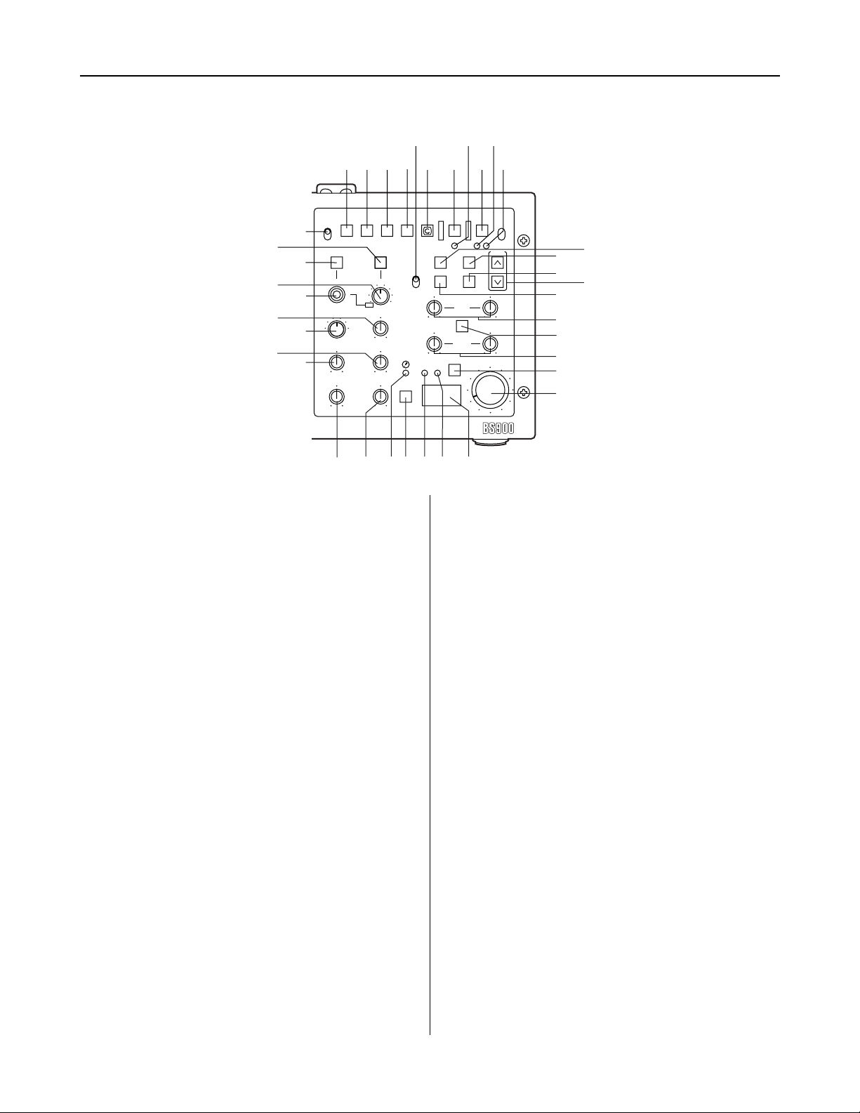
Parts and their functions
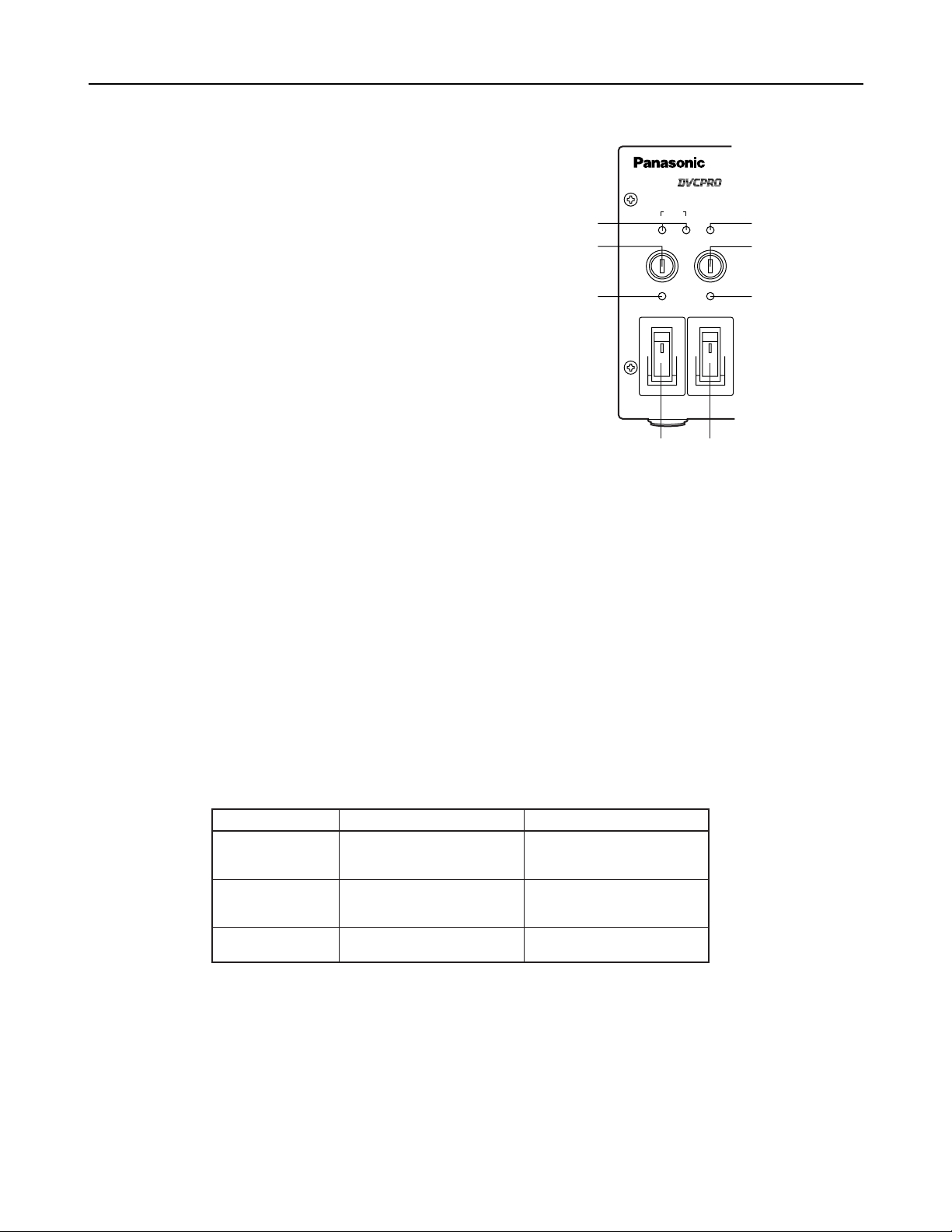
Front panel
CABLE
SHORT ALARM
FUSE
HEAD POWER
ON
OFF
MAIN
ON
OFF
FUSE
OPEN
DIGITAL TRIAX
1
2
4
5
6
3
7
8
400V 1A
250V T 2.5A L
5
Power fuse (FUSE)
This is the main power supply fuse of the AJ-BS900P. Use a dedicated DC fuse (400V 1A) which can withstand inrush.
6
Camera AC power fuse (FUSE)
This is the fuse of the power supply to the camera head. Use a dedicated DC fuse (400V 1A) which can withstand inrush.
7
CABLE indicators
These indicators show the status of the camera cable.
OPEN: Indicates that the camera cable is open. (In cases where, for instance, a connector has become disconnected or a wire
has broken.) The power supply to the camera is off when this indicator is lit.
SHORT: Indicates that the camera cable is shorted. The power supply to the camera is off when this indicator is lit. If the
SHORT indicator lights, the cable needs to be inspected.
8
ALARM indicator
This indicator blinks when a problem has occurred. If a monitor has been connected to PIX OUT, letters representing the alarm
concerned will be displayed on the monitor simultaneously. For further details, refer to the table below.
1
MAIN switch
This is the on/off switch for the main power supply.
This switch operates only when the unit is operated on AC
power. It does not work when it is operated on DC power.
<Note>
When DC power is supplied, whether the switch is ON or
OFF depends on whether the main power switch on the DC
power supply is ON or OFF.
2
HEAD POWER switch
This is the on/off switch for the power supply to the camera
head.
<Note>
This switch also supplies power to the AJ-RP900P
repeater.
3
MAIN power indicator
Lights when the main power supply is turned on.
4
Head power indicator
Lights when the power supply to the camera head (AJ-CA900P) is turned on.
ALARM LED status
Blinks rapidly
Blinks slowly
Lights
Description of alarm
The indicator lights when 11and
22
have occurred simultaneously.
11
The temperature inside the unit
is higher than the reference
value.
22
One or both fans have stopped
working because a problem
has occurred.
“TEMP HI!”
“FAN STOP!”
“TEMP HI & FAN STOP!”
Letters spelling out the alarm
- 4 -
=
MIC button
This button is used to switch the intercom microphone on and off. It has three positions: ON, OFF, and PTT. (PTT: Audio
transmission continues as long as the button is held down.)
<
INTERCOM level knob
This knob is used to adjust the volume of the microphone
input to the intercom.
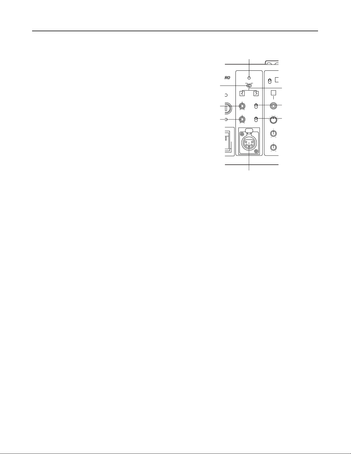
Parts and their functions
Front panel
GENLOCK
VTR
ENABLE
REW
SET UP
MON SEL
KNEE
POINT
KNEE
SLOPE
ON
OFF
(PUSH)
OFFSC H
PHASE
INTERCOM
PGM
ON
OFF
PTT
MIC
PRIVATE
SYSTEM
PUSH
PHASE
ON
OFF
R
G
B SUP
RIAX
9
:
;
<
?
@
>
=
9
Intercom XLR connector
This is used to connect a headset to the intercom.
:
PGM level knob
This knob is used to adjust the volume of the PGM audio
mixed into the signal fed to the intercom headset.
?
Phase adjustment buttons
These buttons are used to adjust the phase selected using the phase adjustment switch >.
;
SYSTEM/PRIVATE selector switch
This is used to toggle the intercom between the system and
private modes.
SYSTEM: The intercom is connected to the system via the
communication connector on the rear panel of
the unit.
PRIVATE:The intercom is not connected to the system via
the communication connector on the rear panel
of the unit.
>
Phase adjustment switch
The available settings are SC PHASE, OFF, and H PHASE.
SC PHASE: Selects SC phase adjustment.
OFF: No phase adjustment is performed.
H PHASE: Selects H phase adjustment.
@
GEN LOCK indicator
This indicator lights when the camera’s synchronization is locked using the signal input via the GEN LOCK connectors on the
rear panel.
<Note>
This indicator blinks if there is something wrong with the GEN LOCK signal. When this happens check the GENLOCK signals.
- 5 -
Parts and their functions
M
AWB button
This is the auto white balance button. It does not work
when the L WHITE BAL switch is set to the PRST
position.
Button LED lit: Auto white balance in progress.
Button LED dark: Auto white balance completed.
Button LED stops blinking and goes off: Auto white balance
error.
N
ABB button
This is the auto black balance button.
Button LED lit: Auto black balance in progress.
Button LED dark: Auto black balance completed.
Button LED stops blinking and goes off: Auto white balance
error.
O
BAR switch
This switch is used to output a bar signal from the AJBS900P. The camera head does not switch to bar mode.
H
VTR WARNING indicator
This indicator lights when a VTR operation error occurs.
I
CALL button
This button is used to call the camera. This button’s LED
lights when a call is made from the camera.
K
R TALLY indicator
This indicator lights when an R tally signal is being input via
the TALLY IN connector.
J
G TALLY indicator
This indicator lights when a G tally signal is being input via
the TALLY IN connector.
Front panel
L
WHITE BAL (white balance selector) switch
PRST: This position should be selected when there is no
time to adjust the white balance. It uses the 3200
K white balance value stored in memory.
A or B: The white balance memory is set to A or B.
VTR
ENABLE
WHITE
BAL
REW
Base Station AJ-
FF STOP
SHUTTERSET UP
PIX SEL
KNEE
POINT
KNEE
SLOPE
GAMMA
DETAIL
M.PED
PLAY
AWB
CHECK
AUTO IRIS
IRIS
BR
GAIN
FILTER
ABB
BAR
ENABLE
PAINTING
GAIN
AUTO KNEE
GAIN
REC CHK
START / STOP
CALL
TALLY
VTR WARNING
ON
OFF
(PUSH)
PRST
A
B
BLACK
RGENG
SEQ
B SUP
S.V
S.S.
100(60)
1000
120
250
500
2000
^
A
BEC
DFG
_
H
J
I
K
L
N
O
M
R
S
T
U
V
W
X
YZ[
\
]
`
a
b
c
d
Q
P
e
6
5
ª
1
B
REW button
This is the rewind button for the VTR.
C
FF button
This is the fast forward button for the VTR.
D
STOP button
This is the stop button for the VTR.
E
PLAY button
This is the play button for the VTR.
F
REC CHK button
This button is used to display the recording status of the
VTR.
G
START/STOP button
This button is used to turn the VTR’s recording operation
on and off.
A
VTR ENABLE button
This button is used to operate the VTR from the base
station.
ON: Activates VTR operation using the controls on the
front panel (buttons B to G). The time code is
displayed at PIX OUT.
OFF: Deactivates VTR operation using the controls on the
front panel. The time code is not displayed at PIX
OUT.
<Note>
The VTR’s playback video signal is not output from the
base station.

- 6 -
Parts and their functions
Front panel
a
MONI SEL switch
This switch is used to switch the signals output from the
PIX and WFM jacks on the rear panel of the AJ-BS900P.
_
KNEE POINT knob
This knob is used to set the manual knee point.
`
DETAIL knob
This knob allows adjustment of the master DETAIL setting.
^
GAMMA knob
This knob is used to change the camera’s master gamma
setting.
b
SET UP button
This button is used to make camera settings.
When it is lighted, menus are displayed at PIX OUT.
c
SET UP dial
This dial is used to select settings on the setting menus.
After selecting the desired setting by turning the dial, press
to enter it.
Menu settings can be performed when the b SET UP
button is lighted.
When the b SET UP button is not lighted, the SYNCHRO
SCAN speed can be set; when SYNCHRO SCAN is
selected.
e
Shutter speed selector switch
This switch is used to select the shutter speed. The
available settings are SYNCRO SCAN Super V and 1/100
to 1/2000.
Moving the switch when the SHUTTER button is in the off
position will not cause the shutter to operate.
d
SHUTTER button
This button activates the operation performed using the
shutter speed selector switch e. It should be put into the
on position when using an electronic shutter.
[
! indicator
This lights when the lens extenders (x2) are used with the
camera.
]
KNEE SLOPE knob
This knob is used to set the manual knee slope.
R
PAINTING ENABLE button
This button is used to enable painting (gain knob S and
black knob T) operation.
V
AUTO IRIS button
This button is used to toggle auto iris operation on and off.
Lit: Auto iris operation on.
Dark: Auto iris operation off.
W
LED digital indicator
This indicator displays the F value of the lens.
When changes are made to the gain or filter settings, the
corresponding values are displayed for about two seconds.
Also, pressing the CHECK button Z toggles the display in
sequence among the gain, filter, and F values.
<Note>
“---” appears when the camera recorder’s power is OFF.
U
IRIS knob
When the AUTO IRIS button V is in the on position, the
value selected using this knob is added or subtracted to the
IRIS LEVEL setting in the USER MENU.
When the AUTO IRIS button V is in the off position, this
knob is used to perform adjustment of the iris setting.
<Note>
Set the lens manual/auto selector switch to AUTO.
Y
FILTER indicator
This indicator lights when the filter position is shown by the
LED digital indicator.
X
GAIN indicator
This indicator lights when the gain value is shown by the
LED digital indicator.
\
M PED knob
This knob is used to adjust the master pedestal setting.
Z
CHECK button
Pressing this button multiple times causes first the GAIN
indicator and then the FILTER indicator to light. When the
GAIN indicator is lit the LED digital indicator shows the filter
position, and when the FILTER indicator is lit the LED
digital indicator shows the gain value.
S
GAIN knobs
These are the R and B gain adjustment knobs.
T
BLACK knobs
These are the R and B pedestal adjustment knobs.
P
AUTO KNEE button
This button is used to toggle auto knee operation on and
off.
Lit: Auto knee operation on.
Dark: Auto knee operation off.
Q
GAIN buttons
These buttons are used to switch the camera’s gain setting.
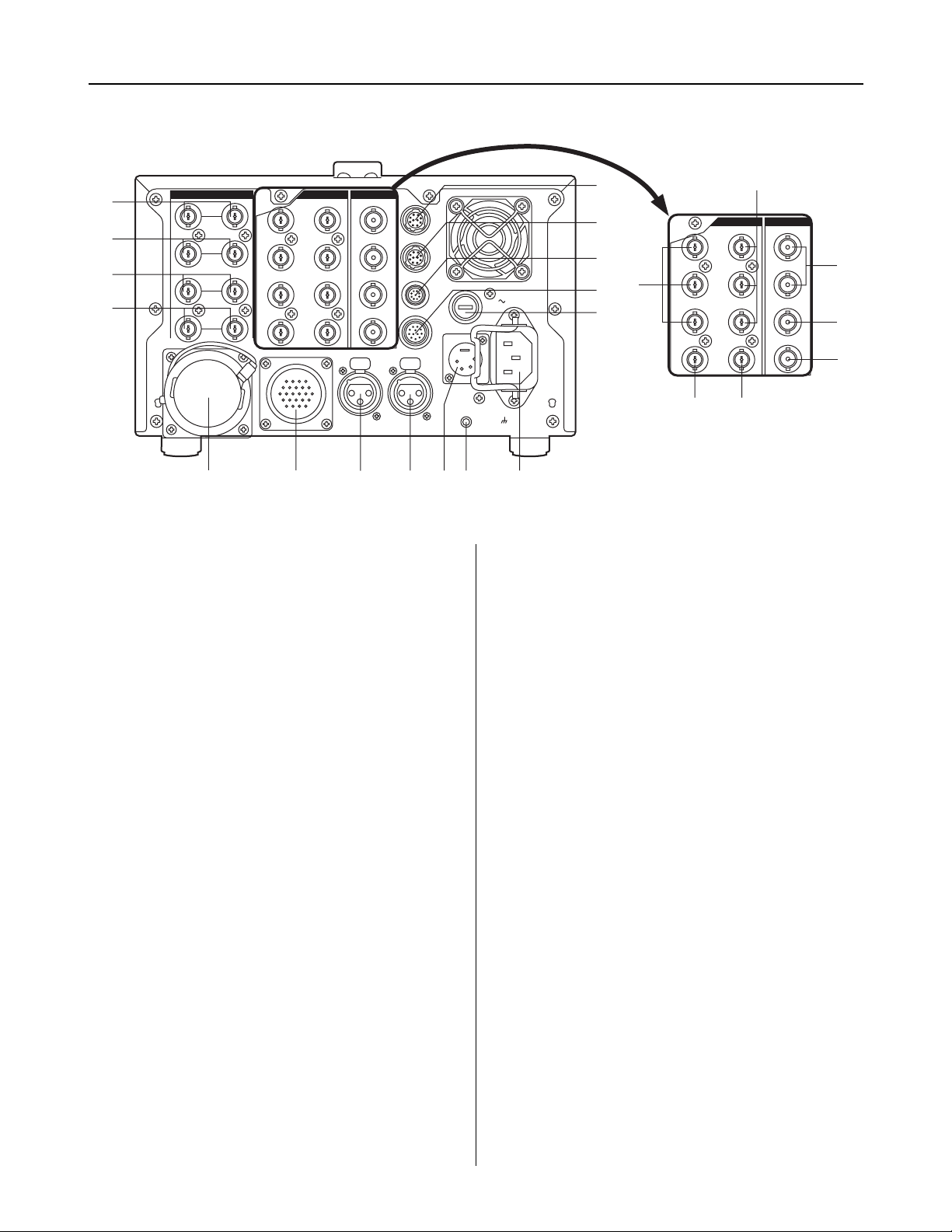
- 7 -
Parts and their functions
EXT DC IN
GEN–
LOCK
ENC
1
ENC
2
ENC
3
PIX
Y/G
4:2:2
4:2:2
SDI OUTOUTIN
OP4
OP3
WFM
TALLY
FUSE 400V 15A
SIGNAL
GND
AC IN
AUDIO
OUT
CH 1
PUSH
CH 2
PUSH
COMMUNICATION
PB/B
PR/R
WFM
RET 1
RET 2
PROMPT
1
2
3
4
5
7689
:
;
=
>
<
?
@
A
B
C
D
E
ENC
1
ENC
2
ENC
3
PIX
Y/G
4:2:2
4:2:2
SDI OUTOUT
PB/B
PR/R
WFM
OP1
OP2
G
F
OP1
OP2
Rear panel
1
GEN LOCK connectors
These are the standard external signal input connectors
used when locking the camera’s synchronization to an
external sync signal.
2
RET 1 connectors
These are the input connectors for return signal 1, which is
sent to the camera.
6
COMMUNICATION connector
This connector is used for making connections to an
intercom system. The supports types of intercom system
are 2W, 4W, and RTS. Use the switch on the BS AUDIO
board to select the system. For details, refer to “Switches”
(page 17).
7
AUDIO CH1 connector
This is the output connection for the camcorder’s MIC CH1
signal.
3
RET 2 connectors
These are the input connectors for return signal 2, which is
sent to the camera.
4
PROMPT connectors
These are the input connectors for the teleprompter signal,
which is sent to the camera.
5
Triax connector
This is the triax connector used for making connections to
the AJ-CA900P.
8
AUDIO CH2 connector
This is the output connection for the camcorder’s MIC CH2
signal.
9
DC 12V IN (external power supply input) jack
This jack is used to connect an external battery for use as a
power supply.
<Note>
Use the AJ-B95 AC adapter (12V, 13A), available as an
optional accessory, for the DC power.
<
OP3 connector
This connector is for making connections to an extension
control unit (ECU) or remote control operation panel
(RCOP). The compatible ECU model is the AJ-EC3P.
However, the RCOP cable is required for connection. For
further details, consult your dealer.
=
OP4 connector
This connector is for making connections to the camera
select unit (CSU) of a master control panel (MCP). The AJBS900P is not compatible with any currently available
CSUs. Plans call for a compatible model to be developed
in future.
>
WFM control connector
This is an output connection used for waveform monitoring.
One-waveform, two-waveform, and three-waveform control
are supported.
:
GND terminal
This terminal is used to ground the AJ-BS900P.
;
Power connector
This connector is used to supply power to the AJ-BS900P.

- 8 -
Parts and their functions
Rear panel
?
TALLY connector
This is the connector for the R tally and G tally signals. It
can be used for PM tally.
@
DC power fuse (FUSE)
This fuse is for the AJ-BS900P’s DC power supply. Use a
dedicated DC fuse (400V 15A) which can withstand inrush.
A
4 : 2 : 2 connectors
These connectors are for component serial digital output.
They are activated if the AJ-YA901P option board is
installed. One component may be connected to each
output BNC connector. The output signals comply with the
SMPTE259M-C standard.
B
Y/G, PB/B, and PB/R connectors
These output connectors are for component signals or
RGB signals. Use the switch on the BS DIGITAL board to
select the system. For details, refer to “Switches” (pages
18).
C
Video output connectors
These are output connectors for component video signals.
D
PIX output connector
This is the output connector for the picture monitor signal.
Signal switching is performed using the PIX SEL switch.
E
WFM output connector
This is the output connector for the waveform monitor
signal. Signal switching is performed using the MONI SEL
switch.
F
OP1 connector
This connector is not used on the current version of the AJBS900P.
G
OP2 connector
This connector is not used on the current version of the AJBS900P.
- 9 -
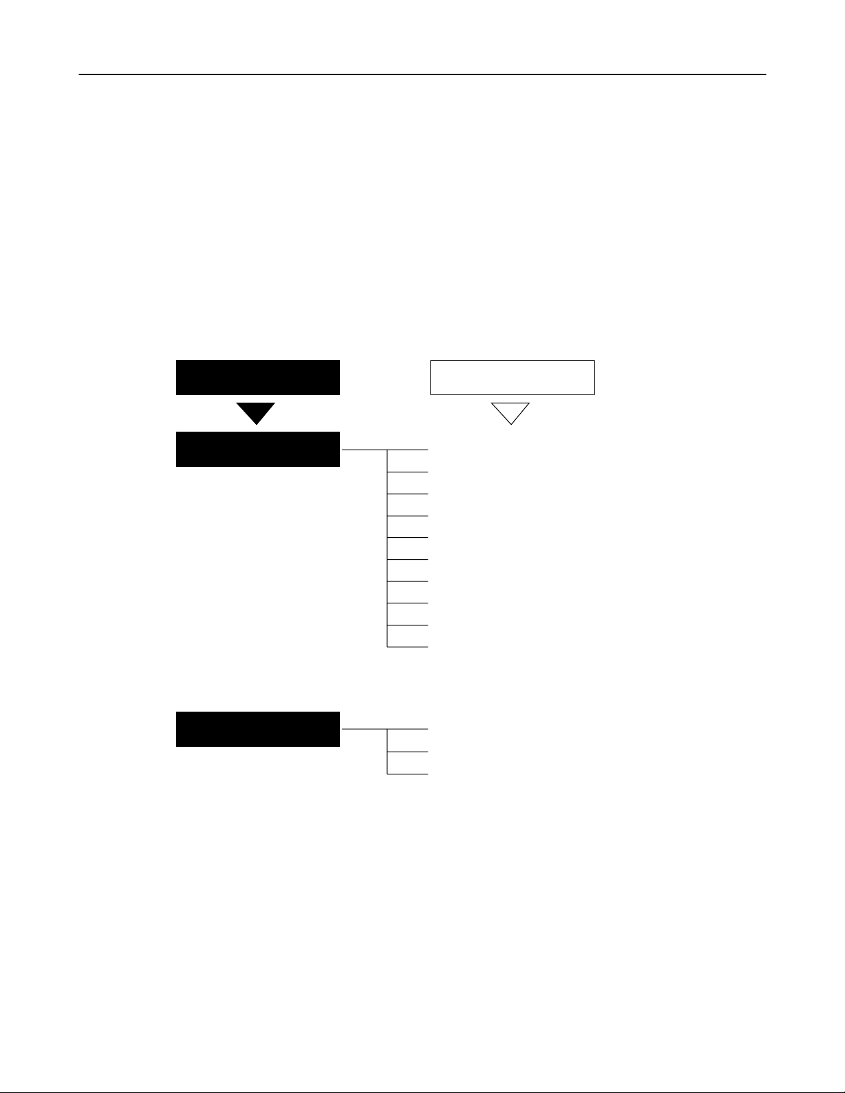
PIX output menu indications
PIX output setting menu indications
When the SET UP button is pressed so that it lights, setting menu indications are output via the PIX output connector.
The setting menus consist of main menus and submenus. Setting menus are displays one page at a time. All of the
setting menu screens and their structure are shown in the diagram below.
The MAIN MENU consists of two screens, 1/2 and 2/2. These screens are used to open the submenus.
To open a submenu, select it by turning the SET UP dial and then press the SET UP dial.
To return to the MAIN MENU from a submenu, turn the SET UP dial to align the arrow cursor with the desired menu
title, then press the SET UP dial.
For details on the submenu items, refer to the Instruction Manual of the camera recorder used.
Structure of setting menus
MAIN MENUS
MAIN MENU 1/2
MAIN MENU 2/2
SUB MENUS
1 SYNCHRO SCAN
2 VR DATA
3 MATRIX
4 DTL SETTING
5 ADDITIONAL DTL
6 SKIN TONE DTL
7 KNEE / LEVEL
8 FLARE / GAMMA
9 GENLOCK / IRIS
: CAMERA SW MODE
; CAMERA SETTING
< AUTO SHADING
= DIAGNOSTIC

- 10 -
MAIN MENU 1/2 screen
<Note>
The items on this menu cannot be set using the SET UP dial.
They are set using the controls on the front panel.
11
SYNCRO SCAN screen
This screen is used to make synchro scan settings.
# < SYNCHRO SCAN >
SYNCHRO SCAN : 1/60.8
22
VR DATA screen
This screen displays the setting values for the
adjustment knobs on the front panel.
# < VR DATA >
MASTER PED:+000
MASTER DTL:+00
MASTER GAMMA:0.45
KNEE POINT:090%
KNEE SLOPE:13
R GAIN
:
+000
B GAIN
:
+000
R PEDESTAL:+000
B PEDESTAL:+000
# < MATRIX >
MATRIX TABLE:A
MATRIX R-G:+00
MATRIX R-B:+00
MATRIX G-R:+00
MATRIX G-B:+00
MATRIX B-R:+00
MATRIX B-G
:
+00
33
MATRIX screen
This screen is used to select the camera’s matrix
settings.
44
DTL SETTING screen
This screen is used to make detail settings.
# < DTL SETTING >
H.DTL LEVEL:06
D.DTL LEVEL
:
13
DTL CORING:03
H.DTL FREQ.:04
DARK DTL
:
00
LEVEL DEPEND.:00
BLACK STRETCH:OFF
MATRIX TABLE:OFF
# < ADDITIONAL DTL >
C DTL COMPE.:OFF
CHROMA DTL:0
KNEE APERTURE:ON
SLIM DTL
:
OFF
CORNER DTL
:
OFF
DTL GAIN(+)
:
+00
DTL GAIN(-)
:
+16
DTL CLIP
:
00
H.DTL LINE MIX:1H
55
ADDITIONAL DTL screen
This screen is used to select the camera’s special
detail settings.
66
SKIN TONE DTL screen
This screen is used to select the camera’s skin tone
detail settings.
# < SKIN TONE DTL >
SKIN TONE DTL:OFF
SKIN TONE HUE:103
SKIN TONE LEVEL:25
SKIN TONE WIDTH:15
SKIN TONE CORING:05
SKIN TONE ZEBRA:OFF
<Note>
The SKIN TONE ZEBRA setting automatically switches to
OFF when the SKIN TONE DTL submenu is opened,
regardless of whether the previous setting was ON or OFF.

- 11 -
MAIN MENU 1/2 screen
# < FLARE / GAMMA >
R FLARE
:
000
G FLARE
:
000
B FLARE
:
000
R GAMMA
:
+00
B GAMMA
:
+00
88
FLARE/GAMMA screen
This screen is used to select the camera’s flare and
gamma settings.
77
KNEE/LEVEL screen
This screen is used to select the camera’s setup
level settings.
# < KNEE / LEVEL >
MANUAL KNEE:ON
WHITE CLIP:ON
WHITE CLIP LVL:110%
AUTO KNEE POINT:085
AUTO KNEE LVL:110
SET UP
:
0%
<Note>
The SET UP items on this menu cannot be set using the SET
UP dial. The camera setting statuses are simply displayed
here.
# < GENLOCK / IRIS >
A.IRIS LEVEL:045
A.IRIS PEAK/AVE:050
A.IRIS MODE
:
NORM1
H PHASE COARSE:07
H PHASE FINE:128
SC PHASE COARSE:0
SC PHASE FINE
:
128
99
GENLOCK/IRIS screen
This screen is used to control the genlock and iris
functions.
<Note>
The H PHASE and SC PHASE items on this menu cannot be
set using the SET UP dial. Use the buttons on the front panel
instead.
# < CAMERA SW MODE >
SUPER V MODE:FRM1
FILTER INH
:
ON
SHOCKLESS AWB:NORMAL
::
CAMERA SW MODE screen
This screen is used to select the camera’s switch
mode settings.

- 12 -
MAIN MENU 2/2 screen
==
DIAGNOSTIC screen
This screen is displays the software version.
# < DIAGNOSTIC >
VERSION
:
Ver<¢.¢.¢>
UP DATE
:
¢¢¢¢.¢¢.¢¢
# < CAMERA SETTING >
DETAIL
:
ON
2D LPF
:
OFF
SUPER COLOR:ON
GAMMA
:
ON
TEST SAW
:
OFF
FLARE
:
ON
H-F COMPE.
:
ON
NEGATIVE DTL:OFF
;;
CAMERA SETTING screen
This screen is used to select the camera’s basic
settings.
<<
AUTO SHADING screen
The AUTO SHADING settings are performed on
this screen. For further details, refer to the section
entitled “Shading adjustments” (page 13).
# < AUTO SHADING >
BLACK
WHITE
BLACK COMPE.:ON
WHITE COMPE.:ON

- 13 -
Shading adjustment
When the BLACK or WHITE (V.SAW) setting on the AUTO SHADING menu or the WHITE (DIGITAL) setting on the WHITE
SHADING menu is selected to perform shading, menus similar to those shown below appear. The operation procedure is illustrated
below using black shading as an example.
Shading menu operation procedure (example: black shading)
# < AUTO SHADING >
BLACK
WHITE
BLACK COMPE.
:
ON
WHITE COMPE.:ON
ACTIVE OK?
YES
# NO
From MAIN MENU 2/2, select the AUTO SHADING submenu.
Align the arrow cursor with the BLACK item and press the SET UP dial. A
page confirming whether or not you want to perform shading adjustment
appears.
To perform shading adjustment, align the arrow cursor with YES and press the
SET UP dial. (After this, the indication “SHADING ACTIVE” appears in the
center of the screen.) If you do not wish to perform shading adjustment, align
the arrow cursor with NO and press the SET UP dial. The AUTO SHADING
page reappears.
The AUTO SHADING page reappears automatically when shading adjustment
completes.
This concludes the shading adjustment procedure.
–
Confirmation page
–
1.
2.
3.
4.
 Loading...