

Page 1
AHR5
11/2002
The AHR5 switch with actuating
lever and retainer assembled
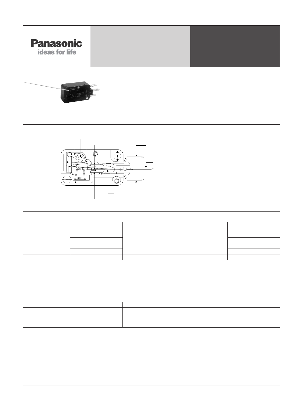
CONSTRUCTION
Rotating
shaft
Handle
Pin
plunger
HIGH CONTACT PRESSURE
WITH LIGHT OPERATING
ACTION
FEATURES
• High contact pressure with light operating action
• Easy installation of the lever—Tools
or adhesives are unnecessary for attaching the actuating lever
• Low-level circuit type is also available
Actuating spring
Movable contact
Solder and
Q.C. (187)
N.O. terminal
Common
terminal
V-ROTARY
ACTION (AHR5)
SWITCHES
TYPICAL
APPLICATIONS
• Vending machines
Restoration
spring
Stationary
contact
Operating spring
N.C. terminal
PRODUCT TYPES
Type Retainer mounting direction Operating force (max.) Release force (min.)
Standard (Silver alloy)
Low-level circuit type
(Gold clad)
Actuator lever 52.3mm 2.059inch — AHR5801
Remarks: 1. The retainer is provided with the switch body without assembled.
2. Actuating levers are available separately.
(AHR5801, length: 52.3mm 2.059inch)
3. As for International standard, please refer to the “Information”.
Counter-clockwise
Clockwise AHR5411
Counter-clockwise AHR540161
Clockwise AHR541161
0.1N•cm {10.2gf•cm} 0.013N•cm {1.3gf•cm}
SPDT .187 Quick-connect/
solder terminal
AHR5401
SPECIFICATIONS
1. Contact rating (Resistive load)
Type Standard rating Low-level rating
Standard (Silver alloy) 5A 250V AC
Low-level circuit type (Gold clad) 1A 250V AC
6V DC 5mA
12V DC 2mA
24V DC 1mA
75
Page 2
AHR5
11/2002
2. Characteristics
Type Standard type Low-level circuit type
Expected life
(min. operations)
Mechanical (at O.T. rated)
Electrical (at O.T. max.)
Insulation resistance Min. 100MΩ (at 500V DC insulation resistor meter)
Between terminals 600 Vrms for 1 min.
Between terminals and
Dielectric strength
other exposed metal parts
Between terminals and
ground
Contact resistance (initial)
(by voltage drop at 1A 6 to 8V DC)
Max. 50mΩ
Vibration resistance (pin plunger) 10 to 55 Hz at amplitude 0.75mm (Contact opening: max. 1msec.)
Shock resistance (pin plunger)
Allowable operating speed 1 to 100°/sec.
Max. operating cycle rate 240
Ambient temperature –25°C to +65°C –13°F to +149°F (no freezing below 0°C)
Ambient humidity Max. 85% R.H.
Unit weight 7g .25oz
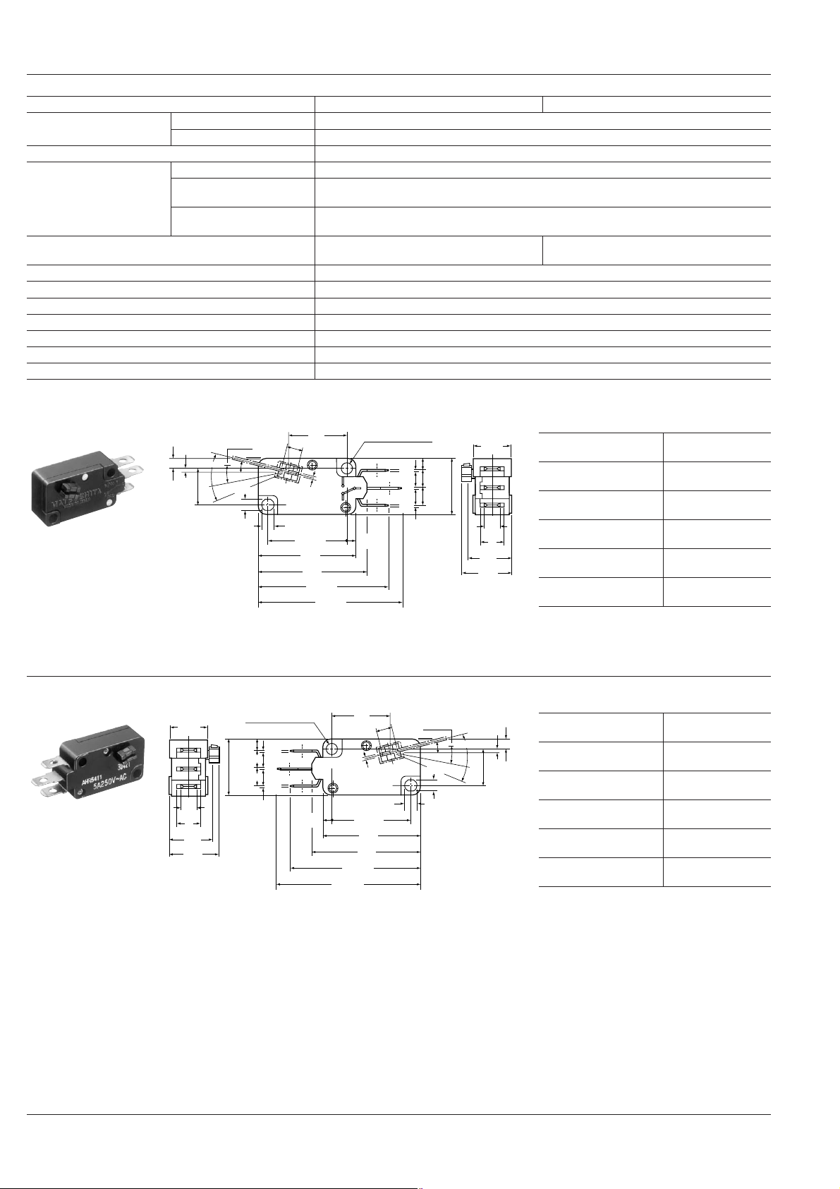
DIMENSIONS
(Counterclockwise)
2.8
.110
10.3
.406
1.0
.039
±0.1
±.004
P.T.
25° max.
M.D.
15° max.
F.P.15°
O.T.13° min
+0.25
3.1
–0.05
+.010
.122
–.002
16.6
.654
4.6
±5°
.181
NO
0.75
.030
2
±0.15
3.4
±.006
.134
±0.1
22.2
±.004
.874
27.8
1.095
31
1.221
±0.8
37
±.032
1.457
±0.8
41
±.032
1.614
+0.25
3.1 DIA. HOLE
–0.05
+.010
.122 DIA. HOLE
–.002
1
3
NC
2.8
.110
.020
.020
.020
±0.8
2.9
±.032
.114
0.5
±0.8
5.2
±.032
.205
0.5
±0.8
5.2
±.032
.205
0.5
15.9
.626
6
10
(at 60 cpm)
4
(at 20 cpm)
5 × 10
2,000 Vrms for 1 min.
2,000 Vrms for 1 min.
(by voltage drop at 0.1A 6 to 8V DC)
2
294m/s
{30G}
10.3
.406
Operating force, Max.
(Initial value)
Release force, Min.
(Initial value)
Pretravel
(Initial value)
Movement differential
(Initial value)
Overtravel
(Initial value)
Free position
.236
11.7
.461
13.7
.539
4.75
.187
6
(Initial value)
Max. 50mΩ
mm inch TORERANCE: ±0.4 ±.016
15°±5° (From the
horizontal axis)
0.1 N·cm
{10.2 g·cm}
0.013 N·cm
{1.3g·cm}
25° max.
15° max.
13° min.
(Clockwise)
10.3
.406
4.75
.187
.236
11.7
.461
13.7
.539
+0.25
3.1 DIA. HOLE
–0.05
+.010
.122 DIA. HOLE
–.002
±0.8
2.9
±.032
.114
0.5
±0.8
.020
5.2
±.032
.205
0.5
±0.8
.020
5.2
±.032
.205
0.5
15.9
.626
6
.020
.110
2.8
41
1.614
37
1.457
±0.8
16.6
.654
22.2
.874
1.221
±.032
4.6
.181
0.75
.030
.134
27.8
1.095
31
±0.8
±.032
10.3
.406
1.0
.039
2.8
.110
Operating force, Max.
(Initial value)
Release force, Min.
±0.1
±.004
(Initial value)
Pretravel
(Initial value)
Movement differential
(Initial value)
Overtravel
(Initial value)
Free position
(Initial value)
0.1 N·cm
{10.2 g·cm}
0.013 N·cm
{1.3g·cm}
25° max.
15° max.
13° min.
15°±5° (From the
horizontal axis)
M.D.
15° max.
±5°
F.P.15°
±0.15
3.4
±.006
±0.1
±.004
O.T.13° min
+0.25
3.1
–0.05
+.010
.122
–.002
P.T. 25° max.
76
Page 3

NOTES
11/2002
1. Method of attaching actuating lever
Insert tha lever in the rotating spindle,
then place the retainer over the spindle to
lock the lever in place as shown in Fig. 1.
Be sure that the retainer has snapped
over the lugs on the rotating spindle, with
the lugs entering fully into the holes in the
retainer.
Retainer
Hole (2 places)
Actuating lever
Rotating spindle
Lug section (2 places)
2. Regarding the actuating lever
As an accessory, the standard lever
(Product No. AHR5801) is available separately.
0.7 DIA. .028 DIA.
Stainless steel
90°
Standard lever
AHR5801
Less than
0.5R
.020R
1.2±0.2
.047±.008
52.3
2.059
At time of mounting,
50 mm from center of rotating spindle
3. Cautions regarding design of actuating lever
The dimensions of the lever at the mounting section are as shown in Fig. 2. These
dimensions should be used in the design
of an alternate actuating lever. The material can be stainless steel wire or piano
wire. The standard lever length is 50 mm
1.969 inch. A lever in excess of this length
would have a weight which could cause
erroneous operation.
d = 0.7±0.015 DIA.
d = .028±.001 DIA.
AHR5
4. Regarding switch mounting
Mount the switch to a smooth surface using M3 screws. Tighten the screw with 3 to
5 kg-cm torque. To prevent loosening of
the mounting screws, it is recommended
that spring washers be used in combination with adhesive material for locking the
screws.
In the mounted condition, the insulating
distance between each terminal and
ground should be checked for assurance
of proper distance.
5. Regarding changes in operating
characteristics
When selecting the V rotary action switch,
allow ±20% to the rated operating and release forces.
(Example)
OF: 10.2 g-cm max. specification
10.2 × (100+20%) = 12.24 g-cm
RF: 1.3 g-cm min. specification
1.3 g-cm × (100–20%) = 1.04 g-cm
6. Adjustment of the operating object
The positioning of the operating object
should be such that when direct force is
not applied to the actuator, the actuator is
in its free position. The operating object
should apply force in the operating direction. The standard value of overtravel to
be used should be set within the range of
70% to 100% of the rated O.T. value. Furthermore, if the operating position limit is
exceeded, the electrical and mechanical
life of the switch will be shortened.
7. Avoid using V Rotary switches in the
following conditions:
• Where the ambient temperature exceeds the range of –25°C to +65°C –13°F
to +149°F.
• Where the relative humidity exceeds
85%.
• Where the permissible operating speed
of 1 to 100°/sec. is exceed.
• Where the operating speed of 240 cpm.
is exceeded.
• Where the lever length of 50mm
1.969inch is exceeded.
77
 Loading...