

Page 1
POWER
/I
VCR
EJECT
OPEN
/
C
L
O
SE
PULL -OPEN
STOP
/ REW
FF /
PICT
U
RE
MO
DE
T
IM
ER
CH
E
CK
PROG
RE
SS
IV
E O
U
T
S
T
OP
RE
C
CHECK
M
US
I
C
WITH
PICT
U
RE
PL
AY
PLAY
D
V
D
Operating
AG- P
Instructions
Model No.
DVD Player/Video Cassette Recorder
Before attempting to connect, operate or adjust this product, please read these instructions completely.
/
VQT0C73
Page 2

Contents
Before Use
Dear Customer............................................................................ 3
Accessories .................................................................................. 3
Usage Precautions ..................................................................... 5
Video deck and cassette tape information............................... 5
Disc information ......................................................................... 6
Control reference guide ............................................................. 7
FRONT ........................................................................................ 7
REAR............................................................................................ 7
The unit’s display .......................................................................... 8
Infra-red Remote Controller.......................................................... 9
The remote control ................................................................... 11
Installing the Batteries ................................................................ 11
Use ............................................................................................. 11
Connections.............................................................................. 12
Basic Connections ...................................................................... 12
Connection to a TV using the Audio/Video Input Sockets .......... 12
To enjoy DVD video with a higher image quality ........................ 13
Cable Connection ..................................................................... 14
Tuning the TV to your unit....................................................... 15
Plug in Auto Tuning .................................................................... 15
VCR
VCR Playback............................................................................ 17
Basic Playback ........................................................................... 17
Other Playback Functions........................................................... 18
Tracking Adjustment and Vertical Locking Adjustment............... 19
Manual Recording..................................................................... 20
One-Touch Recording (OTR) ..................................................... 21
Timer Recording ....................................................................... 22
To Program with
the On Screen Display (OSD) .................................................. 22
Search Functions...................................................................... 24
Jet Navigator............................................................................... 24
To Check the Recorded Programming Data
(Time Stamp Function)............................................................. 26
To Find the Beginning of Each Recording
(VHS Index Search System) .................................................... 26
Searching while checking the video cassette contents
(Intro-Jet Scan) ........................................................................ 27
Other Functions........................................................................ 27
To Delete all of a Cassette’s Contents
(Tape Refresh Function) .......................................................... 27
Settings Using the On Screen Display ................................... 28
Common procedure .................................................................... 28
To Select the Desired Language ................................................ 28
Setting the Clock of your unit...................................................... 28
Channel Set ................................................................................ 29
Option ......................................................................................... 30
Onscreen display ........................................................................ 31
Changing audio........................................................................... 31
DVD
Playing discs.............................................................................32
Basic play....................................................................................32
Starting play from where you stopped it...................................... 33
To immediately access a specific scene or track ........................ 34
Other methods of play..............................................................35
Playing the programs or play lists on DVD-RAM ...................37
Selecting a program to play
(Direct Navigator) .....................................................................37
To play back favorite scenes only (Play lists) .............................37
MP3/WMA and CD text navigating menus.............................38
To get more enjoyment from movies and music ................... 40
To switch subtitle, audio or angle-view .......................................40
To change the settings in accordance with the software ............41
Using On-Screen Menu Icons ..................................................43
Common procedures...................................................................43
Disc information ..........................................................................44
Progress indicator.......................................................................44
Unit information...........................................................................45
Enjoying more powerful sound ...............................................47
To connect to external audio devices..........................................47
Changing settings.....................................................................48
Common procedures...................................................................48
SET UP menus ...........................................................................49
Quick Setup................................................................................. 50
Entering a password (Ratings)....................................................51
Digital output ...............................................................................51
Others
Editing........................................................................................52
Assemble Editing ........................................................................52
Adding Music to Video
(MUSIC WITH PICTURE)......................................................... 53
Helpful Hints
Error Messages .........................................................................54
On Screen Display ...................................................................... 54
Self-diagnostic Indications ..........................................................54
Before Requesting Service ......................................................55
Glossary.....................................................................................58
Q&A ............................................................................................60
Specifications............................................................................61
Index...........................................................................................63
2
Page 3
Dear Customer
Thank you for purchasing this product.
For optimum performance and safety, please read these
instructions carefully.
≥Operations in these instructions are described mainly
with the remote control, but you can do the operations
on the main unit if the controls are the same.
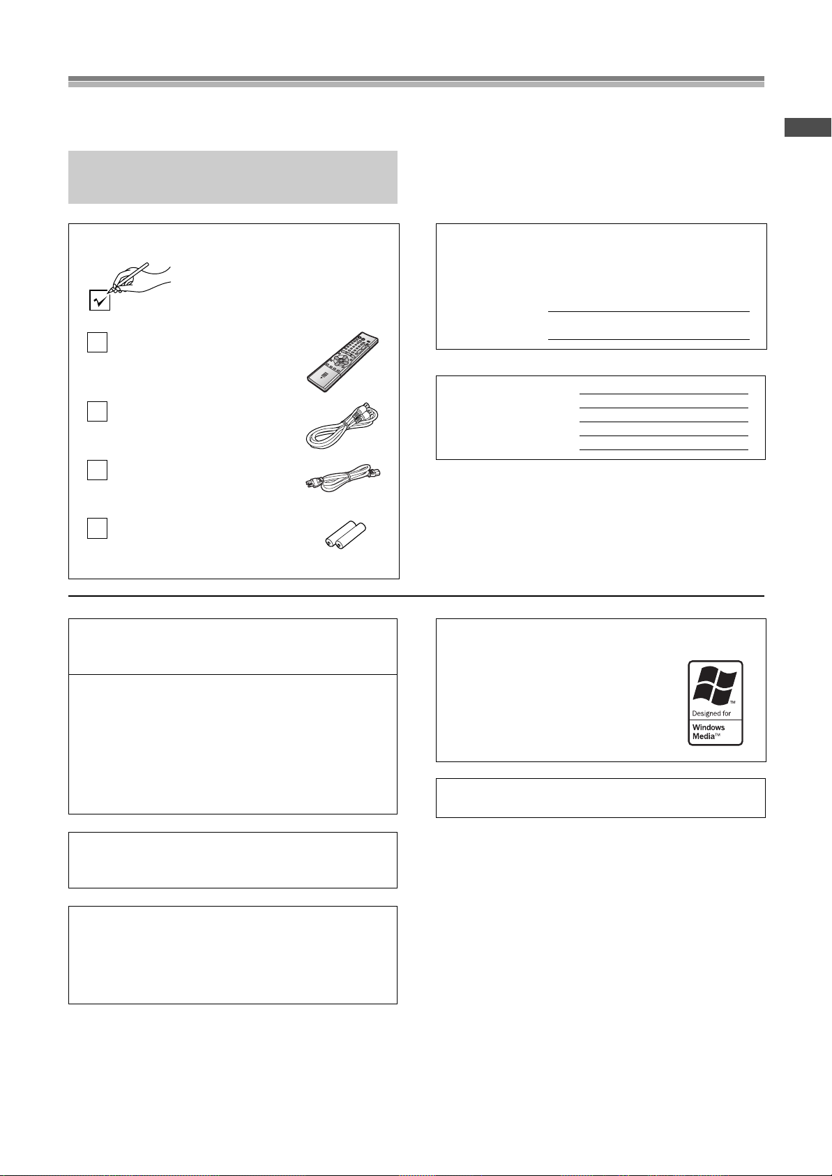
Accessories
Please check and identify the supplied
accessories. Use numbers indicated in
parentheses when asking for
replacement parts.
1 pc. Infrared Remote Controller
(EUR7615LB0)
1 pc. Coaxial Cable
1 pc. AC Power Cord
2 pcs. “R6” size Batteries
Apparatus Claims of U.S. Patent Nos. 4,631,603,
4,577,216, and 4,819,098, licensed for limited viewing uses
only.
This product incorporates copyright protection technology
that is protected by method claims of certain U.S. patents
and other intellectual property rights owned by Macrovision
Corporation and other rights owners. Use of this copyright
protection technology must be authorized by Macrovision
Corporation, and is intended for home and other limited
viewing uses only unless otherwise authorized by
Macrovision Corporation. Reverse engineering or
disassembly is prohibited.
The model number and serial number of this product can be
found on either the back or the bottom of the unit.
Please note them in the space provided below and keep for
future reference.
MO DEL NU MBE R
SERIAL NUMBE R
User memo:
DATE OF PURCHASE
DEALER NAME
DEALER ADDRESS
TELEPHONE NUMBER
Windows Media, and the Windows logo are
trademarks, or registered trademarks of
Microsoft Corporation in the United States
and/or other countries.
WMA is a compression format developed by
Microsoft Corporation. It achieves the same
sound quality as MP3 with a file size that is
smaller than that of MP3.
MPEG Layer-3 audio decoding technology licensed from
Fraunhofer IIS and Thomson multimedia.
AG-VP300P
Before Use
Manufactured under license from Dolby Laboratories.
“Dolby” and the double-D symbol are trademarks of Dolby
Laboratories.
Manufactured under license from Digital Theater Systems,
Inc. US Pat. No. 5,451,942, 5,956,674, 5,974,380,
5,978,762 and other world-wide patents issued and
pending. “DTS” and “DTS Digital Surround” are registered
trademarks of Digital Theater Systems, Inc. Copyright 1996,
2000 Digital Theater Systems, Inc. All rights reserved.
3
Page 4
FCC NOTE:
CAUTION
RISK OF ELECTRIC SHOCK
DO NOT OPEN
CAUTION: TO REDUCE THE RISK OF ELECTRIC SHOCK,
DO NOT REMOVE COVER (OR BACK).
NO USER-SERVICEABLE PARTS INSIDE.
REFER SERVICING TO QUALIFIED SERVICE
PERSONNEL.
This equipment has been tested and found to comply with
Part 15 of the FCC Rules. These limits are designed to
provide reasonable protection against harmful interference in
a residential installation. This equipment generates, uses and
can radiate radio frequency energy and, if not installed and
used in accordance with the instructions, may cause harmful
interference to radio communications. If this equipment does
cause or receive interference, which can be determined by
turning equipment off and on, the user is encouraged to try to
correct the interference by one of the following measures:
• Reorient or relocate the receiving antenna.
• Increase the separation between the equipment and receiver.
• Connect the equipment into an outlet on a circuit different circuit
from that to which the receiver is connected.
• Consult the dealer or an experienced radio/TV technician for
help.
FCC Caution: To assure continued compliance, follow the
attached installation instructions and use only shielded
interface cables when connecting to peripheral devices.
Any changes or modifications not expressly approved by the
party responsible for compliance could void the user’s
authority to operate this equipment.
Trade Name: Panasonic
Model No.: AG-VP300P
Responsible Party:
Matsushita Electric Corporation of America
One Panasonic Way, Secaucus, NJ 07094
Support Contact:
Panasonic Broadcast & Television Systems Company 1-800524-1448
This device complies with Part 15 of the FCC Rules.
Operation is subject to the following two conditions:
(1)This device may not cause harmful interference, and
(2)this device must accept any interference received,
including interference that may cause undesired operation.
CAUTION!
DO NOT INSTALL, OR PLACE THIS UNIT, IN A
BOOKCASE, BUILT-IN CABINET OR IN ANOTHER
CONFINED SPACE. ENSURE THE UNIT IS WELL
VENTILATED. TO PREVENT RISK OF ELECTRIC
SHOCK OR FIRE HAZARD DUE TO OVERHEATING,
ENSURE THAT CURTAINS AND ANY OTHER
MATERIALS DO NOT OBSTRUCT THE VENTILATION
VENTS.
CAUTION!
THIS PRODUCT UTILIZES A LASER.
USE OF CONTROLS OR ADJUSTMENTS OR
PERFORMANCE OF PROCEDURES OTHER THAN
THOSE SPECIFIED HEREIN MAY RESULT IN
HAZARDOUS RADIATION EXPOSURE.
DO NOT OPEN COVERS AND DO NOT REPAIR
YOURSELF. REFER SERVICING TO QUALIFIED
PERSONNEL.
WARNING
TO REDUCE THE RISK OF FIRE, ELECTRIC SHOCK
OR PRODUCT DAMAGE, DO NOT EXPOSE THIS
EQUIPMENT TO RAIN, MOISTURE, DRIPPING OR
SPLASHING AND ENSURE THAT NO OBJECTS
FILLED WITH LIQUIDS, SUCH AS VASES, SHALL BE
PLACED ON THE EQUIPMENT.
TO REDUCE THE RISK OF FIRE, SHOCK HAZARD
AND ANNOYING INTERFERENCE, USE THE
RECOMMENDED ACCESSORIES ONLY.
-
VISIBLE AND INVISIBLE LASER RADIATION WHEN OPEN.
DANGER
AVOID DIRECT EXPOSURE TO BEAM.
-
VISIBLE AND INVISIBLE LASER RADIATION WHEN OPEN.
CAUTION
AVOID EXPOSURE TO BEAM.
-
RAYONNEMENT LASER VISIBLE ET INVISIBLE EN CAS D’OUVERTURE.
ATTENTION
EXPOSITION DANGEREUSE AU FAISCEAU.
-
SYNLIG OG USYNLIG LASERSTRÅLING VED ÅBNING.
ADVARSEL
UNDGÅ UDSÆTTELSE FOR STRÅLING.
-
AVATTAESSA OLET ALTTIINA NÄKYVÄÄ JA NÄKYMÄTÖN
VARO !
LASERSÄTEILYLLE. ÄLÄ KATSO SÄTEESEEN.
-
SYNLIG OCH OSYNLIG LASERSTRÅLNING NÄR DENNA DEL
VARNING
ÄR ÖPPNAD. BETRAKTA EJ STRÅLEN.
-
SYNLIG OG USYNLIG LASERSTRÅLING NÅR DEKSEL ÅPNES.
ADVARSEL
UNNGÅ EKSPONERING FOR STRÅLEN.
-
SICHTBARE UND UNSICHTBARE LASERSTRAHLUNG, WENN ABDECKUNG
VORSICHT
GEÖFFNET. NICHT DEM STRAHL AUSSETZEN.
-
-
(FDA 21 CFR)
(IEC60825-1)
RQLS0233
(Inside of product)
This symbol alerts the user that important
literature concerning the operation and
maintenance of this unit has been included.
Therefore, it should be read carefully in order to
avoid any problems.
This symbol warns the user that uninsulated
voltages within the unit may have sufficient
magnitude to cause electric shock. Therefore, it is
dangerous to make any kind of contact with any
inside part of this unit.
Note to CATV system installer:
This reminder is provided to call the CATV system installer’s
attention to Article 820-40 of the NEC that provides guidelines
for proper grounding and, in particular, specifies that the cable
ground shall be connected to the grounding system of the
building; as close to the point of cable entry as practical.
4
Page 5
Usage Precautions
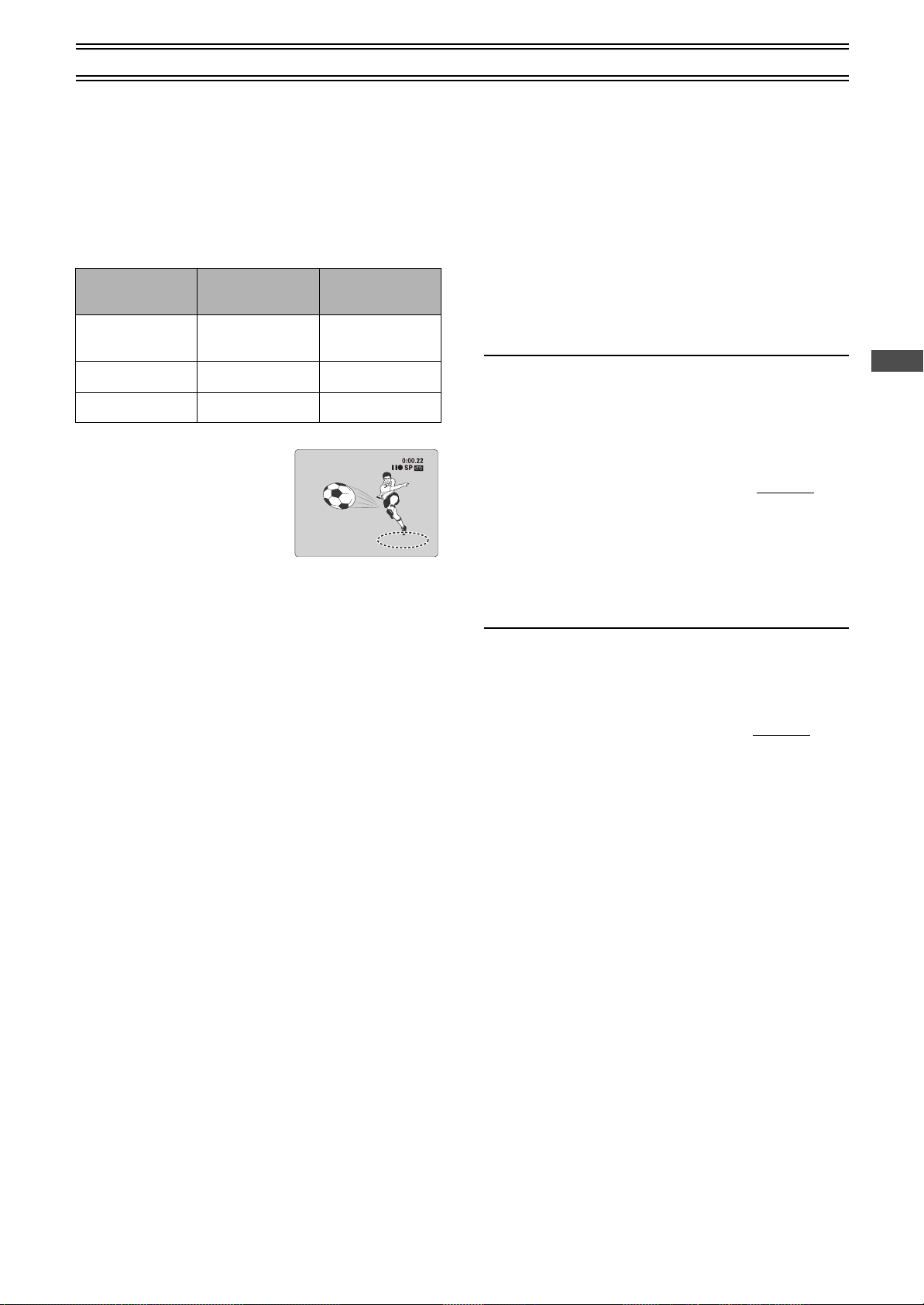
Tab
Normal picture Small amount of dirt Large amount of dirt
Please read these precautions before you operate this unit.
ªAvoid Sudden Changes in Temperature
If this unit is suddenly moved from a cold to a warm place,
dew may form on the tape and inside this unit.
ªHumidity and Dust
Avoid places where there is high humidity or very dusty,
which may cause damage to internal parts.
Do not obstruct the ventilation holes
The ventilation holes prevent abnormal increases in temperature.
Do not block or cover these holes. Avoid covering holes with soft
materials such as cloth or paper.
Avoid high temperature
Keep this unit away from extreme heat sources such as direct
sunlight, heating radiators, or closed automobiles.
Avoid magnets or magnetized objects
Never bring a magnet or magnetized object near this unit as it will
adversely affect the performance of this unit.
Keep the unit away from magnets, to avoid any adverse effect on
performance for both the unit and the equipment.
Do not place fingers or other objects inside
Do not attempt to disassemble this unit. Touching internal parts of
this unit is dangerous, and may cause serious damage. There are
no user serviceable parts inside.
Avoid water
Keep this unit away from flower vases, tubs, sinks, etc. If liquids
are spilled into this unit, serious damage could occur. If you spill
any liquid into this unit, consult qualified service personnel.
Lightning
To avoid damage by lightning, disconnect the aerial plug from this
unit.
Cleaning this unit
Wipe this unit with a clean, dry cloth. Never use cleaning fluid or
other chemicals. Do not use compressed air to remove any dust.
Stacking
Place this unit in a horizontal position, and do not place anything
heavy on it.
If dew forms in this unit
Dew may form in the unit if:
≥This unit is in a room where the heater has just been turned on.
≥This unit is in a room with steam or high humidity.
≥This unit is brought from cold surroundings into a well-heated
room.
≥This unit is suddenly brought from cool surroundings, such as an
air-conditioned room or car, to a place which is hot and humid.
Note:
Do not operate the unit for at least 1 hour if any of the above
conditions occur. This unit does not incorporate a dew
sensor.
Before Use
Video deck and cassette tape information
Surge Absorber
For added protection for this product, these models are equipped
with new surge absorbing circuits which prevents damage due to
power surges caused by induced lightning.
≥This function may not be effective for surges by direct lightning.
Longrun Head System
This longrun head system enables approximately 8,000 hours of
recording/playback with high quality images. Newly developed
head cylinder with narrower head windows and tapered cylinder
design effectively protects heads from dust and prevents head
clogging. Plus, “Alumina” Head Cleaner further enhanced cleaning
efficiency.
≥Based on in-house tests with Panasonic video cassettes. Actual
head life may vary according to conditions of use, tape type,
temperature, humidity, etc.
Tapes
≥You can use tapes with the VHS and S-VHS marks, but this unit
is unable to make full use of the characteristics of S-VHS tapes.
≥Break out the tape’s tab to prevent
accidental erasure. Cover the hole with a
double layer of adhesive tape when you
want to use the tape for recording again.
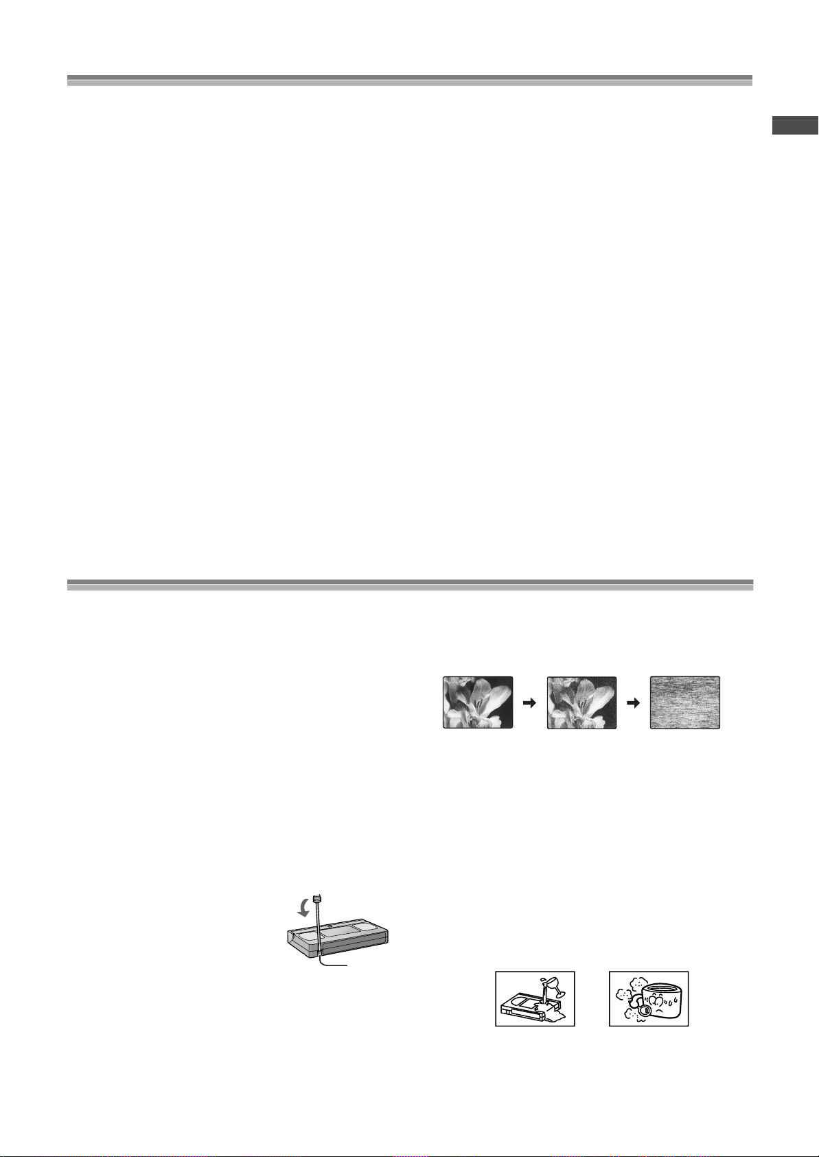
Dirt on the video heads
If the video heads get dirty, pictures will not be recorded or played
back clearly. (See the following conditions.)
If this happens, insert and eject a cassette 5
successively to remove the dirt from the video heads.
If a clear picture is not produced, insert a commercially available
cleaning cassette. Then, press [REC¥] (¥REC/OTR)
(l page 7, 9) and keep it running for approximate 10 seconds to
clean the video heads.
If the problem still persists after performing all of the measures
listed above, contact a service personnel to request assistance.
Heads mainly become dirty because of scratched or dirty tapes,
use of the unit in places where temperature and humidity are high,
dust in the air and the other reasons.
Never use tapes on which juice has been spilt or those that are
extremely damaged since this will not only cause the heads to
become dirty, but will also make the unit malfunction.
10 times
–
5
Page 6
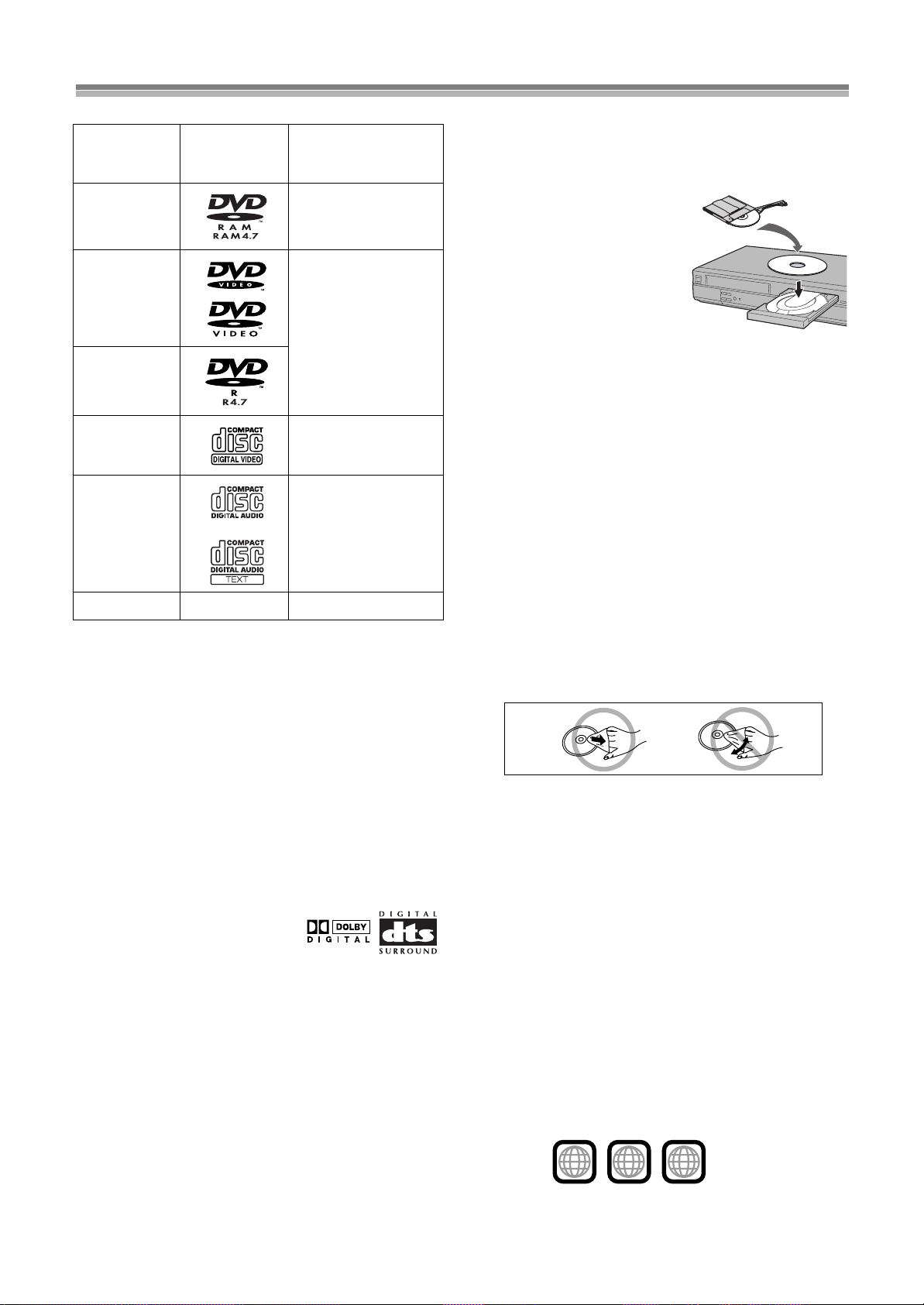
Disc information
, etc.
ªDiscs that can be played
Indication in these
Disc type Logo
DVD-RAM
DVD-Video
DVD-R
Video CD [VCD]
CD
CD-R/RW — [MP3] [WMA]
¢
Discs you can use
These indications show you the features you can use with the
different types of discs.
≥Use discs with the above logos and that conform to
specifications. The unit cannot play other discs correctly.
≥Do not use irregularly shaped discs (e.g. heart-shaped), as these
can damage the unit.
≥It may not be possible to play CD-R, CD-RW, DVD-R and DVD-
RAM in all cases due to the type of disc or condition of the
recording.
operating
instructions
[RAM[
Shown as “DVD-VR” on
the display
[DVD-V[
[CD] [CDtext]
¢
ªDiscs that cannot be played
PAL discs, DVD-ROM, DVD-Audio, CD-ROM, CDV, CD-G, iRW,
DVD-RW, CVD, SVCD, SACD, Divx Video Discs and Photo CD,
DVD-RAM that cannot be removed from their cartridge, and 2.6GB and 5.2-GB DVD-RAM, etc.
ªDVDs that can be played
You can play discs with these symbols.
ªDisc structure
Disc structure and the labels given to the items on discs depend on
the disc type.
Track: the smallest division on CDs and Video CDs, or a single
Chapter: the smallest division on DVD-Video.
Group: collections of tracks and equivalent to folders on data
Title: the largest division on DVD-Video, usually an entire
Program: the division on DVD-RAM equivalent to a single
Play list: the group of scenes on DVD-RAM.
Scene: DVD-RAM program sections specified and grouped into
MP3/WMA file.
discs.
movie.
recording.
play lists on a DVD video recorder.
ªDVD-RAM discs
The DVD-RAM you can play on this unit are those recorded with
DVD video recorders, DVD video cameras, personal computers,
etc. using Version 1.1 of the Video Recording Format (a unified
video recording standard).
≥Remove discs from their
cartridges before use and return
them when you are finished,
making sure that the labels of the
disc and cartridge face the same
way.
≥Some parts of the disc, for
example where one program
ends and another begins, may
not play smoothly.
ªDVD-R discs
Panasonic DVD-R discs recorded and finalized (a process that
allows play on compatible equipment) on a Panasonic DVD video
recorder or DVD video camera are played as DVD-Video on this
unit.
ªCD-R and CD-RW discs
This unit can play CD-R/RW (audio recording disc) recorded with if
CD-DA, video CD, MP3, or WMA. Close the session or finalize
process that allows play on compatible equipment)
after recording.
(a
ªPlaying DVDs and Video CDs
The producer of these discs can control how they are played so
you may not always be able to control play as described in these
operating instructions (for example if the play time is not displayed
or if a Video CD has menus). Read the disc’s instructions carefully.
ªTo clean discs
DVD-Video, Video CD, CD
Wipe with a damp cloth and then wipe dry.
DVD-RAM, DVD-R
≥Clean with an optional DVD-RAM/PD disc cleaner (LF-
K200DCA1, where available).
≥Never use cloths or cleaners for CDs etc.
ªHandling precautions
≥Do not write on the label side with a ball-point pen or other writing
instrument.
≥Do not use record cleaning sprays, benzine, thinner, static
electricity prevention liquids or any other solvent.
≥Do not attach labels or stickers to discs. (Do not use discs with
exposed adhesive from tape or left over peeled-off stickers.)
≥Do not use scratch-proof protectors or covers.
≥Do not use discs printed with label printers available on the
market.
ªRegion number supported by this player
Region numbers are allocated to DVD players and software
according to where they are sold.
The region number of this player is “1”.
The player will play DVD-Video marked with labels containing “1”
or “ALL”.
Examples:
1
ALL
1
2
4
6
Page 7
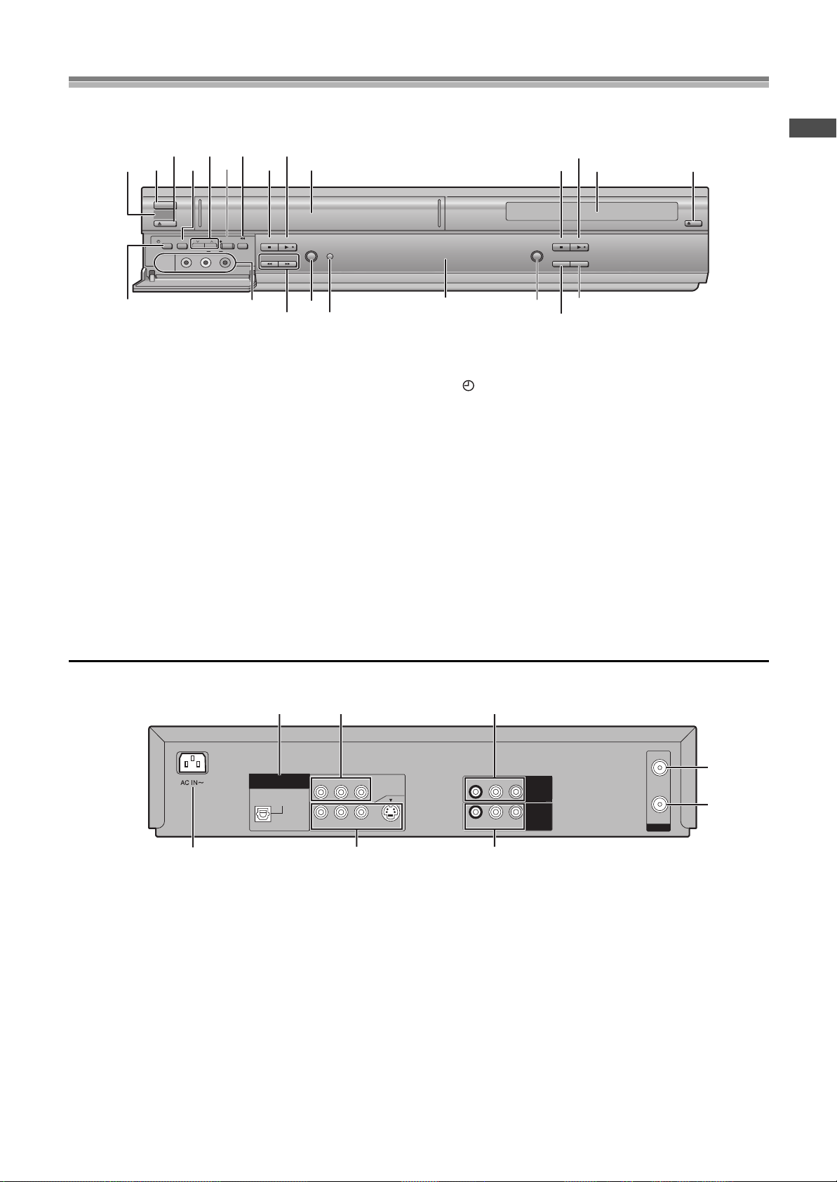
Control reference guide
(2) (4) (6) (8) (1)
(3) (4)
(9) (10)
(11)
(12)
(13)
[C]
(5)
(14)
[D]
[A] [B]
(7)(5)(3)(1)
(2)
ª Common section
[A] Infra-red remote control receiver window
[B] POWERÍ/I button
Press [POWERÍ/I] to switch this unit from on to standby mode
or vice versa. In standby mode, the unit is still connected to the
main AC power.
[C] Display
[D] MUSIC WITH PICTURE button .............. (
l
page 53)
ª VCR section
(1) Tape eject button (<VCR EJECT)........ (lpage 17)
(2) TAPE REFRESH button ......................... (
l
page 27)
(3) Channel up/down buttons
(CHIJ)............................................. (lpage 19,20)
(4) Recording/One-Touch Recording button
(¥REC/OTR)....................................... (lpage 20,21)
(5) Jet Rewind button (6JET REW)........(
l
page 17)
(6) Stop∫ button.......................................... (
l
page 17)
(7) Play1 button.......................................... (
l
page 17)
(8) Cassette compartment
(9) Timer recording button
( TIMER REC).......................................(
l
page 22)
(10) AV2 IN (AUDIO/VIDEO) sockets ............(
l
page 52)
(11) Fast-forward/rewind buttons
(6/REW, FF/5 6, 5)...................(
l
page 17)
(12) PICTURE MODE button..........................(
l
page 19)
(13) Timer program check button
(TIMER CHECK) ......................................(
l
page 23)
(14) Record check button (REC CHECK).....(
l
page 21)
ª DVD section
(1) Stop∫ button ..........................................(lpage 33)
(2) Play1 button ..........................................(
l
page 32)
(3) Disc tray
(4) Disc tray open/close button
(<DVD OPEN/CLOSE) ...........................(
l
page 32)
(5) PROGRESSIVE OUT button...................(
l
page 33)
R-AUDIO-L
VIDEO
OPTICAL
RF
DIGITAL
AUDIO OUT
(PCM/BITSTREAM)
R-AUDIO-L
VIDEO
S-VIDEO
IN
OUT
COMPONENT
VIDEO OUT
(480P/480I)
Y
P
B
P
R
OUT2
(DVD ONLY)
R-AUDIO-L
VIDEO
IN
(AV1)
OUT1
(VCR/DVD)
(2)
(3)
[A]
(1)
[B]
(2)
(3)
(1)
ªCommon section
[A] AC Input socket
[B] OUT1 (VCR/DVD) terminal
ªVCR section
(1) AUDIO IN/VIDEO IN (AV1) sockets....... (lpage 52)
(2) RF IN socket
(3) RF OUT socket
ªDVD section
(1) OUT2 (DVD ONLY) terminal/DIGITAL AUDIO OUT
(OPTICAL, PCM/BIT STREAM).............. (
l
page 47)
(2) OUT2 (DVD ONLY) terminal/
COMPONENT VIDEO OUT (
480P/480I
)
.... (lpage 13)
(3) OUT2 (DVD ONLY) terminal/
AUDIO/VIDEO/S-VIDEO OUT ................. (lpage 13)
This section describes in detail the function of each button, switch and connection socket.
FRONT
POWERÍ/I
VCR
EJECT
TAPE
TIMER REC
CH
REFRESH
VIDEO
AUDIO
AV2 IN
L
REC/OTR
R
JET REW
STOP PLAY
6
/REW
PICTURE
TIMER
MODE
CHECK
5
FF/
PROGRESSIVE OUT
STOP PLAY
REC CHECK
MUSIC
WITH PICTURE
OPEN/CLOSE
DVD
Before Use
REAR
7
Page 8

The unit’s display
(1) (2)
(3)
(1)
[A]
(4)
(5) (6) (7)
(3)
(4)
[C]
(2)
[B]
ªCommon section
[A] VCR indicator.....................................(lpage 17,20)
≥When video on this unit is viewed: (Only when the audio/video
cable is not connected lpage 12)
[B] Main display
≥Current time
≥VCR recording and play counter
≥Timer recording Start time
≥Miscellaneous messages, etc.
[C] Main display (orange)
≥Disc play counter
≥Timer recording end time
≥Miscellaneous messages, etc.
ªVCR section
(1) “ ” indication......................................(lpage 17)
≥Lights up when a cassette is inserted.
≥Flashes when recording or timer recording is attempted with no
cassette inserted.
≥“444” indicates that the output selected is “VCR”. It flashes
for approx. 5 seconds immediately after the output is switched.
(2) Tape remaining display indicator .........(lpage 20)
≥Lights up when the remaining time on a cassette is displayed.
(3) Tape speed indicator..............................(lpage 20)
≥SP: When recording or playing in the Normal mode
≥LP: When playing in the Long play mode.
≥EP: When recording or playing in the Extra long play mode.
≥VP: When recording or playing in the five-time (Long play)
mode.
(4) Tape operation status .......................(lpage 17,20)
≥The operation status of this unit, such as playback, fast forward
(or fast rewind)
(5) Recording indicator (REC) (red)........... (lpage 20)
On: while recording or while a timer recording is being
performed
(6) Channel display ..................................... (lpage 20)
≥1, 2, 3, ....., 125 / A1, A2
≥Indicates the channel while in the TV reception mode or the
channel set for timer recording.
(7) Timer program display (red) ................. (lpage 22)
On:
when a timer recording is in standby mode, or being
performed
ªDVD section
(1) “ ” indication..................................... (lpage 17)
≥Lights up when a disc is inserted.
≥“444” indicates that the output selected is “DVD”. It flashes
for approx. 5 seconds immediately after the output is switched.
(2) Disc operation status ............................ (lpage 32)
≥The operation status of this unit, such as playback, pause (still)
(3) Disc type
DVD-VR: DVD-RAM
DVD-V: DVD-Video, DVD-R
V CD: Video CD
CD: Audio CD, CD text
≥When an MP3 or WMA disc is used, “MP3”, “WMA” is indicated
in the Main display section [C].
(4) The display mode of the main display section
PGM: during program play (lpage 36)
TTL: title number (DVD)
GRP: group number (MP3/WMA)
RND: during random play (lpage 36)
CHP: chapter number (DVD)
TRK: track number (Video CD/Audio CD/MP3/WMA)
PG: program number (DVD-RAM)
PL: play list number (DVD-RAM)
REC
REMAIN
SP
LP
EP
VP
VCR
Control reference guide (continued)
PGM
RND
8
Page 9
Control reference guide (continued)
VCR/DVD/TV
VCR/
DVD
VCR/DVD
REC CHECK
REC
CH
VOLUME
TV
TV
VCR DV D
123
789
0
100
4
5
6
SLOW/SEARCH
NAVI
TOP MENU
MENU
RETURN
PROG/CHECK
QUICK REPLAY
DISPLAY
JET REW
TIMER
ENTER
PLAY
LIST
INDEX/SKIP
Í Í
OUTPUT
TRACKING/V-LOCK
AV
;/ D
DIRECT
NAVIGATOR
(1)
(3)
(2)
(4)
(5)
(6)
(7)
(8)
(9)
(10)
(11)
(12)
(13)
(14)
(15)
(16)
(17)
(18)
(19)
(20)
(21)
CANCEL/RESET
MUSIC w/ PICTURE
SEARCH PICTURE SPEED
AUDIO
POSITION MEMORY
VCR/TV
SET UPA-B REPEATREPEAT
PLAY MODE
A.SRD CINEMA
SUBTITLE
ANGLE
(22)
(23)
(24)
(25)
(26)
(27)
(28)
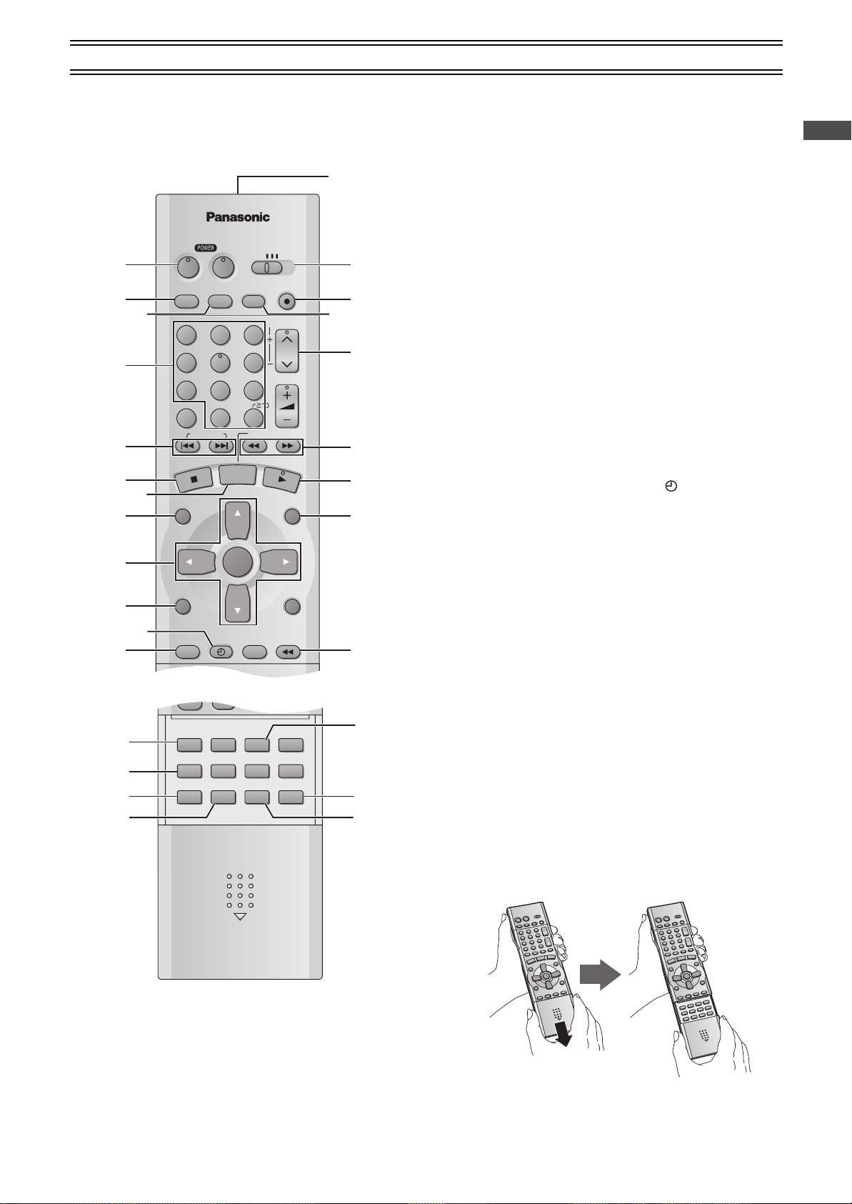
Infra-red Remote Controller
The remote control unit for this unit is a universal remote controller.
As such, some of its buttons are not used to operate this unit.
ªVCR OPERATION
When you operate the video cassette recorder, always select
“VCR” with the [VCR/TV/DVD] switch.
If “VCR” is not selected, normal operation will not be possible.
(1) VCR POWER button (VCRÍ)............(lpage 15,17)
Press [VCRÍ] to switch this unit from on to standby mode or
vice versa. In standby mode, the unit is still connected to the
main AC power.
(2) VCR/DVD output switch button
(VCR/DVD OUTPUT) ...............................(
(3) Record check button
(4) Numeric buttons (0
≥When selecting program positions of the unit
Example: “5”; [0]l[5]
“15”; [1]l[5]
“125”; [100]l[2]l[5]
(REC CHECK) .....(lpage 21)
–
9, 100)....................(lpage 20)
(5) Index search buttons
(:, 9, INDEX)..................................(
(6) Stop button (∫) .......................................(
(7) Pause/slow button (;/D) .......................(
(8) Jet Navigator button (NAVI)...................(
(9) Cursor buttons (3, 4, 2, 1)/
ENTER button .........................................(
(10) Display button (DISPLAY)......................(
(11) Timer recording button (TIMER ) .......(
(12) Timer programming and check button
(PROG/CHECK).......................................(
(13) Infra-red Transmitter
(14) VCR/TV/DVD switch (VCR/TV/DVD)
(15) Recording button (REC¥)......................(
(16) This button does not work.
(17) Tracking/V-Lock and Channel up/down buttons
)..........(lpage 19,20)
(TRACKING/V-LOCK, CH
IJ
(18) Fast-forward/rewind buttons
(6, 5) ................................................(lpage 17)
(19) Play button (1) .......................................(
(20) MENU button...........................................(
(21) Jet Rewind button (JET REW6).........(
(22) CANCEL/RESET button.....................(
(23) MUSIC WITH PICTURE button
(MUSIC w/ PICTURE) ..............................(lpage 53)
(24) SEARCH button ......................................(
(25) Picture mode button (PICTURE)............(
(26) AUDIO button ..........................................(
(27) VCR/TV button ........................................(
≥When the audio/video cable is not connected (l page 12),
press this button to switch the signal of TV or this unit.
(28) Tape speed button (SPEED) ..................(lpage 20)
How to open the remote control
page 17)
l
page 26)
l
page 17)
l
page 17)
l
page 24)
l
page 28)
l
page 31)
l
page 22)
l
page 23)
l
page 20)
l
page 17)
l
page 28)
l
page 17)
l
page 23,31)
l
page 27)
l
page 19)
l
page 31)
l
page 15)
l
Before Use
Hold both sides of the remote control’s cover to open it. (You can
also open it by pressing on the center of it and sliding it down.)
9
Page 10
VCR/DVD/TV
VCR/
DVD
VCR/DVD
REC CHECK
REC
CH
VOLUME
TV
TV
VCR DV D
123
789
0
100
4
5
6
SLOW/SEARCH
NAVI
TOP MENU
MENU
RETURN
PROG/CHECK
QUICK REPLAY
DISPLAY
JET REW
TIMER
ENTER
PLAY
LIST
INDEX/SKIP
Í Í
OUTPUT
TRACKING/V-LOCK
AV
;/ D
DIRECT
NAVIGATOR
(1)
(2)
(3)
(4)
(5)
(6)
(7)
(8)
(9)
(10)
(11)
(12)
(13)
(14)
(15)
CANCEL/RESET
MUSIC w/ PICTURE
SEARCH PICTURE SPEED
AUDIO
POSITION MEMORY
VCR/TV
SET UPA-B REPEATREPEAT
PLAY MODE
A.SRD CINEMA
SUBTITLE
ANGLE
(16)
(17)
(19)
(20)
(21)
(22)
(23)
(24)
(25)
(26)
(18)
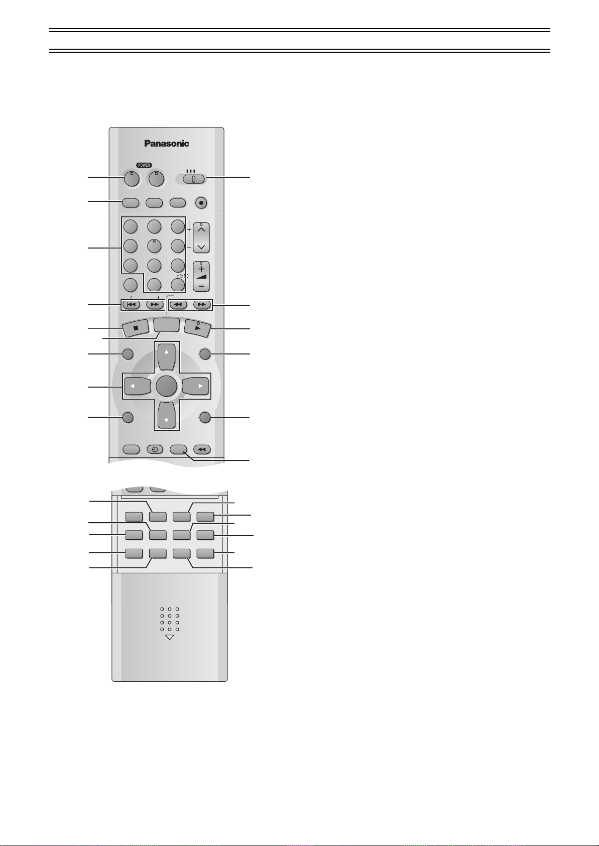
Control reference guide (continued)
ªDVD OPERATION
When you operate the DVD, always select “DVD” with the
[VCR/TV/DVD] switch.
If “DVD” is not selected, normal operation will not be possible.
(1) DVD POWER button (DVDÍ).................(lpage 32)
Press [DVDÍ] to switch this unit from on to standby mode or
vice versa. In standby mode, the unit is still connected to the
main AC power.
(2) VCR/DVD output switch button
(VCR/DVD OUTPUT) ...............................(
(3) Numeric buttons (0
≥When selecting a title, chapter, track, group or play list, etc.
Example: “05”; [5]
“15”; [S10]l[1]l[5]
[MP3] [WMA] “16”; [1]l[6]
“125”; [1]l[2]l[5]
9, S10)..............(lpage 32,34)
–
(4) Skip buttons
(:, 9, SKIP) ....................................(
(5) Stop button (∫) .......................................(
(6) Still button (;/D) ....................................(
(7) Top menu and Direct Navigator button
(TOP MENU, DIRECT NAVIGATOR) .(
(8) Cursor buttons (3, 4, 2, 1)/
ENTER button ....................................(lpage 43,48)
On-screen menu icon button (DISPLAY)
(9)
(10) VCR/TV/DVD switch (VCR/TV/DVD)
(11) Slow/search buttons
(6, 5, SLOW/SEARCH) ...................(
(12) Play button (1) .......................................(
(13) PLAY LIST button ...................................(
page 37,38,40,43,48)
(14) RETURN button...................(
l
(15) QUICK REPLAY button ..........................(
(16) SUBTITLE button....................................(
(17) Advanced surround button (A.SRD).....(
(18) MUSIC WITH PICTURE button
(MUSIC w/ PICTURE) ..............................(lpage 53)
(19) PLAY MODE button ................................(
(20) REPEAT button .......................................(
(21) AUDIO button ..........................................(
(22) ANGLE button .........................................(
(23) CINEMA button .......................................(
(24) POSITION MEMORY button ...................(
(25) DVD SET UP menu button (SET UP).....(
(26) A-B REPEAT button................................(
page 17)
l
page 34)
l
page 33)
l
page 35)
l
page 37,38)
l
.(lpage 43)
page 35)
l
page 32)
l
page 37)
l
page 35)
l
page 40)
l
page 41)
l
page 36)
l
page 35)
l
page 40)
l
page 40)
l
page 41)
l
page 33)
l
page 48)
l
page 35)
l
10
Page 11
Control reference guide (continued)
VCR/DVD/TV
VCR/
DVD
VCR/DVD
REC CHECK
REC
CH
VOLUME
TV
TV
VCR DV D
123
789
0
100
4
5
6
SLOW/SEARCH
NAVI
TOP MENU
MENU
RETURN
PROG/CHECK
QUICK REPLAY
DISPLAY
JET REW
TIMER
ENTER
PLAY
LIST
INDEX/SKIP
Í Í
OUTPUT
TRACKING/V-LOCK
AV
;/ D
DIRECT
NAVIGATOR
(1)
(2)
(3)
(4)
(5)
(6)
30
30
20
20
Infra-red remote control receiver window
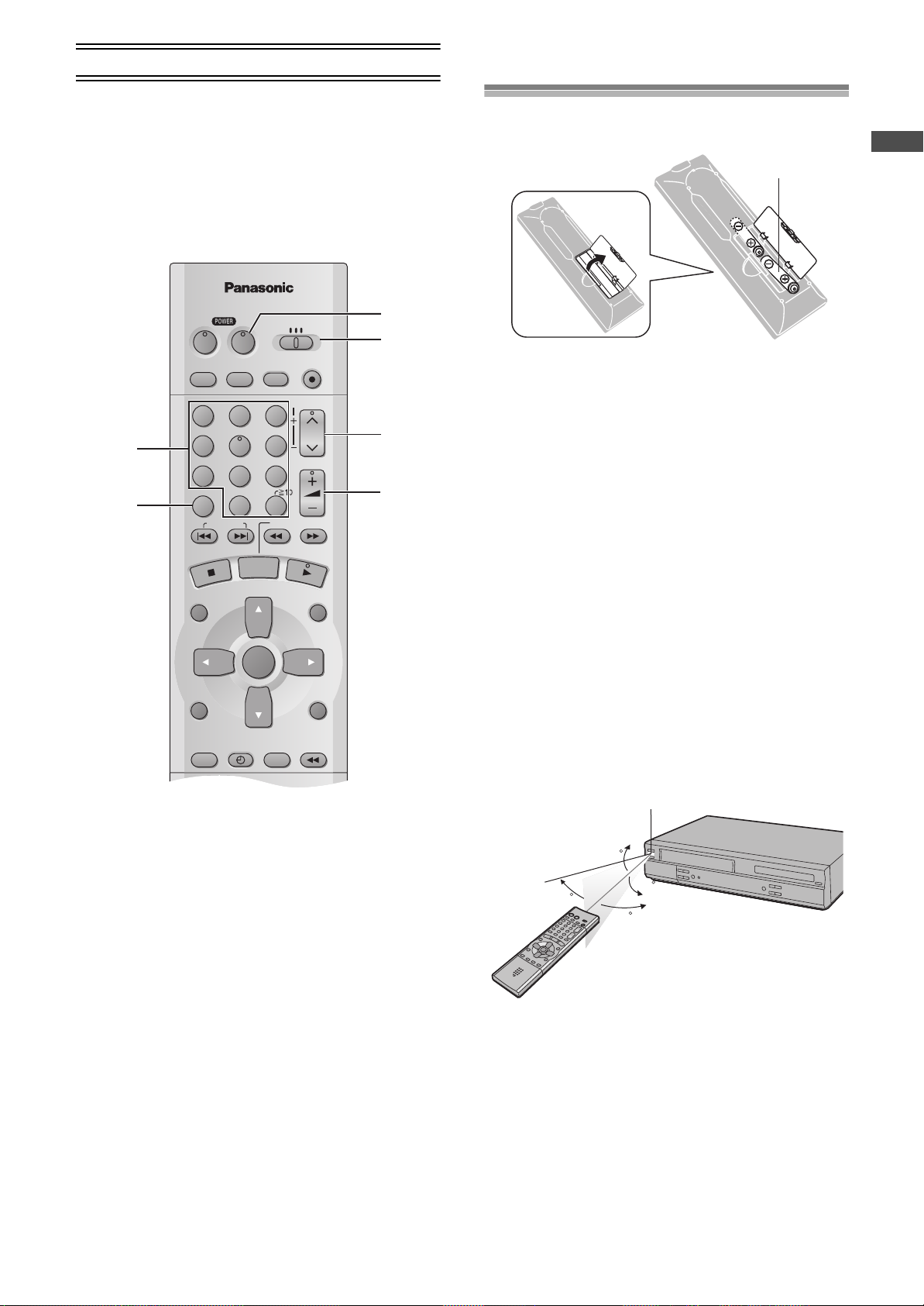
The remote control
ªTV OPERATION
Only Panasonic TVs can be operated with the provided remote
control. The settings for operating the TV with the remote control
have already been made.
No additional settings need to be performed.
However, some Panasonic TVs cannot be operated using this
remote control.
Installing the Batteries
Insert the batteries with the polarity (+ and -) correctly aligned.
R6, AA, UM-3
Before Use
Power Source for the Remote Controller:
The remote controller is powered by 2 “AA”, “UM-3” or “R6” size
batteries. The life of the batteries is about one year, although this
depends on the frequency of use.
Precautions for Battery Replacement:
≥Load the new batteries with their polarity (+ and -) aligned
correctly.
≥Do not apply heat to the batteries, or an internal short circuit may
occur.
≥If you do not intend to use the remote controller for a long period
of time, remove the batteries and store them in a cool and dry
place.
≥Remove spent batteries immediately and dispose of them
properly.
≥Do not use an old and a new battery together, and never use an
alkaline battery with a manganese battery.
≥Do not use rechargeable batteries.
When you operate the TV, always select “TV” with the
[VCR/TV/DVD] switch.
If “TV” is not selected, normal operation will not be possible.
(1) Numeric buttons (0–9, 100)...............(lpage 15,20)
(2) Television input mode selector (AV)
(3) TV POWER button (TVÍ)
≥Selects the television channel.
≥Selects TV input or AV input.
Press to switch the TV from on to standby mode or vice
versa. In standby mode, the TV is still connected to the
mains.
≥With some TV models, it may only be possible to switch the
TV to the standby mode using this button.
In this case, use [AV], [CH]IJ or the numeric buttons to
switch the TV on.
(4) VCR/TV/DVD switch (VCR/TV/DVD)
(5) Channel up/down buttons (CH
(6) TV volume up/down buttons (rN s, VOLUME)
≥Selects the required television channel.
≥Adjusts the volume of the TV.
IJ
)
Use
Aim at the receiver window, avoiding obstacles, at a maximum
range of 7 m (23 feet) directly in front of the unit.
≥Keep the transmission window and the unit’s sensor free from
dust.
≥Operation can be affected by strong light sources, such as direct
sunlight, and the glass doors on cabinets.
11
Page 12
Connections
TV Set (Not supplied)
Antenna (Not supplied)
Antenna Input
Connector
To Power Outlet
R-AUDIO-L
VIDEO
OPTICAL
RF
DIGITAL
AUDIO OUT
(PCM/BITSTREAM)
R-AUDIO-L
VIDEO
S-VIDEO
IN
OUT
COMPONENT
VIDEO OUT
(480P/480I)
Y
P
B
P
R
OUT2
(DVD ONLY)
R-AUDIO-L
VIDEO
IN
(AV1)
OUT1
(VCR/DVD)
TV Set (Not supplied)
Antenna (Not supplied)
Antenna Input
Connector
To Power Outlet
VIDEO INAUDIO IN
Audio/video cable
(Not supplied)
OPTICAL
DIGITAL
AUDIO OUT
(PCM/BITSTREAM)
R-AUDIO-L
VIDEO
S-VIDEO
COMPONENT
VIDEO OUT
(480P/480I)
Y
P
B
P
R
OUT2
(DVD ONLY)
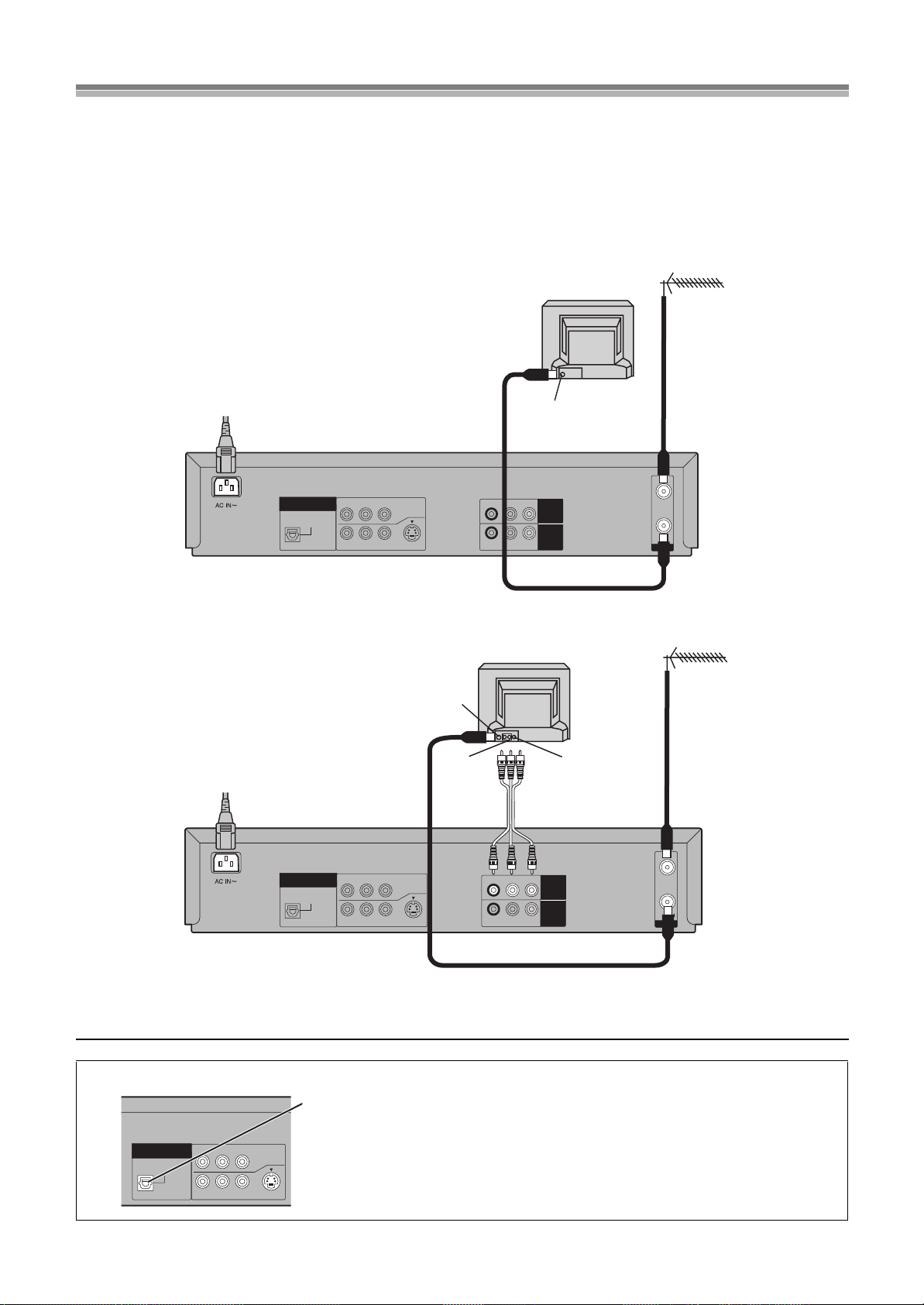
This section shows you how to connect the unit to an antenna, TV, etc.
When the unit is turned on after connecting the antenna cable and the AC power cord, Plug in Auto Tuning and Auto Clock Setting
start automatically.
Basic Connections
The following connections are required to record the video cassette and play back the video cassette and discs through the TV.
Preparation
≥Refer to the television’s operating instructions.
≥Turn the television off and disconnect its AC power supply cord.
OUT2
(DVD ONLY)
DIGITAL
AUDIO OUT
(PCM/BITSTREAM)
OPTICAL
Y
R-AUDIO-L
COMPONENT
P
B
P
VIDEO
R
VIDEO OUT
(480P/480I)
S-VIDEO
R-AUDIO-L
R-AUDIO-L
VIDEO
VIDEO
OUT1
(VCR/DVD)
IN
(AV1)
IN
OUT
RF
Connection to a TV using the Audio/Video Input Sockets
Note:
≥Connect audio/video cables directly to your TV. The video signals on DVDs and videotapes have copyright protection. The video may not be
shown correctly if you connect through an A/V selector or other equipment.
To enjoy sound through other audio equipment
You can output digital signals from this unit’s OPTICAL DIGITAL AUDIO OUT terminal,
enabling you to enjoy the powerful surround effects found on discs recorded with Dolby Digital
or DTS. Connect an amplifier with built-in decoders. See page 47 for connection examples.
12
Page 13
Connections (continued)
OPTICAL
DIGITAL
AUDIO OUT
(PCM/BITSTREAM)
R-AUDIO-L
VIDEO
S-VIDEO
COMPONENT
VIDEO OUT
(480P/480I)
Y
P
BPR
OUT2
(DVD ONLY)
COMPONENT
VIDEO IN
Y
P
B
P
R
AUDIO IN
L
R
(Not supplied) (Not supplied)
OPTICAL
DIGITAL
AUDIO OUT
(PCM/BITSTREAM)
R-AUDIO-L
VIDEO
S-VIDEO
COMPONENT
VIDEO OUT
(480P/480I)
Y
P
BPR
OUT2
(DVD ONLY)
AUDIO IN
L
R
IN
S VIDEO
(Not supplied)(Not supplied)
DVD-only terminal
OPTICAL DIGITAL
AUDIO OUT terminal OUT2 terminal
Output common to
VCR and DVD
OUT1 (VCR/DVD)
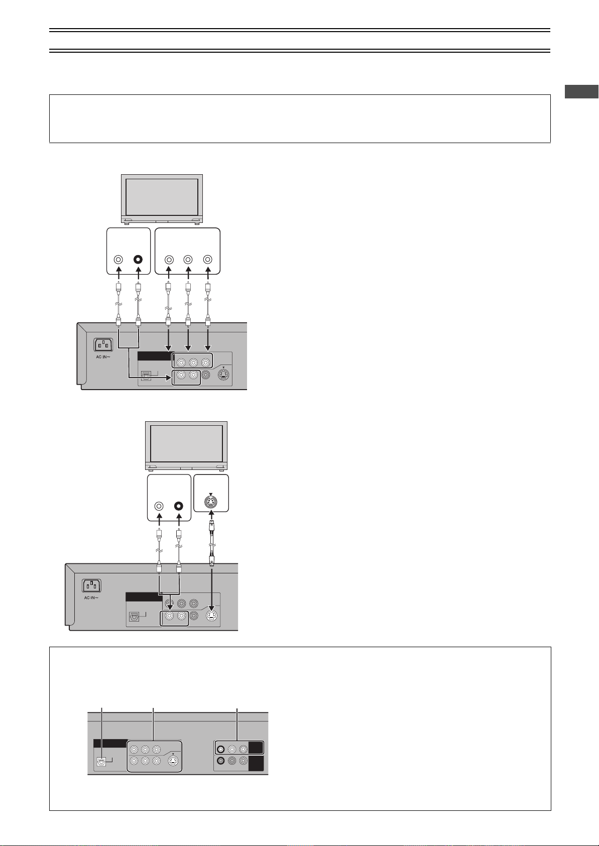
To enjoy DVD video with a higher image quality
The following connections are for the DVD section only.
Carry out the Basic Connections described on the left page to view video from the VCR section.
≥You may need to change the video-input mode on the TV to view video from the VCR and DVD sections. Read your television’s
operating instructions for details.
Connection to a TV using the COMPONENT VIDEO OUT terminal (progressive out)
ª COMPONENT VIDEO OUT terminal (progressive out)
These terminals can be used for either interlace or progressive output and
provide a purer picture than the S-VIDEO OUT terminal.
Connection using these terminals outputs the color difference signals (P
) and luminance signal (Y) separately in order to achieve high fidelity in
P
R
reproducing colors.
≥The description of the component video input terminals depends on the
television or monitor (e.g. Y/P
terminals of the same color.
≥When making this connection, ensure you connect the audio cables (not
supplied) to the corresponding audio input terminals on the television.
≥After making this connection, change the black level for a better picture
(Black Level Control lpage 49).
To enjoy progressive video
1) Connect to the component video input terminals on a 480P compatible
television. (Video will not be displayed correctly if connected to an
incompatible television.)
2) In SET UP menus, set “Progressive Out (Component)” to “Enable”
(lpage 49).
Change “Video output mode” to “480P” in the on-screen menu (lpage 46
3)
≥
All televisions manufactured by Panasonic and that have 480P input connectors
are compatible. Consult the manufacturer if you have another brand of television.
Connection to a TV using the S-VIDEO OUT terminal
ª S-VIDEO OUT terminal
The S-VIDEO OUT terminal achieves a more vivid picture than the VIDEO
OUT terminal by separating the chrominance (C) and luminance (Y) signals.
(Actual results depend on the television.)
≥When making this connection, ensure you connect the audio cables to the
corresponding audio input terminals on the television.
≥Connect to a different terminal group (e.g., “VIDEO 2”) than that you used
for the connection through this unit’s OUT1 (VCR/DVD) terminal.
Picture from this unit’s VCR will not appear when you use the same group
input terminal connections because the S-video terminal input takes
precedence.
, Y/B-Y/R-Y, Y/CB/CR). Connect to
B/PR
Before Use
/
B
).
About the output terminal common to VCR and DVD and the one exclusively for DVD
This unit has an output terminal common to VCR and DVD and one exclusively for DVD.
OPTICAL
OUT2
(DVD ONLY)
DIGITAL
AUDIO OUT
(PCM/BITSTREAM)
COMPONENT
P
B
P
R
Y
R-AUDIO-L
VIDEO OUT
(480P/480I)
VIDEO
S-VIDEO
≥For the OUT1 (VCR/DVD) terminal, VCR and DVD outputs can
be switched or it can be assigned for VCR output only.
≥The OUT2 terminal can only output the DVD signal.
R-AUDIO-L
R-AUDIO-L
VIDEO
VIDEO
OUT1
(VCR/DVD)
IN
(AV1)
Note:
≥Even if “AUTO” is selected in “OUT1 [VCR/DVD]” of the VCR
MENU
“
OPTION” (lpage 30), the desired output may not be
selected depending on the operation.
In this case, press [VCR/DVD OUTPUT] on the remote controller
to switch manually.
≥When Video is switched to DVD or vice versa, the audio volume
may suddenly increase or decrease.
This is because when the audio output of this unit is connected
to the TV, etc., the audio output of the DVD is generally lower.
When you increase the volume level to play back DVD audio,
reduce it when playback is finished.
13
Page 14
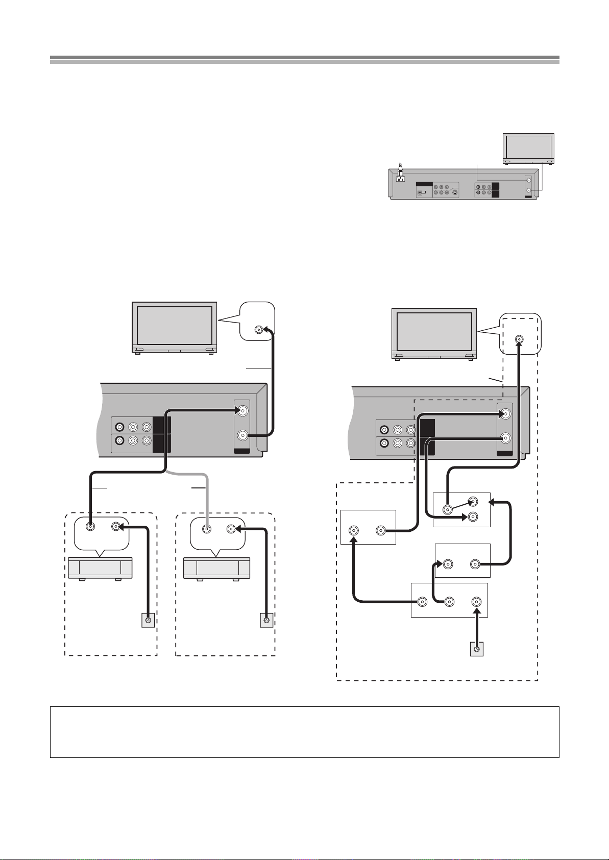
Cable Connection
75 ohm Coaxial Cable
ªOne cable TV box/satellite receiver
The following cable hook-up allows this unit -TV functions except
for viewing one channel while recording another.
ªTwo cable TV boxes
The following cable hook-up allows the unit’s functions, including
viewing one channel while recording another, but it requires two
cable TV Converter/Descrambler Boxes, one Switch Box and one
2-Way Splitter.
R-AUDIO-L
VIDEO
RF
IN
OUT
R-AUDIO-L
VIDEO
IN
(AV1)
OUT1
(VCR/DVD)
VHF/UHF
RF IN
RF INRF OUT
VHF/UHF
OUT IN
75 ohm Coaxial
Cables (Not supplied)
Cable TV
Converter Box
75 ohm Coaxial Cable
(Supplied)
From household
cable TV jack
DSS receiver
or
From household
home satellite system
(Dishnetwork/DSS) jack
R-AUDIO-L
VIDEO
RF
IN
OUT
R-AUDIO-L
VIDEO
IN
(AV1)
OUT1
(VCR/DVD)
VHF/UHF
RF IN
OUT1 OUT2
IN OUT
IN
IN2
IN1
IN OUT
From household
cable TV jack
Cable TV
Converter Box
2-Way
Splitter
Switch Box
¢
Cable TV Converter Box
¢
Not available from our company.
Please contact your cable company.
Connect with 75 ohm
Coaxial Cable
Cable-This Unit-TV (For CATV/PAY Channels Recording/Playback)
The unit has an extended range, and can tune the Low-Band, Mid-Band, Super-Band, Hyper-Band, Ultra-Band, and Special cable channels
(Channels A-5sA-1, AsW, AAsFFF, GGGsWWW, WWWr1sWWWr12, 100s125, 5A). Also, the unit can tune to any of the 56 UHF
channels (14s69). Refer to Channel Set on page 29 .
BASIC Hook-Up
Since the unit can tune Mid and Super Bands, this connection will provide the reception of
all cable channels except those which are intentionally scrambled.
However, if you subscribe to a special channel which is scrambled you will probably have a
descrambler box for proper reception. The unit by itself cannot properly receive a
scrambled program since it does not contain a descrambler. In order for the unit to properly
receive a scrambled program, your existing descrambler must be used. There are two
OPTICAL
OUT2
(DVD ONLY)
DIGITAL
AUDIO OUT
(PCM/BITSTREAM)
COMPONENT
P
BPR
Y
VIDEO OUT
(480P/480I)
VIDEO
S-VIDEO
R-AUDIO-L
commonly used methods of connection in this case.
Typical Cable System Hook Ups with Cable Converter/Descrambler Boxes
R-AUDIO-L
VIDEO
OUT1
(VCR/DVD)
IN
(AV1)
R-AUDIO-L
VIDEO
IN
OUT
RF
Since the unit has an extended range of tuning, tuning-programing of non-scrambled Mid-Band and Super-Band TV programs is possible.
When a cable converter or descrambler box is connected to the unit, all timer-controlled recording functions will continue to operate with
the exception of charging channels automatically. CATV Channel selection will have to be performed with the cable converter. Timercontrolled recording from CATV Channels is therefore limited to one channel at any given time.
14
Page 15
Tuning the TV to your unit
VCR/DVD/TV
VCR/DVD
REC CHECK
REC
CH
VOLUME
TV
TV
VCR DVD
123
789
0
100
4
5
6
SLOW/SEARCH
NAVI
TOP MENU
MENU
RETURN
PROG/CHECK
QUICK REPLAY
DISPLAY
JET REW
TIMER
ENTER
PLAY
LIST
INDEX/SKIP
OUTPUT
TRACKING/V-LOCK
AV
DIRECT
NAVIGATOR
CANCEL/RESET
MUSIC w/ PICTURE
SEARCH PICTURE SPEED
AUDIO
POSITION MEMORY
VCR/TV
SET UPA-B REPEATREPEAT
PLAY MODE
A.SRD CINEMA
SUBTITLE
ANGLE
VCR/TV/DVD
VCR
VCR/TV
MENU
VCR/
DVD
POWER /I
TIMER
CHECK
PICTURE
MODE
EJECT
VCR
PULL-OPEN
STOP PLAY
POWER /I
3
On Screen Display
Channel being
searched
Plug in Auto Tuning
Auto Tuning searches for TV stations from VHF minimum to UHF
maximum and memorizes every tuned program position.
Notes:
≥If the unit is turned on with the antenna not connected, all
channels are skipped.
≥When Auto Tuning is canceled halfway, Auto Tuning is not
executed even if the unit is turned off and then turned on again.
In this case, see page 16 “To Restart Plug in Auto Tuning”.
Preparations
≥Confirm that the antenna cable and the AC power cord is
connected correctly.
≥Turn on the TV.
≥Switch [VCR/TV/DVD] to “VCR”.
Operations
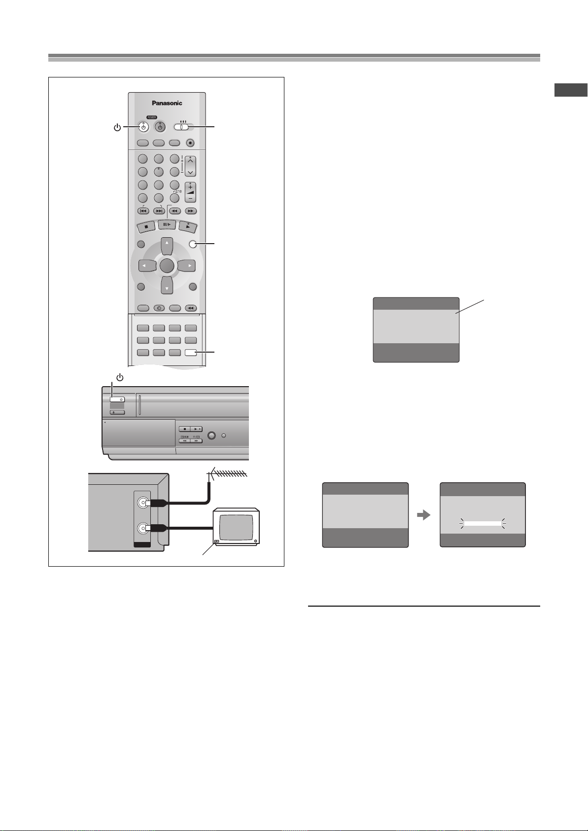
Press [POWERÍ/I] (VCRÍ) to turn on this unit.
1
Plug in Auto Tuning starts and the unit puts the stations it can
receive into channels (Channel plan lpage 29).
Before Use
IN
OUT
RF
The unit supplies a signal to the TV via the RF coaxial cable on
channel 3 or 4.
It is possible to view the video picture on your TV in the same way
that you watch TV broadcasts.
If you have connected the unit to the TV through the video and
audio input sockets, then you do not need to follow the procedure
below.
When the unit is turned on after unpacking and connecting
the antenna cable and the AC power cord, Plug in Auto Tuning
and Auto Clock Setting start automatically.
The unit is fitted with its own tuner (just like a normal TV) and can
be preset to receive up to 181 TV broadcast stations.
AUTO CHANNEL SET
PROCEEDING
END : MENU
Press [VCR/TV] to select the VCR mode.
2
Select a program number on the TV which you wish
3
2
to use as the video viewing channel.
≥Tune your TV until the Auto Tuning screen appears on the
TV screen (Please refer to the TV manufacturers operating
instructions regarding tuning.).
≥During Auto Tuning, the TV program screen does not appear,
and the Auto Tuning screen appears instead.
≥The unit starts Auto Clock Setting when the Auto Tuning is
completed.
AUTO CLOCK SET
AUTO CLOCK SETTING
IN PROGRESS.
PLEASE WAIT.
AUTO CHANNEL SET
PROCEEDING
END :MENU
2
≥When Auto Tuning and Auto Clock Setting are completed,
the on screen display disappears and the lowest channel
position at which a broadcast can be tuned in is received,
and the time is displayed on the unit’s display.
To Cancel Auto Tuning Mid-Operation
Press [MENU] during Auto Tuning. Auto Tuning is cancelled.
Notes:
≥Auto Tuning will stop halfway by turning this unit off, pressing
[MENU], playback or a power failure during Auto Tuning.
≥The unit automatically determines the type of transmission (“TV”
or “CATV”). When there are 5 or more CATV channels, the
antenna system “CATV” is automatically selected; when there
are 4 or fewer CATV channels, the “TV” is selected. If a change is
required, conduct the resetting procedure described in
“ANTENNA SYSTEM” on page 29.
ªTo set the channels manually (lpage 29)
ªIf the unit couldn’t set the clock automatically
The MANUAL CLOCK SET screen appears. Set the time manually
(lpage 28).
15
Page 16
Tuning the TV to your unit (continued)
VCR/DVD/TV
VCR/DVD
REC CHECK
REC
CH
VOLUME
TV
TV
VCR DVD
123
789
0
100
4
5
6
SLOW/SEARCH
NAVI
TOP MENU
MENU
RETURN
PROG/CHECK
QUICK REPLAY
DISPLAY
JET REW
TIMER
ENTER
PLAY
LIST
INDEX/SKIP
OUTPUT
TRACKING/V-LOCK
AV
DIRECT
NAVIGATOR
CANCEL/RESET
MUSIC w/ PICTURE
SEARCH PICTURE SPEED
AUDIO
POSITION MEMORY
VCR/TV
SET UPA-B REPEATREPEAT
PLAY MODE
A.SRD CINEMA
SUBTITLE
ANGLE
CH
VCR
VCR/TV
CH
MENU
VCR/
DVD
TIMER REC
TAPE
REFRESH
AV2 IN
REC/OTR
CH
TIMER
CHECK
PICTURE
MODE
EJECT
VCR
STOP PLAY
JET REW
VIDEO
AUDIO
L
R
POWER /I
Display Symbol
On Screen Display
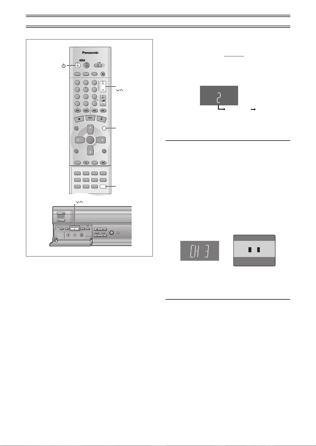
ªTo Restart Plug in Auto Tuning
Make sure there is no video cassette and disc loaded in the unit.
1) Keep both [CH] I and J on this unit
for 3 seconds or more while the unit is powered on.
≥The channel displayed on the unit’s display disappears for a
moment then changes to 2.
Disappears 2
2) Disconnect the AC power cord and then reconnect it.
3) Turn on this unit.
4) Press [VCR/TV] to select the VCR mode.
≥Plug in Auto Tuning restarts.
If Auto Tuning stops halfway by turning the unit off or a power
failure:
1) Disconnect the AC power cord and then reconnect it.
2) Turn on this unit.
≥Plug in Auto Tuning restarts.
pressed simultaneously
Preparations
≥Switch [VCR/TV/DVD] to “VCR”.
ªTo Change the RF Output Channel
In some rare cases after tuning the TV to your unit, interference
may be visible on the picture. To get rid of this interference, you
can manually adjust the RF output channel a few channels up and
down from the current setting. The procedure is described below.
1) Hold down [MENU] for 5 seconds or more.
≥The unit’s display changes as shown below and the VCR
picture on the TV displays this pattern.
Panasonic VCR
END: MENU
2) Enter the desired channel number (3 or 4) by [CH]IJ.
3()4
3) Press [MENU] to finish the setting mode.
4) Retune your TV to the new RF channel for this unit.
Note:
≥Even if the RF output channel has been changed, it is not
necessary to perform Auto Tuning.
16
Page 17
To Switch to the Desired Video
VCR/DVD/TV
VCR/DVD
REC CHECK
REC
CH
VOLUME
TV
TV
VCR DVD
123
789
0
100
4
5
6
SLOW/SEARCH
NAVI
TOP MENU
MENU
RETURN
PROG/CHECK
QUICK REPLAY
DISPLAY
JET REW
TIMER
ENTER
PLAY
LIST
INDEX/SKIP
OUTPUT
TRACKING/V-LOCK
AV
DIRECT
NAVIGATOR
CANCEL/RESET
MUSIC w/ PICTURE
SEARCH PICTURE SPEED
AUDIO
POSITION MEMORY
VCR/TV
SET UPA-B REPEATREPEAT
PLAY MODE
A.SRD CINEMA
SUBTITLE
ANGLE
VCR/TV/DVD
MENU
JET REW
VCR/TV
VCR/DVD
OUTPUT
VCR/
DVD
VCR
3, 4, 2, 1
ENTER
On Screen Display
When video from the video
cassette is selected
When video from the
disc is selected
Display Symbols
(Common Output)
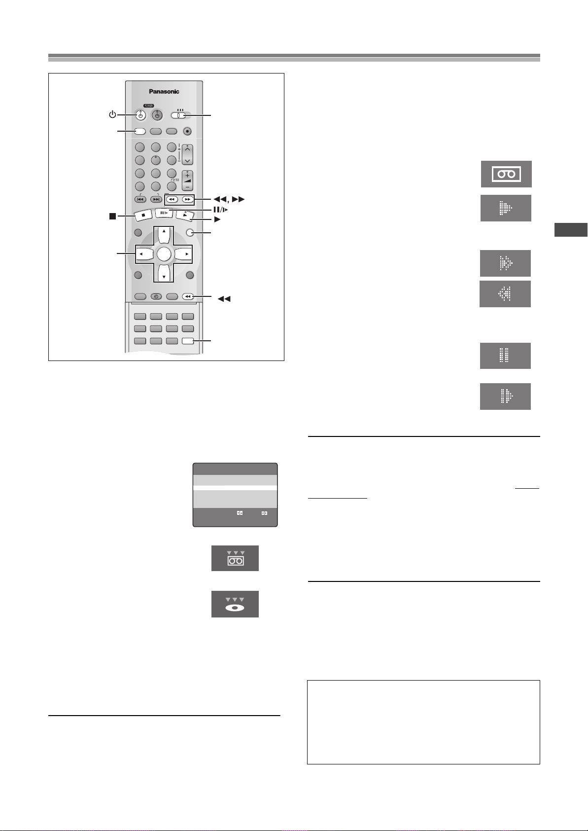
This unit allows both video cassette and DVD discs to be played back.
You can set the unit so that the output is automatically switched to
the device which starts playback.
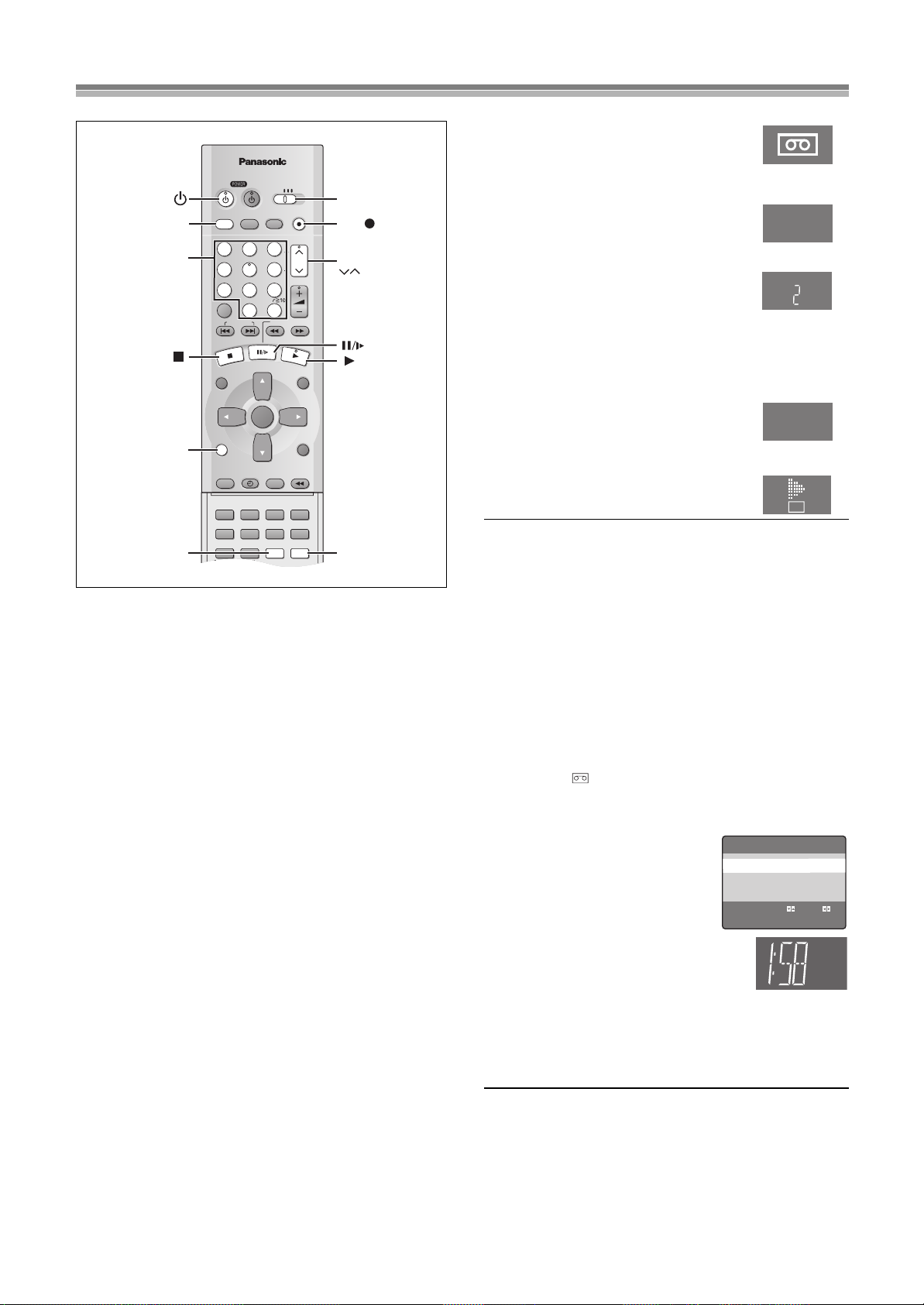
Operations
1
Press [MENU] to show the VCR MENU.
2
Select “OPTION” by
pressing [Cursor]34 and
then press [ENTER].
3
Select “OUT1[VCR/DVD]” by
pressing [Cursor]34.
4
Select “VCR”, “MANUAL” or
“AUTO” by pressing
[Cursor]2 1.
VCR: Only VCR outputs
≥Even if you press
the DVD video is not shown.
MANUAL: When the VCR output and
≥Press [VCR/DVD OUTPUT] to switch
to the desired video source.
≥Each press of [VCR/DVD OUTPUT]
alternately switches between VCR and DVD.
≥They are not switched automatically.
AUTO: Initially set at this position
≥VCR and DVD are automatically switched depending on the
manipulation or the unit operation.
≥You may also switch them by pressing [VCR/DVD OUTPUT].
To make the on screen display disappear
Press [MENU] twice.
Note:
You can switch to the desired video with the above operation only when
≥
the video from this unit is viewed through the OUT1 (VCR/DVD) terminal.
≥Depending on the operation, the desired output may not be
switched automatically even if “AUTO” is selected. In this case,
press [VCR/DVD OUTPUT] to switch it manually.
[VCR/DVD OUTPUT],
DVD output are manually
switched
OPTION 2/2
MTS ≥MAIN SAP MONO
OUT1[VCR/DVD]
VCR MANUAL ≥AUTO
SELECT : s/r:
END :MENU
Display Symbols
VCR Playback
Basic Playback
Preparations
≥Confirm that the TV is on and the unit viewing channel is
selected.
≥Switch [VCR/TV/DVD] to “VCR”.
≥Press [VCR Í] to turn on the unit.
≥Press [VCR/TV] to select the VCR mode.
Operations
1
Insert a recorded video cassette
tape.
2
Start viewing the picture by
pressing [ 1](PLAY).
≥Play starts automatically if you insert a
prerecorded tape or one that has had its
tab (Tapes lpage 5) removed.
3
Search forward (Cue)/backward
(Review) by tapping [ 5] or [6].
≥To change back to normal playback,
press [ 1](PLAY).
≥If you keep [ 5] or [6] pressed,
search playback is activated while the
button is pressed, and operation returns
to normal playback when the button is
released.
4
View a still picture by pressing
≥To continue normal playback, press
[ 1](PLAY) or [;/D].
5
View a slow motion picture.
≥Keep [;/D] pressed for 2 seconds or
more.
≥To continue normal playback, press
[ 1](PLAY).
To stop viewing the picture
∫].
Press [
To Eject the Video Cassette Using the Remote Controller
You can eject the video cassette with [<VCR EJECT] on the unit.
You can also use the remote controller. Keep pressing [
remote controller for at least 3 seconds.
Fast-forwarding or Rewinding the Tape
Press [ 5] or [6] in the stop mode.
≥To stop fast-forwarding or rewinding, press [
To Obtain a Higher Speed Rewind (Jet Rewind)
Press [JET REW6].
The “J : REW” indication appears on the TV screen and the unit’s
display. (except when the remaining tape time indication appears)
≥Depending on a cassette or an operating condition, the rewind
speed may change somewhat.
≥The tape counter is reset to “0:00.00” when the tape is rewound
to the beginning.
≥Depending on a cassette, this function may not work.
≥To stop Jet Rewind, press [
S-VHS Quasi Playback (SQPB)
It is also possible to play back tapes recorded in the S-VHS
system.
≥Some picture noise may occur depending on the type of tape
used.
≥It is not possible to fully obtain the high resolution that S-VHS
is capable of.
It is not possible to record in the S-VHS system with this unit.
17
VCR
[;/D].
∫] on the
∫].
∫].
(continues on the next page)
Page 18
VCR Playback (continued)
VCR/DVD/TV
VCR/DVD
REC CHECK
REC
CH
VOLUME
TV
TV
VCR DVD
123
789
0
100
4
5
6
SLOW/SEARCH
NAVI
TOP MENU
MENU
RETURN
PROG/CHECK
QUICK REPLAY
DISPLAY
JET REW
TIMER
ENTER
PLAY
LIST
INDEX/SKIP
OUTPUT
TRACKING/V-LOCK
AV
DIRECT
NAVIGATOR
CANCEL/RESET
MUSIC w/ PICTURE
SEARCH PICTURE SPEED
AUDIO
POSITION MEMORY
VCR/TV
SET UPA-B REPEATREPEAT
PLAY MODE
A.SRD CINEMA
SUBTITLE
ANGLE
TIMER REC
TAPE
REFRESH
AV2 IN
REC/OTR
CH
TIMER
CHECK
PICTURE
MODE
EJECT
VCR
STOP PLAY
JET REW
VIDEO
AUDIO
L
R
TRACKING/V-LOCK
PICTURE
VCR VCR/TV/DVD
CH
POWER /I
POWER /I
VCR/
DVD
Beginning of Tape
Repeat Playback
End of
Recorded Part
Control signal Interruption
(at least 5 sec.)
PLAY
REW
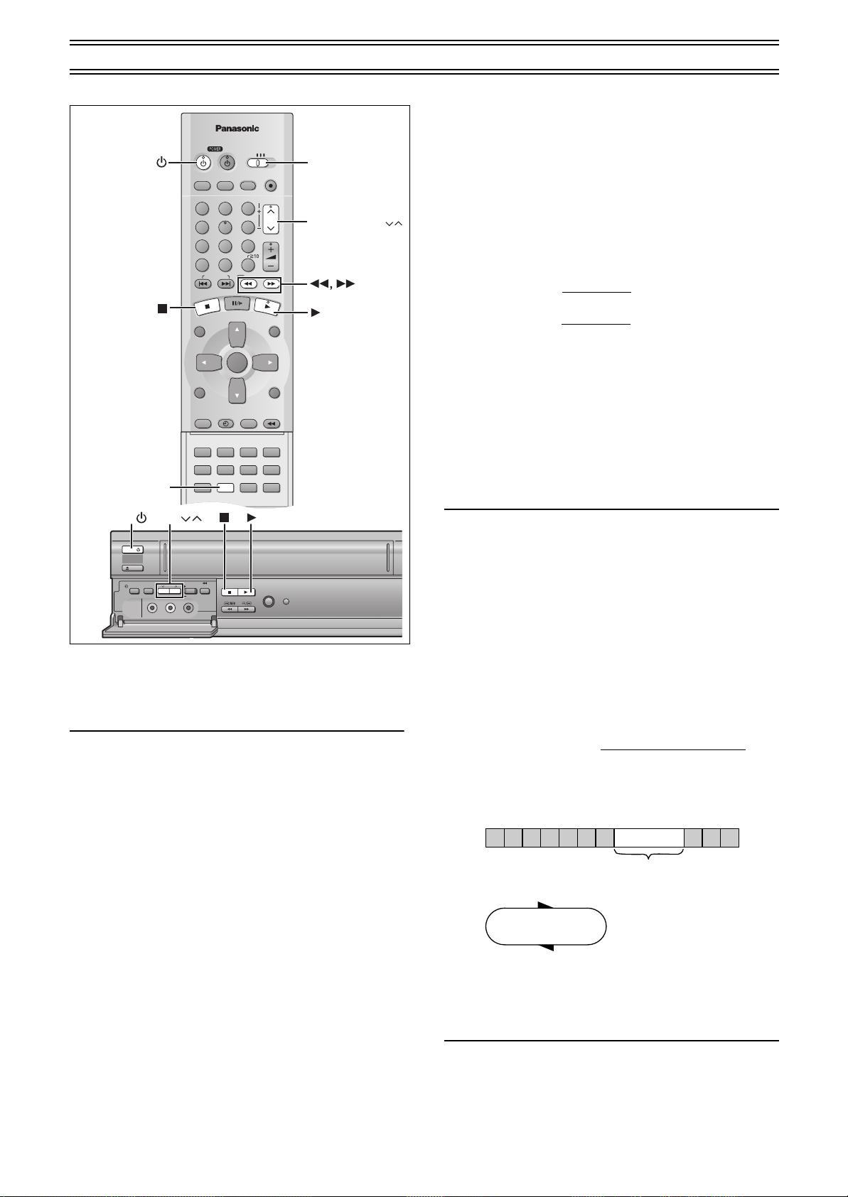
Other Playback Functions
To Stop Playback Automatically
(Playback Off Timer Function)
If you set the playback duration, the playback will stop
automatically.
After the set playback time has elapsed, this unit automatically
stops playback and switches off.
Operations
1 During normal playback
Press [PLAY1] on this unit for more than 2
seconds.
Press [PLAY1] on this unit repeatedly to select the
2
desired playback duration on the unit’s display.
Repeatedly pressing this button changes the indication in the
following order:
Counter display (normal playback mode)
>30 (min.)>60 (min.)>90 (min.)
>120 (min.)>180 (min.)>240 (min.)>
Counter display (normal playback mode)
≥This unit will automatically switch off when Play-Off Timer is
completed.
To Obtain a Higher Speed Picture than
Cue, Review (Jet Search)
During playback, tap
≥Select search speed to view the picture recorded. (lpage 30)
≥The picture that appears in the EP or VP mode at approx. 35
times speed may be distorted.
A vertical scroll may occur. It is not a malfunction but if it
happens, change to approx. 27 times speed.
≥The picture may not be in color or may be distorted depending on
the TV.
≥Press [ 1](PLAY) to cancel the Jet Search.
Notes:
≥When this unit is off, an inserted video cassette can be played
≥You can eject tapes when the unit is in standby mode. It switches
≥When the tape reaches its end, this unit automatically rewinds it
back by pressing [ 1](PLAY).
back to standby once it ejects the tape.
to the beginning. During timer recording, OTR and fastforwarding, this function does not work.
≥Jet Search, cue, review or slow playback will be automatically
released after 10 minutes, and still playback, after 5 minutes.
≥When viewing a still picture or slow playback, the picture that
appears in the VP mode may be distorted.
≥When playing back a tape which was recorded on another VCR,
it may be necessary to adjust tracking control using the
[TRACKING/V-LOCK]IJ buttons. (lpage 19.) In some cases
the picture quality may still be inferior. This is due to format
constraints.
[ 5]
[6]
or
twice.
To turn the unit on again
Press [POWERÍ/I] (VCRÍ).
To stop midway
].
∫
Press [
Notes:
≥The Play-Off Timer function works during normal playback.
≥When the tape reaches its end during Play-Off Timer, the tape
will be rewound to the start and this unit will turn itself off.
≥Repeat Playback function does not work during Play-Off Timer.
To Play back the Recorded Part
Repeatedly
Keep [ 1](PLAY) pressed on the remote controller for 5
seconds or more.
The “R 1” indication appears on the TV screen.
At the end of the program, the tape rewinds to the beginning of the
program and plays it again. (It only works if there is a 5 second
blank at the end of the program.) This repeats until you cancel it.
To cancel
∫].
Press [
≥It also cancels if you play, pause, cue, or review.
Notes:
≥Repeat Playback function does not work during Play-Off Timer.
18
Page 19
VCR Playback (continued)
CH 1
STEREO
L R
STANDARD
To Playback in the Desired Picture
Quality
(Picture Mode)
This function reproduces optimum playback picture from various
kind of recorded tapes and contents.
Press [PICTURE] and select the corresponding Picture Mode as
follows.
Mode Characteristic
STANDARD Normal
DYNAMIC Clear & Vivid Scenery, Sports
SOFT Mild Rental soft tapes
≥Pressing [PICTURE] once makes
the On Screen Display appear; after
that, pressing it repeatedly changes
the indication in the following order:
STANDARD (Initial Setting)>DYNAMIC>
SOFT>STANDARD (Initial Setting)
Example for
Purpose
Recorded
TV programs
Tracking Adjustment and
Vertical Locking Adjustment
Preparations
≥Switch [VCR/TV/DVD] to “VCR”.
ªFor manual tracking adjustment
The unit usually makes tracking adjustments for you, but you may
need to do it manually, if noise appears on a tape recorded on
other equipment.
During play
[TRACKING/V-LOCK] I or J
Press
Repeat until the noise disappears.
To return tracking control to the unit
Press both [TRACKING/V-LOCK] I and J at the same time.
To remove the noise from a paused picture
Start slow play, then adjust the tracking.
Note:
≥This may not be effective on some tapes.
≥You can also adjust the tracking with [CH]IJ on the unit
ªFor vertical locking adjustment
Adjust the vertical to stop the picture jiggling while paused.
While paused
[TRACKING/V-LOCK] I or J
Press
Repeat until the jiggling stops.
.
.
.
VCR
To return to the previous condition
Press both [TRACKING/V-LOCK] I and J at the same time.
Note:
≥This may not work with some televisions. Try adjusting the
vertical on the television itself.
≥You can also adjust the vertical with [CH]IJ on the unit
.
19
Page 20
Manual Recording
VCR/DVD/TV
VCR/DVD
REC CHECK
REC
CH
VOLUME
TV
TV
VCR DVD
123
789
0
100
4
5
6
SLOW/SEARCH
NAVI
TOP MENU
MENU
RETURN
PROG/CHECK
QUICK REPLAY
DISPLAY
JET REW
TIMER
ENTER
PLAY
LIST
INDEX/SKIP
OUTPUT
TRACKING/V-LOCK
AV
DIRECT
NAVIGATOR
CANCEL/RESET
MUSIC w/ PICTURE
SEARCH PICTURE SPEED
AUDIO
POSITION MEMORY
VCR/TV
SET UPA-B REPEATREPEAT
PLAY MODE
A.SRD CINEMA
SUBTITLE
ANGLE
Numeric
buttons
Display Symbols
On Screen Display
VCR/
DVD
VCR
VCR/DVD
OUTPUT
DISPLAY
SPEED
Tape Speeds:
There are three tape speeds.
SP: You can record the length shown on the tape.
EP: Three times the length of SP mode.
VP: Five times the length of SP mode.
≥To have a longer recording duration, select “EP” or “VP”.
≥If the image quality is important to you or if you wish to store the
video cassette for a long period, select “SP”.
≥This unit can play tapes recorded with LP mode on other
equipment (“LP” lights on the display).
VP mode:
≥“VP” flashes in the unit’s display for 8 seconds after recording
has started.
≥A cassette recorded in VP mode by this unit cannot be
played back by other VCRs. It is recommended to
distinguish it from other cassettes by indicating “VP” on the
cassette label, etc.
≥It takes more time for automatic tracking to work when playing
tapes recorded with VP mode, and it may not work at all with
some tapes. Do tracking manually if this is the case (lpage 19).
Preparations
≥Confirm that the TV is on and the unit viewing channel is
≥Switch [VCR/TV/DVD] to “VCR”.
≥Check that the clock is set to the correct time. If it has not been
selected.
set, refer to page 28.
VCR/TV/DVD
REC
CH
VCR/TV
Operations
Insert a video cassette tape with
1
an intact erasure prevention tab.
≥If it has already been inserted, press
[VCRÍ] to turn the unit on.
Press [VCR/TV] to select the VCR
2
mode.
Press [CH]IJ buttons to select the
3
VCR
TV station.
≥If you press and hold down these buttons,
the channels changes quickly.
≥You can also select the channels with the
numeric buttons.
Example: “5”; [0]l[5]
“15”; [1]l[5]
“125”; [100]l[2]l[5]
Press [SPEED] to select the tape
4
speed.
Each time you press the button:
SP
SP>EP>VP
Press [REC¥] (¥REC/OTR) to start
5
recording.
REC
To stop recording.
Press [∫].
To Interrupt Recording
Press [;/D] during recording.
Press it again to continue recording.
Note:
≥Even if the tape you use is labeled “S-VHS”, it is not
possible to record in the S-VHS system with this unit. It
records in normal VHS system.
≥You cannot play VP recordings on other equipment.
≥You cannot change channels while recording. You can change
channels while in the pause mode.
≥Recording pause stops after 5 minutes, and returns to the stop
mode.
≥When a video cassette with a broken off erasure prevention tab is
inserted, the “ ” indication will flash to indicate that recording
is not possible even if [REC¥] (¥REC/OTR) is pressed.
ªTo Display the Approximate
Remaining Tape Time
1) Select “TAPE SELECT” from the on
screen display and select the
corresponding video cassette tape
length (lpage 30).
2) Press [DISPLAY].
The display changes as follows each time [DISPLAY] is pressed.
Clock>Counter>Remaining Tape Time>Clock
≥The remaining tape time may not be displayed correctly
depending on the tape used.
OPTION 1/2
OSD ≥ON OFF
TAPE SELECT
T120 ≥T160 T180
BLUE BACK ≥ON OFF
JET NAVIGATOR ≥ON ≥OFF
DELETE NAVIDATA ≥NO YES
JET SEARCH x27 ≥x35
SELECT : s/r:
END :MENU
REMAIN
To View One TV Program while
Recording Another One
1) Refer to steps 1-5 of the manual recording operation.
2) Press [VCR/TV] to select the TV mode.
3) Switch [VCR/TV/DVD] to “TV”.
4) Press [CH]IJ or the numeric buttons to select the TV
program that you wish to view.
20
Page 21

PROGRESSIVE OUT
REC CHECK
REC CHECK REC CHECK
PROG PROG.CH CH : c: c 23 23
TAPE TAPE SPEED SPEED : : SP SP
TAPE REMAIN : TAPE REMAIN : 4 : 30 4 : 30
REC CHECK
PROG
CH
: c
23
TAPE
SPEED
:
SP
TAPE REMAIN :
4 : 30
ON TIME
:
11
: 30AM
OFF TIME :
1
: 30PM
During recording
During Timer recording
TIMER REC
TAPE
REFRESH
AV2 IN
REC/OTR
CH
TIMER
CHECK
PICTURE
MODE
EJECT
VCR
STOP PLAY
JET REW
VIDEO
AUDIO
L
R
REC/OTR
STOP PLAY
WITH PICTURE
REC CHECK
MUSIC
OPEN/CLOSE
Manual Recording (continued)
DVD
To play back a disc while recording on a
video cassette
You can play back a DVD disc while recording.
≥Playback will not affect the recording.
Operations
1
While recording,
Switch [VCR/TV/DVD] to “DVD”.
2
If “OUT1 [VCR/DVD]” is set to “MANUAL”
(lpage 17), press [VCR/DVD OUTPUT] to switch to
DVD.
3
Insert the disc and press [ 1](PLAY) to start
playback.
(lpage 32)
ªRecord check
To check whether or not recording is proceeding
normally,
Press [REC CHECK] while recording.
REC CHECK
PROG
TAPE
SPEED
TAPE REMAIN :
ON TIME
OFF TIME :
.CH
:
: c
:
SP
23
4 : 30
11
1
: 30AM
: 30PM
One-Touch Recording (OTR)
To start recording quickly and for a set duration.
Preparation
≥Insert a video cassette with an intact erasure prevention tab.
Operations
1
Ready the video source which is to be recorded,
and start recording.
2
Press [¥REC/OTR] on this unit repeatedly to select
the desired recording duration.
≥The duration indicated on the unit’s display changes by
pressing [¥REC/OTR] as follows:
Counter display (normal recording mode)
>30 (min.)>60 (min.)>90 (min.)
>120 (min.)>180 (min.)>240 (min.)>
Current time (normal recording mode)
≥This unit will automatically switch off when OTR is
completed. To turn the unit on again, press [POWERÍ/I]
(VCRÍ).
To stop OTR at any time
Press [∫] or [POWERÍ/I] (VCRÍ).
Notes:
≥The OTR function works during normal recording.
≥When the tape reaches its end during OTR, the unit will turn itself
off.
VCR
≥The program currently being recorded is shown for approx. 5
seconds.
≥If [REC CHECK] is pressed at a time other than while recording,
the timer recording list screen appears.
≥The record check is operational only while the video from a disc
is being viewed through the OUT1 (VCR/DVD) terminal.
21
Page 22

To Program with
VCR/DVD/TV
VCR/DVD
REC CHECK
REC
CH
VOLUME
TV
TV
VCR DVD
123
789
0
100
4
5
6
SLOW/SEARCH
NAVI
TOP MENU
MENU
RETURN
PROG./CHECK
QUICK REPLAY
DISPLAY
JET REW
TIMER
ENTER
PLAY
LIST
INDEX/SKIP
OUTPUT
TRACKING/V-LOCK
AV
DIRECT
NAVIGATOR
CANCEL/RESET
MUSIC w/ PICTURE
SEARCH PICTURE SPEED
AUDIO
POSITION MEMORY
VCR/TV
SET UPA-B REPEATREPEAT
PLAY MODE
A.SRD CINEMA
SUBTITLE
ANGLE
VCR/TV/DVD
MENU
TIMER
SPEED
CANCEL/RESET
PROG/CHECK
VCR/
DVD
VCR
3, 4, 2, 1
ENTER
On Screen Display
DATE CH ON OFF
1/2
29SA 2 8:02PM 9:30PM
– –
SU-SA 125
10
:30AM 11:00
AM
SU 14 3:00PM 4:00
PM
19WE 5 10:15PM 11:30
PM
28FR A1 8:02PM 9:30
PM
30SU 4 7:10PM 7:55
PM
– – – – – – –:– – –:– –
– – – – – – –:– – –:– –
1
2
3
4
5
6
7
8
Display Symbol
the On Screen Display (OSD)
This method offers easy step-by-step programming with the
remote control while you view the prompts on the TV screen.
Up to 16 timer programs, including weekly and daily programs, can
be recorded for up to one month in advance by setting the timer.
Preparations
≥Turn on the unit.
≥Confirm that the TV is on and the unit viewing channel is
≥Insert a video cassette tape with an intact erasure prevention tab
≥Check that the clock is set to the correct time. If it has not been
≥Switch [VCR/TV/DVD] to “VCR”.
Example:
selected.
(lpage 5).
set, refer to page 28.
Program position (channel); 2
Date; 29 October
Starting time; 8:02 PM
Ending time; 9:30 PM
Tape speed; SP
Category; MUSIC
(Present date; 16 October)
Timer Recording
Operations
1
Press [PROG/CHECK].
The timer-programming
screen appears.
2
Press [PROG/CHECK]
repeatedly to select a
blank line and press
[ENTER].
3
Select “DATE” with
[Cursor]21 and change it with [Cursor]34.
4
Select “CH” with [Cursor]21 and change it with
[Cursor]34.
5
Select “ON” with [Cursor]21 and change the start
time with [Cursor]34.
≥When kept pressed, the indication changes in 30-minute
steps.
6
Select “OFF” with [Cursor]21 and change the end
time with [Cursor]34.
7
Press [SPEED] to change the tape speed
(Tape Speeds
Each time you press the button:
SP>EP>VP>A
^""""""""""b
¢
Auto SP/EP Change function lpage 23
≥When the Jet Navigator is set to “OFF” (lpage 30), proceed
to step 9.
8
If “JET NAVIGATOR” in the
VCR MENU “OPTION” is
“ON” (lpage 24, 30),
Press [Cursor]1 to
select a category column
and display the category
list with [Cursor]34.
Select the desired category by
pressing [Cursor]3421,
and confirm with [MENU].
You can also set and change the category in the navigator list
(lpage 25).
CATEGORY SETTING
≥MOVIE
≥MUSIC
≥DRAMA
≥EDUCA
≥DOCUM
SELECT:
Repeat steps 1 to 8 to make further timer programs.
9
Press [TIMER ] to put the unit on
timer recording standby.
≥Check that “ ” is lit on the unit’s display.
If it is flashing, check the timer
recording details again. (lpage 23)
To release the unit from timer recording standby
Press [TIMER ].
To stop recording
Press [TIMER ].
For your reference
The timer works whether the unit is on or not, so you can play
DVDs. Press [VCRÍ] to turn the unit off if you are finished. (Check
that “ ” is lit on the unit’s display.)
≥If timer recording is executed while the unit is turned on, the
power will stay on after the timer recording is completed. The
power will not be automatically turned off.
22
lpage 20
¢
≥SPORT
≥CHILD
≥NEWS
≥OTHER
–––––
≥
END : MENU
DATE CH ON OFF
29SA 2 8:02PM 9:30PM SP
1
2
SU-SA 125
3
SU 14 3:00
4
19WE 5
5
28FR A1 8:02
6
30SU 4 7:10
7
– – – – – – –:– – –:– –
8
– – – – – – –:– – –:– –
PROG.:ENTER END:MENU
).
SELECT:
10
:30AM 11:00AM A
PM
10
:15PM 11:30PM VP
PM
PM
CATEGORY SETTING
≥MOVIE
≥MUSIC
≥DRAMA
≥EDUCA
≥DOCUM
4:00PM SP
9:30PM SP
7:55PM VP
≥SPORT
≥CHILD
≥NEWS
≥OTHER
–––––
END : MENU
1/2
Page 23

Timer Recording (continued)
On Screen Display
1st program
(30 min.)
2nd program (60 min.)
Timer programming
Video tape
30 min. at SP
15 min.
at SP
45 min.
at EP
(when using a 60-min. tape)
DATE CH ON OFF
1/2
29SA 2 8:02PM 9:30
PM
SU-SA 125 10:30AM 11:00
AM
SU 14 3:00PM 4:00
PM
19WE 5 10:15PM 11:30
PM
28FR A1 8:02PM 9:30
PM
30SU 4 7:10PM 7:55
PM
– – – – – – –:– – –:– –
– – – – – – –:– – –:– –
1
2
3
4
5
6
7
8
PROG.:ENTER END:MENU
PROG.:ENTER END:MENU
DATE CH ON OFF
1/2
29SA 2 8:02PM 9:30PM SP
SU-SA 125
10
:30AM 11:00AM A
SU 14 3:00
PM
4:00PM SP
19WE 5
10
:15PM 11:30PM VP
28FR A1 8:02
PM
9:30PM SP
30SU 4 7:10
PM
7:55PM VP
– – – – – – –:– – –:– –
– – – – – – –:– – –:– –
1
2
3
4
5
6
7
8
ªWeekly Timer Recording
In step 3, select the desired day by pressing
[Cursor]
For example, SU (Sunday)
DATE CH ON OFF 1/2
29SA 2 8:02
1
2
SU-SA 125
3
SU 14 3:00
4
19WE 5
5
28FR A1 8:02
6
30SU 4 7:10
7
– – – – – – –:– – –:– –
8
– – – – – – –:– – –:– –
PM
9:30PM SP
10
:30AM 11:00AM A
PM
4:00PM SP
10
:15PM 11:30PM VP
PM
9:30PM SP
PM
7:55PM VP
SELECT : s/r:
(SUuSunday, MOuMonday, TUuTuesday, WEuWednesday,
THuThursday, FRuFriday, SAuSaturday)
34.
ªDaily Timer Recording
For this timer function, several groups of days can be selected.
A Daily recording from Monday to Friday (MO-FR)
B Daily recording from Monday to Saturday (MO-SA)
C Daily recording from Sunday to Saturday (SU-SA)
In step 3, select the desired days by pressing
For example, C
DATE CH ON OFF 1/2
29SA 2 8:02
1
2
SU-SA 125
3
SU 14 3:00
4
19WE 5
5
28FR A1 8:02
6
30SU 4 7:10
7
– – – – – – –:– – –:– –
8
– – – – – – –:– – –:– –
PM
9:30PM SP
10
:30AM 11:00AM A
PM
4:00PM SP
10
:15PM 11:30PM VP
PM
9:30PM SP
PM
7:55PM VP
SELECT : s/r:
[Cursor]
34.
Checking a Timer Program
≥
This unit must be turned on, or the timer recording indicator
“”
≥Confirm that the TV is on and this unit viewing channel is
selected.
1) Press [PROG/CHECK].
≥Every time you press
[PROG/CHECK], the
program shifts below.
≥Alternatively, you can press
[TIMER CHECK] on the unit
to display the timer
programming screen.
DATE CH ON OFF
29SA 2 8:02PM 9:30PM SP
1
2
SU-SA 125
3
SU 14 3:00
4
19WE 5
5
28FR A1 8:02
6
30SU 4 7:10
7
– – – – – – –:– – –:– –
8
– – – – – – –:– – –:– –
PROG.:ENTER END:MENU
10
:30AM 11:00AM A
PM
10
:15PM 11:30PM VP
PM
PM
4:00PM SP
9:30PM SP
7:55PM VP
1/2
2) Press [Cursor]1 to display
the Category. (When “JET
NAVIGATOR” is set to “ON”.)
≥Press [Cursor]2 again to
make the previous display
appear.
Cancelling a Timer Program
≥This unit must be turned on, or in timer recording standby mode.
≥Confirm that the TV is on and this unit viewing channel is
selected.
While the timer programming screen is on the television (labove),
1) Press [PROG/CHECK]
repeatedly to highlight the
program you want to cancel.
lit.
VCR
ªTimer Recording from an External Signal
Source
If timer recording is performed by a unit connected to the audio/
video input sockets, select the A1 or A2 indicator in step 4 for the
program position.
DATE CH ON OFF 1/2
29SA 2 8:02
1
2
SU-SA 125
3
SU 14 3:00
4
19WE 5
5
28FR A1 8:02
6
30SU 4 7:10
7
– – – – – – –:– – –:– –
8
– – – – – – –:– – –:– –
PM
9:30PM SP
10
:30AM 11:00AM A
PM
4:00PM SP
10
:15PM 11:30PM VP
PM
9:30PM SP
PM
7:55PM VP
SELECT : s/r:
Auto SP/EP Change Function
If, during a timer recording performed in SP mode, this unit
determines that the remaining tape time is insufficient to record the
program to its end, the Auto SP/EP Change function automatically
changes the tape speed to EP to ensure that the whole program
will be recorded.
Depending on the remaining tape length, recording may be
performed in EP mode from the start. However, if the remaining
tape time is still not sufficient in this case, the program cannot be
recorded to the end.
2) Press [CANCEL/RESET].
DATE CH ON OFF 1/2
– – – – – – –:– – –:– –
1
2
SU-SA 125
3
SU 14 3:00
4
19WE 5
5
28FR A1 8:02
6
30SU 4 7:10
7
– – – – – – –:– – –:– –
8
– – – – – – –:– – –:– –
10
10
PROG.:ENTER END:MENU
SP
:30AM 11:00AM A
PM
4:00PM SP
:15PM 11:30PM VP
PM
9:30PM SP
PM
7:55PM VP
To correct a program
≥This unit must be turned on, or in timer recording standby mode.
≥Confirm that the TV is on and this unit viewing channel is
selected.
While the timer programming screen is on the television (labove),
1) Press [PROG/CHECK]
repeatedly to highlight the
program you want to correct
and press [ENTER].
2) Select the item with
[Cursor]21 and correct it
with [Cursor]34.
3) Press [ENTER].
DATE CH ON OFF 1/2
29SA 2 8:02
1
2
SU-SA 125
3
SU 14 3:00
4
19WE 5
5
28FR A1 8:02
6
30SU 4 7:10
7
– – – – – –
8
– – – – – –
PM
9:30PM SP
10
:30AM 11:00AM A
PM
4:00PM SP
10
:15PM 11:30PM VP
PM
9:30PM SP
PM
7:55PM VP
– –
–:
–:
–:– – –:– –
– –
≥The tape length must be set correctly. (lpage 30.)
≥Some tapes may not work correctly.
≥If the recording speed changes from SP to EP during a timer
recording, some brief picture distortion occurs at that point.
To exit the On Screen Display
Press [MENU].
Note:
≥If timer recording is not completed (due to insufficient tape or
cancellation by the user), the programed timer recording data will
be cancelled from the memory by 4 A.M. two days later.
However, if the timer recording function is activated at that time,
the programed timer recording data will not be cancelled.
≥After you cancel the programmed timer recording data, the
current tape speed is displayed during the stop mode.
23
Page 24

Search Functions
VCR/DVD/TV
VCR/DVD
REC CHECK
REC
CH
VOLUME
TV
TV
VCR DVD
123
789
0
100
4
5
6
SLOW/SEARCH
NAVI
TOP MENU
MENU
RETURN
PROG/CHECK
QUICK REPLAY
DISPLAY
JET REW
TIMER
ENTER
PLAY
LIST
INDEX/SKIP
OUTPUT
TRACKING/V-LOCK
AV
DIRECT
NAVIGATOR
CANCEL/RESET
MUSIC w/ PICTURE
SEARCH PICTURE SPEED
AUDIO
POSITION MEMORY
VCR/TV
SET UPA-B REPEATREPEAT
PLAY MODE
A.SRD CINEMA
SUBTITLE
ANGLE
VCR/TV/DVD
MENU
NAVI
CANCEL/RESET
VCR/
DVD
3, 4, 2, 1
ENTER
On Screen Display
Jet Navigator
This unit can display a list of the recorded programs on the
inserted video cassette on the TV screen. You can then select the
desired program, and this unit will quickly locate its beginning and
start playback.
Conditions for correct operation of the Jet Navigator
function:
≥The tape length of the inserted cassette must be set correctly.
(lpage 30)
≥The unit must not be in the timer recording standby mode.
≥A program of at least 15 minutes (25 minutes in VP mode) must
be recorded on the tape.
Preparations
≥Display the unit’s picture on the TV.
≥Switch [VCR/TV/DVD] to “VCR”.
Saving Jet Navigator data
Operations
1
Press [MENU] to display the VCR MENU.
2
Select “OPTION” by pressing [Cursor]34 and then
press [ENTER].
3
Select “JET NAVIGATOR”
by pressing [Cursor]34
and then press
[Cursor]21 to change
the setting to “ON”.
4
Record programs
(lpage 20–23).
≥The unit makes the list as you
record.
OSD ≥ON OFF
TAPE SELECT
T120 ≥T160 T180
BLUE BACK ≥ON OFF
JET NAVIGATOR ≥ON ≥OFF
DELETE NAVIDATA ≥NO YES
JET SEARCH x27 ≥x35
OPTION 1/2
SELECT : s/r:
END :MENU
Using the Jet Navigator to find programs
Operations
1
Press [NAVI] to display the Jet Navigator list.
JET NAVIGATOR
DATE CH ON CATEGORY
10/18 1
10
:30
PM
10/19 124
10/21 5
10/23 A2
10/26 4
10/27 2
10/27 12
SELECT : NAVI,
≥Data for up the last 14 recorded programs are displayed on
the Jet Navigator list.
(7 program data for each page)
≥When more than 15 programs have been recorded for one
cassette, the program data are deleted for the first program
on the tape.
≥When pressing [NAVI] during playback, playback stops and
the Jet Navigator list appears.
2
Press [NAVI] several times to select the program
that you want to locate and play back.
After 3 seconds, this unit starts to search for the beginning of
the selected program and playback will start automatically.
JET NAVIGATOR
DATE CH ON CATEGORY
10
:30
PM
3:00
10
8:02
7:10
8:02
8:30
:15
1
MUSIC
PM
SPORT
AM
PM
AM
EDUCA
AM
PM
END : MENU
10/18 1
10/19 124
10/21 5
10/23 A2
10/26 4
10/27 2
10/27 12
SELECT : NAVI,
≥Every time you press [NAVI], the program shifts above.
≥If, after playback has started, you want to search for the
beginning of the same or another program, press [NAVI].
Playback stops and the Jet Navigator list appears.
To cancel the Jet Navigator list
Press [MENU].
DATE CH ON CATEGORY
10/18 1
10/19 124
10/21 5
10/23 A2
1
10/26 4
10/27 2
10/27 12
SELECT : NAVI,
MUSIC
3:00
PM
SPORT
10
:15
AM
8:02
PM
7:10
AM
EDUCA
8:02
AM
8:30
PM
1
END : MENU
JET NAVIGATOR
10
:30
PM
MUSIC
3:00
PM
SPORT
10
:15
AM
8:02
PM
7:10
AM
EDUCA
8:02
AM
8:30
PM
1
END : MENU
ªTo delete the Jet Navigator data of a single
video cassette tape
Keep [CANCEL/RESET] pressed for more than 5 seconds while
the Jet Navigator list appears.
“- -” appears on the list.
ªTo delete all the Jet Navigator data stored in
the unit’s memory (lpage 30)
24
Page 25

Search Functions (continued)
Program 1 Program 2 Program 3
Program 1 Program 2 Program 3
Program 1 Program 2 Program 3
Erased
Erased
Not erased
New program
Within 10 minutes in EP mode
Within 17 minutes in VP mode
10 minutes or more in EP mode
17 minutes or more in VP mode
New program
New program
Within 10 minutes in EP mode
Within 17 minutes in VP mode
To Set the Category
The category setting allows you to find what kind of programs are
recorded by the character and the icon indications.
1) Press [Cursor]1 while the
Jet Navigator list appears.
Then, select the desired
category by pressing
[Cursor]3421.
2) Press [MENU].
Category Indication Icon
MOVIE MOVIE
MUSIC MUSIC
DRAMA DRAMA
EDUCATION EDUCA
DOCUMENTARY DOCUM
SPORTS SPORT
CATEGORY SETTING
≥MOVIE
≥MUSIC
≥DRAMA
≥EDUCA
≥DOCUM
SELECT:
≥SPORT
≥CHILD
≥NEWS
≥OTHER
–––––
≥
END : MENU
When Recording Over the Same Location on a Tape:
≥The originally recorded program is deleted from the list.
≥Program contents starting near the start and end of the newly
recorded program (within 10 minutes in EP mode
start and after the end of the newly recorded program) are also
erased.
(Although old program contents are also similarly erased in the
case of ordinary recording, the newly recorded program is not
registered in the list.)
¢17 minutes in VP mode
¢
before the
VCR
CHILDREN CHILD
NEWS NEWS
OTHERS OTHER
Notes:
≥The Jet Navigator list is stored in each cassette.
≥Signals approximately 10 seconds before and after the current
tape position are checked. (During this checking, [CHECKING
JET NAVIGATOR DATA] is displayed on the TV screen.)
≥Checking cannot be performed properly where there are no
signals, such as at unrecorded portions of the tape. In this case,
press [NAVI] at a portion of the tape where a program has been
recorded on this unit. This will allow signal checking to be
performed more reliably. When a signal can still not be found, the
message [CAN NOT FIND JET NAVIGATOR DATA] is displayed
on the TV.
≥Up to 20 cassettes and 50 programs can be registered.
≥If data for 50 recorded programs is already stored in memory and
you attempt to store timer recording data for another program,
the message [REMAINING PROGRAM 0 DELETE JET
NAVIGATOR DATA] appears. If you attempt to make a new
recording, this same message also appears after you insert the
cassette and the Jet Navigator data is checked. As each timer
recording or manual recording is finished, the program data is
deleted, starting from the oldest data.
≥If a new program is attempted to be recorded when data for 20
cassettes are already stored in memory, [REMAINING
CASSETTE 0 FOR JET NAVIGATOR DELETE JET
NAVIGATOR DATA] is displayed. Programs recorded without
deleting data as instructed are not registered in the list.
To Demonstrate the Jet Navigator
Function
Keep [NAVI] pressed for more than 5 seconds without inserting a
cassette tape.
25
Page 26

Search Functions (continued)
VCR/DVD/TV
VCR/DVD
REC CHECK
REC
CH
VOLUME
TV
TV
VCR DVD
123
789
0
100
4
5
6
SLOW/SEARCH
NAVI
TOP MENU
MENU
RETURN
PROG/CHECK
QUICK REPLAY
DISPLAY
JET REW
TIMER
ENTER
PLAY
LIST
INDEX/SKIP
OUTPUT
TRACKING/V-LOCK
AV
DIRECT
NAVIGATOR
CANCEL/RESET
MUSIC w/ PICTURE
SEARCH PICTURE SPEED
AUDIO
POSITION MEMORY
VCR/TV
SET UPA-B REPEATREPEAT
PLAY MODE
A.SRD CINEMA
SUBTITLE
ANGLE
VCR/TV/DVD
VCR/TVSERACH
VCR/
DVD
On Screen Display
Display Symbol
To Find the Beginning of Each
Recording
(VHS Index Search System)
This unit automatically records special index signals on the tape
every time a recording is started. The Index search function makes
use of these index signals to let you find the beginning of a desired
program quickly and easily.
Preparations
≥Display the unit’s picture on the TV.
≥Switch [VCR/TV/DVD] to “VCR”.
≥Insert a recorded video cassette.
Example:
Searching for the 2nd recorded segment in the forward direction.
While stopped or during play,
Press [ 9] twice.
(This operation is performed while the unit is
in the stop mode or normal playback mode.)
≥After finding the specific recorded
segment, playback starts automatically.
To Check the Recorded
Programming Data
(Time Stamp Function)
When playback starts after searching with the Jet Navigator
function or the index search function, recorded programming data
(called Time Stamp) appears on the TV screen for approx. 5
seconds.
Preparations
≥Display the unit’s picture on the TV.
≥Switch [VCR/TV/DVD] to “VCR”.
≥Be sure to set “OSD” in the VCR MENU “OPTION” to “ON”.
(lpage 30)
Note:
10/27. TH ON
CH 2
≥Time Stamp may not appear if the beginning of the Jet Navigator
data is not recorded 25 minutes before and after the current tape
position even when index signals are recorded.
8:02
PM
To cancel the Index Search or to stop playback
Press [∫].
Notes:
≥If you press [ 9] too many times, simply press [: ] to
correct it. In this way, you can reduce the displayed figure down
to 1.
≥Up to 20 index signals can be searched for in both directions.
≥The figure on the display decreases by 1 each time an index
signal is located.
ªRecording Index Signals
Index signals are recorded in the following cases.
≥When a recording is started by pressing [REC¥] (¥REC/OTR).
≥When [REC¥] on the remote controller
recording.
≥When timer recording is activated.
Note:
≥This feature may not work correctly if the marks are too close
together. Make recordings of at least 15 minutes (25 minutes in
VP mode).
is pressed during
26
Page 27

Search Functions (continued)
55
INTRO-JET SCAN
55
INTRO-JET SCAN
5
INTRO-JET SCAN
On Screen Display
TIMER REC
TAPE
REFRESH
AV2 IN
REC/OTR
CH
TIMER
CHECK
PICTURE
MODE
EJECT
VCR
STOP PLAY
JET REW
VIDEO
AUDIO
L
R
TAPE REFRESH
Display Symbol On Screen Display
Searching while checking the
video cassette contents
(Intro-Jet Scan)
The approximate beginnings of each recorded program are played
in succession at high speed so that the program to be viewed can
be located easily.
Preparations
≥Confirm that the TV is on and the unit viewing channel is
selected.
≥Switch [VCR/TV/DVD] to “VCR”.
≥Press [VCR/TV] to select the VCR mode.
≥Load the pre-recorded video cassette.
Other Functions
To Delete all of a Cassette’s
Contents
Operations
1
Press [SEARCH].
(This operation is performed
while this unit is in the stop
mode or normal playback
mode with this unit on.)
≥The tape is rewound to the
beginning, and played for
about 10 seconds at high
speed. It is then fast
forwarded, the VISS (VHS
Index Search System) signals
are searched in succession,
and each time the signals are
found, the tape is played for
about 10 seconds at high
speed.
2
When the program to be
viewed is reached, press
[ 1](PLAY).
≥Normal playback now
commences.
(Tape Refresh Function)
You can delete all of a cassette’s contents (the picture, the sound
and the Jet Navigator data) all at once.
Operations
1
When you want to delete all contents of a cassette
∫
that is recorded while setting “JET NAVIGATOR” in the
VCR MENU “OPTION” to “ON”
Be sure to set “JET NAVIGATOR” to “ON” .
(lpage 30)
∫
When you want to delete all contents of a cassette
that is recorded while setting “JET NAVIGATOR” in the
VCR MENU “OPTION” to “OFF” or is recorded on
another VCR
Be sure to set “JET NAVIGATOR” to “OFF”.
(lpage 30)
2
Insert a cassette that you want to delete the
cassette’s contents.
3
Press [TAPE REFRESH] for 5 seconds or more to
put this unit in tape refresh standby mode.
TAPE REFRESH
START:TAPE REFRESH
END:STOP
VCR
To stop the operation at any time
∫].
Press [
Note:
≥This function may not work properly when recorded programs run
for 15 minutes (25 minutes in VP mode) or less.
4
Press [TAPE REFRESH] for 2
seconds or more to start the
tape refresh function.
The tape is rewound to the
beginning, and it is fast-forwarded
with the tape refresh function.
“TAPE REF” and the remaining
tape time are displayed alternately
in the unit’s display.
When the tape reaches the end,
this unit automatically rewinds it to
the beginning.
Note:
≥When a video cassette with a broken off erasure prevention tab is
inserted, this function is not activated.
27
REMAIN
SP
Page 28

Settings Using the On Screen Display
VCR/DVD/TV
VCR/DVD
REC CHECK
REC
CH
VOLUME
TV
TV
VCR DVD
123
789
0
100
4
5
6
SLOW/SEARCH
NAVI
TOP MENU
MENU
RETURN
PROG/CHECK
QUICK REPLAY
DISPLAY
JET REW
TIMER
ENTER
PLAY
LIST
INDEX/SKIP
OUTPUT
TRACKING/V-LOCK
AV
DIRECT
NAVIGATOR
CANCEL/RESET
MUSIC w/ PICTURE
SEARCH PICTURE SPEED
AUDIO
POSITION MEMORY
VCR/TV
SET UPA-B REPEATREPEAT
PLAY MODE
A.SRD CINEMA
SUBTITLE
ANGLE
3, 4, 2, 1
ENTER
LANGUAGE
CLOCK SET
CHANNEL SET
SELECT
END
: , ENTER
:MENU
VCR MENU
≥OPTION
On Screen Display
Setting the Clock of your unit
The clock is set automatically after Plug in Auto Tuning
(lpage 15). Do the following if you want to set it again or if the
VCR/
DVD
VCR/TV/DVD
MENU
VCR/TV
time is not set correctly.
Operations
While the VCR MENU is displayed
1
Select “CLOCK SET” by pressing [Cursor]34 and
then press [ENTER].
ªAUTO CLOCK SET
2
Select “AUTO CLOCK
SET” by pressing
[Cursor]34 and then
press [ENTER].
Auto setting starts. This can take
some time, up to a few hours in
some cases.
≥The time is displayed on the unit’s display when finished.
CLOCK SET
≥AUTO CLOCK SET
MANUAL CLOCK SET
SELECT
: , ENTER
END
:MENU
AUTO CLOCK SET
AUTO CLOCK SETTING
IN PROGRESS.
PLEASE WAIT.
CANCEL:MENU
Change the settings to suit your preferences and to suit the unit to
the environment in which it is being used. These settings are
retained in memory until they are changed, even if the unit is
turned off.
Common procedure
Preparations
≥Confirm that the TV is on and the unit viewing channel is
selected.
≥Turn on the unit.
≥Switch [VCR/TV/DVD] to “VCR”.
≥Press [VCR/TV] to select the VCR mode.
Operation
Press [MENU] to show the
VCR MENU.
To Select the Desired Language
Select the language for these menus and other on screen displays.
Operations
1
2
3
While the VCR MENU is displayed
Select “LANGUAGE” by pressing [Cursor]34 and
then press [ENTER].
Select the desired
language by pressing
[Cursor]34.
Press [MENU] twice to
make the on screen
display disappear.
LANGUAGE
≥ENGLISH
ESPAÑOL
FRANÇAIS
SELECT
END
:
:MENU
To stop partway through
Press [MENU].
Note:
≥If the unit couldn’t set the clock automatically, the MANUAL
CLOCK SET screen appears. Set the time manually (lbelow).
ªMANUAL CLOCK SET
2
Select “MANUAL CLOCK
SET” by pressing
[Cursor]34 and then
press [ENTER].
3
Press [Cursor]2 1 to
select the item you want
to change and press [Cursor]34 to change the
setting.
≥D.S.T. means Daylight Saving Time. If you set to “YES”,
Daylight Saving Time will be activated automatically.
4
Press [MENU] to start the clock and exit the setting
screen.
Note:
≥The clock operates for at least 5 years on its backup system in
the event of a power failure.
MANUAL CLOCK SET
Y M D H:M
2005 1 1 12:00
D. S. T. : YES NO
Time Reset Function
If the clock is less than two minutes slow or fast, it can easily be
reset to the proper time.
Example: Resetting the clock to 12:00.00
1)
Select
“CLOCK SET”
2) Press [Cursor]34 to select “MANUAL CLOCK SET” and
then press [ENTER].
3) When the current clock display on this unit is between
11:58.00 and 12:01.59, press [MENU] as soon as you hear the
12:00.00 signal. This resets the time to 12:00.00.
28
from the VCR MENU and press
AM
[ENTER].
Page 29

Settings Using the On Screen Display (continued)
CH 2
MANUAL CHANNEL SET
Channel Set
The unit tunes automatically after you plug it in and turn it on for
the first time (Plug in Auto Tuning lpage 15), but you can start the
process again if necessary.
Preparations
≥Select any program position except “A1” or “A2”.
Operations
While the VCR MENU is displayed
1
Select “CHANNEL SET” by pressing [Cursor]34
and then press [ENTER].
ªANTENNA SYSTEM
2
Select “ANTENNA
SYSTEM” by pressing
[Cursor]34 and then
press [ENTER].
3
Press [Cursor]34 to
select “TV” or “CATV” to
suit the type of antenna
you are using.
≥Channels set corresponding
to the antenna system you
select.
This is set automatically
when you do Plug in Auto
Tuning.
To exit the on screen display
Press [MENU] three times .
CHANNEL SET
≥ANTENNA SYSTEM
AUTO
MANUAL
SELECT
END
SELECT
END
: , ENTER
:MENU
ANTENNA SYSTEM
≥TV
CATV
:
:MENU
ªManual Tuning
2
Select “MANUAL” by pressing [Cursor]34 and
then press [ENTER].
3
Press [Cursor]34 to
select “CH” and
[Cursor]21 to select the
channel.
Press [Cursor]34 to
4
select “BLANK” and
[Cursor]21 to select
“ON” or “OFF”.
≥To select the blanking of a program position, select “ON”.
≥To restore the channel again, select “OFF”.
≥Repeat steps 3 and 4 for another unoccupied program
positions to skip during the selection of the program
positions.
To exit the settings screen
Press [MENU] three times.
Channel plan
TV mode
CHANNEL
DESIGNATIONS
VHF 2–13 2–13
UHF 14–69 14–69
CHANNEL
RECEIVED OF
THE AIR
CHANNEL
SELECTION &
INDICATION
ON THE UNIT
VCR
ªAuto Tuning
Auto tuning searches for TV stations from VHF minimum to UHF
maximum and memorizes every tuned program position. Other
program positions are skipped. (Channel plan lright)
2
Select “AUTO” by
pressing [Cursor]34
and then press [ENTER].
Auto tuning starts. It may take
up to three or more minutes to
complete.
To stop partway through
Press [MENU].
Notes:
≥When Auto Tuning is completed, the on screen display
disappears and the lowest channel position at which a broadcast
can be tuned in is received.
≥If you have not set the clock, the unit will carry out Auto Clock
Setting. The time is displayed on the unit’s display when finished.
≥If the unit is not correctly tuned by Auto Tuning, follow the
procedure on the right column.
AUTO CHANNEL SET
PROCEEDING
END :MENU
2
CATV mode
CHANNEL
DESIGNATIONS
BROADCAST
VHF
CATV LOW
BAND
CATV MID/
SUPER
BANDS
CATV HYPER
BAND
ULTRA
BAND
SPECIAL CATV
CHANNEL
CHANNEL
RECEIVED
FROM CABLE
2–13 2–13
A-5–A-1 95–99
A–W 14–36
AA–FFF 37–65
GGG–WWW
WWWi1–
WWWi12
100–125 100–125
5A 1
CHANNEL
SELECTION &
INDICATION
ON THE UNIT
66–94
29
Page 30

VCR/DVD/TV
VCR/DVD
REC CHECK
REC
CH
VOLUME
TV
TV
VCR DVD
123
789
0
100
4
5
6
SLOW/SEARCH
NAVI
TOP MENU
MENU
RETURN
PROG/CHECK
QUICK REPLAY
DISPLAY
JET REW
TIMER
ENTER
PLAY
LIST
INDEX/SKIP
OUTPUT
TRACKING/V-LOCK
AV
DIRECT
NAVIGATOR
CANCEL/RESET
MUSIC w/ PICTURE
SEARCH PICTURE SPEED
AUDIO
POSITION MEMORY
VCR/TV
SET UPA-B REPEATREPEAT
PLAY MODE
A.SRD CINEMA
SUBTITLE
ANGLE
VCR/
3, 4, 2, 1
ENTER
On Screen Display
DVD
VCR/TV/DVD
Settings Using the On Screen Display (continued)
Option
Operations
While the VCR MENU is displayed
(Common procedure lpage 28)
Select “OPTION” by pressing [Cursor]34 and then
1
press [ENTER].
Press [Cursor]34 to
2
select the item and press
[Cursor]21 to change
the setting.
OSD ≥ON OFF
TAPE SELECT
≥T120 ≥T160 T180
BLUE BACK ≥ON OFF
JET NAVIGATOR ≥ON ≥OFF
DELETE NAVIDATA ≥NO YES
JET SEARCH x27 ≥x35
OPTION 1/2
SELECT : s/r:
END :MENU
MENU
DISPLAY
AUDIOCANCEL/RESET
To exit the settings screen
Press [MENU] twice.
Items Settings (Underlined items are the initial setting.)
OSD (Onscreen display lpage 31) ON
OFF: Messages do not appear.
TAPE SELECT
Set the length of tape you are using so the unit can show the correct
remaining time.
T120
T160: T140, T160 tapes
T180: T180 tapes
BLUE BACK ON
OFF: The blue background function is deactivated.
MTS ≥MAIN SAP MONO
OUT1[VCR/DVD]
VCR MANUAL ≥AUTO
OPTION 2/2
SELECT : s/r:
END :MENU
: Messages appear on the television for about 5
seconds after you perform operations.
≥The on screen display will always appear on the TV
screen during rewind, Jet Rewind and fast forward.
: T30, T60, T90, T120 tapes
: The screen shows a blue background when you play
unrecorded portions.
JET NAVIGATOR (lpage 24) ON: Jet Navigator data automatically registered.
DELETE NAVIDATA
Delete all the Navigation data registered in the unit.
See page 24 to delete data on a single tape.
JET SEARCH (lpage 18)
Set the speed for JET SEARCH when playing EP and VP tapes.
≥It is possible to view the picture recorded in the EP and VP mode
at approx. 27 or 35 times speed.
MTS (Changing audio lpage 31)
Set the MTS (Multi-channel Television Sound Stereo) reception
type.
OUT1 [VCR/DVD] (lpage 17)
You can set the unit so that the output is automatically switched to
the device which starts playback.
OFF
: Data not registered.
NO
YES: Then press [ENTER] when you want to delete all the
Jet navigator data.
a27:
a
35:
Select a27 if the picture is poor at a35.
: To receive stereo broadcasts.
MAIN
SAP: To receive SAP when being broadcast.
MONO: To receive monaural broadcasts
(e.g., when reception is poor).
VCR: Only VCR outputs.
MANUAL: When the VCR output and DVD output are manually
switched
: VCR and DVD are automatically switched depending
AUTO
on the manipulation or the unit operation.
30
Page 31

Settings Using the On Screen Display (continued)
Onscreen display
To see these displays, set the OSD item in the “OPTION” menu to “ON”.
Press [DISPLAY].
The time and operation details appear on the screen for about 5
seconds.
123 4 5
CH 1
STEREO
L R
1 Channel display
“CH” is displayed when using a television channel, and “C” is
displayed when using a cable television channel.
2 STEREO/SAP indication
Indicates when a program is broadcast in stereo or SAP.
For further details about audio type (lright)
3 L and R indicators
The Left (L) and Right (R) indicators show which sound mode
is selected as follows:
Stereo: Both the L and R indicators appear.
L: The L indicator appears.
R: The R indicator appears.
Normal: Neither the L and R indicator appears.
4 Status display
Shows operations taking place.
5 Shows the time and tape counter
Press [DISPLAY].
The display changes as follows.
Present time>Tape counter>Remaining tape time
^""""""""""""""""""b
during Index search: “S 01” to “S 20” is displayed.
during Jet Rewind : “J:REW” is displayed.
≥Press [CANCEL/RESET] to reset the tape counter
(elapsed time) to “0:00.00”.
The tape counter is automatically reset to “0:00.00” when a
video cassette is inserted.
≥The remaining time is approximate. It will be incorrect if you
set the wrong tape time in the “TAPE SELECT” item in the
“OPTION” menu and if the tape is of poor quality.
6 Cassette-in indicator
Shows whether you have loaded a cassette.
7 Tape speed indicator (l page 20)
8 Picture mode indicator (lpage 19)
Notes:
≥These displays do not appear when paused or during slow play.
≥The on screen display may be distorted depending on the
playback tape or the input signal.
0:00.22
;¥ SP 1
STANDARD
6
7
8
Changing audio
When a stereo and/or SAP broadcast is received, “STEREO” and/
or “SAP” light to show the type of broadcast.
To change the audio
Press [AUDIO].
The audio changes as follows:
≥When playing a tape:
Stereo>L>R>Normal audio track
^"""""""""""b
≥While watching the television:
Stereo>L>R
^"""""""b
The table below shows the TV broadcast type, “MTS” settings, and
audio recording patterns.
TV
broadcast
Mono MAIN or
Stereo MAIN or
Mono and
SAP
Stereo and
SAP
Be sure that “MTS” is set to “MAIN” or “SAP” (lpage 30) to record
on the Hi-Fi audio tracks.
Notes:
≥If the sound of a stereo or SAP broadcast is impaired by noise
due to weak reception, set “MTS” to “MONO” (lpage 30). The
TV broadcast is recorded monaurally for easier listening.
≥To resume stereophonic recording, set “MTS” to “MAIN” or “SAP”
(lpage 30).
MTS
setting
SAP
SAP
MAIN Mono Mono Mono
SAP Mono Mono SAP
MAIN LiR
SAP LiR
Normal
(Mono)
Mono Mono Mono
LiR
(Mixed)
(Mixed)
(Mixed)
Auto Bilingual Choice Function
When a stereo broadcast or SAP broadcast is recorded and played
back on this unit, stereo sound will be automatically selected in this
case of a stereo broadcast and SAP sound will be automatically
selected in the case of a dual-sound broadcast (Mono and SAP or
Stereo and SAP).
≥The wrong choice may be made if the program is played back
from an interim point. (In a case like this, press [AUDIO] and
select the right sound.)
≥This function works only for a cassette which has been
recorded by a video recorder equipped with Panasonic’s
Auto Bilingual Choice function.
≥The function will not work with a cassette which has been
recorded using the external equipment.
Audio track
Hi-Fi (Stereo)
Left Right
Stereo
left
Stereo
left
LiR
(Mixed)
Stereo
right
Stereo
right
SAP
VCR
31
Page 32

Playing discs
VCR/DVD/TV
VCR/DVD
REC CHECK
REC
CH
VOLUME
TV
TV
VCR DVD
123
789
0
100
4
5
6
SLOW/SEARCH
NAVI
TOP MENU
MENU
RETURN
PROG/CHECK
QUICK REPLAY
DISPLAY
JET REW
TIMER
ENTER
PLAY
LIST
INDEX/SKIP
OUTPUT
TRACKING/V-LOCK
AV
DIRECT
NAVIGATOR
CANCEL/RESET
MUSIC w/ PICTURE
SEARCH PICTURE SPEED
AUDIO
POSITION MEMORY
VCR/TV
SET UPA-B REPEATREPEAT
PLAY MODE
A.SRD CINEMA
SUBTITLE
ANGLE
POSITION
MEMORY
VCR/TV
PROGRESSIVE OUT
MENU
VCR/DVD/TV
VCR/DVD
OUTPUT
TOP MENU
SUBTITLE
VCR/
DVD
STOP PLAY
PROGRESSIVE OUT
REC CHECK
MUSIC
WITH PICTURE
OPEN/CLOSE
DVD
DVD OPEN/CLOSE
DVD
3, 4, 2, 1
ENTER
Numeric
buttons
Display Symbol
Operation prohibited
by the disc
Operation prohibited
by the unit
e.g. track 103
ªWhen a menu screen appears on the television
[DVD-V[ [VCD]
Press the numeric buttons to select the desired item.
Example: “03”; [3]
≥Play of the selected item now begins.
≥Some discs may take time for the menu screen, video or
audio to be presented.
≥Many Video CDs with playback control display a menu on the
TV when played back. “PBC” is displayed in the unit’s
display.
≥When playing DVDs, you can also use [Cursor]3421 to
select items. Press [ENTER] to confirm your selection.
≥Some discs allow the items to be selected by [: ],
[ 9], etc. The operation differs depending on the disc.
Read the disc’s instructions for further details about
operation.
≥Discs continue to rotate while menus are displayed. Press
[∫] when you have finished viewing to preserve the unit’s
motor and your television screen.
To revert to the menu screen
Press [MENU].
For DVDs having two or more menus, the complete menu of the
disc may be displayed by pressing [TOP MENU].
To eject a disc
Press [<DVD OPEN/CLOSE].
≥The disc tray comes out.
≥You can eject a disc even if the power is turned off.
“10”; [S10]l[1]l[0]
Basic play
[DVD-V[ [RAM[ [VCD] [CD] [MP3] [WMA]
Preparations
≥To view the video on a DVD or Video CD, turn on the TV and
confirm that the unit viewing channel is selected.
≥Press [VCR/TV] to select the video input mode for this unit.
≥Switch [VCR/TV/DVD] to “DVD”.
≥Press [DVDÍ] to turn on the unit.
≥When “OUT1 [VCR/DVD]” in the VCR MENU “OPTION” is set to
“MANUAL”, press [VCR/DVD OUTPUT] to switch it to disc video.
(lpage 17)
Operations
1
2
3
Press [<DVD OPEN/CLOSE] to open the disc tray.
Place the disc with the label facing upward.
≥Load double-sided discs so
the label for the side you want
to play is facing up.
Press [ 1](PLAY)
.
≥The disc tray closes and play begins. It is
normal for sound and pictures to take
time to start.
[MP3] [WMA] [CDtext]
Track information appears on the
television. Press [SUBTITLE] to turn the display on or off.
Notes:
≥When the unit is first turned on and there is a disk loaded, it may
start playing automatically.
≥If “ ”(Prohibit) indication appears on the television, the
operation is prohibited by the unit or disc.
In this case, either of the following marks is displayed:
≥If a disc cannot be played and “U11” appears
in the unit’s display, it is possible that
fingerprints or dust is on the data side of the
disc.
- Clean the data side of the disc with a soft
cloth. (lpage 6)
- If the disc is not dirty and “U11” is still displayed, the optical pick
¢
may have gotten dirty. In this case, contact your dealer.
lens
¢
Lens built into this unit to read the data on the disc.
MP3/WMA disc
≥It may take a few moments to play a MP3/WMA disc.
≥When playback starts, text-based track information is displayed
on the TV screen.
≥When Track 100 or after is played back on an
MP3/WMA disc having a total of 100 tracks or
more, the display indicates the track number
as shown on the right.
≥In addition to the normal playback, you can
operate the unit from the menu. (lpage 38)
≥This unit can only play back data recorded in the ISO9660 level
1 format or level 2 format (Except for extended formats).
32
Page 33

Playing discs (continued)
Display Symbol
On Screen Display
To view with progressive output
You can enjoy higher image quality than that output from the
conventional video out terminal or S-video terminal (Interlace and
progressive output lpage 58).
Preparations
≥Connect the COMPONENT VIDEO OUT terminal on the rear
side of this unit to the component video in terminal on the TV
(lpage 13).
≥In the SET UP menu “Video”, set “Progressive Out (Component)”
to “Enable” (lpage 49).
Operation
[DVD-V[
Press [PROGRESSIVE OUT] on this
unit before or during playback.
≥The VCR video may not be progressive-
output.
To check whether progressive output is on or off
Press [PROGRESSIVE OUT]. “PR ON” (on) or “PR OFF” (off)
appears on the unit’s display.
Notes:
≥The television will be disrupted for a moment but this is normal.
≥Output from this unit is interlace if you have connected to the
television through VIDEO OUT or S-VIDEO OUT terminals,
irrespective of the settings.
≥When progressive output is on, closed captions will not be
displayed.
ªAbout the adjustment of the screen size for
progressive output
If 4:3 (Standard) video is viewed on a 16:9 (Wide) screen TV, the
picture may look extended towards the right and left because the
screen sizes are different.
Also, the message is
displayed on the TV
screen for a few
seconds.
Starting play from where you
stopped it
[DVD-V[ [RAM[ [VCD] [CD] [MP3] [WMA]
(When the elapsed play time is displayed)
Operations
1
Press [∫] while playing to stop
playing.
≥When “1” in the unit’s display flashes, the
Resume function (lbelow) is active.
≥When the whole disc has finished playing,
the unit automatically stops. Some discs present a menu
screen.
ªResume function
To play from where you stopped it
2
While stopped (when “1” in the unit’s display flashes)
Press [ 1](PLAY) once.
ªChapter Preview
After viewing the digest of all chapters previously played, the unit
will start playing again at the point you stopped.
2
While stopped
unit’s display flashes)
Press [ 1](PLAY) twice.
≥The unit plays back the
beginning portions of each
chapter for approx. 5 seconds to the point where you stopped
playing and starts playing there.
≥This is operative for one title only.
≥This does not apply to DVD-RAM.
To cancel the position at which play stopped
Press [∫] again.
≥The Resume function is cancelled.
≥The position is also cleared when you turn the unit off, select
another source or open the disc tray.
[DVD-V[
(when “1” in the
Press PLAY to Preview Chapters
DVD
In this case:
≥Where the TV allows the screen to be adjusted for
progressive video:
Adjust it using the corresponding TV function. (Refer to the
instructions for the TV.)
≥Where the TV does not allow the screen to be
adjusted for progressive video:
Press [PROGRESSIVE OUT] to cancel the progressive output.
(This will cause the unit’s display to indicate “PR OFF”.)
Position Memory function
[DVD-V[ [RAM[ [VCD] [CD] [MP3] [WMA]
(When the elapsed play time is displayed)
To turn off or replace a disc with the stop position memorized.
1
Press [POSITION MEMORY] during play.
≥The message “Position
Memorized” appears on
the television.
≥Press again to replace the position.
≥The unit memorizes such a position: one per disc, up to 5
discs.
If you set up 6 positions or more, the positions will be erased
one after another, starting from the oldest one.
≥This function may not work while playing some DVDs or play
lists on DVD-RAM.
2
Turn off the unit or remove the disc.
3
Turn on the unit or set a disc for which the position
is memorized and press [ 1](PLAY).
≥Play starts from the memorized position and the position is
cleared.
≥When play starts, “Position cleared.” is displayed and the
position memory is cleared.
Position memorized
Flashes as you memorize a position.
33
Page 34

Playing discs (continued)
VCR/DVD/TV
VCR/DVD
REC CHECK
REC
CH
VOLUME
TV
TV
VCR DVD
123
789
0
100
4
5
6
SLOW/SEARCH
NAVI
TOP MENU
MENU
RETURN
PROG/CHECK
QUICK REPLAY
DISPLAY
JET REW
TIMER
ENTER
PLAY
LIST
INDEX/SKIP
OUTPUT
TRACKING/V-LOCK
AV
DIRECT
NAVIGATOR
CANCEL/RESET
MUSIC w/ PICTURE
SEARCH PICTURE SPEED
AUDIO
POSITION MEMORY
VCR/TV
SET UPA-B REPEATREPEAT
PLAY MODE
A.SRD CINEMA
SUBTITLE
ANGLE
QUICK
REPLAY
A-B REPEAT
REPEAT
MENU
VCR/TV/DVD
VCR/
DVD
2, 1
ENTER
Numeric
buttons
Play position
Once
Once TwiceTwice
Three times
Program Program Program
Marker
Skipping chapter(s)/track(s)
Press
[: ] (backward) or [ 9] (forward).
≥Each press increases the number of skips.
Notes:
≥This works while stopping on some discs.
≥After skipping, the unit returns to the previous state, play or
pause.
Pressing [: ] or [ 9] may take you to a menu screen
≥
depending on the disc or the portion played (e.g. Video CDs).
This may not work on some discs.
How to specify a position to be accessed:
[DVD-V[ [VCD] [CD] [MP3] [WMA]
Play position
Once
Once TwiceTwice
To immediately access a
specific scene or track
[DVD-V[ [RAM[ [VCD] [CD] [MP3] [WMA]
Preparations
≥To view the video on a DVD or Video CD, turn on the TV and
select the video input for this unit.
≥Switch [VCR/TV/DVD] to “DVD”.
Starting play from a selected title (track)
Enter the number of the title (track) to be played using
the numeric buttons ([0] through [9] and [100]).
≥The title (track) selected is played.
Example: “03”; [3]
[MP3] [WMA] “16”; [1]l[6]l[ENTER] or [ 1](PLAY).
Notes:
≥This works only when stopped with some discs.
≥This may not work depending on the disc or the play status.
ªSelect a track number directly to play back a
Video CD with playback control, without using
the menu play.
1) Press [∫] while in the stop mode (menu display) to erase
“PBC” from the unit’s display.
2) Press the numeric buttons.
≥
“10”; [S10]l[1]l[0]
“125”; [1]l[2]l[5]l[ENTER] or [ 1](PLAY).
To return to the menu play, press
in the unit’s display.
[MENU] to restore “PBC”
Chapter/track
Press
≥
once, and the header of the current chapter
[: ]
(track) is accessed.
Chapter/track Chapter/track
However, if you press [: ] when the
header of a chapter (track) is being played, the previous chapter
(track) is accessed.
[RAM[
The header of the program can be accessed, or if the marker
≥
is memorized, the marker position is accessed.
Press [: ]
once, and the header of the program played or the previous
marker position is accessed. Playback automatically restarts
there.
However, if you press [: ] when the header of a program (or
the header of a marker position) is being played, the header of
the previous program (or the header of the previous marker
position) is accessed.
34
Page 35

Other methods of play
e.g.
[DVD-V[
On Screen Menu Icon
[DVD-V[ [RAM[ [VCD] [CD] [MP3] [WMA]
Preparations
≥To view the video on a DVD or Video CD, turn on the TV and
select the video input for this unit.
≥Switch [VCR/TV/DVD] to “DVD”.
To view missed scenes (Quick Replay)
During play
Press [QUICK REPLAY].
≥Each press: skip back the scene by 7 to 10 seconds within the
current item (program, track or title) and plays it back.
Notes:
≥The time a scene is skipped back varies depending on the
recording status of the disc.
≥This may not work depending on the disc or the portion played.
Search
During play
Press [6] (backward) or [ 5] (forward).
≥Each press or hold accelerates the speed (5 steps).
To cancel search for normal play
Press [ 1](PLAY).
Notes:
≥You will hear sound at the lowest speed in the five steps (only
forward) when playing DVDs and Video CDs. You can turn this
audio off if you want to. (SET UP menus “Audio”l“Audio during
Search” lpage 49)
≥Pressing [6] or [ 5] may take you to a menu screen
depending on the disc or the portion played (e.g. Video CDs).
To view a still picture (pause)
During play
Press [;/D]
≥The disc keeps rotating when showing a still picture (pausing).
.
To play repeatedly (Repeat play)
[DVD-V[ [RAM[ [VCD] [CD] [MP3] [WMA]
(When the elapsed play time is displayed)
Press [REPEAT] during play.
Each press:
[DVD-V[
Chapter l Title l Off
Chapter
[RAM[
Program l All (whole disc) l Off
≥While playing a play list
Scene l Playlist l Off
[VCD] [CD]
Track l All (whole disc) l Off
[MP3] [WMA]
Track l Group l Off
Title
ªTo repeat playing in the order programmed
(Program Repeat Play)
Press [REPEAT] during program play (lpage 36).
Each press:
[DVD-V[
Chapter l All l Off
(Only chapter being played) (Whole title programmed)
[VCD] [CD] [MP3] [WMA]
Track l All l Off
(Only track being played) (Whole track programmed)
Notes:
≥This may not work on some DVDs.
≥If a DVD has 2 or more titles, it does not allow the whole disc to
be repeated.
≥This does not work during menu play of a Video CD with
playback control.
Off
DVD
ªFrame-by-frame viewing
[DVD-V[ [RAM[ [VCD]
While paused
Press [Cursor]2 (backward
≥Each press shows the next or previous frame.
≥Pressing and holding shows successive frames forward
(backward).
≥For forward only, pressing [;/D]
[DVD-V[ [RAM[
a
lso shows frame by frame.
) or 1 (forward).
ªSlow-motion play
[DVD-V[ [RAM[ [VCD]
While paused
Press [6] (backward
≥There are 5 slow-motion speeds. Each press increases the slow-
motion speed.
To cancel still picture, frame-by-frame, slow-motion for
normal play
Press [ 1](PLAY).
[DVD-V[ [RAM[
) or [ 5] (forward).
Repeating a section between two
specified points
(A-B repeat play)
[DVD-V[ [RAM[ [VCD] [CD] [MP3] [WMA]
(When the elapsed play time is displayed)
You can repeat a section between points A and B within a title or
track.
During play
1
Press [A-B REPEAT] to specify the start
point (A).
Press [A-B REPEAT] to specify the finish
2
point (B).
≥A-B repeat starts when you specify point B.
To cancel A-B repeat
Press [A-B REPEAT] again.
Notes:
≥This may not work on some DVDs.
≥The unit automatically determines the end of a title/track as point
B when the end of the title/track is reached.
≥Some subtitles recorded around point A or B may fail to appear.
≥Pressing [QUICK REPLAY] during A-B repeating cancels this
mode.
A
¢
A B
¢ ¢
35
Page 36

Preparations
VCR/DVD/TV
VCR/DVD
REC CHECK
REC
CH
VOLUME
TV
TV
VCR DVD
123
789
0
100
4
5
6
SLOW/SEARCH
NAVI
TOP MENU
MENU
RETURN
PROG/CHECK
QUICK REPLAY
DISPLAY
JET REW
TIMER
ENTER
PLAY
LIST
INDEX/SKIP
OUTPUT
TRACKING/V-LOCK
AV
DIRECT
NAVIGATOR
CANCEL/RESET
MUSIC w/ PICTURE
SEARCH PICTURE SPEED
AUDIO
POSITION MEMORY
VCR/TV
SET UPA-B REPEATREPEAT
PLAY MODE
A.SRD CINEMA
SUBTITLE
ANGLE
VCR/TV/DVD
PLAY MODE
VCR/
DVD
3, 4, 2, 1
ENTER
Numeric
buttons
e.g. DVD-V
On Screen Display
On Screen Display
≥Switch [VCR/TV/DVD] to “DVD”.
Other methods of play (continued)
To play in your favorite order
(Program play)
[DVD-V[ [VCD] [CD] [MP3] [WMA]
You can select up to 32 items to play in the order you choose.
≥This does not apply to DVD-RAM. This may not work with some
DVD discs.
1
While stopped
Press [PLAY MODE].
2
Press [ENTER].
3
Use [Cursor]342 1
PROGRAM
to select a title,
chapter, group or track
and then press
ENTER RETURN
[ENTER] to register.
≥Repeat this step to program other items.
≥Select “ALL” to enter all the items in the selected disc, title or
group.
≥[DVD-V] Some items cannot be selected.
≥You can also use the numeric buttons to select items.
Example: “03”; [3]
[MP3] [WMA] “16”; [1]l[6]l[ENTER]
4
Press [ 1](PLAY).
≥Play starts in the programmed sequence.
≥You may also select “Play” in [Cursor]1 and press [ENTER]
to start playing.
≥When the Program play ends, the unit stops and the program
entry screen appears.
“10”; [S10]l[1]l[0]
“125”; [1]l[2]l[5]l[ENTER]
Choose a title and chapter, then press ENTER.
T
No Time
1
09
SELECT
NUMBER
SELECT
C
Press PLAY to start
Play
Clear
Clear all
To play chapters/tracks at random
(Random play)
[DVD-V[ [VCD] [CD] [MP3] [WMA]
Plays chapters in one DVD title or all tracks in a Video CD and
audio CD at random.
1
Press [PLAY MODE] twice while stopped.
2
3
To cancel random play
1) Press [∫] during random play.
2) Press [PLAY MODE].
[DVD-V[
Select the title number to be
played at random with
[Cursor]34.
≥The chapters in the selected title
are played at random.
Press [ 1](PLAY).
≥Random play starts.
≥When random play ends, the unit stops and the screen
reverts to the random play display.
Random Playback
Press PLAY to start
Title
To interrupt Program play
1) Press [∫] twice during Program play.
2) Press [PLAY MODE] twice.
≥The program is retained.
Press [PLAY MODE] again, and the current program entry state
appears.
To change a program
1) Select the program number to be changed with
[Cursor]34and press [ENTER].
2) Carry out step 3 and change an item.
≥Press [6] or [ 5], and the screen page is changed to allow
the program number to be displayed more quickly.
2
To cancel a program
1) Select the program to be cancelled by [Cursor]34.
2) Use [Cursor]14 to select “Clear” and Press [ENTER].
≥You may also cancel it by pressing [CANCEL/RESET].
To clear the whole program
1) Use [Cursor]14 to select “Clear all”.
2) Press [ENTER].
Notes:
≥[DVD-V] [WMA] [MP3]
Times are not displayed while programming.
Total Time” may be slightly different from the total time
≥“
of the
tracks selected, and “Total Time” indicates the real play time.
≥The program is cleared when you switch the unit to standby,
open the disc tray, select another source.
36
Page 37

Playing the programs or play lists on DVD-RAM
VCR/DVD/TV
VCR/DVD
REC CHECK
REC
CH
VOLUME
TV
TV
VCR DVD
123
789
0
100
4
5
6
SLOW/SEARCH
NAVI
TOP MENU
MENU
RETURN
PROG/CHECK
QUICK REPLAY
DISPLAY
JET REW
TIMER
ENTER
PLAY
LIST
INDEX/SKIP
OUTPUT
TRACKING/V-LOCK
AV
DIRECT
NAVIGATOR
CANCEL/RESET
AUDIO
SUBTITLE
ANGLE
3, 4
ENTER
Numeric
buttons
On Screen Display
On Screen Display
VCR/
DVD
VCR/TV/DVD
DIRECT
NAVIGATOR
Selecting a program to play
(Direct Navigator)
[RAM[
You can search for a desired program in the list of the programs
recorded by Panasonic DVD video recorders (optional) to play it.
Preparations
≥Turn on the TV and select the video input for this unit.
≥Switch [VCR/TV/DVD] to “DVD”
≥Insert a recorded DVD-RAM disc.
1
Press
[DIRECT NAVIGATOR].
≥Program numbers, dates of
recording, times at which
recording started, and
program titles (where
applicable) of the programs
recorded on that disc are
displayed.
≥If pressed when stopped,
playback automatically starts and this screen appears.
DIRECT NAVIGATOR
No
11/11(MON)
1
11/12(TUE)
2
3
11/12(TUE)
11/14(THU)
4
11/14(THU)
5
Nov. 2002
Used 0:49:40
PLAY LIST
Date
11:02PM
10:35PM
10:00PM
9:30PM
8:05PM
On
09
SELECT
NUMBER
Program Title
Monday feature
Auto action
Cinema
Music
Baseball
SELECT
ENTER
RETURN
To play back favorite scenes
only (Play lists)
[RAM[
Play lists created on Panasonic DVD recorders (optional) can
be played back.
Play list:
It is a list of moving pictures edited on Panasonic DVD recorders
(optional) by collecting only favorite scenes in programs or by
replacing some scenes.
This unit allows play lists created on Panasonic DVD
≥
recorders
Preparations
≥Turn on the TV and select the video input for this unit.
≥Switch [VCR/TV/DVD] to “DVD”.
≥Insert the DVD-RAM disc on which play lists were created.
1
Press [PLAY LIST].
≥The play list screen
2
Press [Cursor]34 to
select the play list.
≥You can also select play
Example: “03”; [3]
3
Press [ENTER].
≥The selected play list is played back.
To stop play list play
Press [∫]
≥The play list screen appears.
To clear the play list screen
Press [PLAY LIST] or [RETURN].
Notes:
≥When playing a play list, search,
are operative as in normal playback.
≥Up to 99 play lists can be displayed.
≥This does not work for commercially available DVDs or CDs.
to be played back.
appears.
lists by entering a 2-digit
number with the numeric
buttons.
“10”; [S10]l[1]l[0]
.
No Date Lengt h Title
PLAYLIST
ENTER RETURN
pause,
1
2
3
4
5
6
SELECT
7
NUMBER
SELECT
8
9
10
and slow-motion play
0:46:35
10/17
10/24
0:09:15
11/29
0:12:32
12/22
0:07:30
0:30:2012/23 Baseball
0:08:1512/23 Neanderthal
0:15:3012/24 Cartoons
0:20:3012/24 Trilobites
0:20:0012/25 White Dwarf
0:55:0012/25 Discovery
Clay Penguin
Ashley at Prom
Formula one
Soccer
DVD
2
Press [Cursor]34 to select the desired program.
≥The program selected is played in the background.
≥You can also select programs by entering a 2-digit
number with the numeric buttons.
Example: “03”; [3]
3
Press [ENTER].
≥The list disappears and you can view the selected program.
To stop play
Press [∫].
To clear the program list
“10”; [S10]l[1]l[0]
Press [DIRECT NAVIGATOR] or [RETURN].
Notes:
The DIRECT NAVIGATOR program list displays up to 99
≥
programs.
≥You cannot change program and disc titles.
This does not work for commercially available DVDs or CDs
≥
.
37
Page 38

MP3/WMA and CD text navigating menus
VCR/DVD/TV
VCR/DVD
REC CHECK
REC
CH
VOLUME
TV
TV
VCR DVD
123
789
0
100
4
5
6
SLOW/SEARCH
NAVI
TOP MENU
MENU
RETURN
PROG/CHECK
QUICK REPLAY
DISPLAY
JET REW
TIMER
ENTER
PLAY
LIST
INDEX/SKIP
OUTPUT
TRACKING/V-LOCK
AV
DIRECT
NAVIGATOR
CANCEL/RESET
AUDIO
SUBTITLE
ANGLE
3, 4, 2, 1
ENTER
Numeric
buttons
Group name
e.g.
[MP3]
On Screen Display
You cannot select
groups that contain
non- compatible files.
e.g. [MP3]
root
ªTo select a track from a group in the tree
screen (showing the entire disc) to play.
[MP3] [WMA]
VCR/
DVD
VCR/TV/DVD
While the menu screen is displayed
1
Press [Cursor]1 while a track is highlighted to
display a tree screen.
TOP MENU
MENU
RETURN
[MP3] [WMA] [CDtext]
You can play back a MP3, WMA or CD text disc by using the
menu.
The menu screen can display the names of folders and MP3/WMA
files saved on a personal computer, etc. as group names and track
names, respectively. For CD text discs, the text information can be
viewed.
Preparations
≥Turn on the TV and select the video input for this unit.
≥Switch [VCR/TV/DVD] to “DVD”.
≥Insert a disc containing MP3 or WMA files or a CD text disc.
1
Call up the menu
screen with [MENU] or
[TOP MENU].
The order of tracks
≥
indicated on the menu
screen may be different
from that indicated on
the personal computer
display
.
2
Press [Cursor]34 to
MENU
G 1
T 1
Total 223
09
SELECT
NUMBER
SELECT
ENTER RETURN
No Group: 001 My favorite Tree
001 Both Ends Freezing
1
002 Lady Starfish
2
003 Life on Jupiter
3
004 Metal Glue
4
005 Paint It Yellow
5
006 Pyjamamama
6
007 Shrimps from Mars
7
008 Starperson
8
009 Velvet Cuppermine
9
010 Ziggy Starfish
10
Find
NextPrev
select the track.
≥To display the previous or next page, select “Prev” or “Next”
with [Cursor]3421 and press [ENTER]. After all the
tracks in a group are displayed, the previous or next group
will be displayed.
≥You can also select tracks by entering a track number with
the numeric buttons.
Example: “03” ; [3]
3
To stop
Press [∫].
To exit the menu
Press [MENU] or [TOP MENU].
“10” ; [1]l[0]
≥ [CDtext]
As soon as a number is selected, playback starts and step 3
is not necessary.
Press [ENTER].
≥Playback starts.
“125”; [1]l[2]l[5]
≥“R” indicates the track being played back.
MENU
G 8
T 14
Total 123
09
SELECT
NUMBER
SELECT
ENTER RETURN
2
Press [Cursor]34 to select the desired group and
Tree
MP3 music
001 My favorite
001 Brazilian pops
002 Chinese pops
003 Czech pops
004 Hungarian pops
005 Liner notes
006 Japanese pops
007 Mexican pops
008 Philippine pops
009 Swedish pops
001 Momoko
002 Standard number
001 Piano solo
002 Vocal
G 7/16
press [ENTER].
≥The list of MP3/WMA files in the selected group is displayed.
3
Press [Cursor]34 to select the desired track and
press [ENTER].
To get back to the previous screen.
Press [RETURN].
Notes:
[MP3]
≥This unit is not compatible with ID3 tags (lpage 58).
≥If you play an MP3 track that includes still picture data, it will take
some time before the music itself starts playing and the elapsed
time will not be displayed during this time. Even after the track
starts, the correct play time will not be displayed.
[WMA]
≥You cannot play WMA files that are copy protected.
To create an MP3/WMA disc that can be
played back on this unit on a personal
computer
≥Formats that can be used are IS09660 level1 and level 2 (except
extended format).
≥MP3 files must have the extension “.MP3” or “.mp3”.
≥WMA files must have the extension “.WMA” or “.wma”.
If you wish to play the tracks in your favorite order, add a number
≥
at the beginning of each file name corresponding to the desired
play order (see Figure below).
(They may not be played back in the specified order.)
001 group
001
001 track.mp3
002 track.mp3
003 track.mp3
002 group
003 group
Finalize the disc after recording. A disc that is not finalized may
≥
not be played back.
≥This unit is compatible with multi-session (lpage 59) but if there
are a lot of sessions it takes more time for play to start. Keep the
number of sessions to a minimum to avoid this.
≥Depending on how you create MP3/WMA files, they may not play
in the order you numbered them or may not play at all.
≥This unit cannot play files recorded using packet write.
38
001 track.mp3
002 track.mp3
003 track.mp3
004 track.mp3
001 track.mp3
002 track.mp3
003 track.mp3
Page 39

MP3/WMA and CD text navigating menus (continued)
Another Pineapple
Board The Golden Ship
Fall In The Frozen Season
Violet Sky
Pink Island
NextFindPrev
6
7
8
9
10
SELECT
ENTER RETURN
SELECT
NUMBER
Find
A
ªViewing the text information on tracks
[CDtext]
While the menu screen is displayed
1
To view the information for a track, select it with
[Cursor]34.
2
View the text
information with
MENU
T 10 /14
[Cursor]1.
≥To view the information
of other tracks, press
[Cursor]21.
To start playback
Press [ENTER].
To get back to the previous screen.
Press [RETURN].
SELECT
ENTER RETURN
Contents
Disc Title/Artist
SHIPWRECKED
ORIGINAL SOUNDTRACK
Track 10 Title/Artist
Pink Island
Long John Platinum
To find a file by entering part of the title
You can find a file by entering part of the title.
Only uppercase characters can be entered, but corresponding
lowercase characters are also searched.
Example: To find tracks containing the term “LOVE”
1
Call up the menu screen with [MENU] or
[TOP MENU].
≥The order of tracks indicated on the menu screen may be
different from that indicated on the personal computer
display.
2
Select “Find” with [Cursor]34 and press [ENTER].
3
Select “L” with
[Cursor]34 and
press [ENTER].
≥Each press of
[Cursor]
[“A” through “Z”],
then [“0” through “9”].
≥Repeat this step to enter “O”, “V”, and “E”.
≥If you select a wrong character, press
previous character appears.
4
Select “Find” with [Cursor]1 and press [ENTER].
≥The result of the search is displayed.
≥If there are no tracks found as a result of the search, a
message is displayed.
5
Select the track to be played with [Cursor]34 and
press [ENTER].
3changes
[Cursor]
2, and the
To get back to the previous screen.
Press [RETURN].
Notes:
Only alpha-numeric characters can be entered
≥
. (Up to 8
characters can be entered.)
≥You can also use the numeric buttons to enter the number.
About “¢” (asterisk)
≥
Add
at the beginning of the term to be searched for,
“¢”
all the
tracks containing the term are retrieved.
Example: [Love and peace], [We love Baseball], etc.
≥
If
is not added, only the tracks having the term
“¢”
at the
beginning of the titles are retrieved.
Example: [Love and peace], [Love is mind], etc.
In this case, [We love Baseball], etc. is not retrieved.
DVD
39
Page 40

To get more enjoyment from movies and music
VCR/DVD/TV
VCR/DVD
REC CHECK
REC
CH
VOLUME
TV
TV
VCR DVD
123
789
0
100
4
5
6
SLOW/SEARCH
NAVI
TOP MENU
MENU
RETURN
PROG/CHECK
QUICK REPLAY
DISPLAY
JET REW
TIMER
ENTER
PLAY
LIST
INDEX/SKIP
OUTPUT
TRACKING/V-LOCK
AV
DIRECT
NAVIGATOR
CANCEL/RESET
MUSIC w/ PICTURE
SEARCH PICTURE SPEED
AUDIO
POSITION MEMORY
VCR/TV
SET UPA-B REPEATREPEAT
PLAY MODE
A.SRD CINEMA
SUBTITLE
ANGLE
VCR/TV/DVD
RETURN
AUDIO
ANGLE
CINEMA
DISPLAY
SUBTITLE
A.SRD
VCR/
DVD
3, 4, 2, 1
e.g.
[DVD-V[
Subtitle position
Subtitle brightness
On Screen Menu Icon
LR>L>R
^-----------}
1
2
Soundtracks
[DVD-V[ [RAM[ [VCD] (Discs with multiple soundtracks)
During play
Press [AUDIO].
[DVD-V[ The number changes each time you press the button.
Digital
1 English
3/2.1 ch
[RAM[ [VCD] Each press:
Note:
≥You can also use this button to turn the vocals on and off on
karaoke discs. Read the disc’s instructions for details.
Angles
[DVD-V[ (Discs with multiple angles)
During play
Press [ANGLE].
The angle number changes each time you press the button.
To switch subtitle, audio or
angle-view
Preparations
≥To view the video on a DVD or Video CD, turn on the TV and
select the video input for this unit.
≥Switch
Subtitles
[DVD-V[ (Discs with multiple subtitle languages)
You can change the subtitle language and turn the subtitles
on and off.
[RAM[ You can turn the subtitles on and off.
During play, press [SUBTITLE].
The number changes each time you press the button.
≥It may take some time until the language selected actually
appears.
To clear/display the subtitles
[Cursor]1 ([DVD-V[), then select “OFF” or “ON” with
Press
[Cursor]34.
ªChanging the position and
brightness of the subtitles
[DVD-V[
1) While the subtitle icon is on the screen,
press
“Subtitle Position” or “Subtitle
Brightness”.
2) Press
≥Adjust position between 0 and j60 in 2 unit steps.
≥
For brightness, select “Auto” so the brightness adjusts
automatically against the background, or level between 0 and
[VCR/TV/DVD]
ON
English
1
I love you
to “DVD”.
[Cursor]21 to highlight
[Cursor]34to adjust.
ON
2
French
Je t’aime
0 0
j9.
To erase the on-screen display for subtitles, audio or angleview
[RETURN]
Press
.
About subtitle, soundtrack and angle-view numbers:
≥“j” or “j j” is displayed instead of the language number in
circumstances such as when no language is recorded on the
disc.
“4”
[Cursor]34.
≥You may also select one using numeric buttons or
≥
If there is only one recorded, the
mark
does not appear.
≥“”
appears, you have selected a number not
re
corded on that disc.
“3”
or
≥Some discs allow changes to subtitles, soundtracks and angles
only by using the disc’s menus.
≥If you want to start a program played in your favorite language
from the beginning, set “Subtitle” and “Audio” in the SET UP
menus “Disc” (lpage 49).
≥There are some discs that allow the angle number to be specified
beforehand. Refer to the instructions for the disc.
40
1
ON
English
Page 41

To get more enjoyment from movies and music (continued)
Speaker
3 to 4 times
distance A
Seating position
Speaker
SP OFF
OFF
Dialogue EnhancerAudio Menu
To change the settings in
accordance with the software
Preparations
≥To view the video on a DVD or Video CD, turn on the TV and
select the video input for this unit.
≥Switch [VCR/TV/DVD] to “DVD”.
ADVANCED SURROUND = V.S.S. (Virtual
Surround Sound)
[DVD-V[ [RAM[ [VCD] (2-channel or over only)
You can enjoy a surround-like effect if you are using two front
speakers (SP) or headphones (HP).
The effect is broadened and the sound seems to come from virtual
speakers on either side if the disc has surround signals recorded
on it.
Press [A.SRD].
Each press:
[# SP1/HP1: Natural effect
l;
l SP2/HP2: Emphasized effect
l;
{= SP OFF/HP OFF: Cancel (Initial Setting)
To enjoy HP-V.S.S., connect the unit to equipment that has a
≥
headphone jack.
the above is displayed, then select “HP” with [Cursor]34.
Notes:
≥
To activate the Dolby Pro Logic surround effect
“OFF”.
Effective listening using the front speakers only
≥Listen at a distance from
the speakers 3 to 4 times
the distance between the
right and left front
speakers for best effects.
≥If “SP1” or “SP2” is
selected, only the front
speakers sound.
≥To activate, turn off the
surround effects on other
equipment.
≥V.S.S. will not work, or
will have less effect, with
some discs.
≥Turn V.S.S. off if it
causes distortion.
Select “SP” by [Cursor]2 while the icon on
A
SP 1
, turn this
CINEMA
[DVD-V[ [RAM[ [VCD]
You can change the picture quality for movie viewing.
Press [CINEMA].
Each press:
[#Cinema 1: Mellows images and enhances detail in dark scenes.
l;
l Cinema 2: Sharpens images and enhances detail in dark
l; scenes.
{=Normal: Normal mode (Initial Setting)
≥The function suppresses the glare feeling specific to cathode-ray
tube TVs and provides soft and smooth pictures.
≥ Even during dark and unclear scenes, this function regenerates
the contours on dark backgrounds for easy identification of
persons.
≥Press [CINEMA]. Then each press of [Cursor]34 switches
Cinema1 l Cinema2 l User l Normal.
The “User” mode allows the picture quality to be adjusted to your
liking by selecting “Picture Menu” l “Picture mode” on the Unit
information of On-Screen Menu Icons (lpage 46).
Cinema1
DIALOGUE ENHANCER
[DVD-V[
(Dolby Digital, DTS, 3-channel or over, where the dialogue is
recorded in the center channel)
This makes the dialogue in movies easier to hear.
1
Press [DISPLAY] several times and select the Unit
(lpage 43)
information.
2
Press [Cursor]34
to select the Audio
menu.
3
Press [Cursor]21
to select “Dialogue Enhancer”.
4
Press [Cursor]34 to select “ON” or
“OFF” (Initial Setting).
Note:
≥Dialogue Enhancer will not work or will have less effect with
some discs.
ON
DVD
41
Page 42

VCR/DVD/TV
VCR/DVD
REC CHECK
REC
CH
VOLUME
TV
TV
VCR DVD
123
789
0
100
4
5
6
SLOW/SEARCH
NAVI
TOP MENU
MENU
RETURN
PROG/CHECK
QUICK REPLAY
DISPLAY
JET REW
TIMER
ENTER
PLAY
LIST
INDEX/SKIP
OUTPUT
TRACKING/V-LOCK
AV
DIRECT
NAVIGATOR
CANCEL/RESET
AUDIO
SUBTITLE
ANGLE
VCR/
3, 4, 2, 1
ENTER
x1.00
Normal
On-Screen Menu Icon
Zoom display
The zoom ratio changes each time you
press the button.
The popup shows the video format
suited to the ratio.
16:9 Standard (16:9)
4:3 Standard (4:3)
European Vista (1.66:1)
American Vista (1.85:1)
Cinemascope 1 (2.35:1)
Cinemascope 2 (2.55:1)
DVD
To get more enjoyment from movies and music (continued)
Variable Zoom function
[RAM] [DVD-V] [VCD]
Change the zoom ratio so the pictures expands to the optimum
size to fill the screen.
Preparation
Change the setting “TV Aspect” to suit your television. (lpage 49)
During play
1
Press [DISPLAY] several times and select the Unit
(lpage 43)
information.
2
Press [Cursor]34 to
select the Display
Menu.
3
Press [Cursor]21 to
select “Zoom” and press [ENTER].
4
Press [Cursor]21 to select the aspect ratio.
DISPLAY
x1.00
Zoom - 4:3 Standard
Each press:
4:3 Standard>European Vista>16:9 Standard
:;
Cinemascope2<Cinemascope1<American Vista
≥Refer to the disc’s instructions and “Screen size” below for the
aspect ratio of the picture.
5
Press [ENTER].
ªMaking fine adjustments to the zoom ratio
While the Zoom icon is displayed
Press [Cursor]34.
The ratio changes in 0.01 units between 1.00 and 1.60 and in 0.02
units between 1.60 and 2.00.
Notes:
≥The ratio returns to 1.00 when you open the disc tray, change the
source or switch the unit to standby.
≥The ratio may return to 1.00 when a menu is displayed.
Screen size:
Movies are made using a variety of screen sizes.
42
Page 43

VCR/DVD/TV
VCR/DVD
REC CHECK
REC
CH
VOLUME
TV
TV
VCR DVD
123
789
0
100
4
5
6
SLOW/SEARCH
NAVI
TOP MENU
MENU
RETURN
PROG/CHECK
QUICK REPLAY
DISPLAY
JET REW
TIMER
ENTER
PLAY
LIST
INDEX/SKIP
OUTPUT
TRACKING/V-LOCK
AV
DIRECT
NAVIGATOR
CANCEL/RESET
AUDIO
SUBTITLE
ANGLE
DISPLAY
3, 4, 2, 1
ENTER
Numeric
buttons
VCR/
DVD
Using On-Screen Menu Icons
[DVD-V[ [RAM[ [VCD] [CD] [MP3] [WMA]
On-Screen Menu Icons are menus that contain information about
the disc or unit. These menus allow you to perform operations by
changing this information.
VCR/TV/DVD
RETURN
Preparations
≥Turn on the TV and select the video input for this unit.
≥Switch [VCR/TV/DVD] to “DVD”.
Common procedures
1
Press [DISPLAY] several times during play or when
stopped.
Each press:
Disc information
e v
Original display(----------------- Unit information (lpage 45, 46)
Unit Information only:
While the leftmost icon is highlighted
Press [Cursor]34 to select the menu.
≥Each press:
Play Menu (-----)Picture Menu
e e
u u
Display Menu ()Audio Menu
(lpage 44) )
Progress indicator
(lpage 44)
2
Press [Cursor]21 to select the item.
3
Change the setting with [Cursor]34.
≥About the operation for each item (lpage 44 to 46)
≥If “3”, “4” or both appear in each frame, you can select an
item with [Cursor]34.
≥Some items require pressing numeric buttons or [ENTER] for
selection.
To cancel the menus
Press [DISPLAY] several times. Or press [RETURN].
ªTo change the position of the icons
If a DVD disc is played back
function activated on the TV, the icons may not be displayed in
whole or in part. In this case, move the icons.
1) Press [Cursor]21 to select the rightmost icon.
2) Press [Cursor]34 to move the icons.
(There are 5 positions.)
Notes:
≥The contents displayed differ depending on the disc.
≥Some items may not be operated depending on the disc or the
playback status (stopped, etc.).
For details of items that can be operated by means other than
≥
the icons, see the respective pages.
with the [Automatic Picture Zoom]
DVD
43
Page 44

Disc information
Audio/Subtitle language
a
PG: Program number [RAM]
PL: Play list number [RAM]
G: Group number [MP3] [WMA]
T: Title number [DVD-V]
Track number [VCD] [CD]
[Cursor]
34
;
[ENTER]
b
T: Track number in group [MP3] [WMA]
C: Chapter number [DVD-V]
c
Time [DVD-V] [RAM]
Select a position to start play by specifying a time.
Example: To start from one hour 46 minutes 50
seconds
[1]l[4]l[6]l[5]l[0]l[ENTER]
Numeric
buttons
;
[ENTER]
Changing the time display
[DVD-V] [RAM] [VCD] [CD]
[>Elapsed play time for the program, play list,
l>title or track
l;:
l>Remaining time for the disc ([VCD] [CD] only)
l;:
{>Remaining time for the program, play list, title or
> track
Elapsed play time
[MP3] [WMA] (Display only, cannot be changed)
[Cursor]
34
d Soundtrack [DVD-V] [RAM] (lpage 40)
e
Audio attributes ]DVD-V] ]RAM] (Display only)
LPCM, Digital, DTS, MPEG: Signal type
k: Sampling frequency (kHz)
b: Number of bits (bit)
ch: Number of channels (lpage 58)
Display
only
f
Subtitle language [DVD-V] (l page 40)
Subtitles on/off [DVD-V] [RAM]
Track information on/off [MP3] [WMA] [CDtext]
[Cursor]
34
g Angle number [DVD-V] (lpage 40)
h
Track number in disc
[MP3] [WMA]
[Cursor]
34
;
[ENTER]
i Total number of tracks on disc [MP3] [WMA]
Display
only
j Current bitrate (kbps) [MP3] [WMA]
k Current sampling frequency (kHz) [MP3] [WMA]
l
Audio mode [RAM] [VCD] (lpage 40)
LR>L>R
^-----------}
[Cursor]
34
m
Menu play
[VCD] (with playback control only)
Display
only
n
Karaoke vocal on/off [DVD-V] (Karaoke DVD only)
If a DVD title is a duet, select V1 or V2 to duet with
the unit.
[Cursor]
34
ENG: English
FRA: French
DEU: German
ITA: Italian
ESP: Spanish
NLD: Dutch
SVE: Swedish
NOR: Norwegian
DAN: Danish
POR: Portuguese
RUS: Russian
JPN: Japanese
CHI: Chinese
KOR: Korean
MAL: Malay
VIE: Vietnamese
THA: Thai
¢: Others
ab c d e f g
Voc al
1 OFF
n
e.g.
[DVD-V[
lm
e.g.
[VCD[
k
j
f
e.g.
[MP3] [WMA]
e.g.
[CDtext]
ªChanging play speed
You can change the slow-motion play speed.
Slow-motion play [DVD-V[ [RAM[ [VCD]
Backward slow-motion play [DVD-V[ [RAM[
During
still pause, press [Cursor]2 or 1 to select the direction and
slow-motion play speed.
Each press: the speed is changed in 5 steps.
To return to normal play
Press [ 1](PLAY) or [ENTER].
a
Current position
[DVD-V] [RAM] [VCD] [CD] [MP3] [WMA]
Display
only
b
PG: Program number [RAM]
PL: Play list number [RAM]
T: Title number [DVD-V]
Track number [VCD] [CD]
G: Group number [MP3] [WMA]
c
T: Track number in group [MP3] [WMA]
C: Chapter number DVD-V]
d Condition – play, pause, or slow/search
[DVD-V] [RAM] [VCD] [CD] [MP3] [WMA]
Play speed (lright)
e
Changing the time display [DVD-V] [RAM] [VCD] [CD]
[>Elapsed play time for the program, play list,
l>title or track
(or chapter during program/random play)
l;:
l>Remaining time for the program, play list,
{>title or track
(or chapter during program/random play)
Elapsed play time [MP3] [WMA] (Display only)
[Cursor]
34
MP3Using On-Screen Menu Icons (continued)
2
31218
128kbps
44.1kHz
ab hi c f
Progress indicator
Indicates how far you have played through an item.
e.g.
[DVD-V[
2 2 1 : 46 : 50
44
Page 45

Unit information
e.g.
DVD-V
ba
Current bitrate
Average bitrate
A record of bitrates for
a sampling period.
Play Menu
MP3Using On-Screen Menu Icons (continued)
Audio Menu
bacd
A-B Repeat (lpage 35)
[DVD-V] [RAM] [VCD] [CD] [MP3] [WMA]
[>Specify point A
a
l;
l>Specify point B (A-B repeat starts)
l;
{
Normal playback (A-B repeat cancel)
Repeat mode (lpage 35)
b
[DVD-V] [RAM] [VCD] [CD] [MP3] [WMA]
Play mode (lpage 36)
[DVD-V] [VCD] [CD] [MP3] [WMA]
--- : Normal play
c
PGM: Program play
RND: Random play
d Marker (lbelow)
[DVD-V] [RAM] [VCD] [CD] [MP3] [WMA]
[ENTER]
;
[ENTER]
;
[ENTER]
[Cursor]
34
Display
only
ªMarker
Stores the position from which playback will resume later.
Press [ENTER].
1
Press [ENTER] again at the position to be stored.
2
To mark another position
Up to 5 points ([RAM] only: up to 999 points)
1) Press [Cursor]1 to select “
2) Press [ENTER] at the point.
To recall or erase a marker
1) Press [Cursor]21 to select a marker.
2) Press [ENTER] to recall or press [CANCEL/RESET] to erase.
To mark the eleventh point and beyond [RAM[
1) Press [Cursor]21 to select the marker pin icon.
2) Press [Cursor]34 to select “11–20”.
You can select the next group when the current group is full.
3) Press [Cursor]1.
4) Press [ENTER] to mark a position.
Note:
≥The markers are ordered by time. This means that the marker
numbers can change when you add and erase markers.
≥If places have been marked (e.g., with a DVD video recorder),
they are displayed.
≥You can clear existing markers, but they are restored when you
open the disc tray, change the source or switch the unit to
standby.
≥This feature doesn’t work while using a play list.
≥This feature doesn’t work during program and random play.
≥Markers added with this unit clear when you turn the unit off,
change the source, or open the disc tray.
¢
”.
1–10
123456789
10
SP OFF
Advanced surround (lpage 41)
[DVD-V] [RAM] [VCD]
V.S.S. mode: SP()HP
a
SP/HP level: 1>2>OFF
Dialogue Enhancer on/off (lpage 41) [DVD-V]
b
ON()OFF
OFF
^---------------}
[Cursor]
34
Display Menu
Normal
4:3 Aspect
[DVD-V] [RAM] [VCD]
Select how to show images made for 4:3 aspect screens on
a 16:9 aspect television.
Normal
Auto
a
Shrink
Zoom
If your television has a similar feature, use it instead for a
better effect.
Zoom
[DVD-V] [RAM] [VCD]
b
Making fine adjustments to the zoom ratio
(lpage 42) [DVD-V] [RAM] [VCD]
c Subtitle position/Subtitle brightness [DVD-V] (lpage 40)
Bitrate display on/off
[DVD-V[ [RAM[ [VCD]
When you select “ON”:
During play: Shows the bitrate (approximate values) of the
While paused:Shows the data volume of the frame and type
While the display is on, press [Cursor]2 1 to change the
display:
d
Laterally stretches images made for a 4:3 screen.
:
Expands suitable 4:3 letterbox images to fill more
:
of the screen. Other images appear in full in the
center of the screen.
Images appear in the center of the screen.
:
Expands all images to fill the screen.
:
(lpage 42)
x1.00
video being played
of picture (Glossary—I/P/B lpage 58)
9.438 Mbps
Bitrate
Cur. 7.507 Mbps
Ave. 6.730 Mbps
0 0
OFF
5.0
Mbps
0
[ENTER]
;
[Cursor]
2 1
;
[ENTER]
[Cursor]
34
[Cursor]
34
DVD
45
OSD brightness (j3 to i3)
e
Adjust the brightness of the on-screen displays.
[Cursor]
34
Page 46

MP3Using On-Screen Menu Icons (continued)
a b
ªWhen progressive output is off:
U1
U2
U3
U1
U2
U3
ª When progressive output is on:
.
ª To change the user mode
Define your favorite picture quality.
1) Select the Picture mode “U” with [Cursor]34.
2) Press [Cursor]1 to highlight the number.
3) Press [Cursor]34 to select “1”, “2” or “3”.
MPEG Digital Noise Reduction
Picture Control
a
Picture mode
N: Normal mode
C1: Mellows images and enhances detail in dark scenes
C2: Sharpens images and enhances detail in dark scenes
U1/U2/U3: User mode (l below)
b
Video output mode
480I: Interlace video
480P: Progressive video
≥You can change the video output mode only when
“Progressive Out (Component)” in the SETUP menu is set
to “Enable” (lpage 49)
≥When progressive output is on, closed captions will not be
displayed.
c
Transfer mode
Select the method of conversion for progressive output to
suit the type of material being played.
Auto 1 (normal): For viewing film material
Auto 2: For viewing film material (the same as Auto 1,
but able to convert 30-frame-per-second
progressive video)
Video: For video material
d
3D-NR (0 to i4)/Dot NR (On)
Reduces overall noise/Reduces the dot noise that occurs at
the borders between colors.
≥When the contours on the video get blurred, reduce the
level.
e
Block NR (0 to i3)
Smoothes block noise.
≥When the contours on the video get blurred, reduce the
level.
f
Mosquito NR (0 to i3)
Reduces the smudging that appears around contrasting
sections of the picture.
≥When the contours on the video get blurred, reduce the
level.
g
Contrast (j7 to i7)
Increases the contrast between light and dark parts of the
picture.
h
Brightness (0 to i15)
Brightens the picture.
i
Color (j7 to i7)
Adjust the shade of the picture’s color.
About the material (video information) of DVD video
In general, there are two styles as follows:
This unit determines which of the styles is used for the video
information recorded on the DVD and converts it into
progressive output in the optimum manner.
≥Film material
Film images are recorded in 24 frames/second. (Images in
conventional movie films are recorded in 24 frames/second.)
≥Video material
Video information is recorded in 30 frames/second.
Picture Menu
Unless otherwise indicated, select items with [Cursor]2 1 and change with [Cursor]34.
[DVD-V[ [RAM[ [VCD]
480P
N
Auto1
U 1 00
U 2
U 3
00
480P
Auto1
N
a b
0
0
U 1 00
a edf
U 2
ag h i
U 3
480 I
00
480 I
0
0
U 1
46
Page 47

Enjoying more powerful sound
Speaker (Not supplied)
Example:
Six speakers are connected.
Optical digital cable
(Not supplied)
Amplifier with built-in decoder (Not supplied) or,
Decoder (Not supplied) + amplifier (Not supplied)
Insert fully, with
this side facing
up.
R-AUDIO-L
VIDEO
OPTICAL
RF
DIGITAL
AUDIO OUT
(PCM/BITSTREAM)
R-AUDIO-L
VIDEO
S-VIDEO
IN
OUT
COMPONENT
VIDEO OUT
(480P/480I)
Y
P
B
P
R
OUT2
(DVD ONLY)
R-AUDIO-L
VIDEO
IN
(AV1)
OUT1
(VCR/DVD)
Digital connection
AUX IN
L
R
Analog connection
R - AUDIO - L
OPTICAL
OPTICAL IN
2-ch digital amplifier (Not supplied)
or, Mini component (Not supplied)
2-ch analog amplifier (Not supplied)
or, Mini component (Not supplied)
To audio input
terminal
(AUX, etc.)
To optical input
terminal
Optical digital cable
(Not supplied)
Audio cable
(Not supplied)
≥Set “Audio”l“PCM Down Conversion” to “Yes” in the
SET UP menus and set “Dolby Digital” to “PCM” and
“DTS Digital Surround” to “PCM”. (lpage 49, 51)
≥The audio terminal of OUT1 (VCR/DVD) can also be
connected.
≥If you wish to use a high sound quality of 96 kHz, use
analog connection. The digital connection allows
conversion with 48 kHz, max. for copyright protection.
≥Set “Audio”l“PCM Down Conversion” to “No” in the
SET UP menus.(lpage 49)
To connect to external audio devices
You can enjoy Dolby digital sound and DTS surround sound.
ªEnjoying 5.1-channel surround sound with Dolby Digital
¢
Only discs supporting Dolby Digital or 5.1-ch surround
sound can be used. This connection is not effective for
discs not supporting either.
≥For details, see the jacket and instructions.
≥DTS decoders not supporting DVDs cannot be used.
OPTICAL IN
OUT2
(DVD ONLY)
DIGITAL
AUDIO OUT
(PCM/BITSTREAM)
OPTICAL
Y
R-AUDIO-L
COMPONENT
B
P
P
R
VIDEO OUT
(480P/480I)
VIDEO
S-VIDEO
≥Set “Yes” for “Audio”
menus and set “Dolby Digital” and “DTS Digital Surround” in
accordance with the equipment connected. (
≥Carry out the settings for the speakers on the amplifier (decoder).
≥To purchase an optical digital cable (not supplied), check the
terminal shape of the equipment to be connected to beforehand.
There are optical mini plugs and optical square plugs.
≥The digital audio output (optical) terminal is provided with a cap to
protect dust from entering. Simply plug into it, and the cap will be
encapsulated in the unit.
¢
and DTS
“PCM Down Conversion” in the SET UP
l
page 49, 51)
l
ªTo enjoy stereophonic sound and Dolby Pro Logic
¢
Only discs supporting Dolby Pro Logic can be used. This connection is not effective for discs not supporting either.
¢
sound with two speakers
For details, see the jacket and instructions.
DVD
To enjoy the
≥A center speaker and surround speakers (optional) are also necessary.
≥In this case, turn the ADVANCED SURROUND function “OFF”. If “1” or “2” is selected (
properly.
Dolby Pro Logic
(lpage 58) surround sound effects
47
page 41), the surround effect does not work
l
Page 48

Changing settings
VCR/DVD/TV
VCR/DVD
REC CHECK
REC
CH
VOLUME
TV
TV
VCR DVD
123
789
0
100
4
5
6
SLOW/SEARCH
NAVI
TOP MENU
MENU
RETURN
PROG/CHECK
QUICK REPLAY
DISPLAY
JET REW
TIMER
ENTER
PLAY
LIST
INDEX/SKIP
OUTPUT
TRACKING/V-LOCK
AV
DIRECT
NAVIGATOR
CANCEL/RESET
MUSIC w/ PICTURE
SEARCH PICTURE SPEED
AUDIO
POSITION MEMORY
VCR/TV
SET UPA-B REPEATREPEAT
PLAY MODE
A.SRD CINEMA
SUBTITLE
ANGLE
VDR/TV/DVD
SET UP
RETURN
VCR/
DVD
3, 4, 2, 1
ENTER
Numeric
buttons
Disc
SELECT
Audio
Subtitle
Menus
Ratings
English
English
Automatic
Level 8
SETUP
TAB
On Screen Display
Change the settings to suit your preferences and to suit the unit to
the environment in which it is being used. These settings are
retained in memory until they are changed, even if the unit is
turned off.
≥See the right page for menu and option details.
Common procedures
Preparations
≥Turn on the TV and select the video input for this unit.
≥Switch [VCR/TV/DVD] to “DVD”.
Press [SET UP] to
1
show the menus.
Press [Cursor]21
2
to select the menu’s
tab.
The screen changes to display the menu.
Disc Video Audio
() ()
Abkhazian: ....... 6566
Afar: ................. 6565
Afrikaans: ......... 6570
Albanian: .......... 8381
Ameharic: ......... 6577
Arabic: .............. 6582
Armenian: ......... 7289
Assamese: ....... 6583
Aymara: ............ 6588
Azerbaijani: ...... 6590
Bashkir: ............ 6665
: . 6678
Basque: ............ 6985
Bengali; Bangla
Bhutani: ............ 6890
Bihari: ............... 6672
Breton: ............. 6682
Bulgarian: ......... 6671
Burmese: .......... 7789
Byelorussian: ... 6669
Cambodian: ...... 7577
Catalan: ............ 6765
Chinese: ............9072
Corsican: ...........6779
Croatian: ...........7282
Czech: ...............6783
Danish: ..............6865
Dutch: ...............7876
English: .............6978
Esperanto: ........6979
Estonian: ...........6984
Faroese: ............7079
Fiji: ....................7074
Finnish: .............7073
French: ..............7082
Frisian: ..............7089
Galician: ............7176
Georgian: ..........7565
German: ............6869
Greek: ...............6976
Greenlandic: .....7576
Guarani: ............7178
Gujarati: ............7185
Language code list
Hausa: ..............7265
Hebrew: ............7387
Hindi: ................7273
Hungarian: ........7285
Icelandic: ..........7383
Indonesian: .......7378
Interlingua: ........7365
Irish: ..................7165
Italian: ...............7384
Japanese: .........7465
Javanese: .........7487
Kannada: ..........7578
Kashmiri: ...........7583
Kazakh: .............7575
Kirghiz: ..............7589
Korean: .............7579
Kurdish: ............7585
Laotian: .............7679
Latin: .................7665
Latvian, Lettish
: ..7686
Lingala: .............7678
e
u
Others Display
(------------------------------------------)
Press [Cursor]34 to select the item you want to
3
change and press [ENTER].
Press [Cursor]34 to select the option and press
4
[ENTER].
The screen now shows the menu again.
To return to the previous screen
Press [RETURN].
To exit the SET UP screen
Press [SET UP].
Notes:
≥Screens different from those described here may appear. In this
case, follow the instructions shown on the screen.
Lithuanian: ........7684
Macedonian: .....7775
Malagasy: .........7771
Malay: ...............7783
Malayalam: .......7776
Maltese: ............7784
Maori: ................7773
Marathi: .............7782
Moldavian: ........7779
Mongolian: ........ 7778
Nauru: ...............7865
Nepali: ..............7869
Norwegian: .......7879
Oriya: ................7982
Pashto, Pushto
: .8083
Persian: ............7065
Polish: ...............8076
Portuguese: ......8084
Punjabi: .............8065
Quechua: ..........8185
Rhaeto-Romance
:8277
Romanian: ........ 8279
Russian: ........... 8285
Samoan: ........... 8377
Sanskrit: ...........8365
Scots Gaelic: ....7168
Serbian: ............ 8382
Serbo-Croatian: 8372
Shona: .............. 8378
Sindhi: .............. 8368
Singhalese: ....... 8373
Slovak: .............. 8375
Slovenian: ......... 8376
Somali: ............. 8379
Spanish: ........... 6983
Sundanese: ......8385
Swahili: ............. 8387
Swedish: ........... 8386
Tagalog: ........... 8476
Tajik: ................. 8471
Tamil: ................ 8465
Tatar: ................ 8484
Telugu: ............. 8469
Thai: ................. 8472
Tibetan: ............ 6679
Tigrinya: ........... 8473
Tonga: .............. 8479
Turkish: ............ 8482
Turkmen: .......... 8475
Twi: ................... 8487
Ukrainian: ......... 8575
Urdu: ................ 8582
Uzbek: .............. 8590
Vietnamese: .....8673
Volapük: ........... 8679
Welsh: .............. 6789
Wolof: ............... 8779
Xhosa: .............. 8872
Yiddish: ............ 7473
Yoruba: ............. 8979
Zulu: ................. 9085
48
e
u
Page 49

Changing settings (continued)
SET UP menus
≥Underlined items are the initial setting.
Menus Items Options
Disc
DVD-V
Video
DVD-V
RAM
[VCD]
Audio
DVD-V
RAM
[VCD]
Display
Others
Audio
Choose the preferred audio language.
If the selected language is not recorded on the disc or a
language has been predetermined on the disc, the language
most prioritized on the disc is used for playback.
Subtitle
Choose the preferred subtitle language.
If the selected language is not recorded on the disc or a
language has been predetermined on the disc, the language
most prioritized on the disc is used for playback.
Menus
Choose the preferred language for disc menus.
Ratings (lpage 51)
Set a ratings level to limit DVD-Video play.
≥The password screen is shown if you choose levels 0 to 7 or
if you choose “Ratings” when levels 0 to 7 have been
selected.
≥Select “Level 0” to prevent play of discs that do not have
ratings levels recorded on them.
TV Aspect (lpage 50)
Choose the setting to suit your television and preference.
Progressive Out (Component) (lpage 33)
Choose “Enable” to enable progressive output.
Still Mode
Specify the type of picture shown when paused.
Black Level Control
Change the black level of the picture if you connected a
television through the COMPONENT VIDEO OUT terminals.
Digital Audio Output (lpage 51) On
PCM Down Conversion (lpage 51) No
Dolby Digital (lpage 51) Bitstream
DTS Digital Surround (lpage 51) PCM
Dynamic Range Compression (Dolby Digital only)
Change the dynamic range for late night viewing.
Audio during Search
Choose whether to have sound during search.
Menu Language
Choose the preferred language for these menus and the onscreen messages.
On-Screen Messages
Choose whether to show on-screen messages or not.
Demo
A demonstration of the unit’s on-screen displays starts when
you select “On”. The demonstration stops when you press a
button and the setting reverts to “Off”.
QUICK SETUP (lpage 50)
Answer questions to make basic settings.
English
Original: The original language of each disc will be
Other
Automatic
Automatic: If the language selected for “Audio” is not
Other
English
Other ¢¢¢¢:Input a code number with the numeric buttons
Setting ratings (When level 8 is selected)
8 No Limit
1 to 7: Prohibits play of DVD-Video with corresponding
0 Lock All: Prohibits play of all DVD-Video.
Changing ratings (When level 0–7 is selected)
Unlock Player Change Password
Change Level Temporary Unlock
4:3 Pan&Scan
Dis
able: For TVs not supporting progressive output.
Enable
Automatic
Field: Less blurred field stills are shown.
Frame: Sharper frame stills are shown.
Lighter
Darker: when connected to a TV through the COMPONENT
Off
On: For clear dialog when listening at low volume.
On
This feature doesn’t work for some discs.
English Français Español
On
Off On
Yes: (Menu language, Audio language, Subtitle language, TV
aspect, Progressive out)
No
French Spanish Original Other ¢¢¢¢
selected.
¢¢¢¢: Input a code number with the numeric buttons
(l page 48).
English French Spanish Other ¢¢¢¢
available, subtitles of that language will
automatically appear if available on that disc.
¢¢¢¢: Input a code number with the numeric buttons
(l page 48).
French Spanish Other ¢¢¢¢
(l page 48).
: All DVD-Video can be played.
ratings recorded on them.
4:3 Letterbox 16:9
Select if jittering occurs when “Automatic” is selected.
Select if small text or fine patterns cannot be seen
clearly when “Automatic” is selected.
: when connected to a TV through the VIDEO OUT or
S-VIDEO OUT terminal.
VIDEO OUT (Y/P
B/PR
Off
Yes
PCM
Bitstream
Off
Off
DVD
) terminals.
(continues on the next page)
49
Page 50

Changing settings (continued)
VCR/DVD/TV
VCR/DVD
REC CHECK
REC
CH
VOLUME
TV
TV
VCR DVD
123
789
0
100
4
5
6
SLOW/SEARCH
NAVI
TOP MENU
MENU
RETURN
PROG/CHECK
QUICK REPLAY
DISPLAY
JET REW
TIMER
ENTER
PLAY
LIST
INDEX/SKIP
OUTPUT
TRACKING/V-LOCK
AV
DIRECT
NAVIGATOR
CANCEL/RESET
MUSIC w/ PICTURE
SEARCH PICTURE SPEED
AUDIO
POSITION MEMORY
VCR/TV
SET UPA-B REPEATREPEAT
PLAY MODE
A.SRD CINEMA
SUBTITLE
ANGLE
VDR/TV/DVD
SET UP
RETURN
CANCEL/RESET
VCR/
DVD
3, 4, 2, 1
ENTER
Numeric
buttons
Disc
SELECT
Audio
Subtitle
Menus
Ratings
English
English
Automatic
Level 8
SETUP
TAB
On Screen Display
Quick Setup
The QUICK SETUP screen assists you to make basic settings for
DVD.
While SET UP menus are displayed (lpage 48)
1
Press [Cursor]21 to select “Others” tab.
2
Press [Cursor]34 to select “QUICK SETUP” and
then press [ENTER].
3
Press [Cursor]34 to select “Yes” and press
[ENTER].
4
Press [Cursor]34 to select the item and press
[ENTER].
≥Menu Language (l page 49)
≥Audio Language (l page 49)
≥Subtitle Language (l page 49)
≥TV Aspect (l below)
≥Progressive out (l page 49)
5
Press [ENTER] and then [SETUP] to end the
settings.
Preparations
≥Turn on the TV and select the video input for this unit.
≥Switch [VCR/TV/DVD] to “DVD”.
To return to the previous screen
Press [RETURN].
ª
TV Aspect
Choose the setting to suit your television.
If you have a regular 4:3 television, you can also select how video
on some discs is shown.
≥4:3 Pan & Scan (Initial Setting)
Widescreen software is expanded to fill the
screen of a 4:3 aspect television (unless
prohibited by the producer of the disc).
The images are clipped on both the right
and left edges.
≥4:3 Letterbox
Widescreen software is shown in the
letterbox style on a 4:3 aspect television
The whole images are reproduced with
black bands appearing both on the top and
bottom of the screen.
≥16:9
Used to view video on a wide-screen TV
having an aspect ratio of 16:9.
≥If you have a wide-screen TV (16:9), you can select the style with
the TV's screen mode function.
≥Some wide-screen videos can be presented only in the letterbox
style, however this setting has been made.
50
Page 51

Changing settings (continued)
Entering a password (Ratings)
[DVD-V]
While SET UP menus are displayed, select the “Disc” tab and
then “Ratings” by following “Common procedures”
(lpage 48, 49) to set a ratings level to limit DVD-Video play.
The password screen is shown when you select levels 0 to 7
(lpage 49).
1) Input a 4-digit password with the numeric buttons and press
[ENTER].
≥If you enter a wrong number, press [CANCEL/RESET] to
erase it before you press [ENTER].
≥The lock symbol appears closed to show the rating is locked.
≥Do not forget your password.
2) Press [ENTER] to confirm the 4 digits.
Now, when you insert a DVD-Video that exceeds the ratings limit
you set, a message appears on the television.
Follow the on-screen instructions.
Digital output
[DVD-V[
Change the settings when you have connected equipment through
this unit’s OPTICAL DIGITAL AUDIO OUT terminal.
While SET UP menus are displayed, select the “Audio” tab
and then “Digital Audio Output” by following “Common
procedures” (lpage 48, 49). Select “On” for “Digital Audio
Output” to set up “PCM Down Conversion”, “Dolby Digital”
and “DTS Digital Surround”.
ª
PCM Down Conversion
Select how to output audio with a sampling frequency of 96 kHz.
≥Select “Yes” if the equipment you connect cannot process signals
with a sampling frequency of 96 kHz.
No (Initial setting): Output as 96 kHz
Yes: Converted to 48 kHz
Note:
≥Signals are converted to either 48 kHz despite the above settings
if the signals have a sampling frequency of over 96 kHz, or the
disc has copy protection.
ª
Dolby Digital and DTS Digital Surround
Bitstream (Initial setting for Dolby Digital):
Select if the equipment you connected can decode the signal.
PCM (Initial setting for DTS Digital Surround):
Select if the equipment you connected cannot decode the signal.
IMPORTANT
If the equipment you connected cannot decode the signal, the
setting must be changed to PCM. If not, signals the equipment
cannot process will be output by this unit, causing high levels
of noise which can damage your hearing and the speakers.
DVD
51
Page 52

VCR/DVD/TV
VCR/DVD
REC CHECK
REC
CH
VOLUME
TV
TV
VCR DVD
123
789
0
100
4
5
6
SLOW/SEARCH
NAVI
TOP MENU
MENU
RETURN
PROG/CHECK
QUICK REPLAY
DISPLAY
JET REW
TIMER
ENTER
PLAY
LIST
INDEX/SKIP
OUTPUT
TRACKING/V-LOCK
AV
DIRECT
NAVIGATOR
CANCEL/RESET
MUSIC w/ PICTURE
SEARCH PICTURE SPEED
AUDIO
POSITION MEMORY
VCR/TV
SET UPA-B REPEATREPEAT
PLAY MODE
A.SRD CINEMA
SUBTITLE
ANGLE
MUSIC w/
TIMER REC
TAPE
REFRESH
AV2 IN
REC/OTR
CH
TI
CH
PICTURE
MODE
EJECT
VCR
STOP PLAY
JET REW
VIDEO
AUDIO
L
R
R-AUDIO-L
VIDEO
R-AUDIO-L
VIDEO
IN
(AV1)
OUT1
(VCR/DVD)
AV2 (AUDIO IN/VIDEO IN)
AV1 (AUDIO IN/VIDEO IN)
Other VCR or Video camera (Not supplied)
PICTURE
VCR/
DVD
VCR/TV/DVD
REC
CH
SPEED
Editing
Assemble Editing
This function can be used to make up an edited tape from other
recordings or video sources.
A new scene can be added to the end of previous one.
Preparations
≥Connect a camera or another VCR to this unit as shown.
≥Confirm that the TV is on and the unit viewing channel is
selected.
≥Switch [VCR/TV/DVD] to “VCR”.
≥Insert a recorded cassette tape with an intact erasure prevention
tab.
≥Select the audio source required by using [CH]IJ to set A1 or
A2.
Operations
1
2
3
4
5
To stop
Press [∫].
Search for the end of the previous recording by
pressing [ 1](PLAY).
Press [;/D].
Press [REC¥] to switch this unit from the pause
mode to the recording standby mode.
Start play on the other equipment.
Start the new recording by pressing
[;/D] again.
Note:
≥The new sound will be recorded on both the normal and Hi-Fi
sound tracks, only monaural sound recording is possible on the
normal sound tracks.
52
Page 53

VIDEO
OUT
AV2 IN
I
H
To AV2 IN (video input) socket
Video cable, etc. supplied
with camera
Digital camera (Not supplied) or
Video camera (Not supplied), etc.
Display Symbol
VCR
TIMER REC
EJECT
TAPE
REFRESH
VIDEO
Editing (continued)
ªWhen playing back
4
Start playing on the camera.
≥Initially, the "A2" channel is selected. However, if the camera
is not played (the external input is not used), you may press
REC/OTR
CH
AUDIO
L
STOP PLAY
JET REW
R
PICTURE
MODE
T
C
[CH]IJ to switch to the video of a TV program. (Audio
stays on DVD.)
5
Press [ 1](PLAY) to start playing the DVD on this
unit.
To stop playing the disc
Press [∫].
To cancel MUSIC WITH PICTURE mode.
Press [MUSIC w/ PICTURE].
Notes:
≥While in the MUSIC WITH PICTURE mode, pressing
[VCR/DVD OUTPUT] does not switch the output.
Adding Music to Video
(MUSIC WITH PICTURE)
You can enjoy music fed from a disc while images taken by digital
cameras or video cameras are being played. The video and music
being played can be recorded on a video cassette.
Preparations
≥Connect a camera to this unit as shown.
≥Confirm that the TV is on and the unit viewing channel is
selected.
≥Insert the disc containing the music to be played with images.
(lpage 32)
≥If you wish to record the images and music onto a video cassette,
insert a video cassette tape with an intact erasure prevention tab.
(lpage 20)
Common procedures
1
Switch [VCR/TV/DVD] to “DVD”.
2
Press [ 1](PLAY) to start playing the disc to find
the playing start point.
Press [;/D] at the playing start point to transit to
the pause (still) mode.
3
Press [MUSIC w/ PICTURE].
ªRecording onto a video cassette
You can start recording onto a video cassette at the same time of
disc playback. Only the discs, the audio on which is not copy
protected can be used.
4
Switch [VCR/TV/DVD] to “VCR”.
5
Press [ 1](PLAY) to start playing the video cassette
to find the recording start point.
Press [;/D] at the recording start point to transit to
the pause mode.
¥
Press [REC
mode to the recording standby mode.
6
Press [SPEED] to select the desired tape speed
(lpage 20).
7
Start playing on the camera.
8
Press [;/D].
≥Video recording and disc playback start at the same time.
To stop recording
1) Press [∫]. Recording will stop.
2) Switch [VCR/TV/DVD] to “DVD”.
3) Press [∫]. Disc playback will stop.
≥Stopping recording does not cancel the MUSIC WITH
PICTURE mode.
] to switch this unit from the pause
Others
≥The video is automatically input
through the AV2 IN terminal.
Audio is switched to DVD.
To cancel the MUSIC WITH PICTURE mode.
Press [MUSIC w/ PICTURE].
Notes:
≥When the disc is copy protected, the music will not be recorded
correctly.
53
Page 54

Error Messages
Before requesting service, check the following points once again.
On Screen Display
ªVCR
PLEASE PUT IN A VIDEO
CASSETTE.
PLEASE STOP THE
TAPE.
PLEASE SET THE
CLOCK.
PLEASE USE A
CASSETTE WITH TAB.
NO TIMER RECORDING
HAS BEEN SET.
ªDVD
Cannot display group xx,
picture xx
The progressive out is set
to “Disable”
≥[REC¥] (¥REC/OTR) or [TIMER ] ( TIMER REC) has been pressed without a video
cassette inserted.
Insert a video cassette with an intact erasure prevention tab.
≥CHANNEL SET has been selected during playback. Stop the tape. 29
≥[TIMER ] ( TIMER REC) or [PROG/CHECK] has been pressed when the clock is not set.
Set the clock.
≥[REC¥] (¥REC/OTR) or [TIMER ] ( TIMER REC) has been pressed without a video
cassette with an intact erasure prevention tab.
Use a video cassette with an intact erasure prevention tab.
≥[TIMER ] ( TIMER REC) has been pressed with no timer programs.
Set timer recording.
≥You are trying to display incompatible pictures. —
≥Go to “Video” in the SET UP menus, and select “Enable” in “Progressive Out (Component)”. 49
20, 22
28
5
22
Self-diagnostic Indications
This unit has a self-diagnosis and display function. If this unit detects trouble during installation or during use, the following indications
automatically appear in the unit’s display. Indications are in the form of a single English letter plus two numbers, such as [H01].
ªVCR
H∑∑, F∑∑
(∑∑ stands for a number.)
ªDVD
U11 ≥Disc is dirty. Wipe it clean. 6
H∑∑, F∑∑
(∑∑ stands for a number.)
No DISC ≥You haven’t inserted a disc; insert one.
No PLAY ≥You inserted a disc the unit cannot play.
ERROR ≥Incorrect operation performed. Read the instructions and try again. —
≥An error has occurred. The number following “H” or “F” depends on the status of the unit.
Reset procedure:
Press [POWERÍ/I] to switch the unit to the standby mode and then back to ON. Alternatively,
press [POWERÍ/I] to switch the unit to the standby mode, disconnect the AC power supply
cord, and then reconnect it.
≥If the service numbers fail to clear, note the service number and contact a qualified service
person.
≥You haven’t inserted the disc correctly; insert it correctly.
≥You inserted a blank DVD-RAM.
≥A disc whose playback is restricted in the SET UP menus, “Disc”l”Ratings”, is inserted.
Change the “Ratings” setting.
—
—
—
—
32
6
—
49
54
Page 55

Before Requesting Service
Before requesting service, check the following points once again.
General
No power. ≥Insert the AC power supply cord and system cable securely. 12
No response when buttons
pressed.
Cannot select alternative
languages.
The SETUP menu cannot be
accessed.
Cannot operate the VCR.
Cannot operate the TV. ≥Switch [VCR/TV/DVD] to [TV] when operating TV. —
Cannot operate the DVD. ≥Switch [VCR/TV/DVD] to [DVD] when operating DVD. —
Television reception worsens
after connecting the unit.
Cannot eject cassette. ≥The unit is in timer recording standby or actually recording. If you need to eject the tape,
No on-screen display. ≥Go to “OPTION” in the VCR MENU, and select “ON” for “OSD”.
The menu is displayed in a
different language.
The tape counter isn't changing. ≥The tape counter does not change while playing unrecorded parts.
≥Some operations may be prohibited by the disc.
≥The unit may not be operating properly due to lightning, static electricity or some other
external factor.
Reset procedure:
Press [POWERÍ/I] (VCR/DVDÍ) to switch the unit to the standby mode and then back to
ON.
Alternatively, press [POWERÍ/I] (VCR/DVDÍ) to switch the unit to the standby mode,
disconnect the AC power supply cord, and wait for 1 minute. Reconnect the AC power
supply cord.
≥Check the batteries are installed correctly.
≥The batteries are depleted: Replace them with new ones.
≥Point the remote control at the remote control sensor and operate.
≥This function depends on software availability.
≥Try selecting from the disc’s menu if one is available.
≥Switch [VCR/TV/DVD] to [DVD] .
≥Cancel all program and random play.
≥Switch [VCR/TV/DVD] to [VCR] when operating VCR.
≥The unit is in timer recording standby (" " is on on the unit's display). Press [TIMER ]
to operate the VCR manually.
≥This can occur because the signals are being divided between the unit and the television.
It can be solved by using a signal booster, available from audio-visual suppliers. Consult
your dealer if reception does not improve. —
press [TIMER ] first so " " goes out.
≥Go to “Display” in the SETUP menus, and select “On” for “On-Screen Messages”.
≥Go to “LANGUAGE” in the VCR MENU, and select the desired language for menus.
≥Go to “Disc” in the SETUP menus, and select the preferred language for “Menus”.
—
—
—
11
11
11
—
32
—
36
—
22
22
30
49
28
49
—
≥The display also appears like this if the tape is dirty or damaged. Consult your dealer if this
is the case.
On-Screen Menu Icons not
displayed or only partially
displayed on the television.
≥Press [Cursor]34 while the rightmost icon is highlighted to move them down. 43
Sound
No sound.
Distorted sound.
Piercing noise comes from the
speakers.
There is noise when playing a
video tape.
Effects do not work. ≥DIALOGUE ENHANCER and ADVANCED SURROUND do not work when the unit is
≥Check the connections.
≥Turn the volume up.
≥Ensure that the input settings on the other equipment are correct.
≥Turn ADVANCED SURROUND off if it causes distortion.
≥Output from this unit will be in stereo (2 channels) when ADVANCED SURROUND is on.
Turn ADVANCED SURROUND off if you are using three or more speakers.
≥Noise may occur when playing WMA files.
≥If you have connected this unit to other epuipment through the DIGITAL AUDIO OUT
terminal, ensure you have selected the correct settings for “Dolby Digital” and “DTS Digital
Surround” in the SET UP menu’s “Audio” menu.
≥Adjust the tracking.
≥The tape is old or damaged.
outputting bitstream signals.
—
12
—
—
41
41
47, 51
19
—
—
Helpful Hints
55
Page 56

Picture
No picture. ≥Check the connection.
≥Make sure the television is on.
≥Ensure the television’s video input setting is correct.
When the audio/video cable is connected,
Ensure the input is switched on the TV. (e.g. Video 1)
When the audio/video cable is not connected,
Ensure the video exclusive channel (e.g. Channel 3 or Channel 4) is selected.
Also adjust Channel 3 or Channel 4 on the TV. (Also refer to the instructions for the TV.)
The picture shown on the
television is not normal.
(The sides of the picture are cut
off, the picture is stretched
horizontally, or black bands
appear at the top and bottom of
the screen.)
The picture on the television
disappears or stripes appear on
the screen.
≥Go to “Video” in the SETUP menus, and change “TV Aspect” to suit your television.
≥Use the television to change the aspect to the correct one.
If your television cannot change the aspect when input is progressive,
try changing “4:3 Aspect” with the on-screen menu icons.
≥Ensure that the unit is connected directly to the television, and is not connected through an
A/V selector or other equipment.
≥Connect to the component video input terminals on a 480P compatible television. (Video
will not be displayed correctly if connected to an incompatible television.)
≥Change the size with the variable zoom function.
≥Mobile telephone chargers can cause some disturbance.
≥The television antenna cable is too close to the unit. Separate the antenna cable of the
television from the unit.
VCR picture
The picture is noisy or is in black
and white.
Horizontal bars or lines run
down the screen.
Picture is distorted when stilled
or during slow-motion.
The blue back appears during
play.
The picture jiggles. ≥Adjust the vertical hold.
The blue background does not
appear.
≥Adjust the tracking.
≥The TV has not been tuned to the unit. Tune the TV to the unit.
≥Make sure the television's input setting is correct.
≥The video heads are dirty: clean them with a head-cleaning cassette.
≥The video heads are worn: consult your dealer.
≥The tape is old or damaged.
≥You cannot correctly play tapes recorded with other systems (e.g., PAL).
≥Some distortion is normal with tapes recorded using VP mode. —
≥You are playing a blank or poor quality part of the tape.
≥You can damage the unit if you play dirty or damaged tapes and this can cause the blue
back to appear. Consult your dealer.
≥Adjust the televisions vertical hold. Refer to your television's operating instructions.
≥Go to “OPTION” in the VCR MENU, and select “ON” for “BLUE BACK”. 30
Before Requesting Service (continued)
12
—
—
49
45
—
13
42
—
—
19
15
—
5
—
—
—
—
—
19
—
Disc picture
Picture distorted. ≥Some distortion is normal during SEARCH. —
There is ghosting when
progressive output is on.
Picture quality is poor. ≥Check the settings in the On-Screen Menu Icons’ “Picture Menu”. 46
Menus not displayed correctly. ≥Change the zoom ratio to “k1.00”.
Screen size is wrong. ≥Check the settings on your television.
There is ghosting. ≥Change the settings for “3D NR”, “Block NR”, and “Mosquito NR” to “0”. 46
≥Press [PROGRESSIVE OUT] to turn off progressive output. This problem is caused by the
editing method or material used on DVD-Video, but should be corrected if you use
interlace output.
≥Set the subtitle position to 0.
≥With the on-screen menu icon, change “4:3 Aspect” to “Normal”.
≥Check the settings for “4:3 Aspect” in the on-screen menu icon, “TV Aspect” in the SET UP
menus.
Recording
The picture is recorded with
noise or a blank screen.
Timer recording doesn't record a
program correctly.
“” flashes when I try to start
recording.
Cannot record.
≥The antenna or antenna cable is defective.
Check the antenna connection to the unit.
Check your normal TV picture. If there is no picture, check your antenna.
≥The unit is not correctly tuned. Retune the unit.
≥A1 or A2 has been selected. Select the required TV program.
≥Check the clock and calendar. (Note that this is a 12-hour clock.)
≥Set the channel and start and end times correctly.
≥Be sure to press [TIMER ] after programming to put the unit in timer recording standby.
≥Program times may be overlapped.
≥If the erasure prevention tab has been removed, cover the hole with adhesive tape. 5, 20
33
42
40
45
—
45, 49
12
—
16
—
28
22
22
—
56
Page 57

Before Requesting Service (continued)
Disc play
Play doesn’t start (or stops
immediately) when you press
[1] (PLAY).
No menu play. ≥This function depends on software availability. —
No subtitles. ≥This function depends on software availability.
The position of the subtitles is
incorrect.
Soundtrack and/or subtitle
language is not the one selected
with the SETUP menus.
Cannot change angle. ≥This function depends on software availability. Even if a disc has a number of angles
Cannot add markers. ≥You cannot add markers while playing a play list or if the disc’s play time doesn’t appear on
There are already markers on a
disc. [RAM[
Marker numbers I added are
different when I call them up.
[RAM[
Cannot select random or
program play.
Folders deeper than the eighth
layer on a data CD are not
displayed correctly.
You have forgotten your ratings
password.
Reset all the settings to Factory
Preset.
The progressive out indicator
does not light.
≥Condensation has formed: Wait 1 to 2 hours for it to evaporate.
≥This unit cannot play discs other than the ones listed in these operating instructions.
≥This unit cannot play DVD-Video with a region number other than “1”, “ALL” or multiple
region numbers including “1”.
≥The disc may be dirty and may require cleaning.
≥Ensure that the disc is installed with the label of the side to be played facing upwards.
≥Check that the DVD-RAM has something recorded on it.
≥Subtitles are cleared from the television. Display the subtitles.
≥Subtitles position is wrong. Adjust the position.
≥Change the position of the subtitles with “Subtitle Position” in the on-screen menu icon. 40
≥This function depends on software availability.
recorded, these angles may be recorded for specific scenes only. —
the unit’s display.
≥The unit reads and displays the markers added with a DVD recorder. You can clear them
but reappear when you switch the unit to standby, change the source, or open the disc tray. 45
≥The unit numbers markers by time so they change when you add and delete them. 45
≥You cannot select random or program play with some DVD-Video. —
≥Folders deeper than the eighth layer are displayed as the eighth layer. —
≥While stopped and “DVD” is the source, press and hold [REW6] (VCR), [PLAY1]
(DVD) and [<DVD OPEN/CLOSE] on the unit
disappears from the television. Turn the unit off and on again.
All settings will return to the default values. —
≥Go to “Video” in the SET UP menus, and select “Enable” in “Progressive Out
(Component)”.
for about 3 seconds until “Initialized”
—
6
6
6
32
—
—
40
40
—
—
49
Editing
Black bands appear in the
recording.
Recording video or audio from
external equipment is not
possible.
A video was dubbed, but the
video is distorted or the colors
are abnormal.
The audio level on the DVD
section is not corresponding to
that on the VCR after editing.
≥Move the other equipment away from the television as it may be picking up interference. —
≥The connections were done incorrectly.
Check the connections to the other equipment.
≥The external input channel “A1” or “A2”, to which the player is connected is not selected.
Press [CH]IJ to select “A1” or “A2”.
≥Copy-protected material was dubbed.
Copy-protected materials cannot be recorded normally.
Most commercially available videotapes and DVD discs (including rental soft tapes/DVDs)
are copy-protected so that illegal dubbing is impossible. —
≥Some discs may reproduce different audio levels.
If the audio in particular parts, such as speech, is set to a low or high level, it may be
recorded on a video cassette at a high or low level, respectively.
52
52
—
Helpful Hints
57
Page 58

Glossary
Frame
Field
Field
Audio channel for DVD (ch)
Sound is divided into channels based on the sound’s role.
Example: 5.1 channel
≥Front speakers— 1 left channel and 1 right channel
≥ Center speaker— 1 channel
≥ Surround speakers— 1 left channel and 1 right channel
≥Subwoofer— 1 channel a0.1
amount of sound output)
The following are indicated on the On-Screen Menu Icons.
Example: 3
/2 .1ch
.1: Subwoofer signal
(not displayed if there is no subwoofer signal)
0: No surround
1: Mono surround
2: Stereo surround (left/right)
1: Center
2: Front leftiFront right
3: Front leftiFront rightiCenter
(the ratio of bass to the total
Bitstream
Digitized and compressed audio signal
It is decoded by decoders into multi-channel audio signals, such as
5.1 channels.
Decoder
A decoder restores the coded audio signals on DVDs to normal.
This is called decoding.
Dolby Digital
This is a method of coding digital signals developed by Dolby
Laboratories. Apart from stereo (2-channel) audio, these signals
can also be 5.1-channel audio. A large amount of audio
information can be recorded on one disc using this method.
Dolby Pro Logic
A surround system where a 4-channel audio track is recorded as 2
channels and then is restored to 4 channels for play.
DTS (Digital Theater Systems)
This surround system is used in many movie theaters around the
world. There is good separation between the channels, so realistic
sound effects are possible.
Dynamic range
Dynamic range is the difference between the lowest level of sound
that can be heard above the noise of the equipment and the
highest level of sound before distortion occurs.
Finalize
To process a DVD-R, CD-R or CD-RW disc recorded on by DVD
recorder, etc. so that it can be played back by a player.
Frame and field
Frames are the still pictures that go together to make a moving
picture. A frame is made up of 2 fields..
=
≥A frame still is made up of two alternating fields, so the picture
may appear blurred, but overall quality is high.
≥A field still is not blurred, but it has only half the information of a
frame still so picture quality is lower.
+
ID3 tag
An MP3 file has an area in which the character-based information,
referred to as ID3 tag, is stored. The information of the track, such
as the title, artist name, etc. can be stored here. The information
can be displayed on players supporting the ID3 tag when a track is
played back. However, this unit cannot because it does not support
the ID3 tag.
Interlace and progressive output
NTSC, the video signal standard, has 480 interlaced (I) scan lines,
whereas progressive scanning uses twice the number of scan
lines. This is called 480P. To output progressive video, connect the
Component video out terminal on the rear panel of this unit to the
component video input terminals and press [PROGRESSIVE
OUT] so that “PR ON” appears. You can enjoy video quality higher
than that of the conventional VIDEO OUT or S-VIDEO OUT
terminals.
I/P/B
The DVD recording system shares the data commonly used by
screens and uses screen-independent data individually for each
screen to store the data on the disc efficiently.
≥I-picture (Intra coded picture):
A frame recorded independently as reference for commonly
used data
≥P-picture (Predictive coded picture):
This picture is calculated based on past I- or P-pictures.
≥B-picture (Bidirectionally-predictive coded picture):
This picture is calculated by comparing past and future I- and
P-pictures so it has the lowest volume of information.
I-picture has the best quality and is the best to use when adjusting
the picture.
Linear PCM (pulse code modulation)
These are uncompressed digital signals, similar to those found on
CDs.
This unit outputs linear PCM signals fed from the OPTICAL
DIGITAL AUDIO OUT terminal with 2 channels.
58
Page 59

Glossary (continued)
(a)
(b)
(c)
(d)
(c)
(d) (e)
a) Title 1
b) Title 2
c) Chapter 1
d) Chapter 2
e) Chapter 3
Example:
a) Track 1
b) Track 2
c) Track 3
d) Track 4
e) Track 5
Example:
MP3 (MPEG AUDIO Layer3 )
One of audio data compression methods adopted by MPEG.
The audio data can be compressed into approx. 1/10 with only
slight degradation of sound quality.
Multi-session
This means recording data onto a CD-R/CD-RW disc several
times. “Read-in/Program area/Read-out” of the data on a disc
makes one session.
If data, such as music is added onto a pre-recorded CD-R/RW
disc, a new session will be added. Such a disc is referred to as a
multisession disc.
Normal audio CD players can play back only the first session. On
the other hand, this unit can play back 2 or more sessions.
Optical digital audio output terminal
It converts the electrical signals into optical signals and transfers
them to an amplifier. The signals are free from noises caused by
external electrical effects.
Pan&Scan/Letterbox
In general, DVD-Video are produced with the intention that they be
viewed on a widescreen television with an aspect ratio of 16:9.
This means you can view most material with the intended aspect
ratio on a widescreen television.
Material with this ratio will not fit onto a standard television with an
aspect ratio of 4:3. Two styles of picture, “Pan&Scan” and “Letterbox”, deal with this problem.
≥Pan&Scan
The sides are cut off so the picture fills the
screen.
≥Letterbox
A black belt appears on top and bottom of the
screen to present 16:9 aspect ratio video on the
4:3 aspect ratio screen.
Title and chapter (DVD-Video)
The content of a DVD-Video is divided into larger segments (titles)
and smaller segments (chapters). They are identified by title
numbers and chapter numbers.
Track (Video CD/CD)
The content of a Video CD or CD is divided into some segments
(tracks) and they are identified by track numbers.
(a) (b) (c) (d) (e)
WMA (Windows Media Audio)
One of compression formats developed by Microsoft Corporation.
It achieves the same sound quality as MP3 with a file size that is
smaller than that of MP3.
Playback control (PBC)
If a Video CD has playback control, you can select scenes and
information with menus.
In this manual, playing back of the contents of a Video CD using
the menu screen is referred to as “Menu play” for Video CD.
Sampling frequency
This is the number of samples of sound taken per second during
conversion to a digital signal. A high sampling frequency results in
a sound close to the original when played back.
Helpful Hints
59
Page 60

Q&A
Connection
I have a TV equipped with both the S-video input and the
component video inputs. Which one should be used?
≥To view only the video on the DVD section, it is recommended to
connect to the component video inputs. (lpage 13)
The component video inputs allow the signals on a DVD to be
output as they were recorded and reproduce colors with higher
fidelity than using the S-video input terminal.
However, this connection does not output the video on the VCR.
To view the video on the VCR, connect the OUT1(VCR/DVD)
terminal to the video input terminal on the TV.
I would like to enjoy Dolby Digital or 5.1-ch surround audio of
DTS. What equipment is necessary?
≥To enjoy the 5.1-ch surround audio, use an AV amplifier with a
built-in decoder (with 5.1-ch audio input terminals) and 6
speakers.
Video Cassette
Can I use an S-VHS cassette to record and play?
≥Yes, you can. However, the unit only records VHS, even on an
S-VHS cassette. (lpage 20)
Cassettes recorded in S-VHS mode can be played back, but the
S-VHS’s original picture quality is not reproduced.
VCR playback
Can cassettes recorded overseas be played back?
Yes, if they were recorded in NTSC format in the SP, LP or EP
mode.
Can cassettes recorded in the VP mode of this unit be played
back on other VCRs?
≥No.
Play back cassettes recorded in the VP mode on this unit.
Recording
Is it possible to only listen to the left-channel audio or rightchannel audio for stereophonic broadcasting (only the main
audio channel or sub audio channel for bilingual
broadcasting) while recording?
≥Yes, it is possible.
Select the desired channel with [AUDIO]. (lpage 31)
Timer recording
Is it possible to view programs on another cassette when the
timer recording is set?
Or is it possible to replace the cassette?
≥It is possible when you cancel the timer recording set.
Press [TIMER ] to turn off the indication “ ” in the unit’s
display, then proceed with the operation. (lpage 22)
Is it necessary to turn on the TV?
≥If only the timer recording is being set on this unit, it is not
necessary to turn on the TV.
Disc playback
Can DVDs bought overseas be played back?
≥If the DVDs have the region number, “ALL” or “1” and are
recorded in NTSC format, they can be played back.
Check this on the jacket of the DVDs.
Can Video CDs bought overseas be played back?
≥If the Video CDs are recorded in NTSC format, they can be
played back.
Can discs having no region number be played back?
≥The DVD region number means that the DVD conforms to the
Standards. Any DVDs not conforming to the Standards cannot be
played back.
VCR/DVD output switching
Immediately after the unit is turned on, the output is
sometimes switched to DVD automatically. Why?
≥Some discs may automatically start to be played back when the
unit is turned on when such a disc is inserted.
If “OUT1 [VCR/DVD]” in the VCR MENU “OPTION” is set to
“AUTO”,
disc starts to be played back. If you do not wish to automatically
switch to the DVD in such cases, select “MANUAL” for “OUT1
[VCR/DVD]” in the
If it is set to “AUTO”, the DVD is not switched to when a unit with
no disc is turned on.
the DVD video output is automatically selected when the
VCR MENU
“OPTION”. (lpage 30)
Is it possible to record only the left-channel audio or rightchannel audio for stereophonic broadcasting (only the main
audio channel or sub audio channel for bilingual
broadcasting)?
≥No. It is not possible.
Select the desired channel with [AUDIO] when playing back.
60
Page 61

AG-VP300P
Specifications
Power Supply:
Power Consumption:
Power Consumption When in Standby Mode:
ª
VCR SECTION
Video Recording System:
2 rotary heads, helical scanning system
Video Heads:
Tape Speed:
Tape Format:
4 heads
SP; 33.3 mm/s EP; 11.1 mm/s
VHS tape
Record/Playback Time:
SP; 210 min with NV-T210
EP; 630 min with NV-T210
FF/REW Time:
Approx. 54 s with NV-T120 (FF/REW)
Approx. 43 s with NV-T120 (JET REW)
VIDEO
Television System:
EIA; Standard (525 lines, 60 fields),
NTSC color signal
Modulation System:
Luminance; FM azimuth recording
Color signal; converted subcarrier phase shift recording
Input Level:
VIDEO IN (PHONO); 1.0 Vp-p, 75 ohm
Output Level:
VIDEO OUT (PHONO); 1.0 Vp-p, 75 ohm
RF modulated; VHF channel 3 or 4, 75 ohm, terminated
Antenna Reception Input:
VHF; 2 chj13 ch, 75 ohm
UHF; 14 chj69 ch, 75 ohm
CATV Channel; 5A and A-5 chjEEE ch, 75 ohm
AUDIO
Input Level:
AUDIO IN (PHONO); 309 mVrms, 47 kohm
Output Level:
AUDIO OUT (PHONO); 400 mVrms, 1 kohm
Audio Track: 1 track (normal-mono only),
2 channels (Hi-Fi sound-stereo)
Video Horizontal Resolution:
Color; more than 200 lines
Signal-to-Noise Ratio:
Video; more than 40 dB/SP
Audio; more than 60 dB/Hi-Fi
Dynamic Range:
Audio; more than 90 dB (Hi-Fi audio track)
Audio Frequency Response:
20 Hz–20 kHz/Hi-Fi
Wow and Flutter:
0.005% Wrms/Hi-Fi
AC 120 V, 60 Hz
24 W
2.4 W
ªDISC SECTION
Playable Discs [8 cm (3q) or 12 cm (5q)]:
DVD-Video, DVD-RAM (DVD-VR compatible),
DVD-R (DVD-Video compatible), CD audio (CD-DA), Video CD,
CD-R/RW (CD-DA, Video CD, MP3, WMA formatted discs)
(MP3/WMA: Maximum number of tracks and groups
recognizable; 999 tracks and 99 groups, Compatible
compression rate; between 32 kbps and 320 kbps/MP3,
between 48 kbps and 192 kbps/WMA)
VIDEO
Signal System: NTSC
Output Level:
Composite video: 1.0 Vp-p, 75 ohm
S-VIDEO OUT
COMPONENT VIDEO OUT(480P/480I);
AUDIO
Output Level:
AUDIO OUT (PHONO); 2 Vrms, (1 kHz, 0 dB)
Audio Performance:
≥Frequency response:
DVD (linear audio): 4 Hz–22 kHz (48 kHz sampling)
CD audio: 4 Hz–20 kHz
≥Signal-to-Noise ratio:
CD audio: 115 dB (OUT2/DVD ONLY)
≥Dynamic range:
DVD (linear audio): 98 dB
CD audio: 96 dB (OUT2/DVD ONLY)
≥Total harmonic distortion:
CD audio: 0.004 % (OUT2/DVD ONLY)
Digital Audio Out:
Optical digital output: Optical terminal
Pickup:
Wave Length: 658 nm/790 nm
Laser Power: CLASS II/CLASS I
ª
GENERAL
Operating Temperature: 5 oC–35 oC (41 oF–95 oF)
Operating Humidity: 35 %–80 %
Weight: 4.0 kg (8.8 lbs.)
Dimensions: 430 (W)k89 (H)k266 (D) mm
: Y output level; 1.0 Vp-p, 75 ohm
C output level; 0.286 Vp-p, 75 ohm
Y output level; 1.0 Vp-p, 75 ohm
output level; 0.7 Vp-p, 75 ohm
P
B/CB
output level; 0.7 Vp-p, 75 ohm
P
R/CR
4 Hz–44 kHz (96 kHz sampling)
15
[16
q (W)k39/16q (H)k101/2q (D)]
/
16
Note:
Weight and dimensions shown are approximate.
Specifications are subject to change without notice.
61
Helpful Hints
Page 62

62
Page 63

Index
∫A
A-B repeat ........................................................................ 35, 45
Advanced Surround ............................................................... 41
Angle ................................................................................ 40, 44
Antenna system ..................................................................... 29
Assemble editing .................................................................... 52
Audio ...................................................................................... 31
Audio attribute ........................................................................ 44
Auto Bilingual Choice ............................................................. 31
Auto SP/EP Change .............................................................. 23
∫B
Battery .................................................................................... 11
Block NR ................................................................................ 46
Brightness .............................................................................. 46
∫C
Category ................................................................................ 25
CATV ..................................................................................... 14
CD text ................................................................................... 38
Channel Set ........................................................................... 29
Chapter Preview .................................................................... 33
Checking a Timer Program .................................................... 23
CINEMA ................................................................................. 41
Cleaning ............................................................................... 5, 6
Clock ...................................................................................... 28
Common output ..................................................................... 17
Connection ....................................................................... 12, 47
Contrast ................................................................................. 46
Cue ........................................................................................ 17
∫D
Dialogue Enhancer .......................................................... 41, 45
Direct Navigator ..................................................................... 37
Dolby Digital ........................................................................... 51
DTS Digital Surround ............................................................. 51
E
∫
EP .......................................................................................... 20
Erasure protection .................................................................... 5
F
∫
Fast-forward ........................................................................... 17
∫I
Intro-Jet Scan ......................................................................... 27
∫J
Jet Navigator .......................................................................... 24
Jet Rewind ............................................................................. 17
Jet Search .............................................................................. 18
∫L
Language ............................................................. 28, 44, 48, 49
∫M
Manual Tuning ....................................................................... 29
Marker .................................................................................... 45
Mosquito NR .......................................................................... 46
MPEG-DNR ........................................................................... 46
MP3 .................................................................................. 32, 38
MUSIC WITH PICTURE ........................................................ 53
∫O
Onscreen display ............................................................. 28, 31
On-Screen Menu Icon ............................................................ 43
Option .................................................................................... 30
OTR ....................................................................................... 21
∫P
PCM Down Conversion .......................................................... 51
Picture ..............................................................................19, 46
Play list ...................................................................................37
Playback Off Timer ................................................................. 18
Plug in Auto Tuning ................................................................ 15
Position Memory function .......................................................33
Program play ..........................................................................36
Progressive ................................................................ 13, 33, 49
Q
∫
Quick Replay .......................................................................... 35
Quick Setup ............................................................................50
R
∫
Random play ..........................................................................36
Ratings ................................................................................... 51
Record check ......................................................................... 21
Recording ...............................................................................20
Remaining tape time .............................................................. 20
Repeat ..............................................................................18, 35
Resume function ....................................................................33
Review .................................................................................... 17
Rewind ................................................................................... 17
S
∫
SAP ........................................................................................31
Search ....................................................................................35
SET UP menu ........................................................................49
Skip ........................................................................................34
Slow .................................................................................. 17, 35
Soundtrack ....................................................................... 40, 44
SP ...........................................................................................20
SQPB .....................................................................................17
Still picture ........................................................................17, 35
Stop .................................................................................. 17, 33
Subtitle ............................................................................. 40, 44
∫T
Tape length ............................................................................30
Tape Refresh ..........................................................................27
Tape speed ............................................................................20
Time Stamp ............................................................................26
Timer Recording .....................................................................22
Tracking .................................................................................. 19
Transfer ..................................................................................46
TV Aspect ...............................................................................49
∫V
Vertical Lock ........................................................................... 19
VISS .......................................................................................26
VP ...........................................................................................20
∫W
WMA .................................................................................32, 38
∫Z
Zoom ...................................................................................... 42
∫Numerics
3D-NR .................................................................................... 46
63
Helpful Hints
Page 64

PANASONIC BROADCAST & TELEVISION SYSTEMS COMPANY
UNIT COMPANY OF MATSUSHITA ELECTRIC CORPORATION OF AMERICA
Executive Office:
One Panasonic Way 4E-7, Secaucus, NJ 07094 (201) 348-7000
EASTERN ZONE:
One Panasonic Way 4E-7, Secaucus, NJ 07094 (201) 348-7621
Southeast Region:
1225 Northbrook Parkway, Ste 1-160, Suwanee, GA 30024 (770) 338-6835
Central Region:
1707 N Randall Road E1-C-1, Elgin, IL 60123 (847) 468-5200
WESTERN ZONE:
3330 Cahuenga Blvd W., Los Angeles, CA 90068 (323) 436-3500
Government Marketing Department:
52 West Gude Drive, Rockville, MD 20850 (301) 738-3840
Broadcast PARTS INFORMATION & ORDERING:
9:00 a.m.–5:00 p.m. (EST) (800) 334-4881/24 Hr. Fax (800) 334-4880
Emergency after hour parts orders (800) 334-4881
TECHNICAL SUPPORT:
Emergency 24 Hour Service (800) 222-0741
Panasonic de Mexico S.A. de C.V.
Av angel Urraza Num. 1209 Col. de Valle 03100 Mexico, D.F. (52) 1 951 2127
Panasonic Sales Company
Division of Matsushita Electric of Puerto Rico Inc.
San Gabriel Industrial Park, 65th Infantry Ave., Km. 9.5, Carolina, Puerto Rico 00630 (787) 750-4300
 Loading...