

Page 1
Operating
Instructions
Color Video Printer
1)
AG- •
N
i
1
Betere nwnpeng Id connect opersie or ad|usi this product please read fiese
eieeuceone compleieiy
VOT6110
Page 2

Information for Your Safety
WARNING:
TO REDUCE THE RISK OF FIRE OR
SHOCK HAZARD, DO NOT EXPOSE THIS
EQUIPMENT TO RAIN OR MOISTURE.
WARNING:
Unauthorized recording of copyrighted tele
vision programs, films, video tapes and
other materials may infringe on the rights of
copyright o\wners and be contrary to copy
right laws.
CAUTION:
TO REDUCE THE RISK OF FIRE OR SHOCK
HAZARD, AND ANNOYING INTERFERENCE,
USE THE RECOMMENDED ACCESSORIES
ONLY.
FCC NOTE:
This device complies with Part 15 of the
FCC Rules.
To assure continued compliance follow the
attached installation instructions and do not
make any unauthorized modifications.
This equipment has been tested and found
to comply with the limits for a Class A digital
device, pursuant to Part 15 of the FCC
Rules. These limits are designed to provide
reasonable protection against harmful
interference when the equipment is
operated in a commercial environment.
This equipment generates, uses, and can
radiate radio frequency energy and, if not
installed and used in accordance with the
instruction manual, may cause harmful
interference to radio communications.
Operation of this equipment in a residential
area is likely to cause harmful interference
in which case the user will be required to
correct the interference at his own expense.
Page 3

Table of Contents
Preparations
Controls and Components .
Connections...............................
Inserting the Printing Paper
Inserting the Ink Cassette .
Basic Operations
Normal Printing..............................................................................
Printing a Series of Different Pictures on the Same Print
(Multi Print) ....................................................................................
Advanced Operations
Using the Menu Mode................................................
Selecting the Number of Prints (PRINT Q’TY)
Selecting the Input Jack (INPUT) .............................
Selecting the Printing Format (FORMAT)
1 Printing a Sequence of Different Pictures on the Same Print
(MULTI)................................................................................................
2 Printing the Same Picture Repeatedly on the Same Print
(DIVIDE)
3 Printing an Enlarged Part of the Picture (ZOOM)
4 Printing a Sequence of Pictures Taken at Fixed Intervals on
the Same Print (STROBE)
Adjusting the Picture Quality (VIDEQ ADJ)..................................................
Setting Up Special Functions (SET UP)
Selecting the Operation Mode of the External Remote Controller
(EXTREMOTE) .............................................................................................
Remote Control Operation from External Equipment
......
................................................................................................
..........................................................................
-------------
..................................
.......................................................
.................................
,10
,12
.14
.16
.16
.18
.18
.20
.20
.22
.24
.26
.28
.30
Notes, Others
Supplied Accessory
Power Cable
Precautions for Safety
Cautions for Use
Error Indications
Before Requesting Service
Specifications
.............
_____
:...
....................
.........................
Usable Paper for Printing
—
The following two types of paper can be used with this Color Video Printer. (It is recommended to use
Video Print Sets and Video Print Ink Cassettes bearing the “ 1^ ” logotype.)
•Standard Type Paper
The optional Video Print Set (VW-MPS50P, 50 sheets/set) is necessary.
The printing paper is of sufficient size and thickness to be mailed as postcard (after affixing stamps).
•Adhesive Paper
The optional Video Print Set (VW-MPSS25P, 25 sheets/set) is necessary.
.31
,32
.35
.35
,36
Page 4
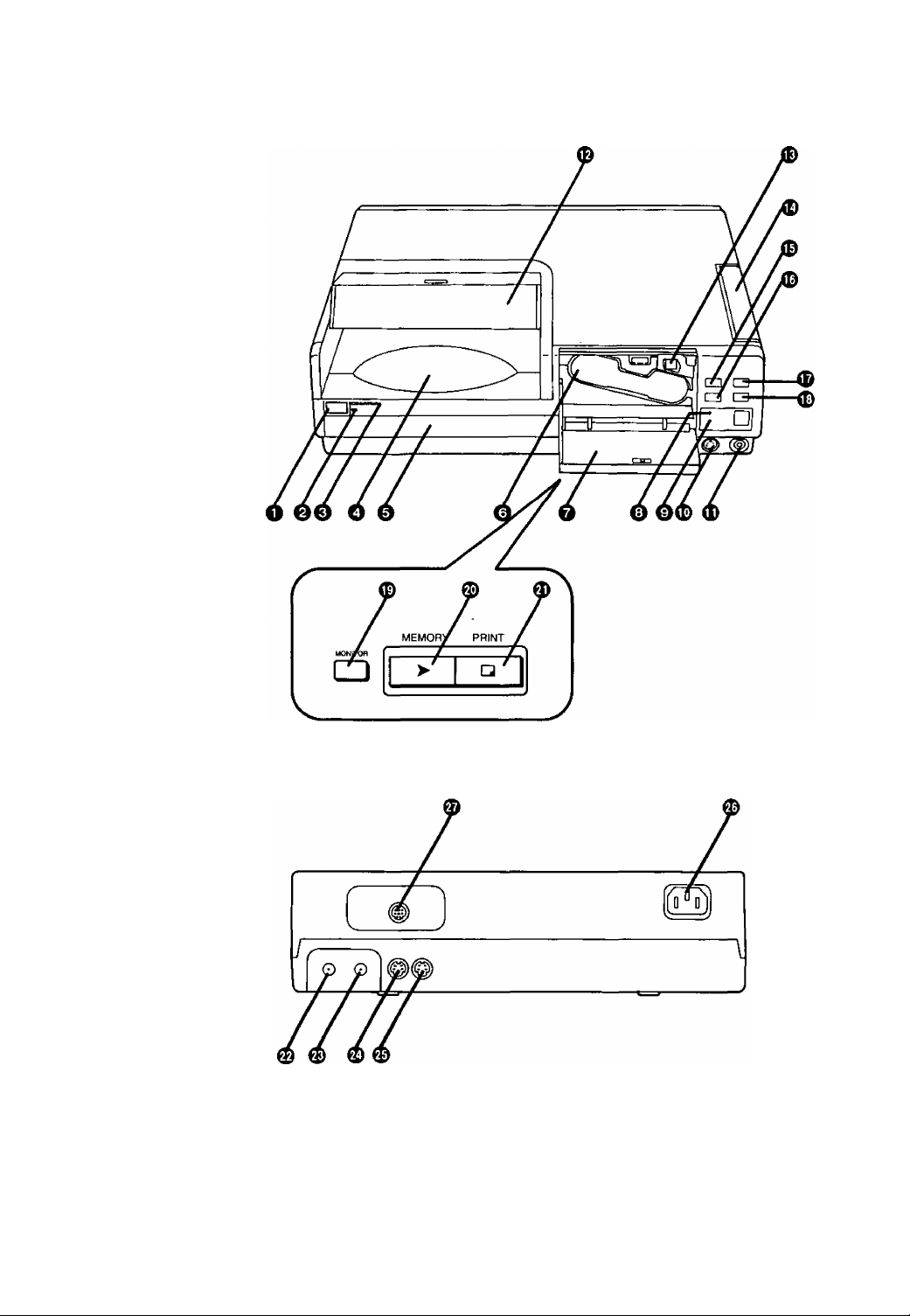
Controls and Components
—
[Front Panel]
[Rear Panel]
Page 5

o [POWER] Button
Q [STAND BY] Lamp
It remains lit as long as the Power Cable is
connected to a wall socket.
0 [POWER] Lamp
It lights when you turn the power on.
O Print Exit
The printed pictures are ejected here.
0 Paper Cassette
The printing paper is stacked here.
0 Ink Cassette Compartment
It holds the Ink Cassette.
0 Ink Cassette Compartment Door
Open this Door to insert or take out the Ink
Cassette.
0 [ERROR] Lamp
It flashes when the paper is jammed or
condensation has formed inside the Printer; at
the same time, a corresponding error message
appears on the TV screen.
0 [PAPER/INK] Lamp
It flashes when the Paper Cassette or the Ink
Cassette is empty; at the same time a
corresponding message appears on the TV
screen.
0 [S-VIDEO] Input Jack on the Front Panel
Connect to video equipment with an S-Video
Output Jack.
(D [VIDEO] Input Jack on the Front Panel
Connect to video equipment with a Video
Output Jack.
0 Print Exit Cover
Open this Cover to take out the paper after
printing.
0 ink Cassette Eject Lever
Push it downward to eject the Ink Cassette.
0 Ink Cassette Side Cover
If paper is jammed, open this Cover to remove
the stuck paper.
0[1SHOT ERASE]/[^] Button
• Every single push of this Button in the
Multi-Print Mode or in the Strobe Mode
erases one picture after another.
• In the Menu Mode or Multi-Print Mode, this
button functions as [◄] Cursor Button.
0[MENU]/[T] Button
• Pressing this Button puts the Printer in the
Menu Mode.
• In the Menu Mode, this button functions as
[▼] Cursor Button.
0[MULTI]/[^] Button
• Use this Button to print a series of different
pictures, all on the same print.
• In the Menu Mode or Multi-Print Mode, this
button functions as [►] Cursor Button.
0[FLD/FRM]/[EXEC] Button
•If the memorized picture is blurred, press this
Button to set to [FLD]. If the memorized
picture is not blurred, press this Button to set
to [FRM].
• In the Menu Mode and Multi-Print Mode, this
button functions as [EXEC] Button.
0 [MONITOR] Button
Use this Button to switch over from the picture
from the external video source unit to the
memorized picture or vice versa.
0 [MEMORY] Button/Lamp
Press this Button while the [MEMORY] Lamp is
lit. This stores the picture from the external
video source unit in memory.
0 [PRINT] Button
Press this Button while the [PRINT] Lamp is lit.
This prints the picture stored in memory.
0 [VIDEO] Input Jack
Connect to video equipment with a Video
Output Jack.
0 [VIDEO] Output Jack
Connect to the Video Input Jack on the TV.
0 [S-VIDEO] Input Jack
Connect to video equipment with an S-Video
Output Jack.
0 [S-VIDEO] Output Jack
Connect to the S-Video Input Jack on the TV.
0 Power Socket
Connect the Power Cable to an AC power
outlet.
0 [EXT.] Jack
Connect the optional Foot Pedal (AG-A2P).
tf)
c
o
CQ
CO
o.
o
Page 6
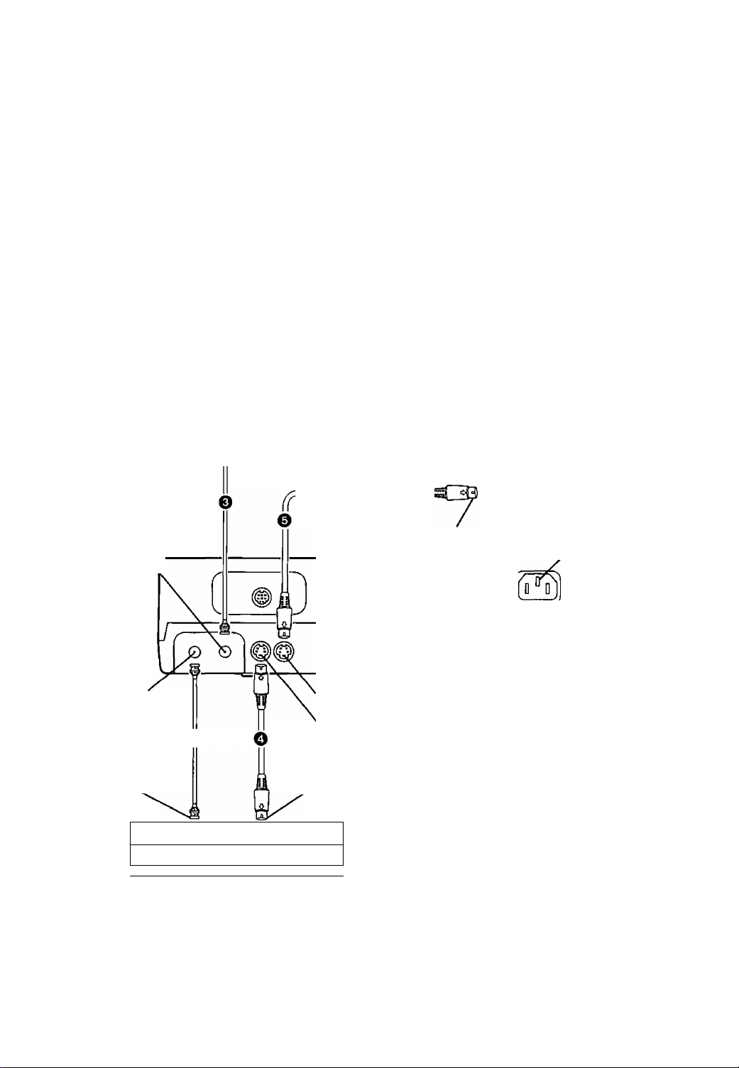
Connection
When Printing Pictures from a VCR etc. That Are
Played Back on a TV Equipped with Video Input
Jacks
•For safety reasons, turn off the power of all units before connecting.
•Select [VIDEO] or [S-VIDEO] for [INPUT] in the Menu Mode according to the type of video input
jack to which the connection is made. (p. 16)
•When connecting to one of the Video Input Jacks on the Front Panel, selecting [VIDEO] or
[S-VIDEO] for the connection on the Rear Panel is not possible, because the connection on the
Front Panel has priority. To select the desired connection on the Rear Panel, disconnect the Video
Cable from the Front Panel.
Connections O, @ and o (Using 2 Video Cables)
Please purchase a suitable Video Cables for connections @ and o, as these cables are not supplied.
<Hint>
When both the VCR and TV are equipped with S-Video Jacks,
Use connections 0,0 ^nd 0 (Using 2 S-Video Cables)
Please purchase suitable S-Video Cables for connections O and 0, as these cables are not
supplied.
[Rear]
To Video Inout Jack TV (optional)
Video Output Jack
V
Video Input Jack
Video Cable (optional) 0
To Video Output Jack
ll— ,
OO y
L ^
VCR or other Video Equipment (optional)
ir
Video Cable (optional)
S-Video Cable (optional)
To S-Video Input Jack
Power Socket
1
S-Video Output Jack
S-Video Input Jack
S-Video Cable (optional)
To S-Video Output Jack
J
(
oooo
_____________
_
Power Cable (supplied)
To AC Power Outlet
(AC 120 V 50/60 Hz)
When the Color Video Printer’s power is off, the picture signal input through the S-Video Input
Jack is output only through the S-Video Output Jack, and the picture signal input through the
Video Input Jack is output only through the Video Output Jack. In both cases, the corresponding
Video Input Jack on the Front Panel has priority. The selection of the Input Jack made in the Menu
Mode has no effect when the power is off.
Page 7
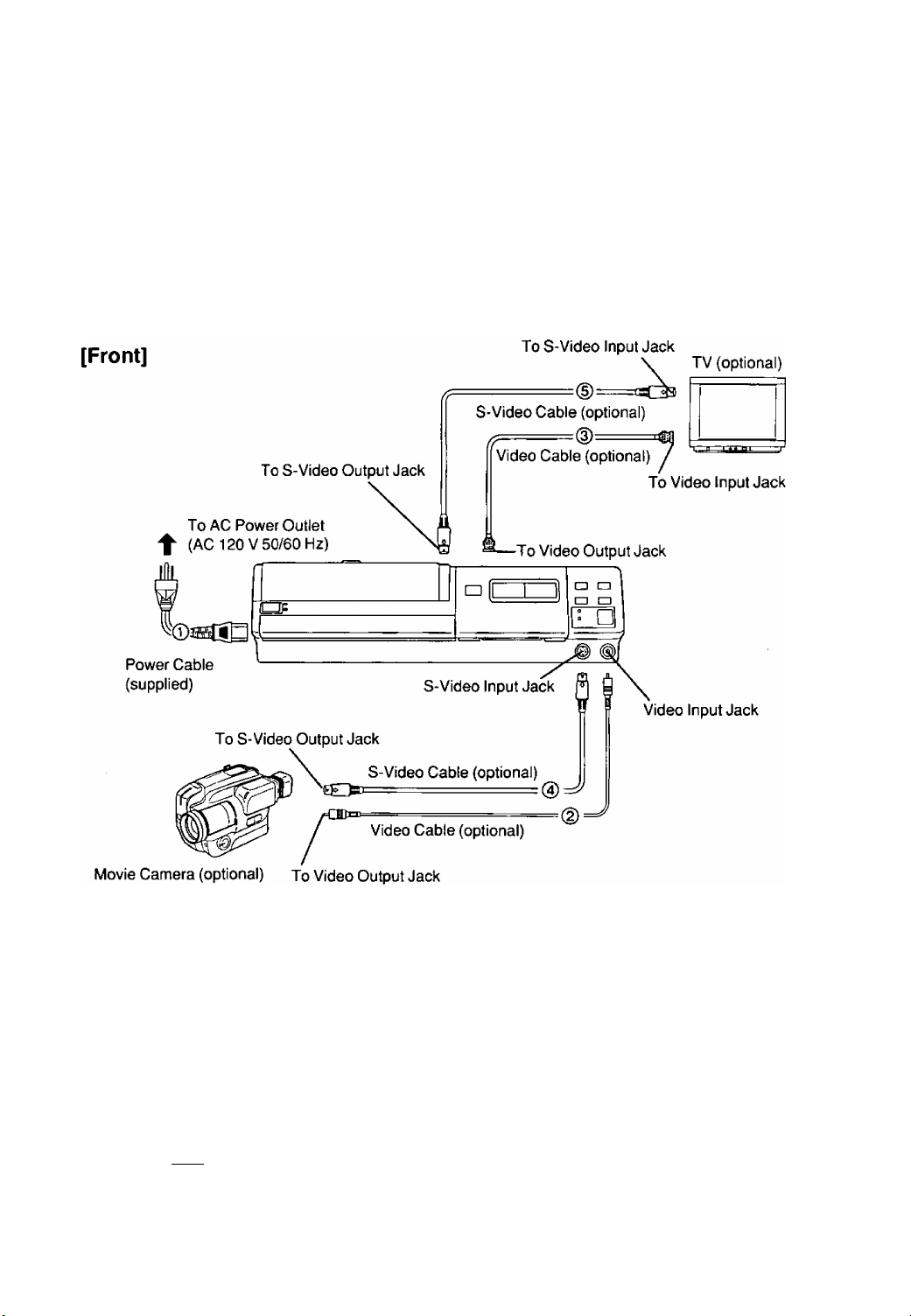
^ When Printing Pictures from a Movie Camera
• In this case, connecting the Movie Camera to a Video Input Jack on the Front Panel is most
convenient.
•Select [VIDEO] or [S-VIDEO] for [INPUT] in the Menu Mode according to the type of video input
jack to which the connection is made. (p. 16)
Connections ©, @ and (3) (Using 2 Video Cables)
<Hint>
When the Movie Camera is equipped with S-Video Jacks,
Use connections ©, 0 and (§) (Using 2 S-Video Cables)
»
c
o
ra
to
a.
Q>
Note for the installation:
As this Printer employs the thermal sublimation transfer printing system, the temperature inside the
unit rises considerably. Be sure to install it in a well-ventilated place.
^ When Performing Remote Control Operation from
External Equipment
■ Remote Control Jack [EXT.]:
Connecting the optional Foot Pedal
AG-A2P to this jack makes possible
[ ® ]
© o
remote-controlled operation of the
Printer.
7
Page 8
^ Title/Purpose
Operations
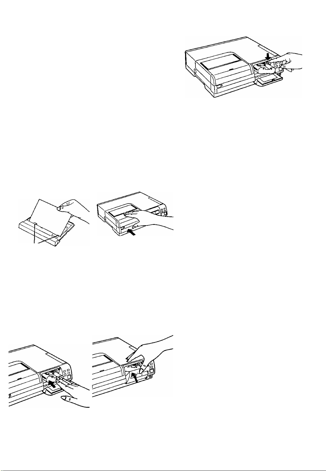
Inserting the Printing
Paper
Inserting the Ink
Cassette
1 Push the Paper
Cassette inward.
•When pushing and then
releasing the Paper
Cassette, it pops out.
1 Open the Ink
Cassette
Compartment Door.
2 Pull it out.
2 Tighten the ink Fiim
in the ink Cassette.
<
_______________________________________________
8
Ink Cassette Compartment Door
• Insert a finger in the spool
and turn in the direction of
the arrow.
•The Ink Cassette is part of
the optional Video Print
Set.
Page 9
r.
Removing the Ink Cassette
Push down the Ink Cassette Eject Lever and
pull the Ink Cassette straight out.
Remarks, etc.
(0
c
g
«
Ip.
to
«
Insert the printing
paper with its printed
markings facing
downward into the
Paper Cassette.
Tabs
•The cassette can hold up
to 25 sheets of normal or
adhesive paper.
• Insert the printing paper
under the two tabs.
Hold the Ink Cassette
so that the recessed
part faces upward
and insert it
completely.
Insert the Paper
Cassette completely.
Close the Ink
Cassette
Compartment Door.
• Do not touch the printing (unmarked) side of
the paper.
• Fan the paper before inserting it into the Paper
Cassette, because several sheets sticking to
each other could cause a paper jam.
• Do not bend or fold the paper or insert it with
the wrong side facing upward. This could
cause malfunction.
•During printing, the Paper Cassette cannot be
removed.
•If the paper is curled and protrudes over the top
edge of the Paper Cassette, remove some
sheets of paper so that the paper fits properly
into the Cassette.
•Do not touch the Ink Film in the Ink Cassette or
try to remove it from the cassette.
•When the Ink Film in the Ink Cassette is used
up, replace it with a new Ink Cassette.
The old Ink Cassette cannot be reused.
• Do not try to remove the label affixed to the Ink
Cassette.
•To obtain good printing quality, use only the
Printing Paper and the Ink Cassette packed
together as a set in the same box.
•For removing the Ink Cassette from the Printer,
refer to the illustration at the top of the page.
Confirm that the Cassette is
completely inserted, before
you close the door.
J
Page 10
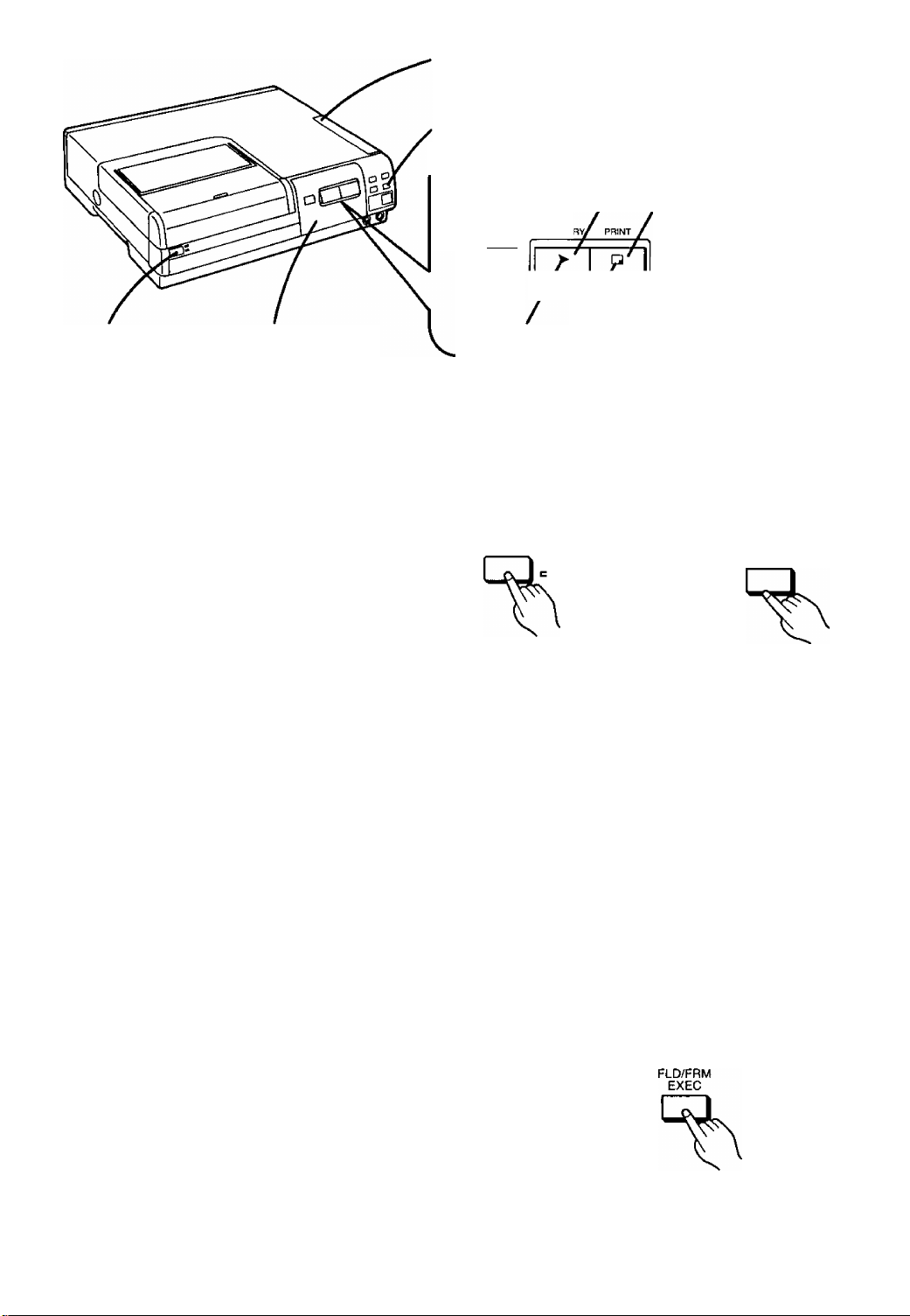
Ink Cassette Side Cover
[FLD/FRM] Button
[POWER] Button
Ink Cassette
Compartment Door
r
Title/Purpose
Normal Printing
•This section explains the basic operations for
printing.
•Before printing, connect the Printer with a VCR,
Movie Camera or/and TV.
r
[MONITOR] Button / [PRINT] Button
MOyOft
[MEMORY] Button
/ MEMOl
LJ
[PRINT] Lamp
[MEMORY] Lamp
Operations
7 Turn the Printer on.
-)ìf4>OWER
STAND SY
2 Select the Video
Input Jack (VIDEO or
S-VIDEO) on the
MENU Screen.
MENU T
►The [POWER] Lamp lights.
• For details about selecting,
refer to "Selecting the Input
Jack (INPUT)’’ oh page 16.
■ Selecting a Field Picture or Frame Picture
Push the [FLD/FRM EXEC] Button to change the picture mode
between the following two modes:
FLD: For printing a picture with fast moving subjects
and when the picture stored in memory is blurred.
(This reduces blurring due to fast movement,
however, the picture quality may be slightly
inferior to that in the FRM Mode.)
£ FRM: For printing a still picture or a moving picture with
little movement.
V.
10
Page 11
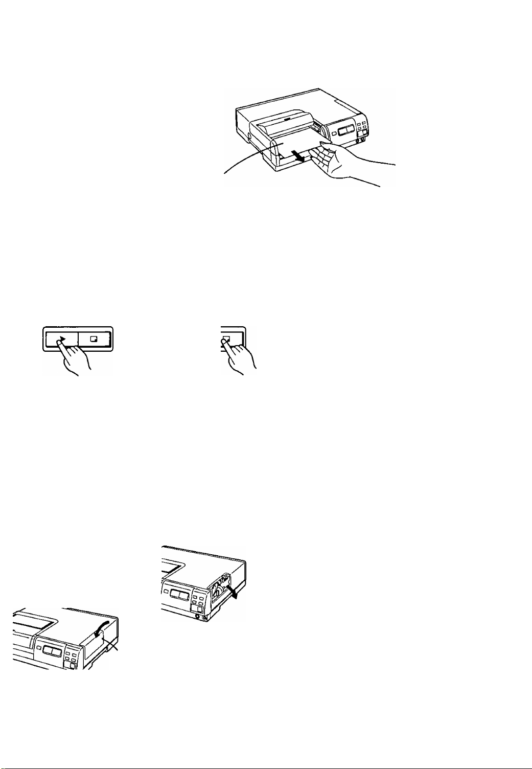
3 Press the [MEMORY]
Button.
MEMOflY PRINT
•The [PRINT] Lamp on the
Printer lights.
•To replace the stored
picture by a new one, press
the [MONITOR] Button,
and then press the
[MEMORY] Button again.
If the Paper Gets Jammed
1 Turnthepoweroff and
unplug the Power Cable
from the wall outlet.
2 Open the Ink Cassette
Compartment Door and
remove the Ink Cassette.
3 Open the Ink Cassette
Side Cover,
■ After Printing
Take out finished the prints as shown in the illustration below.
•To prevent paper jam, do not let more than 10 finished prints accumuiate in the
Print Exit.
Print Exit
Remarks, etc.
Press the [PRINT]
Button while the
[PRINT] Lamp is lit.
MEMORY PRINT
»Printing starts.
►When printing is finished,
the picture from the source
unit appears again on the
TV screen.
Pull out the paper from the
Ink Cassette
Compartment.
•The [1 SHOT ERASE] Button and the
[MEMORY] Button do not work during printing.
•Printing two or more pictures continuously or
printing in low or high temperature may take
more time.
• Do not try to take out the Paper Cassette and
the Ink Cassette during printing. To do so
would halt printing and could cause paper jam
or a defect of the unit.
•Do not pull on the printing paper while it is still
moving during printing. This could cause
malfunction of the unit.
•If the Printer becomes hot, the edge of the
printed pictures could become slightly
discolored.
Hints for Use
• If you press the [MONITOR] Button during
printing, the picture from the source unit
appears again on the TV screen and you can
search for the next picture to be printed.
•After printing is finished, you can print the same
picture one more time simply by again pressing
the [MONITOR] Button so that the stored
picture appears on the TV screen, and then
pressing the [PRINT] Button.
•During printing (when the selected number of
prints is 2 or more), the following message
appears:
[MENU] PRINT STOP
»
CO
0>
Q.
o
tf)
CO
CQ
•Turn the screw
counterclockwise with a
screwdriver to open the
Cover.
Screw
•Pull out the jammed paper
from the Ink Cassette
Compartment Door or from
the opened Ink Cassette
Side Cover.
If you press the [MENU] Button, printing will
stop after the printing of the present print is
finished, and all further selected prints are
canceled.
11
Page 12
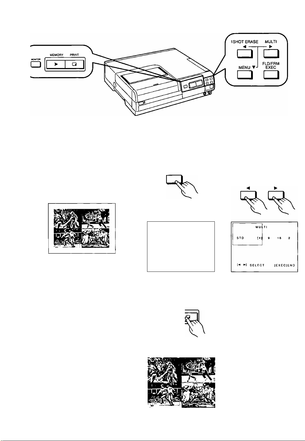
r
Title/Purpose
Operations
Printing a Series of
Different Pictures on
the Same Print
(Multi Print)
This printing function allows you to divide the
screen into 2, 4,9 or 16 mini-frames, fill them
with different pictures and print them together on
the same print.
1 Press the [MULTI]
Button.
MULTI
►
>The screen is divided into a
number of mini-frames.
M U LT I
STD
(-* ►] SELECT lEXEClEND
4 g
(161 2
5 Press the [PRINT]
Button.
MEMORY PRINT
2 Press the [◄] or the
[^] Button to select
the desired number
of mini-frames.
1 SHOT ERASE MULTI
12
• Printing starts.
Page 13

Press the [EXEC]
Button.
4 Press the [MEMORY]
Button.
MEMORY PRINT
Remarks, etc.
•When [DIVIDE], [ZOOM] or [STROBE] has
been selected for the [FORMAT] on the MENU
Screen (p.18), the [MULTI] Button does not
work.
o
ffi
V)
CO
h.
0)
Q.
u
cn
to
► Each press of this Button
stores the picture currently
displayed on the TV screen
in a mini-frame.
■ To Cancel Stored Pictures
Press the [MONITOR] Button to display the
stored pictures on the TV screen, and then press
the [1 SHOT ERASE] Button.
Every push of this Button erases one stored
picture starting with the last one.
To store a new picture in place of an erased one,
press the [MONITOR] Button again.
13
Page 14

r
Title/Purpose Operations
Using the Menu Mode
The Menu Mode can be used to display the
MENU on the TV screen and to select functions
as well as the Input Jack being used.
■ How to Use the Operation
Buttons for the MENU Screen
When you press the [MENU] Button, the MENU
Screen appears on the TV screen.
The following 4 buttons now function as Cursor
buttons and Execution Button for selecting items
on the MENU Screen.
1 SHOT ERASE MULTI
MENU T-l
— ►
FLD/FRM
EXEC
7 Press the [MENU]
Button.
MENU T
•The MENU Screen appears
on the TV screen.
MENU
► PRINT Q'TY : 1
INPUT : 1 VIDEO ] S-VIDEO
FORMAT :|STD) SET
VIDEO ADJ :[STD] SET
SET UP :|OFF) SET
[-<»►1 SELECT
O P^int Quantity
(PRINT Q’TY):
© Input Jack
Selector
(INPUT);
[EXEC]END
2 Press the [T] Button
to select the desired
item.
MENU ▼
•The ► Cursor indicates the
selected item.
MENU
PRINT O'TY 1
►INPUT
FORMAT
VIDEO ADJ
SET UP
[-<▼►1 SELECT
Select the desired number of prints
(max. 10) with the [◄] or the [►] Button.
Select with the [◄] or the [►] Button.
[VIDEO]: When connecting the video
source unit to the Video Input
Jack
[S-VIDEO]: When connecting the video
source unit to the S-Video
Input Jack
: [VIDEO] S-VIDEO
:|STD) SET
:|STO] SET
MOFF)
SET
[EXECjEND
• In the Menu Mode, the functions of these
4 buttons are as indicated by the symbols in
shaded boxes under the names of the buttons.
14
Format
©
(FORMAT):
Picture Quality
o
(VIDEO ADJ):
Set-Up
©
(SETUP): Screen appears on the TV screen.
After selecting [SET], you can select one
of five different printing modes with the
[▼] Button.
After selecting [SET], you can adjust the
picture quality.
When you select [SET], the SET UP
Page 15

Press the [◄] or the
[^] Button to select
the desired setting.
1SHOT ERASE MULTI
•The selected setting is
indicated by [ ].
MENU
PRINT Q'TY 1
► INPUT : VIDEO [SVIDEO]
FORMAT :[STD] SET
VIDEO ADJ :[STD] SET
SET UP :10FF] SET
["«▼H SELECT
lEXEClEND
•The MENU Screen
disappears fronn the TV
screen.
MENU
Press the [EXEC]
Button to complete
the setting.
Remarks, etc.
»The [MENU] Button does not work during
printing.
»While the MENU Screen Is displayed on the TV
screen, the [MEMORY], [PRINT] and
[MONITOR] Buttons do not work.
»When you select a printing mode on the
FORMAT Screen, the selected function is
displayed for the item “FORMAT” on the
MENU Screen instead of [STD].
»When you select a desired picture quality on
the VIDEO ADJ Screen, [ADJ] is displayed for
the item “VIDEO ADJ" on the MENU Screen
instead of [STD]. The selected setting will be
maintained until you select a different setting
on the VIDEO ADJ Screen.
►The Cursor Buttons corresponding to the
triangle marks shown at the bottom of the
MENU Screen (◄▼►) can be used.
o
T3
T3
<
•t-l
a>
c
o
CO
w
o
Q.
0)
0
c
01
>
a
0^
-►PRINT Q'TY
— INPUT
— FORMAT
VIDEO ADJ
SET UP
SELECT
1
[VIDEO]
[STD]
[STD]
[OFF]
S-VIDEO
SET
SET
SET
[EXECJEND
15
Page 16

Title/Purpose Operations
Selecting the Number
of Prints
(PRINT Q’TY)
A maximum 10 prints can be selected for one
printing cycle.
Selecting the Input
Jack
(INPUT)
1 Press the [MENU]
Button.
MENU T
►The MENU Screen appears
on the TV screen.
MENU
► PR I NT Q'TY t 1
INPUT
format
VIDEO ADJ :[STD) SET
SET UP
(■*»►1 SELECT
:[«)EOl S-VTOEO
:[STD] SET
;[OFF) SET
[EXECJEND
1 Press the [MENU]
Button.
MENU Y MENU Y
2 Select [PRINT Q’TY].
MENU
► PRINT Q'TY : 1
INPUT ! [VIDEO] S-VIDEO
FORMAT ![STD] SET
VIDEO ADJ :[STD] SET
SET UP :[OFF] SET
[^▼►) SELECT lEXEClEND
2 Press the [▼] Button
to select [INPUT].
Perform these steps to select the Input Jack
[VIDEO] or [S-VIDEO] to which the source unit is
connected.
16
MENU
► PRINT Q'TY 1
INPUT
format
VIDEO ADJ :[STD) SET
SET UP
: [ VIDEO I SVIOEO
;[STDl
:[OFF) SET
SELECT [EXECJEND
SET
MENU
PRINT Q'TY
►INPUT
format
VIDEO ADJ :[STD) SET
SET UP :[OFF] SET
!-•*►) SELECT [EXECjEND
: 1
:| VIDEO) S-VIDEO
:[STD) SET
Page 17

Press the[^]orthe
[^] Button to select
the number of prints
desired.
1SH0T ERASE
<4
MENU
► PRINT Q'TY : 5
INPUT : VCEO [5-VDEO]
FORMAT :tSTO) SET
VIDEO ADJ :[STD)
SET UP :[OFF) SET
[-«’►I select |EXEC)END
SET
Press the [EXEC]
Button.
►This terminates the Menu
Mode.
Remarks, etc.
•The number of prints can be selected between
1 and 10.
• If the desired number of prints is set to 2 or
more, the number is automatically reset to 1
when printing is finished.
о
■о
TJ
<
(Л
c
о
г а
ь.
0>
О.
0>
о
с
л
>
Press the[^]orthe
[P>] Button to select
the Input Jack being
used.
1 SHOT ERASE MULTI
^ ►
MENU
PRINT 0 TV
►INPUT : VIDEO [S-VlDEO]
FORMAT
VIDEO ADJ :[STO) SET
SETUP :10FF) SET
: 1
:[STD) SET
SELECT [EXEC]END
4 Press the [EXEC]
Button.
►This terminates the Menu
Mode.
■ Selecting the Input Jack
•Select [VIDEO] when the picture signal is input
through the Video Input Jack, and select
[S-VIDEO] when the picture signal is input
through the S-Video Input Jack.
• If the Input Mode selected on the MENU
Screen is different from the actually connected
Input Jack, no picture is displayed.
•If connections are made to Input Jacks on both
the Front and Rear Panels, the Input Jack on
the Front Panel has priority. {The Input Jacks
on the Front Panel are also selected with the
setting made on the MENU Screen.)
17
Page 18

r
Title/Purpose Operations
Selecting the Printing
Format
(FORMAT)
You can select from among several printing
modes.
STD: For normal printing
MULTI: For printing a sequence of different
pictures on the same print
DIVIDE: For printing the same picture on
the same print
ZOOM: For printing an enlarged part of a
picture
STROBE: For printing a sequence of pictures
taken a intervals from a scene on
the same print
|T| Printing a Sequence
of Different Pictures
on the Same Print
(MULTI)
t Press the [MENU]
Button.
MENU ▼
MENU
► PR 1 NT Q'TY : 1
INPUT : [ VIDEO 1
format :(ST0]
VIDEO ADJ :|STO| SET
SET UP :[OFF) SET
[■<»►1 SELECT [EXEC]END
S-VIDEO
SET
1 Press the [T] Button
to select [MULTI] on
the FORMAT Screen.
MENU T
Press the [T] Button
to set the ► Cursor
to [FORMAT].
MENU ▼
ME NU
PR IN T Q T V 1
IN PU T
► F OR MA T :I ST D| SE T
VI DE O A DJ
SE TU P
[■ < ▼ ► 1 S ELE CT
:[ VIDEO)
:1 ST D) S ET
:1 0F F] S ET
(E XE C)E ND
Press the[^]orthe
[^] Button to select
the desired number
of mini-frames.
1 SHOT ERASE
S-VIDEO
18
FO P
MAT
ST O
► MULTI : I 4
DIVIDE
ZO OM
STROBE
[^▼►1 SELECT [EXECIENO
d 16 2
----------
ST D
► M UL TI
DI VI DE
ZO OM
ST RO BE
(^▼►1 SELECT [EXECJEND
: 4 9 [16] 2
Page 19

3 Press the [^] Button
to select [SET].
•The FORMAT Screen
appears on the TV screen.
To display the picture
from the source unit
again, press the [EXEC]
Button.
►This terminates the Menu
Mode.
Remarks, etc.
►When you select a printing mode on the
FORMAT Screen and return to the MENU
Screen, the selected function is displayed
there.
MENU
P R1 NT Q TY : 1
INPUT :[V1DE0) S-WOEO ■
► FORMAT :[MULT 1 SET
VIDEO ADJ ![STD] SET
SET UP i[OFF] SET
!••»•■) SELECT (EXEC)END
Example of the [FORMAT] Screen after
changing the setting from [STD] to [MULTI].
v>
c
_o
o
Q.
o
T3
0>
u
c
(0
>
■O
<
3 Press the [EXEC]
Button.
►This terminates the Menu
Mode.
4 Press the [MEMORY]
Button.
MEMORY PRINT
• Each press of this button
stores the currently
displayed picture in a
mini-frame starting at the
upper-left corner.
■ To Print the Multi-Picture
Sequence
When all mini-frames have been filled with
pictures, the [PRINT] Lamp lights. To start
printing, press the [PRINT] Button.
■ To Cancel Stored Pictures
Press the [MONITOR] Button to display the
stored pictures, and then press the [1 SHOT
ERASE] Button to erase them. Every push of this
Button erases one stored picture starting with
the last one. To store a new picture in place of an
erased one, press the [MONITOR] Button again.
19
Page 20

r
Title/Purpose Operations
^ Printing the Same
Picture Repeatediy
on the Same Print
(DIVIDE)
^ Printing an
Enlarged Part of the
Picture
(ZOOM)
Press the [T] Button
to set the > Cursor
to [DIVIDE] on the
FORMAT Screen.
MENU ▼
FOAM AT
STD
MULTI
► DIVIDE ; [4]
ZOOM
STROBE ..
[-*’'►1 SELECT
9 t 6
|EXEC)END
Press the [▼] Button
to set the > Cursor
to [ZOOM] on the
FORMAT Screen.
MENU T
Press the[^l or the
[^] Button to select
the desired number.
1 SHOT ERASE MULTI
< >
FORM
STD
MULT
► DI VI D
E : 4
E
SELECT
1 116)
|EX LCJEND
ZOOM
STROt
2 Press the [EXEC]
Button.
20
STD
MUtTi
DIVIDE
► ZOOM
STROBE
[▼1 SELECT [EXEC)END
►This terminates the Menu
Mode.
Page 21

Press the [EXEC]
Button.
4 Press the [MEMORY]
Button.
MEMORY PRINT
Remarks, etc.
► It is also possible to select the number of
mini-frames for [DIVIDE] in the Menu Mode
after storing the picture you want to print.
O
T3
■o
<
o
O)
V)
c
o
ra
u
a.
o
c
>
►This terminates the Menu
Mode.
3 Press the [MEMORY]
Button.
MEMORY PRINT
•The center part of the
picture is enlarged to
approx, twice its size for
printing.
•When using the Infrared
Remote (optional), the
enlarged part of the stored
picture can be moved in
any of the 4 directions.
5 Press the [PRINT]
Button.
MEMORY PRINT
»Printing starts.
4 Press the [PRINT]
Button.
MEMORY PRINT
• Enlarging the original picture may cause the
resulting print to become somewhat grainy.
• It is also possible to select [ZOOM] in the Menu
Mode after storing the picture you want to print.
•The ZOOM Function lets you make an
enlarged print of each quarter of the stored
picture, so you can assemble the prints for a
blow-up of the original picture.
21
Page 22

1 SHOT ERASE MULTI
<
--------
Title/Purpose Operations
------
►
[4] Printing a Sequence
of Pictures Taken at
Fixed Intervals on
the Same Print
(STROBE)
This printing function allows the screen to be
divided into 4, 9 or 16 mini-frames, which you
can then fiil sequentialiy with freeze-frames
taken at fixed intervals.
Press the [T] Button
to set the ^ Cursor
to [STROBE] on the
FORMAT Screen.
MENU ▼
5 Press the [T] Button
to set the ^ Cursor
to [SPEED].
MENU ▼
Press the[^] or the
[>-] Button to select
the desired number.
1SHOT ERASE MULTI
6 Press the [◄] or the
[P>] Button to select
the desired strobe
speed.
1SHOT ERASE MULTI
22
STD
MULTI
DIVIDE
ZOOM
STROBE
-----------
MODE
► SPEED : IL)
SELECT
[EXECjEND
Page 23

3 Press the [▼] Button
to set the ^ Cursor
to [MODE].
MENU T
4 Press the [◄] or the
[^] Button to select
the desired mode.
1SHOT ERASE MULTI
Remarks, etc.
■ To Erase Stored Pictures
•You can erase unwanted pictures in the
sequence by pressing the [1 SHOT ERASE]
Button. Every push of this Button erases one
stored picture starting with the last one.
• If you want to store a different strobe sequence
of pictures, after having stored a sequence
already, press the [MONITOR] Button to
display the picture from the source unit and
then press the [MEMORY] Button to store the
new sequence.
Hint for Use
If you press the [MONITOR] Button after printing,
the stored sequence of pictures reappears on
the TV screen and can be printed again.
(However, it is no longer possible to change
pictures of the sequence by using the [1 SHOT
ERASE] Button.
O
■o
TJ
<
(A
c
o
B
a>
a.
o
u
c
a
>
7 Press the [EXEC]
Button.
>This terminates the Menu
Mode.
8 Press the [MEMORY]
Button.
MEMORY PRIWT
•This stores the strobe
sequence of pictures in
memory.
■ Notes about the Strobe Mode
[NORM]: The pictures are taken and stored
in memory at uniform intervals.
[SWING]: The intervals become shorter
towards the middle of the sampling
period and then become longer
again towards the end of it. This
mode is ideal for motion analysis
prints of golf swings, tennis serves,
etc.
23
Page 24

Title/Purpose Operations
Adjusting the Picture
Quality
(VIDEO ADJ)
For optimum printing results, it is recommended
to adjust the quality of the stored picture.
1 Press the [MENU]
Button.
MENU ▼
►The MENU Screen
appears on the screen.
MENU
► PRINT Q TV ; 1
INPUT :[VDEO] S-V(DE0
FORMAT :[STDj SET
VIDEO ADJ :(STD) SET
SETUP (OFF] SF T
(•*»►1 SELECT [EXEC]END
5 Press the [<] or the
[^] Button to adjust
as desired.
1SHOT ERASE MULTI
2 Press the [▼] Button
to set the ^ Cursor
to [VIDEO ADJ].
MENU ▼
MENU
PR 1 NT Q TV ; 1
INPUT ;|V10e0|
format :(ST0]
► VIDEO ADJ ;|STO] SET
SET UP r(OFF] SET
[^▼►1 SELECT
S-VIDEO
SET
[ E X E C) E N D
6 After the adjustment,
press the [EXEC]
Button.
24
VIDEO ADJ
STD
► COLOR -| —
TINT 0
BRIGHT 0
SHARPNESS: L [M] H
SELECT [EXEC]END
-----------
1—h
Page 25

■ To Achieve Optimum Picture Quaiity
1 Select [STD] for [VIDEO ADJ] on the MENU Screen and print a colorful picture
that contains both bright and dark parts.
2 Use the picture controls on the TV set to adjust the colors on the screen so that
they match the colors of the trial picture printed in step 1.
3 Adjust the picture quality items on the [VIDEO ADJ] Screen to obtain the desired
picture quality.
Press the [^] Button
to select [SET].
►The VIDEO ADJ Screen
appears on the screen.
MENU
PRINT O'TY 1
tN PUT
format
► VIDEO ADJ : STD (SET)
SET UP :[OFF) SET
:|VI0e01 SVCEO
:|STD]
SELECT
SET
[EXECIEND
Press the [▼] Button
to select the picture
quality Item that you
want to adjust.
MENU ▼
Remarks, etc.
■ Picture Quality Adjustment
Items
[STD]: Standard setting of the picture
quality. In this setting, adjusting
the picture quaiity is NOT
possible.
[COLOR]: This lets you adjust to the
desired color intensity.
Adjustment is possible between
-9 and +9. (When set to -9,
the printed picture is in black
and white.)
[TINT]; This lets you adjust to the
desired color tint. Adjustment is
possible between -9 and +9.
Adjusting to the right produces
a greenish picture; adjusting to
the left produces a reddish
picture.
[BRIGHT]: This lets you adjust to the
desired balance of brightness
and depth. Adjustment is
possible between —9 and +9.
[SHARPNESS]: This lets you adjust the picture
contours.
L; For soft picture contours
M; For normal picture contours
H; For sharp picture contours
O
•o
■O
<
c
o
(0
k_
0)
Q.
<u
o
c
CD
>
•Changing the setting of [SHARPNESS] does
not change the appearance of the picture on
the TV screen. Use a printed picture to judge
and adjust the setting.
25
Page 26

Title/Purpose Operations
Setting Up Special
Functions
(SET UP)
The following items can be set up:
•Selecting ON or OFF for Mirror Reverse
Printing
•Selecting ON or OFF forthe grid lines on multi
prints
•Selecting On or OFF for the On-Screen Display
1 Press the [MENU]
Button.
MENU T
»The MENU Screen
appears on the TV screen.
WIENU
► PRINT O'TY 1
INPUT
FORMAT :(STD] SET
VIDEO ADJ :[STD]
SET (JP :[OFF] SET
[^»►1 SELECT
) Press the [◄] or the
[^] Button to select
[ON] or [OFF].
1 SHOT ERASE MULTI
:|V10EO) S-VIOEO
SET
[EXEC]END
Press the [T] Button
to set the ^ Cursor
to [SET UP].
MENU T
MENU
PRINT Q *T Y
INPUT : I VIDEO) S-VIDEO
FORMAT :[STD] SET
VIDEO ADJ
► SET UP HOFF]
(■•’►) SELECT
1
:(STD] SET
[EXECJEND
After setting up is
finished, press the
[EXEC] Button.
SET
26
Page 27

Press the [^] Button
to select [SET].
►The SET UP Screen
appears on the TV screen.
MENU
PRINT OT Y 1
INPUT
format
VIDEO ADJ i(STD] SET
► SET UP
[■*»►] SELECT
:[VOEO)
:(STOl SET
; OFF (SET)
[EXECjEND
s-v ee o
Press the [T] Button
to select the item that
you want to set up.
MENU-T
SET UP
► MIRROR REV : [OFF] ON
GRID LINE : [OFF] ON
OSD :[OFFJ
EXT REMOTE : [A] R
SELECT [EXECJEND
C D
ON
Remarks, etc.
■ Set-Up Items
[MIRROR REV]: When set to [ON], the stored
picture is printed image
reversed (like a picture
reflected in a mirror).
However, the picture on the
screen is not reversed.
[GRID LINE]: When set to [ON], the mini
frames of the print made in
the Multi-Print Mode are
separated by grid lines.
However, the grid lines are
not displayed on the screen.
[OSD]: When set to [OFF], the On-
Screen Indications are
canceled.
[EXT REMOTE]: When the optional Foot
Pedal (AG-A2P) is
connected, any of the four
operation mode settings can
be selected.
O
■D
T3
<
cn
c
o
CO
0>
a.
V
o
c
to
>
27
Page 28

r
Title/Purpose Operations
Selecting the
Operation Mode of
the External Remote
Controller
(EXT REMOTE)
With these operation steps, you can select the
operation mode for the optional Foot Pedal.
■ Using the External Remote
Controller
The optional Foot Pedal makes it possible to
store and print pictures with simple foot
operation.
Press the (T) Button
to set the cursor to
[EXT REMOTE] on
the SET UP Screen.
MENU T
SET UP
Ml RROR RE V : OFF
WHITE BAR : (OFF]
OSD i(OFF[
► EXT REMOTE : [A) B
SELECT (EXECIEND
[OMI
ON
ON
7 Connect the Foot
Pedal to the [EXT.]
Jack on the Printer’s
rear panel.
2 Press the (◄) or (►)
Button to select the
desired remote
operation mode.
1 SHOT ERASE MULTI
2 Turn on the power.
28
Page 29

After set-up is
finished, press the
[EXEC] Button.
FLD/FRM
EXEC
Operate the Foot
Pedai.
►The function of the
[MEMORY/1SHOT
ERASE] and [PRINT/
MULTI] Pedals differs
depending on the setting
described on the right.
■ Possible Operation Modes
Depending on the operation mode selected for the Foot Pedal, the functions
of its [MEM0RY/1SH0T ERASE] Pedal and [PRINT/MULTI] Pedal are
different.
Normal Printing
[A] [B] [C] [D]
storing in
Memory
Returning to
Picture from
External
Source
Printing
Multi-Printing
Changing the
Number o1
Mini-frames
Storing in
Memory
Returning to
Picture from
External
Source
Storing Next
Picture In
Memory
Returning to
Memory
Picture
Erasing
Stored
Picture from
Memory
Printing Push
Push
IMEMORY/
1SH0T ERASE]
Pedal.
Push
[PRINT/MULTI]
Pedal.
. [A]
Push
[MEMORY/
1 SHOT ERASE]
Pedal.
Returns
automatically.
Push
[MEMORY/
1 SHOT ERASE]
Pedal.
[PRINT/MULTI]
Pedal.
Push
[MEMORY/
ISHOT ERASE]
Pedal.
Push
[MEMORY/
ISHOT ERASE]
Pedal for more
than one second.
Push
[PRINT/MULTI]
Pedal.
Push
[MEMORY/
ISHOT ERASE]
Pedal.
Push
(MEMORY/
ISHOT ERASE)
Pedal for more
than one second.
Push
[MEMORY/
ISHOT ERASE]
Pedal.
[B] [C] [D]
Push
[PRINT/MULTI]
Pedal while
picture from
external source
is displayed but
not yet stored in
memory.
Push
[MEMORY/
ISHOT ERASE]
Pedal.
Push
[MEMORY/
ISHOT ERASE]
Pedal.
Push
[MEMORY/
ISHOT ERASE]
Pedal.
Push
[MEMORY/
1 SHOT ERASE]
Pedal for more
than one second.
Push
[PRINT/MULTI]
Pedal.
Push
[MEMORY/
1 SHOT ERASE]
Pedal,
Push
[MEMORY/
ISHOT ERASE)
Pedal.
Push
[MEMORY/
1SH0T ERASE]
Pedal.
Push
(MEMORY/
ISHOT ERASE]
Pedal for more
than one second.
Push
[MEMORY/
ISHOT ERASE]
Pedal after
storing picture in
memory is
completed.
Push
[MEMORY/
1SH0T ERASE)
Pedal,
Push
[MEMORY/
ISHOT ERASE)
Pedal for more
than one second.
Push
[MEMORY/
ISHOT ERASE]
Pedal.
Push
[MEMORY/
ISHOT ERASE]
Pedal.
Push
[MEMORY/
ISHOT ERASE]
Pedal.
{Returns
automatically
when Storing in
Memory)
Push
[MEMORY/
ISHOT ERASE]
Pedal.
Push
[MEMORY/
ISHOT ERASE]
Pedal for more
than one second.
Push
[MEMORY/
-ISHOT ERASE]
Pedal for more
than one second.
Push
[MEMORY/
ISHOT ERASE]
Pedal after
storing picture in
memory is
completed.
v>
c
(0
0>
Q.
o
■D
<1>
u
c
CO
>
■D
<
29
Page 30

Remote Control Operation from External Equipment
Remote-controlled operation is possible by controlling the TTL level of the [EXT.] Jack or with a mechanical
switch. For more details, contact your Panasonic dealer or Panasonic directly.
Pin No.
1 GND
2
3
4 BUSY Out
5 +5V Out
6 ERROR
7
8
Pin No.
Function
MEMORY In Memory
PRINT In Print
OSD OFF In Turns the OSD off
In/Out Explanation of Function
GROUND
Busy information of the Printer
Output of+5 V
(Output resistance: 2200)
Out Error indication
2 ^^ 1
Input/Output Timing
Name of Pin
MEMORY
PRINT
OSD OFF OPEN
(When OSD is set to “ON” on the Printer’s
Menu Screen)
BUSY
ERROR
30
OPEN
GND
GND
+ 5V
OV
Normal status
No error
OSD ON -
MEMORYON
PRINT ON
OSD OFF
Printer is —
busy.
Error exists.
More than 100 ms
OSD ON
Normal status
No error
Page 31

Precautions for Safety
(Be sure to read this chapter completely.)
■ Please read the following explanations
carefully before using this Color Video
Printer to ensure correct and safe operation.
■ Keep these Instructions handy for later
reference, in case you want to look up
something in the future.
Placement
•Place the Printer on a stable,horizontal surface.
Do not place any heavy object on it, because it
could unbalance the Printer and cause it to drop.
This could result in damage to the Printer and
serious injury to persons.
If the Printer has dropped, turn off the power and
unplug the Power Cable, then contact your dealer.
Continuing to use it in damaged condition is
dangerous as it poses the risk of fire or electric
shock.
•Do not step on the Printer. Especially, pay close
attention that children do not step on the unit and
damage it.
•Keep water and other liquids away from the
Printer. Never place a filled flower vase or drinking
glasses on it. If liquids are spilled into the Printer, it
could cause a fire or electric shock.
If some liquid has spilled into the Printer, turn off
the power and unplug the Power Cable, then
contact your dealer. Continuing to use it in that
condition is dangerous as it poses the risk of fire or
electric shock.
• Do not place small metal objects or flammable
material on the Printer. Also, do not insert any
metal object or flammable material through the
ventilation holes or into the Ink Cassette
Compartment. Especially, pay close attention to
this where the Printer is in reach of little children.
Inserting an object into the unit could cause a fire
or electric shock.
If an object is inserted in the unit, turn off the
power and unplug the Power Cable, then contact
your dealer. Continuing to use it with the object
inside is dangerous and could cause a fire or
electric shock.
•Do not obstruct the ventilation holes (located on
the top, left, right and rear side of the unit) with soft
material such as cloth or paper. This could trap the
heat inside the unit and could cause a fire.
•To prevent the risk of fire or electric shock, never
place the Printer in the following kind of places:
• Narrow places with insufficient ventilation. (A
cooling fan is installed inside the Printer on the
right side and the rear side. However, to cool it
more effectively, leave a space of 10 cm
between the left side, right side, the rear and the
top of the Printer and surrounding objects.)
•On a carpet or bed.
•Near heaters or strong spotlights.
•Places with oily smoke, high humidity and dust.
•Places exposed to direct sunlight for a long time.
Power Cable and Connection to Wall Outlet
•Do not operate the Printer with any other than the
specified power source and voltage (AC 120 V).
To do so could cause a fire or electric shock.
Make sure that the correct power source and
voltage are used before connecting the Power
Cable.
•Do not connect the Power Cable with wet hands. It
could cause electric shock and is very dangerous.
•Using the Printer with a damaged Power Cable is
dangerous and could cause a fire or electric
shock. Be sure to observe the following points:
• Do not make any alteration to the Power Cable.
• Do not place anything heavy on it or expose it to
sharp edges or pointed objects.
• Do not place it near a heater or some other hot
object.
• Do not bend it excessively or twist and yank it.
•Always grasp the plug to connect to or
disconnect it from a wall outlet. Yanking the
cable could damage it.
• If the Power Cable is damaged (if the core is
bared, broken, etc.), be sure to consult your
dealer. Continuing to use a damaged Power
Cable is dangerous and could cause a fire or
electric shock.
O
■o
■O
<
CO
c
o
CO
o
Q.
0>
u
c
to
>
31
Page 32

Precautions for Safety
(Cont’d)
Cautions for Use
Modifying or Disassembling the Color Video Printer
•Never remove the cabinet and never try to modify
or disassemble the Printer. This could cause a fire
or electric shock. For checking, adjustment and
repair of internal parts, consult your dealer.
In Case of Abnormal Operation
If the Printer emits smoke or an unusual smell,
immediately turn off the power and disconnect the
Power Cable from the wall outlet. Make sure that
the smoke stops and then have your dealer check
and, if necessary, repair the Printer. Do not try to
repair it yourself, because it is dangerous.
Pay Attention to Children
• Prevent them from putting their hands into
openings of the Printer such as the Ink Cassette
Compartment. It could cause an electric shock.
•Caution them against stepping on the Printer, or
hanging on to it. It could cause serious damage
and injury.
• Prevent them from inserting small objects into the
ventilation holes. It could cause a fire or electric
shock.
Precautions for Chemicals
• Be careful not to expose the Printer to insecticide
spray or volatile solvent such as benzine and
thinner. They could damage the surface of plastic
parts and cause the coating of the metal parts to
fade or peel off.
•Do not leave rubber and vinyl products in contact
with the Printer for a long time. They could
damage the surface of plastic parts and cause the
coating of the metal parts to fade or peel off.
Precautions for Transport
•Be sure to disconnect the plug of the Power Cable
from the wall outlet.
•Hold the unit securely and take care not to bump it
against other objects and not to drop it.
•When transporting the Printer long distances,
such as when moving, use the Printer’s original
packing case or wrap it in a large towel or blanket
to protect it against possible shocks.
When Not in Use
When not using the Printer on a daily basis:
•Turn the Printer off.
•Before going out or leaving on a longer trip, make
sure to disconnect the Power Cable from the wall
outlet.
As long as the Power Cable remains connected to
the wail outlet, the Printer consumes approx. 4 W
of power), even if it is turned off.
•Not using the Printer for a very long time could
cause its performance to deteriorate, therefore, it
should be activated from time to time.
32
Page 33

Cleaning
• For safety reasons, unplug the Printer's Power
Cable before cleaning.
•Wipe the cabinet and operation panel with a soft
cloth.
•When the Printer is very dirty, use a cloth
moistened with water and mild detergent, and
then wipe with a dry cloth.
•When using a chemical cloth, follow its
instructions.
Temperature Inside the Printer
•The internal temperature depends on the ambient
temperature and the Printer’s operation condition.
If the temperature rises above a certain level, the
[ERROR] Lamp flashes and the Error Message
“WAIT: COOLING” appears on the TV screen. In
this case, the Printer automatically stops printing
temporarily. This is not a malfunction. Wait for a
while (max. 4-5 minutes). As soon as the
temperature has dropped to a normal level,
printing will resume automatically.
•In the following cases, it may take considerably
more than 4-5 minutes until printing is resumed.
O When more than 10 prints are made in quick
succession.
0 When the surrounding temperature is high,
e When the ventilation holes are blocked and the
temperature inside the unit builds up.
Therefore, be sure to place the Printer in a
well-ventilated location.
Condensation
When condensation has formed inside the Printer,
the [ERROR] Lamp flashes and the Printer cannot
be operated. In this case, leave the Printer on and
wait for approx. 2 hours. After the humidity inside
the Printer has returned to a normal level, it will
operate again.
•The first print made after condensation has been
cleared up may be blurred because the paper and
the roller may not yet be completely dry,
•As condensation forms gradually, it may take
about 10-15 minutes before the [ERROR] Lamp
flashes.
After a sudden change in the room temperature
and humidity, confirm that the [ERROR] Lamp
does not flash, before using the Printer.
•The cooling fan is automatically activated when
condensation has formed or the temperature
inside the Printer has risen above a certain level.
As soon as the condensation has been resolved
or the internal temperature has reached a normal
level, the cooling fan automatically stops.
Conditions for Condensation:
Condensation may form if the Printer or the Video
Print Set is brought to a place with very different
temperature and/or humidity.
•Places with much steam and high humidity.
•When rrioving the Printer or the Video Print Set
from a cold or air-conditioned room to a place with
high temperature and humidity.
•A room where the heater has just been turned on.
w
o
33
Page 34

Cautions for Use (Cont’d)
Printing Paper and ink Cassette
To reduce the risk of deterioration of the picture
quaiity or malfunction of the Printer, be sure to
observe the foilowing points:
■ Notes for Loading the Video Print Set
• Use only Video Print Sets bearing the “ "
logotype.
•To obtain optimum picture quality, use only the
Printing Paper and the Ink Cassette packed
together as a set in the same box.
• Be careful not to stain the ink film in the Ink
Cassette and the printing side of paper with
fingerprints. Do not write on the Printing Paper
before printing.
• Be careful that the Printing Paper and the Ink
Cassette do not become dusty before printing.
•The picture will be printed on the glossy side of the
paper (the side without any printed markings).
Be sure to load the paper with the glossy side
facing upward into the Printer. If loaded
incorrectly, printing is not possible.
• If the ink film in the Ink Cassette is loose, tighten it
by turning the spool in the direction of arrow
before loading.
• tf the Print Set was stored in a cool place, wait until
it has adapted to the room temperature, before
opening it.
•Do not let more than 10 prints accumulate at the
Print Exit. It could cause a paper jam.
• Do not print again on a finished print.
•Never use wet or bent Printing Paper or a wet Ink
Cassette.
■ Notes for Storing the Video Print Set
• Do not leave the Ink Cassette and Printing Paper
in places with high temperature and humidity for a
long time. It could cause inferior printing quality.
To store them, avoid high temperature and
humidity and return them into the bags in which
they were originally packed.
• Put the paper back into the original bag and store
it flat. If stored standing on its side, the paper
could become bent and warped, and this could
cause, paper jam during printing.
• Do not expose the paper to direct sunlight for a
long time. It could cause inferior picture quality.
■ Notes for Handling Finished Prints
• Do not stick adhesive tape to the printing side of
prints nor leave the printing side in contact with
vinyl products, plastic erasers, or similar objects.
This could cause discoloration, color transfer or
other damage to the prints due to chemical
reaction.
•Do not spray or spill any liquid containing thinner,
alcohol, etc. on the prints. This could cause
discoloration of the prints.
•Never leave the printing side of two prints in
contact with each other. This could cause color
transfer.
•Avoid storing the prints in places with high
temperature or humidity, or places exposed to
direct sunlight for a long time. This could reduce
the picture quality of the prints.
• If the prints are stacked and pressed together or if
they are left in contact with other paper for a long
time, some color transfer may occur.
•When storing the pictures in an album, it is
recommended to use one with transparent
pockets made of cellophane, nylon or materials
similar to nylon.
■ Other Cautions
•Unauthorized printing of copyrighted material for
commercial purposes is copyright infringement.
• If the Video Print Set has a defect or flaw caused
by the manufacturing process, it can be
exchanged for a new set of the same type. For any
other defects, however, the manufacturer shall not
be responsible.
The following two types of Video Print Sets can be
used with this Video Color Printer.
(Use only the specified Video Print Sets and Video
Print Ink Cassettes bearing the “ ” logotype.)
■ When Using the Optional Video Print Set
(VW-MPS50P) (50 sheets)
•Do not affix any stamps or labels to the Printing
Paper and do not write on the paper with a
typewriter, etc. before printing. This could cause a
paper jam.
•Do not write on the paper before printing.
•To write on the printing side of the paper after
printing, use a permanent marker (felt pen with
oil-based ink).
•Writing on the back side of the paper is possible
with felt pens with oil- or water-based ink, pencils,
bail-point pens, etc. Exerting strong pressure
when writing by hand may cause traces to remain
on the printing side.
■ When Using the Optional Video Print Set
(VW-MPSS25P) (25 sheets/set)
•Do not peel the backing (marked side) off the
adhesive paper before printing. This could cause
a paper jam.
•Before attaching the print, wipe dust and dirt from
the surface (paper, glass, plastic, metal, etc.) of
the object where it is to be attached.
•When cutting out part of a print to use as adhesive
label after printing, use a single-sheet cutter and
cut with the backing still attached.
34
Page 35

Error Indications
When an error occurs, an Error Message appears in the center of the TV screen to inform you.
In addition, the [ERROR] Lamp or the (PAPER/INK) Lamp on the front panel of the Color Video Printer flashes.
Error Message
Remedy
Flashing Lamp
SET PAPER • Insert Printing Paper correctly. [PAPER/INK] Lamp
CHECK PAPER TYPE •Use specified Printing Paper.
SET TRAY OR INK
CHANGE INK
REMOVE JAMMED PAPER
CHECK INK TYPE
WAIT: DRYING
WAIT: COOLING
CHECK SIDE COVER
MOTOR LOCK
•Insert Printing Paper or Ink
Cassette correctly.
• Replace it with a new Ink Cassette.
• Remove jammed paper.
•Use a specified Ink Cassette.
•Wait fora moment.
(-► P. 33 “Condensation”)
•Wait for a moment.
(-► P. 33 “Temperature Inside the
Printer”)
•Correctly close the Ink Cassette
Side Cover.
•Consult your dealer.
[ERROR] Lamp
[ERROR] Lamp
[PAPER/INK] Lamp
[ERROR] Lamp
[ERROR] Lamp
[ERROR] Lamp
[ERROR] Lamp
[ERROR] Lamp
[ERROR] Lamp
Before Requesting Service
In case the Color Video Printer does not operate as expected, check the items listed below and try to remedy
accordingly.
•If this is not possible, consult your dealer or a Panasonic sen/ice center.
Symptom Cause Remedy
The Printer cannot be
switched on.
The colors of the prints are
unnatural.
No picture appears on the TV
screen.
The printed pictures are not
clear.
Pressing the [MEMORY]
Button does not store the
picture in memory.
•The Power Cable is not connected
correctly.
•The colors of the picture were not
adjusted correctly.
•The external video source unit is
not connected correctly to the
Printer,
•The Input Jack is not selected
correctly. {-^ P. 16)
•The used paper is not of the
specified type.
•The paper is not loaded correctly. •Make sure that the paper is loaded
•The MENU Screen is displayed.
•The Picture stored in memory is
displayed on the TV screen.
•Plug the Power Cable into a wall
outlet correctly.
•Adjust the picture quality correctly.
•Connect it correctly.
•Select it correctly.
•Use specified paper.
with the glossy side facing upward.
• Press the [EXEC] Button to
terminate the MENU Mode.
•Press the [MONITOR] Button to
display the external picture on the
screen.
35
Page 36

Specifications
Informations for your safety
Power Source:
Power Consumption:
Printing System:
Printing Speed:
Picture Memory:
Print Media
ink Sheet:
Printing Paper:
Paper Feeding System:
Picture Quality:
Printing Resolution:
Number of copies:
Functions:
Print Head;
Input Jack:
Output Jack:
Operating Temperature:
Weight:
Dimensions:
AC 120 V± 10% 50/60 Hz
110 Watts (during printing), 15 Watts (Power On), 4 Watts (Standby Mode)
Thermal sublimation transfer printing system
Approx. 75 sec/sheet
8 bit, 1 frame
Cassette system (exclusive), 3 color field successive printing (yellow, magenta, cyan)
Cut sheets; 100x 148 mm (postcard size)
Printing size; 84x110 mm
Automatic feeding (max. 25 sheets)
256 color gradations for each color [field memory/frame memory (still)]
Number of pixel: 464x672 dots
Max. 10 sheets continuously
Multi Prints, Strobe Prints, Zoom Prints, Divide Prints
Film Thermal Print Head 5.5 dots/mm
S*Video Input Jack: S Jack (Front 1, Rear 1)
Y (Luminance signal): 1.0 Vp-p, 750
C (Color signal): 0.3 Vp-p, 750
Video Input Jack: RCA Jack 1.0 Vp-p, 750 (Front)
BNC Jack 1.0 Vp-p, 750 (Rear)
Remote Control Jack (Rear)
S-Video Output Jack: S Jack
Y (Luminance signal): 1.0 Vp-p, 750
C (Color signal): 0.3 Vp-p, 750
Video Output Jack: BNC Jack 1.0 Vp-p, 750
5“C-35°C
7% lbs (3.5 kg)
12V4" (W)x3yi6" (H)xl0iVi6" (D)
[310 (W)x86.5 (H)x271.4 (D) mm]
Weight and dimensions shown are approximate.
Specifications are subject to change without notice.
36
Page 37

N
Notes, Others]
Page 38

38
Page 39

39
Page 40

Panasonic
Broadcast & Television Systems Company
Division of Matsushita Electric Corporation of America
Executive Office:
One Panasonic Way {3F-5), Secaucus, NJ 07094
REGIONAL OFFiCES:
Eastern Regional Office:
Central Regional Office:
Southern Regional Office:
Western Regional Office:
Matsushita Electric of Canada Limited/Matsushita Électrique du Canada Limitée
5770 Ambler Drive, Mississauga, Ontario L4W 2T3TEL (416) 624-5010
Panasonic Sales Company
Division of Matsushita Electric of Puerto Rico inc.
San Gabriel Industrial Park, 65th Infantry Ave., Km, 9,5, Carolina, Puerto Rico 00630
F0695AO-1000®
Printed in Japan
VQT6110
54 West Gude Drive, Rockville, MD 20850
1707 North Randall Road, Elgin, II60123
1225 Northbrook Parkway, Suite 107A, Suwanee, GA 30174
6550 Katella Ave., Cypress, CA 90630
 Loading...