

Panasonic AGDVC30P - 3 CCD DV CAMCORDER, AG-DVC30E Operating Instructions Manual

BEFORE USE
DESCRIPTION
OF PARTS
PREPARATION
SHOOTING
PLAYBACK
EDITING
DISPLAYS
MENUS
TROUBLE-
SHOOTING
SPECIFI-
CATIONS,
OTHER
Before operating this product, please read the instructions carefully and save this
manual for future use.
Model AG- E
Digital Video Camera-Recorder
Ò
PAL
VQT0J26-1

2 (E)
FOR U.K. ONLY
This appliance is supplied with a moulded three pin
mains plug for your safety and convenience.
A 5 amp fuse is fitted in this plug.
Should the fuse need to be replaced please ensure
that the replacement fuse has a rating of 5 amps
and that it is approved by ASTA or BSI to BS1362.
Check for the ASTA mark Ï or the BSI mark Ì on
the body of the fuse.
If the plug contains a removable fuse cover you
must ensure that it is refitted when the fuse is
replaced.
If you lose the fuse cover the plug must not be
used until a replacement cover is obtained.
A replacement fuse cover can be purchased from
your local Panasonic Dealer.
IF THE FITTED MOULDED PLUG IS
UNSUITABLE FOR THE SOCKET OUTLET IN
YOUR HOME THEN THE FUSE SHOULD BE
REMOVED AND THE PLUG CUT OFF AND
DISPOSED OF SAFELY. THERE IS A DANGER
OF SEVERE ELECTRICAL SHOCK IF THE CUT
OFF PLUG IS INSERTED INTO ANY 13 AMP
SOCKET.
If a new plug is to be fitted please observe the
wiring code as shown below.
If in any doubt please consult a qualified
electrician.
IMPORTANT: The wires in this mains lead are
coloured in accordance with the following code:
Blue: Neutral
Brown: Live
Caution for AC Mains Lead
As the colours of the wires in the mains lead of this
appliance may not correspond with the coloured
markings identifying the terminals in your plug,
proceed as follows:
• The wire which is coloured BLUE must be
connected to the terminal in the plug which is
marked with the letter N or coloured BLACK.
• The wire which is coloured BROWN must be
connected to the terminal in the plug which is
marked with the letter L or coloured RED.
• Under no circumstances shoul either of these
wires be connected to the terminal in the plug
which is marked with the letter E or by the Earth
symbol Ó .
FOR YOUR SAFETY PLEASE READ THE FOLLOWING TEXT CAREFULLY.
This product is equipped with 2 types of AC mains cable. One is for continental Europe, etc. and the other
one is only for U.K.
Appropriate mains cable must be used in each local area, since the other type of mains cable is not
suitable.
FOR CONTINENTAL EUROPE, ETC.
Not to be used in the U.K.
FOR U.K. ONLY
If the plug supplied is not suitable for your socket
outlet, it should be cut off and appropriate one
fitted.
How to replace the fuse
1. Open the fuse compartment with a screwdriver.
2. Replace the fuse.
Fuse
indicates safety information.

3 (E)
BEFORE USE
ENGLISH
IMPORTANT
“Unauthorized recording of copyrighted
television programmes, video tapes and other
materials may infringe the right of copyright
owners and be contrary to copyright laws.”
indicates safety information.
CAUTION:
TO REDUCE THE RISK OF FIRE OR SHOCK
HAZARD AND ANNOYING INTERFERENCE,
USE THE RECOMMENDED ACCESSORIES
ONLY.
CAUTION:
Do not install or place this unit in a
bookcase, built-in cabinet or any other
confined space in order to maintain
adequate ventilation. Ensure that curtains
and any other materials do not obstruct the
ventilation to prevent risk of electric shock
or fire hazard due to overheating.
CAUTION:
Danger of explosion or fire if battery is
mistreated.
O Replace only with same or specified type.
O Do not disassemble or dispose of in fire.
O Do not store in temperatures over 60°C.
O Use specified charger for rechargeable
batteries.
O Do not recharge the battery if it is not a
rechargeable type.
For Remote Controller
O Replace battery with part No. CR2025 only.
O Do not recharge the battery.
WARNING:
TO REDUCE THE RISK OF FIRE OR SHOCK
HAZARD, KEEP THIS EQUIPMENT AWAY
FROM ALL LIQUIDS-USE AND STORE ONLY
IN LOCATIONS WHICH ARE NOT EXPOSED
TO THE RISK OF DRIPPING OR SPLASHING
LIQUIDS, AND DO NOT PLACE ANY LIQUID
CONTAINERS ON TOP OF THE EQUIPMENT.
Operating precaution
Operation near any appliance which generates
strong magnetic fields may give rise to noise in the
video and audio signals. If this should be the case,
deal with the situation by, for instance, moving the
source of the magnetic fields away from the unit
before operation.
$ DO NOT REMOVE PANEL COVER
BY UNSCREWING.
To reduce the risk of electric shock, do not
remove cover. No user serviceable parts inside.
Refer servicing to qualified service personnel.
Camera Recorder
OThe rating plate is on the underside of the
Camera Recorder
AC Adapter
OThe rating plate is on the underside of the AC
Adapter.
ODisconnect the AC mains plug from the AC
mains socket when not in use.
O Batteries are used for the main power source,
memory back-up in the product and remote
controller.
At the end of their useful life, you should not throw
them away.
Instead, hand them in as small chemical waste.
O Voor de primaire voeding en het reservegeheugen
van het apparaat, alsmede voor de
afstandsbediening, wordt gebruik gemaakt van een
batterij.
Wanneer de batterij uitgeput is, mag u deze niet
gewoon weggooien, maar dient u ze als klein
chemisch afval weg te doen.
Attention/Attentie
To remove the battery/
Verwijderen van de batterij
Main Power Battery
Batterij Voor Primaire Voeding
Battery eject button
Batterij verwijderknop
CAUTION:
THE AC OUTLET (MAINS SOCKET) SHALL
BE INSTALLED NEAR THE EQUIPMENT AND
SHALL BE EASILY ACCESSIBLE.

4 (E)
Read this first!
Always take some trial shots before actual
shooting.
When shooting important events (such as
weddings), always take some trial shots and
check that the sound and images have been
recorded properly before actual shooting.
Remember to check the settings especially
when you intend to use special effects or
backlight compensation.
Panasonic makes no guarantees for your
recordings.
Please understand that Panasonic makes no
guarantees for your recordings in cases where
images and/or sound were not recorded as you
intended due to problems with the camerarecorder or cassette.
Respect copyrights
Copyright laws forbid the use of video and audio
material you have recorded for any purpose
other than your own personal enjoyment.
Remember that restrictions apply to the
shooting of certain material even it is intended
for private use.
Caution concerning illustrations in these
instructions
O Note that all illustrations (camera-recorder,
menu screens, etc.) in these operating
instructions will differ slightly from the actual
camera-recorder.
O If the operations described can be performed
using either the camera-recorder or the
remote control unit, an illustration of the
remote control unit is shown alongside.
Reference pages
Reference pages are indicated as (P00).
Usable cassette tapes
Digital video cassette tapes with the Ò mark
can be used with this camera-recorder.

5 (E)
BEFORE USE
ENGLISH
Contents
Accessories . . . . . . . . . . . . . . . . . . . . . . . . . . . . . . .7
Operating precautions . . . . . . . . . . . . . . . . . . . . . . .8
Storage precautions . . . . . . . . . . . . . . . . . . . . . . .10
Checking the system operations . . . . . . . . . . . . .11
Getting ready . . . . . . . . . . . . . . . . . . . . . . . . . . . .11
Connecting the power cord . . . . . . . . . . . . . . . . .11
Inserting the cassette tape . . . . . . . . . . . . . . . . . .12
Turning on the power . . . . . . . . . . . . . . . . . . . . . .12
Shooting . . . . . . . . . . . . . . . . . . . . . . . . . . . . . . . .13
Checking what you have shot (rec check) . . . . . .13
Removing the tape . . . . . . . . . . . . . . . . . . . . . . . .14
Turning off the power . . . . . . . . . . . . . . . . . . . . . .14
Disconnecting the power cord . . . . . . . . . . . . . . .14
Adjusting the hand strap . . . . . . . . . . . . . . . . . . . .15
Attaching the handle . . . . . . . . . . . . . . . . . . . . . . .15
Attaching the large eye-cup . . . . . . . . . . . . . . . . .15
Attaching the shoulder strap . . . . . . . . . . . . . . . .16
Lens hood . . . . . . . . . . . . . . . . . . . . . . . . . . . . . . . .17
Cassette tapes . . . . . . . . . . . . . . . . . . . . . . . . . . . .17
BEFORE USE
Camera-recorder . . . . . . . . . . . . . . . . . . . . . . . . . .18
Wireless remote control unit . . . . . . . . . . . . . . . . .21
DESCRIPTION OF PARTS
Battery . . . . . . . . . . . . . . . . . . . . . . . . . . . . . . . . . . .22
Charging . . . . . . . . . . . . . . . . . . . . . . . . . . . . . . .22
Mounting . . . . . . . . . . . . . . . . . . . . . . . . . . . . . . .23
Removing . . . . . . . . . . . . . . . . . . . . . . . . . . . . . . .23
Remote control unit . . . . . . . . . . . . . . . . . . . . . . . .24
Installing the battery . . . . . . . . . . . . . . . . . . . . . . .24
Setting the remote control unit . . . . . . . . . . . . . . .24
Viewfinder . . . . . . . . . . . . . . . . . . . . . . . . . . . . . . . .25
Using the viewfinder . . . . . . . . . . . . . . . . . . . . . .25
Using the LCD monitor . . . . . . . . . . . . . . . . . . . .25
Adjusting the screen display . . . . . . . . . . . . . . . .26
Time data . . . . . . . . . . . . . . . . . . . . . . . . . . . . . . . .28
Adjusting the calendar . . . . . . . . . . . . . . . . . . . . .28
Charging the internal battery . . . . . . . . . . . . . . . .29
Setting the user’s bit . . . . . . . . . . . . . . . . . . . . . .30
Setting the time code . . . . . . . . . . . . . . . . . . . . . .32
Specifying the time code . . . . . . . . . . . . . . . . . . .32
PREPARATION
Regular shooting . . . . . . . . . . . . . . . . . . . . . . . . . .34
Preparation and inspections . . . . . . . . . . . . . . . .34
Shooting . . . . . . . . . . . . . . . . . . . . . . . . . . . . . . . .34
Shooting techniques for different targets . . . . . .35
Low-angle shooting . . . . . . . . . . . . . . . . . . . . . . .35
Searching specific scenes (image search) . . . . .35
Zoom functions . . . . . . . . . . . . . . . . . . . . . . . . . .35
Self-portrait shooting . . . . . . . . . . . . . . . . . . . . . .36
Recording the time stamp . . . . . . . . . . . . . . . . . .36
High-sensitivity shooting (SNS) . . . . . . . . . . . . . .36
Vibration reduction function . . . . . . . . . . . . . . . . .37
Wind noise reduction . . . . . . . . . . . . . . . . . . . . . .37
Movie-like shooting . . . . . . . . . . . . . . . . . . . . . . .37
Photo shots . . . . . . . . . . . . . . . . . . . . . . . . . . . . .38
Colour bars . . . . . . . . . . . . . . . . . . . . . . . . . . . . .38
Zebra pattern . . . . . . . . . . . . . . . . . . . . . . . . . . . .38
Markers . . . . . . . . . . . . . . . . . . . . . . . . . . . . . . . .38
Field and frame shooting . . . . . . . . . . . . . . . . . . .39
Frame-by-frame shooting . . . . . . . . . . . . . . . . . .39
Changing the image size . . . . . . . . . . . . . . . . . . .39
Using the USER buttons . . . . . . . . . . . . . . . . . . .40
One-touch zooming . . . . . . . . . . . . . . . . . . . . . . .40
Backlight compensation function . . . . . . . . . . . . .40
AE lock function . . . . . . . . . . . . . . . . . . . . . . . . . .40
Index recording . . . . . . . . . . . . . . . . . . . . . . . . . .40
Backup recording . . . . . . . . . . . . . . . . . . . . . . . . .41
Switching to manual mode . . . . . . . . . . . . . . . . . .41
Focusing . . . . . . . . . . . . . . . . . . . . . . . . . . . . . . .41
Shutter speed, iris and gain adjustments . . . . . .42
Shutter speed adjustment . . . . . . . . . . . . . . . . . .42
Iris and gain adjustments . . . . . . . . . . . . . . . . . . .43
White balance adjustments . . . . . . . . . . . . . . . . . .44
Auto white balance . . . . . . . . . . . . . . . . . . . . . . .44
Setting the white balance . . . . . . . . . . . . . . . . . . .44
Adjusting the white balance manually . . . . . . . . .45
Audio level adjustments . . . . . . . . . . . . . . . . . . . .46
Adjusting the mic input audio level . . . . . . . . . . .46
Adjusting the headphone volume . . . . . . . . . . . .47
SHOOTING

6 (E)
O “LEICA” is a registered trademark of Leica Microsystems IR GmbH.
O “DICOMAR” is a registered trademark of Leica Camera AG.
Other names, company names or product names mentioned in these instructions are the
trademarks or registered trademarks of the companies concerned.
Normal playback . . . . . . . . . . . . . . . . . . . . . . . . . .48
Playing back a tape . . . . . . . . . . . . . . . . . . . . . . .48
Adjusting the volume . . . . . . . . . . . . . . . . . . . . . .49
Connecting a TV to view images . . . . . . . . . . . . .49
Checking the shooting date and time . . . . . . . . .49
Variable-speed playback . . . . . . . . . . . . . . . . . . . .50
Slow playback . . . . . . . . . . . . . . . . . . . . . . . . . . .50
Still-picture playback . . . . . . . . . . . . . . . . . . . . . .50
Frame-feed playback . . . . . . . . . . . . . . . . . . . . . .50
Cue and review . . . . . . . . . . . . . . . . . . . . . . . . . .50
Search functions . . . . . . . . . . . . . . . . . . . . . . . . . .51
Variable-speed search . . . . . . . . . . . . . . . . . . . . .51
Blank search . . . . . . . . . . . . . . . . . . . . . . . . . . . .51
Index search . . . . . . . . . . . . . . . . . . . . . . . . . . . .52
Counter . . . . . . . . . . . . . . . . . . . . . . . . . . . . . . . . . .53
Counter display . . . . . . . . . . . . . . . . . . . . . . . . . .53
Counter memory function . . . . . . . . . . . . . . . . . .53
PLAYBACK
Connecting external units . . . . . . . . . . . . . . . . . . .54
Headphones . . . . . . . . . . . . . . . . . . . . . . . . . . . .54
Digital video equipment . . . . . . . . . . . . . . . . . . . .54
TV set . . . . . . . . . . . . . . . . . . . . . . . . . . . . . . . . .55
Video deck . . . . . . . . . . . . . . . . . . . . . . . . . . . . . .55
External microphone
(connected to phono jack) . . . . . . . . . . . . . . .56
External microphone
(connected to XLR connector) . . . . . . . . . . . .56
Audio dubbing . . . . . . . . . . . . . . . . . . . . . . . . . . . .57
Dubbing . . . . . . . . . . . . . . . . . . . . . . . . . . . . . . . . . .59
Analogue input . . . . . . . . . . . . . . . . . . . . . . . . . . .59
Analogue output . . . . . . . . . . . . . . . . . . . . . . . . . .60
Digital input/output . . . . . . . . . . . . . . . . . . . . . . . .61
EDITING
Screen displays . . . . . . . . . . . . . . . . . . . . . . . . . . .62
Displays in CAMERA and VCR modes . . . . . . . .62
In VCR mode only . . . . . . . . . . . . . . . . . . . . . . . .65
Warnings . . . . . . . . . . . . . . . . . . . . . . . . . . . . . . .65
Using the MODE CHK button . . . . . . . . . . . . . . .66
Setting the DISPLAY items . . . . . . . . . . . . . . . . .66
DISPLAYS
Menu operations . . . . . . . . . . . . . . . . . . . . . . . . . .67
Setting the menu mode . . . . . . . . . . . . . . . . . . . .67
Selecting the main items . . . . . . . . . . . . . . . . . . .68
Selecting the sub items . . . . . . . . . . . . . . . . . . . .68
Entering the settings . . . . . . . . . . . . . . . . . . . . . .69
Setting other sub items . . . . . . . . . . . . . . . . . . . .70
Returning to the main item screen . . . . . . . . . . . .70
Setting other main items . . . . . . . . . . . . . . . . . . .70
Releasing the menu mode . . . . . . . . . . . . . . . . . .70
Initializing the menu settings . . . . . . . . . . . . . . . .70
Menu configuration . . . . . . . . . . . . . . . . . . . . . . . .71
CAMERA mode menu . . . . . . . . . . . . . . . . . . . . .71
VCR mode menu . . . . . . . . . . . . . . . . . . . . . . . . .71
SCENE FILE screen . . . . . . . . . . . . . . . . . . . . . .72
CAMERA SETUP screen . . . . . . . . . . . . . . . . . . .72
PLAYBACK FUNCTION screen . . . . . . . . . . . . .73
SW MODE screen . . . . . . . . . . . . . . . . . . . . . . . .74
RECORDING SETUP screen . . . . . . . . . . . . . . .75
AV IN/OUT SETUP screen . . . . . . . . . . . . . . . . .77
DISPLAY SETUP screen . . . . . . . . . . . . . . . . . . .77
OTHER FUNCTIONS screen . . . . . . . . . . . . . . .78
MENUS
Before calling for service . . . . . . . . . . . . . . . . . . .80
Power supply . . . . . . . . . . . . . . . . . . . . . . . . . . . .80
Battery . . . . . . . . . . . . . . . . . . . . . . . . . . . . . . . . .80
Normal video recording . . . . . . . . . . . . . . . . . . . .80
Other types of video recording . . . . . . . . . . . . . . .81
Editing . . . . . . . . . . . . . . . . . . . . . . . . . . . . . . . . .81
Displays . . . . . . . . . . . . . . . . . . . . . . . . . . . . . . . .81
Playback (images) . . . . . . . . . . . . . . . . . . . . . . . .81
Playback (sound) . . . . . . . . . . . . . . . . . . . . . . . . .82
Other . . . . . . . . . . . . . . . . . . . . . . . . . . . . . . . . . .82
TROUBLESHOOTING
Condensation . . . . . . . . . . . . . . . . . . . . . . . . . . . . .83
Tally lamp . . . . . . . . . . . . . . . . . . . . . . . . . . . . . . . .83
System resetting . . . . . . . . . . . . . . . . . . . . . . . . . .83
Cleaning the video heads . . . . . . . . . . . . . . . . . . .84
Maintenance cautions . . . . . . . . . . . . . . . . . . . . . .84
Specifications . . . . . . . . . . . . . . . . . . . . . . . . . . . . .85
SPECIFICATIONS, OTHER
Contents (cont.)
7 (E)
BEFORE USE
ENGLISH
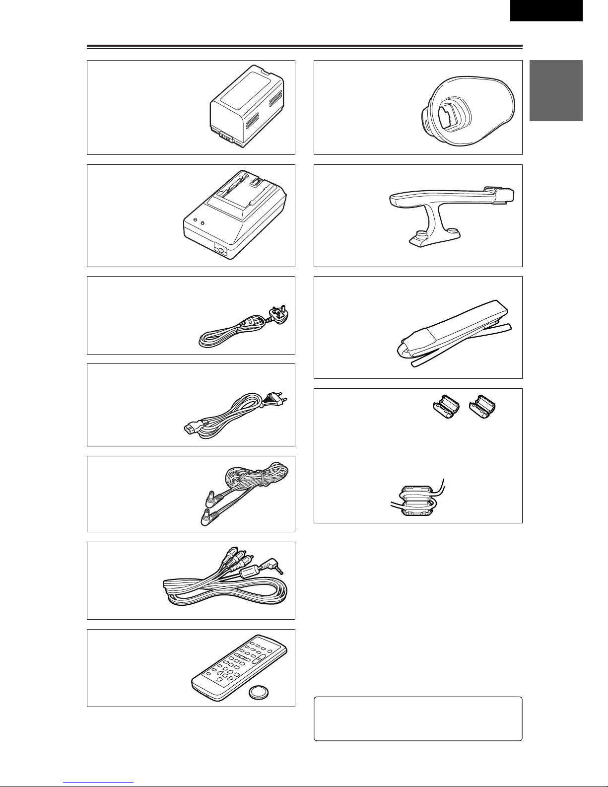
Accessories
Wireless remote control
(VFA0402)
Button battery
(CR2025)
DC cord
(K2GJ2DC00002)
AC cord
(U.K. only: K2CT3DA00001)
AC cord
(All areas except U.K.: K2CR2DA00005)
AV cable
(VYC0922)
Handle
(VYH0312)
Shoulder strap
(VFC3891)
Ferrite cores
(J0KG00000013)
Ferrite cores for DV cable:
When the DV cable is to be connected, attach
one ferrite core to one end of the cable and
the other one to the other end.
Eye-cup (large)
(VMG1370)
2: For the battery and AC adapter model
numbers, refer to the “Optional peripheral
units” section. (P86)
Battery (2)
AC adapter (2)

8 (E)
Operating precautions
Do not allow any water to get into the
camera-recorder when using it in the rain or
snow or at the beach.
O Failure to heed this caution will cause the
camera-recorder or cassette to malfunction
(and may result in irreparable damage).
Keep the camera-recorder away from
equipment (such as TV sets and video game
machines) that generate magnetic fields.
O Using the camera-recorder on top of or near
a TV set may cause distortion in the images
and/or sound due to the electromagnetic
waves that the set emits.
O The powerful magnetic fields generated by
speakers or large motors may damage your
tape recordings or distort the images.
O The electromagnetic waves emitted from a
microcomputer will adversely affect the
camera-recorder, causing the images and/or
sound to be distorted.
O If the camera-recorder is so adversely
affected by products that generate magnetic
fields that it no longer operates properly, turn
it off and remove the battery or unplug the
AC adapter from the power outlet. Then
install the battery again or re-connect the AC
adapter. After this, turn the camera-recorder
back on.
Do not use the camera-recorder near radio
transmitters or high-voltage equipment.
O Using the camera-recorder near a radio
transmitter or high-voltage equipment may
adversely affect the recorded images and/or
sound.
Do not allow any sand or dust to get into the
camera-recorder when using it at the beach
and other similar places.
O Sand and dust can damage the camera-
recorder and cassette. (Be especially careful
when inserting or removing the cassettes.)
AC adapter and battery
O If the battery has become extremely hot or
cold or if it has not been used for a long time
and has no charge, the CHARGE lamp will
blink several times and charging will start
automatically.
O If the CHARGE lamp continues to blink even
when the battery temperature is normal, it
may mean that something is wrong with the
battery or AC adapter. Consult your dealer.
O When the battery is warm, it will take longer
to charge than normal.
O When the AC adapter is used near a radio,
the sound from the radio may be distorted.
Keep the AC adapter at least a yard away
from the radio.
O Noise may be heard while the AC adapter is
being used; however, this is not a sign of
malfunctioning.
Do not drop the camera-recorder while
carrying it.
O Strong impact may damage the camera-
recorder to the extent that it will no longer
operate properly.
O When carrying the camera-recorder around,
use the hand strap, handle or shoulder strap,
and remember to handle it carefully.
Do not expose the camera-recorder to insect
sprays or volatile substances.
O Contact with insect sprays or volatile
substances may distort the shape of the
camera-recorder and/or cause its finish to
peel off.
O Do not leave the camera-recorder in contact
with rubber or PVC products for extended
periods of time.
After use, always remove the cassette and
remove the battery or unplug the AC cord
from the power outlet.
O If the cassette is left inside the camera-
recorder, the tape may become slack or
damaged.
O Leaving the battery on the camera-recorder
for an extended period may cause the battery
voltage to drop excessively, and it may not
be possible to re-use it even after charging it.

9 (E)
BEFORE USE
ENGLISH
Operating precautions (cont.)
Battery characteristics
This camera-recorder uses a rechargeable
lithium-ion battery that uses its internal chemical
reaction to generate electrical energy. This
reaction is easily influenced by the ambient
temperature and humidity, and the battery’s
effective operating time is reduced as the
temperature rises or falls. When the battery is
used in an environment where the temperature
is very low, it will not allow more than 5 minutes
of operation.
If you let the battery get very hot, its protection
function will be triggered, which will make it
unusable for some time.
Always remove the battery after use.
If it is left inside, a small amount of current will
be consumed even while the camera-recorder’s
power is off. Also, if it is left inside for an
extended period, the battery may become overdischarged and it may not be possible to re-use
it even after charging it.
To dispose of an unusable battery
O The battery has a definite service life.
In order to protect valuable natural
resources, do not throw away a battery
which you no longer need. Take it to a
store that participates in the recycling of
rechargeable batteries.
Protect the battery’s terminal area.
Keep the battery’s terminal area free of dust and
other foreign matter. If a battery has been
dropped, check whether its body or terminal
area has been bent out of shape.
Attempting to install an out-of-shape battery in
the camera-recorder or mounting it in the AC
adapter may damage the camera-recorder or
AC adapter.
Liquid crystal displays
O If the same image or characters are left
displayed on the LCD monitor or viewfinder
for an extended period, they may become
burned onto the screen. However, if the
power is kept off for several hours, the
screen will return to normal.
O The liquid crystal parts are manufactured
using high-precision technology. More than
99.99% of the pixels are effective, which
means that less than 0.01% of the pixels are
missing or permanently lit. Missing or lit
pixels are not a sign of malfunctioning and
have no effect at all on the images which are
recorded.
O Condensation may form on the liquid crystal
parts of the LCD monitor when the camerarecorder is used in places where the
temperature fluctuates significantly. If this
happens, wipe it off with a soft dry cloth.
O If the camera-recorder has become very
cold, the LCD monitor will be slightly darker
than usual immediately after the power is
turned on. Normal brightness will be restored
when the temperature inside the camerarecorder rises.
Do not point the lens or viewfinder at the
sun.
Doing so may damage the parts inside.
Protective caps for the connectors
Keep the protective caps fitted over any
connectors that are not being used.
Do not look directly at the IR light when it is
on.
When the IR light is on, light in the infrared ray
region is exposed.
As such, you could damage your eyes by
looking directly into the IR light.
Mounting the camera-recorder on a tripod
The depth of the tripod mounting hole is
5.5 mm.
When mounting this camera-recorder on a
tripod, do not force the screw beyond this
depth.
Note that if you use any screw other than
a 1/4-20UNC type you could damage the
camera-recorder.
Camera mounted on a tripod
(1/4-20UNC type of screw)

10 (E)
Storage precautions
Before storing the camera-recorder, remove
both the cassette and battery. Store all of these
items in a place with a low humidity and
relatively constant temperature.
Recommended temperature range:
15°C to 25°C
Recommended relative humidity:
40% to 60%
Camera-recorder
Wrap the camera-recorder in a soft cloth to
keep the dust off.
Battery
O The battery life is shortened in places which
are very hot or cold.
O Storing the battery in a location with oily
vapors or high dust concentrations may
corrode the terminals, cause other damage
and lead to malfunctioning.
O Keep metal objects (such as necklaces
and hairpins) away from the battery.
Short-circuiting may occur across the
terminals, causing the battery to heat up,
and you may seriously burn yourself if
you touch the battery in this state.
O The battery should be discharged for
storage. When storing it for an extended
time, we recommended that at least once a
year you charge it, use up its charge by
operating the camera-recorder, and then
store it again.
Cassette tapes
O Always rewind your tapes to the start before
storing them. If a cassette that has been
stopped part the way through is left standing
for six months or more (this timeframe differs
depending on the storage conditions), the
tape will become slack.
O Always put tapes back into their original
cases before storing them as factors such as
dust, direct sunlight (ultraviolet rays) and
humidity may damage the tapes. Dust
contains particles of hard minerals which
may damage the camera-recorder’s heads
and other parts if they get inside the
cassette.
O Fast forward and rewind your tapes once
every six months. If tapes are kept wound up
for more than a year, the expansion and
contraction caused by changes in the
temperature and humidity may distort the
tapes. Also, parts of the tape may get stuck
together.
O Do not place cassettes near equipment or
anything else with strong magnetic fields.
O The top surface of tapes is coated with
microscopically small magnetic particles
where the signals are recorded. Magnetic
necklaces, toys and other products may have
a stronger magnetic field than you might
suspect: they may be strong enough to erase
recordings and generate noise on the screen
and in the sound.

11 (E)
BEFORE USE
ENGLISH
Checking the system operations
Connecting the power cord
Getting ready
1
Connect the DC cord to the DC input socket.
After purchasing your camera-recorder, follow
the instructions for checking the system
operations to ensure that the unit is working
properly before you attempt to shoot anything.
2
Connect the other end of the DC cord and
one end of the AC cord to the AC adapter.
3
Plug the other end of the AC cord into the
power outlet.
2
2
3
1
Connect the cords properly as shown in
the figure above.
The battery cannot be charged when power
is being supplied to the camera-recorder
from the AC adapter.
AC adapter
AC cord (U.K. only)
(All areas except U.K.)
DC cord
Mini DV cassette tape

12 (E)
Checking the system operations (cont.)
Turning on the power
3
Press the part marked “PUSH” and close the
cassette holder.
When the holder is closed properly, the
cassette holder is retracted automatically.
4
Close the cassette cover after the cassette
holder has been completely retracted.
O Do not take hold of the cassette cover alone
to insert or remove tapes.
Insert and remove cassette tapes after
putting the camera-recorder down on a
stable, flat surface or hold it with both hands
to keep it stable.
O Do not forcibly push the cassette holder into
place as this may cause malfunctioning.
O Wait until the cassette holder is completely
retracted before closing the cassette cover.
3
4
O
F
F
O
N
M
O
D
E
POWER
CAMERA
VCR
Hold down the white button and turn the
POWER lever to the ON position.
The CAMERA (red) lamp lights, and the
camera-recorder switches to shooting pause
mode.
POWER lever
Inserting the cassette tape
1
Slide the OPEN/EJECT lever in the direction
of the arrow, and open the cassette cover.
When the cover is fully opened, the cassette
holder pops out automatically.
2
Insert the cassette tape.
OPEN/EJECT
1
2
Cassette cover
Cassette holder

13 (E)
BEFORE USE
ENGLISH
Checking the system operations (cont.)
1
Set the AUTO/MANUAL selector switch to
AUTO.
2
Squeeze both sides of the lens cap and
remove it.
3
Look through the viewfinder and check what
you want to shoot.
4
Shooting starts when you press the
START/STOP (red) button on the POWER
lever.
Press this button again to pause shooting
(shooting pause mode).
Shooting
O
F
F
O
N
M
O
D
E
3
4
Viewfinder
1
MANUALAUTO
2
2
In the shooting pause mode, press the
6
button.
The last two or three seconds of the scenes
you have shot are now played back.
After playback, the shooting pause mode is
restored.
SEARCH
RESET
SEARCH
DIGITAL ZOOM
REC
COUNTER RESET MODE CHK ZEBRA OIS
PHOTO SHOT
BARS
MANUALAUTO
1
Open the LCD monitor while holding down
the panel locking button.
The LCD monitor can be opened to a
maximum angle of 90°.
Forcing it past this point will damage the
camera-recorder.
Checking what you have shot
(rec check)
90°
You can conduct an image search (P35) by
holding down the 6 button in the shooting
pause mode.
Do not hold down the 6 button when
conducting a rec check.
Tape protection mode
If you leave the camera-recorder in the
shooting pause mode for 5 minutes or so, the
camera-recorder will automatically switch to
the tape protection mode and its power will
turn off.
However, when “STBY” has been selected as
the TAPE PROTECT item setting on the
OTHER FUNCTIONS screen using the
menus (P67-P70), the cylinder head will stop
instead of the power being turned off. (P79)

14 (E)
Hold down the white button and turn the
POWER lever to the OFF position.
The power is now turned off, and the CAMERA
lamp goes off.
2
Disconnect the DC cord from the DC input
socket.
O
F
F
O
N
M
O
D
E
POWER
CAMERA
VCR
Turning off the power
Disconnecting the power cord
3
Disconnect the DC cord and AC cord from
the AC adapter.
1
Disconnect the AC cord from the power
outlet.
3
3
1
2
Checking the system operations (cont.)
Removing the tape
1
Slide the OPEN/EJECT lever in the direction
of the arrow, and open the cassette cover.
When the cover is fully opened, the cassette
holder pops out automatically.
2
Take out the cassette tape.
3
Press the part marked “PUSH” and close the
cassette holder.
4
Close the cassette cover after the cassette
holder has been completely retracted.
2
OPEN/EJECT
1
3
4
O Check that the camera-recorder’s power is
on before sliding the OPEN/EJECT lever.
O Close the cassette cover if you are not
going to insert a cassette tape immediately
after removing another.
O Do not attempt to remove a tape while you
are recording. The cassette cover opens
but recording will continue, allowing outside
light and dust to adversely affect the tape.

15 (E)
BEFORE USE
ENGLISH
Adjusting the hand strap
1
Open the cover and adjust the strap length.
Adjust the hand strap to fit your hand.
2
1
2
3
1
2
Close the cover firmly.
Attaching the handle
The handle comes in handy for taking low-angle
shots or carrying the camera-recorder around.
To remove the handle, first pull the viewfinder
towards you, then loosen the coin screw.
2
Slide the handle into place.
3
Tighten the coin screw to secure the handle
firmly.
O If the coin screw is loose, the camera-
recorder may drop off.
1
Pull the viewfinder towards you.
Coin screw
Attaching the large eye-cup
When you look through the viewfinder while
wearing spectacles or when the area around the
camera-recorder is too bright, you will be able to
see the images in the viewfinder more clearly if
you attach the large eye-cup.
2
Place the large eye-cup over the viewfinder,
and fit it in the direction of the arrows.
1
Turn up the edges of the standard eye-cup
and remove it.
Eye-cup
16 (E)
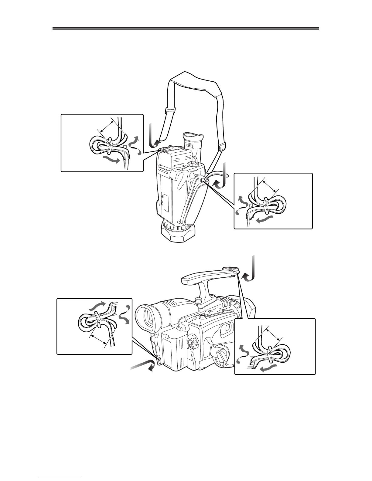
Attaching the shoulder strap
20 mm or more
20 mm or more
20 mm or more
20 mm or more
We recommended that you attach the shoulder
strap to help you avoid dropping the camerarecorder.
When the handle is not attached
When the handle is attached

17 (E)
BEFORE USE
ENGLISH
Cassette tapes
Preventing accidental erasure
To prevent erasing the recordings on a tape by
accident, set the tab on the cassette to SAVE.
REC
SAVE
$ We recommend that you use the following
mini DV cassette tapes with this camerarecorder.
AY-DVM30 (30 minutes in SP mode)
AY-DVM60 (60 minutes in SP mode)
$ Although the picture quality of material shot
in the LP mode is not bad, mosaic-like noise
may appear, limitations may apply to some of
the memory functions and/or regular
playback may not be possible when:
O a tape shot in the LP mode using this
camera-recorder is played back in another
digital video unit;
O a tape shot in the LP mode using another
digital video unit is played back in this
camera-recorder;
O a tape shot in the LP mode using this
camera-recorder is played back in another
digital video unit that does not have an LP
mode capability;
O slow or frame-feed playback is performed; or
O an image search is conducted
$ Audio dubbing cannot be performed in the LP
mode as the tracks on the tape are narrower
than the heads.
Larger flat area
Lens hood
Removing the lens hood
O Turn the lens hood counterclockwise to
remove it.
Attaching the lens hood
O Make sure that the larger flat part of the lens
hood is pointing upward, then fit it into place.
O Turn the lens hood clockwise to attach it.

18 (E)
PHONES
DV
CAM REMOTE
Description of parts
For details, refer to the respective pages.
Camera-recorder
Viewfinder (P9, P13,
P15, P25-P27, P34,
P78)
Eye-cup (P15)
Diopter adjustment lever (P25)
Battery release button
(P23)
START/STOP button
(P13, P34)
Battery connector
DC input (INPUT 7.9 V) socket
(P11, P14)
Shoulder strap eyelet (P16)
PHONES jack (P47,
P49, P54, P65, P79)
DV connector (P41, P54,
P60-P62, P75-P78)
CAM REMOTE jack
(2.5 mm diameter)
Tripod mounting hole
(P9)
Shoe (P15, P56)
Zoom buttons (P35, P75)
POWER lever (P12-P14,
P23, P34, P48, P57, P79)
Hand strap
(P15)
Shoulder strap eyelet
(P16)
Cassette holder
(P12, P14, P83)
Cassette cover
(P12, P14, P34)
USER button (P40, P51,
P57, P62, P63, P74)
POWER lamp (P12,
P14, P23, P48)
Built-in stereo microphone
(P37, P57, P58, P63, P75,
P77, P79)
START/STOP button
(P35, P75)
OPEN/EJECT lever
(P12, P14)

19 (E)
DESCRIPTION
OF PARTS
ENGLISH
Description of parts (cont.)
Camera-recorder
S-VIDEO
IN/OUT
MIC
AV
IN/OUT
XLR ADAPTER
White balance sensor (P44)
S-VIDEO IN/OUT connector
(P55)
XLR ADAPTER connector
(P56, P58)
Tally lamp (P78, P83)
Focusing ring (P35,
P41, P43, P75)
Infrared light (P36, P79)
MIC jack (P56, P58, P63, P77)
AV IN/OUT jack (P55,
P57-P59, P73, P77, P79)
Lens hood (P17)
Lens (P9)

20 (E)
Description of parts (cont.)
Camera-recorder
SEARCH
RESET
SEARCH
DIGITAL ZOOM
REC
COUNTER RESET MODE CHK ZEBRA OIS
PHOTO SHOT
BARS
MANUALAUTO
–SEARCH (6) button
(P13, P35, P48, P50)
Built-in speaker
(P49, P58, P63)
REC button
(P59, P61)
REC sub button
(P59, P61)
COUNTER button
(P53, P64)
RESET button (counter)
(P27, P31, P33, P53)
SNS button (P36, P63)
USER2 button (P40, P51, P57,
P62, P63, P74)
USER3 button
(P40, P51, P57,
P62, P63, P74)
FOCUS button (P41)
WHITE BAL button
(P44, P45)
Remote control sensor (P24)
MENU button (P26, P28, P31, P33,
P46, P47, P67, P70)
MODE CHK button (P66)
Multi dial (P26, P28, P30-P33, P42, P43,
P46, P47, P49-P52, P65, P68, P69, P75)
RESET button (P83)
Digital zoom (1) button
(P35, P48, P50, P51, P60,
P61)
SEARCH + (5) button
(P35, P48, P50)
BARS ($) button (P38,
P48, P59-P61, P63)
PHOTO SHOT (;) button
(P38, P48, P50)
OIS button (P37)
ZEBRA button (P38, P63)
AUTO/MANUAL selector
switch (P13, P34, P41,
P42, P44, P45)
Panel locking button
(P13, P25, P48)

21 (E)
DESCRIPTION
OF PARTS
ENGLISH
Description of parts (cont.)
Wireless remote control unit
Note that the following buttons are for
functions that cannot be executed on the
camera-recorder.
OTITLE OMULTI/P-IN-P
OSELECT OSTORE
OOFF/ON OPB. ZOOM
O N
1. DATE/TIME button (P49)
2. OSD button (P49)
3. COUNTER button (P53)
4. RESET button (counter)
(P27, P31, P33, P53)
5. A.DUB button (P57)
6. REC button (P59, P61)
<Playback controls>
7. PLAY button (1)
21
(P48, P50, P51, P59-P61)
8. PAUSE button (;)
21
(P48, P50, P57)
9. C/REW button (6)
21
(P35, P48, P53)
10. STILL ADV button (E, D)
(P24, P50)
11. INDEX button (:, 9)
(P52, P73)
12. STOP button ($)
21
(P24, P48, P59-P61)
13. FF/B button (5)
21
(P35, P48, P53)
21
: During playback, these buttons function in
exactly the same way as the corresponding
buttons on the camera-recorder.
<Shooting/volume controls>
14. PHOTO SHOT button
22
(P38)
15. START/STOP button
22
(P34)
16. ZOOM/VOL buttons
22
(P49)
22
: During shooting, these buttons function in
exactly the same way as the corresponding
buttons on the camera-recorder.
17. VAR.SEARCH button (P51)
18. MENU button
(P26, P28, P30, P31, P33, P46, P47, P67,
P70)
19. [V] [B], [M] buttons
(P26, P28, P30-P33, P46, P47, P51, P52,
P68, P69)
OSD
COUNTER
RESET TITLE
STILL ADV
PAUSE
STILL ADV
INDEX
SELECT
STORE
OFF/ON
P.B.DIGITAL
VAR.
SEARCH
– VOL +
PB.
ZOOM
MENU
SET
ITEM
STOP INDEX
MULTI/
P-IN-P
REC A.DUB
PLAY
C
/REW FF/
B
ZOOM
DATE/
TIME
PHOTO
SHOT
START/
STOP
114
215
3
4
6
7
9
8
10
12
11
17
5
16
13
10
11
18
19

22 (E)
Battery
Before using the battery, fully charge it in the
AC adapter.
We recommend that you keep a spare battery
with you whenever you use the battery to run
the camera-recorder.
Charging time Continuous recording time
1
Align the battery with the “” marking on
the AC adapter, place it flat, and slide it in
the direction shown below.
O Before doing this, disconnect the DC cord
from the AC adapter as the battery cannot
be charged if it is connected.
2
Connect the AC cord to the power outlet.
O The POWER lamp and CHARGE lamp on
the AC adapter light, and charging begins.
O If the CHARGE lamp does not light when
the battery is placed in the AC adapter,
remove the battery and place it in the
adapter once again.
3
When the battery has been charged, the
CHARGE lamp on the AC adapter goes off.
4
Slide the battery, and remove it.
POWER
CHARGE
Approx. 120 minutes Approx. 120 (or 100) minutes
O Times given above are approximations only.
The figure in parentheses is the time that applies when the
LCD monitor is used.
O The times given above apply when the ambient operating
temperature is 20°C and ambient humidity is 60%.
Charging may take longer at other temperatures and
humidity levels.
OKeep metal objects (such as necklaces and hairpins)
away from the battery. Short-circuiting may occur
across the terminals, causing the battery to heat up,
and you may seriously burn yourself if you touch the
battery in this state.
OThe battery becomes hot while it is being used or
charged.
Similarly, the camera-recorder body becomes hot during
use.
OIf recording and stopping are done unnecessarily and
repeatedly, the recording time will be less than the figure
given in the table above.
OThe battery should be discharged for storage.
When storing it for an extended time, we recommend that
at least once a year you charge it, use up its charge by
operating the camera-recorder, and then store it again.
OIf the battery is extremely hot or cold, the CHARGE lamp
will blink several times before charging starts.
Similarly, if the battery has not been used for an extended
period of time and has no charge, the CHARGE lamp will
blink several times before charging starts.
OIf the CHARGE lamp continues to blink even when the
battery temperature is normal, it may mean that
something is wrong with the battery or AC adapter.
Contact your dealer.
OIt takes longer to charge a battery that is warm.
OWhen the AC adapter is used near a radio, the sound
from the radio may be distorted. Keep the AC adapter at
least a yard away from the radio.
ONoise may be heard from an AC adapter while it is being
used. This is not a sign of malfunctioning.
OThe battery cannot be charged when power is being
supplied to the camera-recorder from the AC adapter.
Charging and recording times of accessory
battery
Charging

23 (E)
PREPARATION
ENGLISH
1
Raise the viewfinder.
2
Press the battery straight against the
camera-recorder body and slide it down until
it clicks into place.
3
Return the viewfinder to its original position.
O Turn the POWER lever to the OFF position,
check that the POWER lamp
(CAMERA/VCR) has gone off, and then
remove the battery.
O Support the battery with your hand so that it
does not drop off.
Battery (cont.)
Mounting
To remove the battery, hold down the battery
release button and slide it up.
Removing

24 (E)
Remote control unit
Setting the remote control unitInstalling the battery
When two camera-recorders are used
simultaneously, either [VCR1] or [VCR2] can be
set for this camera-recorder and the wireless
remote control unit so that the remote control
unit will not be used to operate the wrong
camera-recorder by mistake.
O The remote control sensor used for this is
located at the lower side of the lens on the
camera recorder. Point the wireless remote
control unit towards the sensor when
operating the camera-recorder with it.
Setting procedure
O Wireless remote control unit
Press the STOP ($) and STILL ADV (D)
buttons at the same time to set the remote
control unit for use with VCR1. Alternatively,
press the STOP ($) and STILL ADV (E)
buttons at the same time to set the remote
control unit for use with VCR2.
When the battery in the remote control unit is
replaced, the remote control unit is set for
use with VCR1.
O Camera-recorder
Use the menus (P67-P70) to set the
REMOTE item on the OTHER FUNCTIONS
screen. (P78)
If different settings are used for the camerarecorder and remote control unit, “REMOTE” will
light up in red on the viewfinder and LCD
monitor.
1
Pull out the battery holder while pressing the
knob in the direction of arrow 1.
2
Insert the battery with the “+” marked side
facing up.
3
Return the holder to its original position.
O When the battery (CR2025) has run out,
replace it with a new one. (The service life of
the battery is about one year, although this
depends on how often the remote control is
used.) If the remote control unit fails to work
even when it is operated near the camerarecorder’s remote control sensor, it means
that the battery has run out.
O Keep the battery out of the reach of small
children.
OSD
COUNTER
RESET TITLE
STILL ADV
PAUSE
STILL ADV
INDEX
SELECT
STORE
OFF/ON
P.B.DIGITAL
VAR.
SEARCH
– VOL +
PB.
ZOOM
MENU
SET
ITEM
STOP INDEX
MULTI/
P-IN-P
REC A.DUB
PLAY
C
/REW FF/
B
ZOOM
DATE/
TIME
PHOTO
SHOT
START/
STOP
VCR 2 VCR 1

25 (E)
PREPARATION
ENGLISH
Viewfinder
1
Set the POWER lever to the ON position,
and check that images appear in the
viewfinder.
O Keep the LCD monitor closed.
2
Adjust the viewfinder’s angle so that the
screen is positioned where it is easiest to
see.
3
Adjust the diopter adjustment lever so that
the characters on the viewfinder screen are
seen most clearly.
Do not point the viewfinder at the sun.
Doing so may damage the parts inside.
This camera-recorder offers a choice of
viewfinders: a viewfinder with a small LCD
screen and one with a 3.5-inch LCD monitor.
Use the viewfinder that best suits the application
and shooting conditions.
O The brightness and hue may differ between
the images appearing on the viewfinder and
LCD monitor and those displayed on a TV
monitor.
To see how the final images will appear,
check them on a TV monitor.
Using the viewfinder
Diopter adjustment
lever
Viewfinder
Using the LCD monitor
1
Set the POWER lever to the ON position.
2
Open the LCD monitor while holding down
the panel locking button.
The LCD monitor can be opened to a
maximum angle of 90°.
Forcing it past this point will damage the
camera-recorder.
3
Position the LCD monitor where it is easiest
to see.
O The monitor can be rotated by 180
degrees toward the lens and 90 degrees
toward you.
Forcing the monitor beyond these
angles or attempting to close the
monitor while it has been rotated by 90
degrees will damage the camerarecorder.
180° 90°
90°
O
F
F
O
N
M
O
D
E
O When closing the LCD monitor, ensure that
it is closed securely.
O When the LCD monitor is rotated toward
the lens (for self-portrait shooting), the
viewfinder and LCD monitor will light up at
the same time.

26 (E)
When the [M] button on the remote control unit is used to make adjustments, the level meter
reading starts changing in the opposite direction once it has reached the maximum (or minimum)
position.
Viewfinder (cont.)
1
Use the menus (P67-P70) to select “YES” as
the LCD/EVF SET item setting on the
DISPLAY SETUP screen.
Adjusting the screen display
2
The LCD/EVF SET screen with “LCD
BRIGHTNESS” selected appears. Turn the
multi dial to adjust the brightness of the LCD
monitor screen.
DISPLAY SETUPDISPLAY SETUP
LCD/EVF SETLCD/EVF SET –––––––– YES YES
SELF SHOOT NORMAL
EVF MODE AUTO
EVF COLOUR ON
PUSH MENU TO RETURNPUSH MENU TO RETURN
PB.
ZOOM
MENU
SET
ITEM
SHUTTER/IRIS
VOL/JOG
PUSH
LCD/EVF SETLCD/EVF SET
LCD BRIGHTNESS LCD BRIGHTNESS
[–]
? ? ? ?
––––[+]
LCD COLOUR LEVEL
[–]
? ? ? ?
––––[+]
EVF BRIGHTNESS
[–]
? ? ? ?
––––[+]
PUSH MENU TO RETURNPUSH MENU TO RETURN
PB.
ZOOM
MENU
SET
ITEM
SHUTTER/IRIS
VOL/JOG
PUSH
3
Upon completion of the settings, press the
multi dial to select “LCD COLOUR LEVEL.”
LCD/EVF SETLCD/EVF SET
LCD BRIGHTNESS
[–]
? ? ? ?
––––[+]
LCD COLOUR LEVEL LCD COLOUR LEVEL
[–]
? ? ? ?
––––[+]
EVF BRIGHTNESS
[–]
? ? ? ?
––––[+]
PUSH MENU TO RETURNPUSH MENU TO RETURN
PB.
ZOOM
MENU
SET
ITEM
SHUTTER/IRIS
VOL/JOG
PUSH
6
Turn the multi dial to adjust the brightness of
the viewfinder screen.
LCD/EVF SETLCD/EVF SET
LCD BRIGHTNESS
[–]
? ? ? ?
––––[+]
LCD COLOUR LEVEL
[–]
? ? ? ?
––––[+]
EVF BRIGHTNESS EVF BRIGHTNESS
[–]
? ? ? ?
––––[+]
PUSH MENU TO RETURNPUSH MENU TO RETURN
PB.
ZOOM
MENU
SET
ITEM
SHUTTER/IRIS
VOL/JOG
PUSH
5
Upon completion of the settings, press the
multi dial to select “EVF BRIGHTNESS.”
LCD/EVF SETLCD/EVF SET
LCD BRIGHTNESS
[–]
? ? ? ?
––––[+]
LCD COLOUR LEVEL
[–]
? ? ? ?
––––[+]
EVF BRIGHTNESS EVF BRIGHTNESS
[–]
? ? ? ?
––––[+]
PUSH MENU TO RETURNPUSH MENU TO RETURN
PB.
ZOOM
MENU
SET
ITEM
SHUTTER/IRIS
VOL/JOG
PUSH
4
Turn the multi dial to adjust the colour level
of the LCD monitor screen.
LCD/EVF SETLCD/EVF SET
LCD BRIGHTNESS
[–]
? ? ? ?
––––[+]
LCD COLOUR LEVEL LCD COLOUR LEVEL
[–]
? ? ? ?
––––[+]
EVF BRIGHTNESS
[–]
? ? ? ?
––––[+]
PUSH MENU TO RETURNPUSH MENU TO RETURN
PB.
ZOOM
MENU
SET
ITEM
SHUTTER/IRIS
VOL/JOG
PUSH
7
Press the MENU button three times to exit
the menu mode.
SELECT
STORE
OFF/ON
P.B.DIGITAL
VAR.
SEARCH
PB.
ZOOM
MENU
SET
ITEM
MENU

27 (E)
PREPARATION
ENGLISH
Viewfinder (cont.)
Adjusting the screen display
O If the RESET button (counter) is pressed
when it is possible to change the settings
by selecting the LCD/EVF SET item, the
values set for those items (LCD
BRIGHTNESS and COLOUR LEVEL, and
EVF BRIGHTNESS) can be returned to the
factory settings.
O When “ON” is selected as the setting for the
EVF MODE item on the DISPLAY SETUP
screen, the images will always be displayed
on the viewfinder even if the LCD monitor is
open. (P78)
O Using the EVF COLOUR item on the
DISPLAY SETUP screen, either colour or
black and white can be selected for
displaying the viewfinder images. (P78)
No matter whether colour or black and
white is selected, the images will have the
same resolution.
O When you press the USER button to which
the EVF DTL function has been allocated,
the contours of the images in the viewfinder
and LCD monitor are emphasized, making
it easier to bring the subject into focus.
(P74)
Note that the contours of the images will
still be emphasized to make focusing easier
even if “ON” has been selected as the EVF
DETAIL item setting on the DISPLAY
SETUP screen. (P78)
OSD
COUNTER
RESET TITLE
MULTI/
P-IN-P
REC A.DUB
ZOOM
DATE/
TIME
PHOTO
SHOT
START/
STOP
SEARCH
RESET
SEARCH
DIGITAL ZOOM
REC
COUNTER RESET MODE CHK ZEBRA OIS
PHOTO SHOT
BARS
MANUALAUTO
 Loading...