

Page 1
Operating Instructions
取扱説明書
Color Camera
カラーカメラ
Model No.
Before operating this product, please read the instructions carefully
and save this manual for future use.
AG-CK10P
ENGLISH
日本語
このたびは、パナソニック製品をお買い上げいただき、まことにありがとう
ございます。
●取扱説明書をよくお読みのうえ、正しく安全にお使いください。
●ご使用前に「安全上のご注意」を必ずお読みください。
●保証書は「お買い上げ日・販売店名」などの記入を確かめ、取扱説明書と
ともに大切に保管してください。
S0806K4088 -M
Printed in Japan
VQT1A21-4
Page 2
Read this first!
WARNING:
• TO REDUCE THE RISK OF FIRE OR SHOCK HAZARD, DO NOT
EXPOSE THIS EQUIPMENT TO RAIN OR MOISTURE.
• TO REDUCE THE RISK OF FIRE OR SHOCK HAZARD, KEEP THIS
EQUIPMENT AWAY FROM ALL LIQUIDS. USE AND STORE ONLY
IN LOCATIONS WHICH ARE NOT EXPOSED TO THE RISK OF
DRIPPING OR SPLASHING LIQUIDS, AND DO NOT PLACE ANY
LIQUID CONTAINERS ON TOP OF THE EQUIPMENT.
CAUTION:
TO REDUCE THE RISK OF FIRE OR SHOCK HAZARD AND
ANNOYING INTERFERENCE, USE THE RECOMMENDED
ACCESSORIES ONLY.
indicates safety information.
E-1
Page 3
Read this first!
FCC Note:
This equipment has been tested and found to comply with the limits
for a class A digital device, pursuant to Part 15 of the FCC Rules.
These limits are designed to provide reasonable protection against
harmful interference when the equipment is operated in a commercial
environment. This equipment generates, uses, and can radiate radio
frequency energy, and if not installed and used in accordance with
the instruction manual, may cause harmful interference to radio
communications. Operation of this equipment in a residential area
is likely to cause harmful interference in which case the user will be
required to correct the interference at his own expense.
Warning: To assure continued FCC emission limit compliance, the user
must only use shielded interface cables when connecting to external
units. Also, any unauthorized changes or modifications to this equipment
could void the user’s authority to operate it.
(continued)
• This camera is designed for use and installation in a vehicle.
• The installation of this equipment must only be performed by a
professional installer.
• The rating plate is on the underside of this equipment.
indicates safety information.
ENGLISH
E-2
Page 4

IMPORTANT SAFETY INSTRUCTIONS
(1) Read these instructions.
(2) Keep these instructions.
(3) Heed all warnings.
(4) Follow all instructions.
(5) Do not use this equipment near water.
(6) Clean only with a dry cloth.
(7) Do not block any ventilation openings. Install in accordance with the
manufacturer’s instructions.
(8) Do not install near any heat sources such as radiators, heat registers, stoves,
or any other equipment (including amplifiers) that produce heat.
(9) Only use attachments/accessories specified by the manufacturer, and as
outlined in this manual.
(10) Refer all servicing requests to qualified service personnel. Servicing is
required when the equipment has been damaged in any way, such as
damage to the power supply cord or plug, liquid being spilled on or objects
have fallen into the equipment, the equipment has been exposed to rain or
moisture and does not operate normally, or has been dropped.
E-3
Page 5

Contents
Read this first! ..................................................................................... E-1
IMPORTANT SAFETY INSTRUCTIONS .............................................. E-3
Included accessories .......................................................................... E-4
Control reference guide ...................................................................... E-5
Connector signals ............................................................................... E-6
Connections ......................................................................................... E-7
Camera operation ................................................................................ E-8
Troubleshooting .................................................................................. E-9
Specifications .................................................................................... E-10
Worldwide Product Warranties ........................................................ E-11
Included accessories
Wide conversion lens (installed on the Color Camera) ..........................................1
Camera cable (divided into 2 pieces) ..................................................................... 1
Camera mount
∗ Contact your supplier when installing this unit using a camera mount.
This Color Camera is designed for use only with the AG-CPD15P Memory Card Video
Recorder and AG-CPD10CRUP Memory Card Video Recording System. Do not
attempt to use it with any models other than the AG-CPD15P or AG-CPD10CRUP.
Caution regarding laser beams
The CCD may be damaged if it is subjected to light from a laser beam.
When using the camera-recorder in locations where laser irradiation equipment is
used, be careful not to allow the laser beam to shine directly on the lens.
∗
......................................................................................................1
E-4
ENGLISH
Page 6
Control reference guide
Front
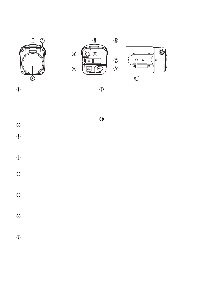
REC lamp
You can set this to light or blink during
recording, or to stay unlit all the time.
For details on configuring settings,
refer to the Operating Instructions of
the Memory Card Video Recorder, or
contact your supplier.
Sunshade
Protects the lens from direct sunlight.
Wide conversion lens
The wide conversion lens enables a
wider viewing angle when recording
video.
Backlight compensationbutton
Controls the backlight compensation
function. (see page E-8)
Light button
Switches the camera operation button
illumination between lit and unlit.
(see page E-8)
Camera cable connector
Use the supplied camera cable to
connect the camera to the Memory
Card Video Recorder.
Zoom buttons
Control the zoom function. The [W ]
button serves to zoom out and the
[T] button to zoom in.
AUTO ZOOM button
Pressing this button causes the
camera to automatically zoom in,
pause for a certain period, and
zoom out. (see page E-8)
TopRear
A
B
REC button
Pressing this button causes the
Memory Card Video Recorder to
start recording. To stop an ongoing
recording, keep pressing the [REC]
button for about 2 seconds.
Camera mount holes
The supplied camera mount can be
attached here.
When the wide conversion lens is
mounted, use the front hole (A).
When the wide conversion lens is
removed, use the rear hole (B).
Contact your supplier when
installing the camera.
Notes:
• Use only the wide conversion lens
that was mounted on the camera
when delivered.
Use only the specified camera mount
•
positions to install the camera.
E-5
Page 7
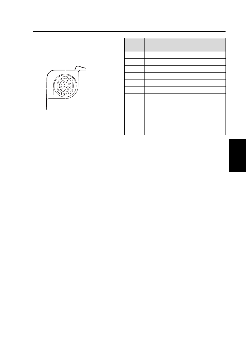
Connector signals
Camera cable connector
(female)
10
9
12
5
1
11
Pin
number
1 GND (SHIELD)
2 REC_LED_L
3 RxD
4 TxD
5 GND (TxD/RxD)
6 GND (V_OUT)
7 DC_IN
8 GND (DC_IN)
9 REC_L
10 AUTO_ZOOM_L
11 BL_L
12 V_OUT
Signal
ENGLISH
E-6
Page 8
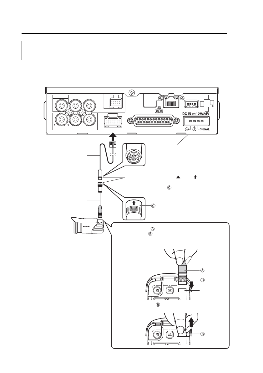
Connections
• Because of the fire hazard, contact your supplier for assistance with installation
and connection.
Refer to the connector illustration on the previous page and the Operating
Instructions of the Memory Card Video Recorder to ensure that you make
connections correctly.
VIDEO OUT
AUDIO OUT
IN CAR MIC
CONTROL PANEL
GPS-ANT.
(OPTION)
USB
AUDIO IN
7.5 m (24.6 feet)
camera cable (provided)
0.5 m (1.64 feet)
camera cable (provided)
Color Camera
CAMERA 2
CAMERA 1
To connect
To disconnect
GPIO/SERIAL
Memory Card Video Recorder
To connect
To disconnect :Slide in the reverse
:
Align the “ ” and “ ”
:
marks to connect.
direction of the arrow to
disconnect the connector.
Grasp on the 0.5 m (1.64 feet) camera cable, and
align with the camera cable connector. Rotate the
plug to find the position where the guides match,
and insert it in the direction of the arrow.
:
Grasp and pull the plug out in the direction
of the arrow.
(separately sold)
Camera cable
connector
E-7
Page 9

Camera operation
Zoom function
The camera has the capability for optical zoom (x22) and digital zoom (x10).
The zoom function is controlled with the [W] button and the [T] button.
The maximum zoom factor is x220.
Note:
When zooming in on a subject from the wide end, zooming automatically
pauses at the x22 limit of the optical zoom. To zoom beyond this limit with
the digital zoom, release the zoom button momentarily and press it again,
holding it down until the desired zoom factor is reached.
Auto zoom function
When you press the [AUTO ZOOM] button, the camera will automatically zoom
in, pause for a certain period, and zoom out.
Refer to the Operating Instructions of the Remote Control Panel for the setup
procedures for zooming and stop time.
Backlight compensation function
When you press the Backlight compensation button, the backlight compensation
function is activated. Each push of the button toggles the function between ON
and OFF.
Light button
Pressing this button activates the camera operation button illumination.
Press this button to switch between lit and unlit.
ENGLISH
E-8
Page 10

Troubleshooting
Starting up
Symptom Confirmation Details
Power does not come on. • Is the camera cable connected correctly?
Unusual sound is heard. • Some operating sounds may be evident when
During operating
Symptom Confirmation Details
Video is distorted or not
recorded.
Recorded video is in black
and white.
Focusing does not work. •
Refer to the connections on page E-7.
powering on, switching IR modes and zooming.
Sounds in such cases do not necessarily
indicate a problem.
(Refer to the Operating Instructions of the Remote
Control Panel.)
• Are camera and video monitoring equipment
connected properly?
• Are both the video input connector selection
and the input selection made with the Remote
Control Panel the same?
• Are the video output settings correct for the
connected equipment? Connect a monitor to
the [VIDEO OUT] connector on the rear panel
of the Memory Card Video Recorder and check
the picture.
• The IR function was enabled, which results in a
B/W picture.
Are you attempting to record video of scenes that
are hard to focus? In the following conditions,
focusing may be difficult.
examples are listed below:
• The field of view includes both distant and
near objects.
•
The camera is shooting through dirty window glass.
• Ambient lighting is low.
•
There are bright and reflective surfaces around
the object.
•
The camera is shooting a rapidly moving object.
• The object has little contrast.
•
A close-by object is being shot at high zoom ratio.
E-9
• The camera can also be focused manually. For
details, refer to the Operating Instructions of the
Remote Control Panel.
Page 11

Specifications
Power requirements: 12 V DC
Input current: 0.52 A
indicates a safety related item.
Operating temperature:
0 °C to 45 °C (32 °F to 113 °F)
Operating humidity:
10 % to 80 % (no condensation)
Weight
520 g (1.15 lb)
Dimensions (W x H x D)
72 mm x 82 mm x 166 mm
(2-27/32 inches x 3-7/32 inches
x 6-17/32 inches)
(Including sunshade)
Connectors:
Power / control signal input and
output / video output (12-pin round
connector)
Image sensor
1/4 inch CCD
380,000 pixels (effective area)
Lens
Focal length:
(optical zoom x22, digital zoom x10)
(without wide conversion lens)
f = 3.79 mm - 83.4 mm
:
(with wide conversion lens):
f = 2.65 mm - 58.4 mm
Maximum aperture ratio:
F1.6 (WIDE) - F3.0 (TELE)
Field angle:
(without wide conversion lens)
(Horizontal) 2.6 ° (TELE) - 52.3 ° (WIDE)
:
(with wide conversion lens):
(Horizontal) 3.5 ° (TELE) - 68.4 ° (WIDE)
Sensitivity
0.7 lx (Color, AGC HIGH)
0.04 lx (B/W, AGC HIGH)
Weight and dimensions are approximate.
Specifications are subject to change
without notice.
ENGLISH
E-10
Page 12

Panasonic Computer Solutions Company
Worldwide Product Warranties
Section 1: Limited Warranty - Hardware
Panasonic Computer Solutions Company (referred to as
"Panasonic") will repair the products listed below with new or
rebuilt parts, free of charge in the U.S.A. or other Panasonic
approved location for the period specified below from the date
of original purchase in the event of a defect in materials or
workmanship. These warranties are extended solely to the
original purchaser. A purchase receipt or other proof of date of
original purchase will be required before warranty performance
is rendered.
• Laptop Computers – 3 Years
• PDRC - LCD and Keyboard Assemblies – 3 Years
• MDWD – Mobile Computer and Wireless Display Assemblies
- 3 Years
• Hand-held Computers (P1/P2) – 1 Year
• Arbitrator Video Camera – 1 Year
• Arbitrator Recorder Unit – 1 Year
• Arbitrator Remote Control Panel – 1 Year
• Arbitrator Wireless Receiver Unit – 1 Year
• Arbitrator P2 Card(s) (All Sizes) – 1 Year
• Arbitrator Wireless Microphone(s) / Transmitter – 90 Days
• Arbitrator System Component Interconnect Cables – 90 Days
Main Battery
The battery supplied with the product is covered under the
warranty for one (1) year from date of purchase, except as
excluded in Section 3. Batteries purchased separately are
covered under the warranty for one (1) year from the date of
purchase. A battery furnished under the warranty is covered for
the remaining period of the one year warranty on the original or
purchased battery.
Options and Accessories
The below listed Panasonic brand or supplied options and
accessories are covered under this limited warranty for the
period specified from the date of purchase or as specifically
stated:
• AC Adapter / Power Cord – 3 Years
• Memory Card (Panasonic Brand) – 3 Years
• Car Mount Docking Station PCB or Complete Vehicle
Docking Station – 3 Years
• Port Replicator / I-O Box – 3 Years
• Antenna Pass-through Cable – 3 Years
• Backlit or Full-sized keyboard - 3 Years or assumes warranty
of the unit in which it is installed
• Integrated Panasonic supplied options and kits including, but
not limited to Wireless Modems, Media Bay Drives (Floppy,
CD, DVD, Combo), GPS, Bluetooth, Smartcard Reader, and
Fingerprint readers – 3 Years or assumes warranty period of
the unit in which it is installed provided the integration was
performed by Panasonic or an Authorized Options Integrator
• Hard Drive (separately purchased) – 1 Year
• External USB Drives (CD / DVD / Floppy / Hard Drive) –
1 Year
• Optional Battery – 1 Year
• Battery Charger – 1 Year
• Standard or Digitizer Stylus Pens – 90 Days (physical
damage excluded)
Section 2 - Limited Warranty - Software
Panasonic Computer Solutions Company (referred to as
"Panasonic") warrants to you only that the disk(s) or other
media on which the Programs are furnished will be free from
defects in material and workmanship under normal use for a
period of sixty (60) days from the date of delivery thereof to
you, as evidenced by your purchase receipt.
E-11
This is the only warranty Panasonic makes to you. Panasonic
does not warrant that the functions contained in the Programs
will meet your requirements or that the operation of the
Programs will be uninterrupted or error free. Panasonic shall
have no obligation for any defects in the disk(s) or other
media on which the Programs are furnished resulting from
your storage thereof, or for defects that have been caused by
operation of the disk(s) or other media.
Panasonic’s entire liability and your exclusive remedy under
this warranty shall be limited to the replacement, in the
United States or other Panasonic designated location, of any
defective disk or other media which is returned to Panasonic's
Authorized Service Center, together with a copy of the
purchase receipt, within the aforesaid warranty period. The
customer is responsible for ensuring that all data is backed up
and made secure during normal use and before sending a unit
for service.
Section 3 - Limited Warranty Exclusions
Specifically excluded from the warranty are:
• All consumable items; such as screen protection films, logo
badges, labels, cleaning cloths, carry cases, manuals, cables,
straps, belts, holsters, tethers, and harnesses and any other
options and accessories not listed above or covered under a
separate warranty
• Failures related to the product operating system, hard
drive image, software setup, software program, virus, other
program(s) or file(s) on the hard drive or in any computer
memory location
• Failures due to BIOS settings or changes, as well as any
cosmetic or physical damage to the unit
• Any unit or device with a missing or altered model number or
serial number label
• Damage which occurs in shipment
• Failures which are caused by products not supplied by
Panasonic
• Failures which result from alteration, accident, misuse,
introduction of liquid or other foreign matter into the unit,
abuse, neglect, installation, maladjustment of consumer
controls, improper maintenance or modification, use not in
accordance with product use instructions
• Failures due to service by anyone other than a Panasonic
Authorized Service Provider
• Failures caused by improper integration by any company
other than Panasonic Configuration and Integration Centers
• Damage, failure, or loss due to the unit being stolen, lost,
misplaced, or used by anyone other than the original purchaser
• Damage that is attributable to acts of God
This warranty only covers failures due to defects in materials
or workmanship which occur during normal use.
Other Limits and Exclusions: There are no other express
warranties except as listed above.
PANASONIC SHALL NOT BE LIABLE FOR LOSS OF DATA
OR OTHER INCIDENTAL OR CONSEQUENTIAL DAMAGES
RESULTING FROM THE USE OF THIS PRODUCT, OR
ARISING OUT OF ANY BREACH OF THIS WARRANTY.
ALL EXPRESS AND IMPLIED WARRANTIES, INCLUDING
THE WARRANTIES OF MERCHANTABILITY AND FITNESS
FOR A PARTICULAR PURPOSE ARE LIMITED TO THE
APPLICABLE WARRANTY PERIOD SET FORTH ABOVE.
Some states do not allow the exclusion or limitation of
incidental or consequential damages, or limitations on how
long an implied warranty lasts, so the above limitations or
exclusions may not apply to you.
This limited warranty gives you specific legal rights, and you
may also have other rights which vary from state to state.
For technical support or to arrange for service on your
Panasonic computer product, call our toll-free 24 hour hotline
at 1-800-LAPTOP5.
Page 13

もくじ
安全上のご注意・・・・・・・・・・・・・・・・・・・・・・・・・・・ J-2
付属品・・・・・・・・・・・・・・・・・・・・・・・・・・・・・・・ J-4
各部の名称と機能・・・・・・・・・・・・・・・・・・・・・・・・・・ J-5
コネクターの信号・・・・・・・・・・・・・・・・・・・・・・・・・・ J-6
接続・・・・・・・・・・・・・・・・・・・・・・・・・・・・・・・・ J-7
カメラの操作・・・・・・・・・・・・・・・・・・・・・・・・・・・・ J-8
修理を依頼される前に・・・・・・・・・・・・・・・・・・・・・・・・ J-9
保証とアフターサービス・・・・・・・・・・・・・・・・・・・・・・・J-10
定格・・・・・・・・・・・・・・・・・・・・・・・・・・・・・・・・J-11
ENGLISH
日本語
本機は、メモリーカードレコーダー(AG-CPD15)専用のカラーカメラです。
AG-CPD15以外の機器には使用できません。
レーザー光線についてのご注意
レーザー光線がCCDに照射されると、CCDを破損するおそれがあります。
レーザー照射機器が使用されている環境で撮影する場合は、レンズにレーザー
光線が照射されないよう、十分ご注意ください。
J-1
J-1
Page 14
安全上のご注意
お使いになる人や他の人への危害、財産への損害を未然に防止するため、
必ずお守りいただくことを、次のように説明しています。
■表示内容を無視して誤った使い方をしたときに生じる危害や損害の程
度を、次の表示で区分し、説明しています。
必ずお守りください
警告
注意
■お守りいただく内容の種類を、次の絵表示で区分し、説明しています。
(下記は絵表示の一例です)
このような絵表示は、してはいけない「禁止」内容です。
この絵表示は、必ず実行していただく「強制」内容です。
この表示の欄は、「死亡または重傷などを負う可能
性が想定される」内容です。
この表示の欄は、「傷害を負う可能性または物的損
害のみが発生する可能性が想定される」内容です。
警告
水場で使用しない
火災の原因になり
ます。
水場
使用禁止
・雨や水滴などがかからない場
所でご使用ください。
カメラケーブルが破損
するようなことはしない
(傷つけたり、加工した
り、熱器具に近づけたり、
無理に曲げたり、ねじっ
たり、引っ張ったり、重
いものを載せたり、束ね
たりしない)
J-2
傷んだまま使用す
ると、火災・ショー
トの原因になります。
・ケーブルの修理は、お買い上
げの販売店にご相談ください。
Page 15

安全上のご注意
(つづき)
分解や改造をしない
火災の原因になりま
す。また、使用機器
を損傷することがあ
ります。
・
内部の点検や修理などは、お買い
上げの販売店にご相談ください。
内部に金属物を入れたり、
水などの液体をかけたり
ぬらしたりしない
ショートや発熱によ
り、火災・故障の原
因になります。
・機器の近くに水などの液体の
入った容器や金属物を置かな
いでください。
乗り物を運転しながら
使わない
事故の誘発につなが
ります。
指定外の製品と接続し
ない
火災や、事故を起こ
す原因になります。
故障や異常な状態のまま
使用しない
万一、故障(映像が
映らない、音が出な
いなど)や異常(異
物が入った、水がか
かった、煙が出る、
異音・異臭がするな
ど)が起きた場合は、
ただちに使用を中止
し、必ずお買い上げ
の販売店にご相談く
ださい。
そのまま使用を続け
ると、火災や事故の
原因になります。
日本語
J-3
Page 16

安全上のご注意
(つづき)
注意
配線・取り付け/取り外
しは、専門技術者に依頼
する
配線・取り付け/取
り外しには、専門技
術と経験が必要です。
安全のため、必ずお
買い上げの販売店に
ご依頼ください。
落下したり動かないよう
に、確実に固定する
確実に固定しない
と、事故の原因に
なります。
付属品
本機の上に重いものを置い
たり、つり下げたりしない
・落下したり倒れた
りして壊れ、けが
の原因になります。
・重量で外装ケース
が変形し、内部部
品が破損すると、
火災・故障の原因
になります。
ワイドコンバージョンレンズ(カラーカメラに搭載済).......... 1
カメラケーブル(長短ケーブル2本で構成)............... 1
カメラマウント∗ ........................... 1
∗
カメラマウントを使用して本機を取り付ける際は、お買い上げの販売店にご相
談ください。
J-4
Page 17

各部の名称と機能
フロント
リア トップ
RECランプ
設定により、記録中の点灯および点滅、
または常時消灯にすることができます。
設定方法は、メモリーカードレコー
ダーの取扱説明書を参照するか、お買
い上げの販売店にご相談ください。
サンシェード
レンズを直射日光から保護します。
ワイドコンバージョンレンズ
より広角な映像をとらえるためのレ
ンズです。
逆光補正ボタン
逆光補正を行います。(J-8ページ参照)
照明ボタン
カメラの操作ボタンが点灯します。
(J-8ページ参照)
カメラケーブル端子
付属のカメラケーブルを使用してメモ
リーカードレコーダーと接続します。
ズームボタン
ズーム動作を行います。ズームアウ
ト(Wボタン)とズームイン(Tボ
タン)の動作を行います。
AUTOZOOMボタン
ズームイン、一定時間停止、ズーム
アウトの動作を自動的に行います。
(J-8ページ参照)
A
B
RECボタン
メモリーカードレコーダーが記録を
開始します。記録中に約2秒間押し
続けると、記録は停止します。
カメラマウント取り付け穴
付属のカメラマウントを取り付けま
す。ワイドコンバージョンレンズが
付いた状態では、前側(A)の取り
付け穴に取り付けてください。ワイ
ドコンバージョンレンズを外した状
態では、後ろ側(B)に取り付けて
ください。取り付けの際は、お買い
上げの販売店にご相談ください。
お願い:
・ワイドコンバージョンレンズは、必
ず工場出荷時に取り付けられていた
ものをご使用ください。
・
カメラマウントの取り付け位置は、必
ず指定の位置に取り付けてください。
日本語
J-5
Page 18

コネクターの信号
カメラケーブル端子
(メス型)
10
9
12
5
ピンNo 信号内容
1 GND(SHIELD)
2 RECLEDL
3 RxD
4 TxD
1
11
5 GND(TxD/RxD)
6 GND(VOUT)
7 DCIN
8 GND(DCIN)
9 RECL
10 AUTOZOOML
11 BLL
12 VOUT
J-6
Page 19

接続
・火災の恐れがあるため、取り付けや接続は、お買い上げの販売店にご相談くだ
さい。
前ページのコネクター信号の図とメモリーカードレコーダーの取扱説明書をよく
お読みのうえ、正しく接続してください。
VIDEO OUT
AUDIO OUT
IN CAR MIC
CONTROL PANEL
GPS-ANT.
(OPTION)
USB
AUDIO IN
7.5mカメラ
ケーブル
(付属)
0.5mカメラ
ケーブル
(付属)
CAMERA 2
本機
CAMERA 1
取り付け 時 :0.5mカメラケーブルの○を持ち、○とカメ
取り外し時: ○を持ち、 方向にまっすぐ引いて取り外す
GPIO/SERIAL
メモリーカードレコーダー(別売)
取り付け 時 :
取り外し時:
▲と を
合わ せ るように 接 続する
を の向きと反対方向に
スライドさせて 取り外す
ラケーブル 端子を合わせて、左右に軽く回
転させ、ガイドが合った位置で 方向にまっ
すぐ差し込 む
カメラ
ケーブル端子
日本語
J-7
Page 20

カメラの操作
■ズーム機能
カメラは、光学22倍、デジタル10倍のズーム機能をもっています。[W]ボタン、
または[T]ボタンを操作することにより、ズーム動作を行うことができます。
最大220倍のズームが可能です。
お知らせ:
WIDE側からズームすると、一旦、光学22倍の時点でズーム動作が停止し
ます。22倍以上のデジタルズームを行う際は、一旦ボタンを押すのをやめ、
再度押すと、指定倍率までズームが可能となります。
■オートズーム機能
[AUTO ZOOM]ボタンを押すことにより、ズームイン、一定時間停止、ズー
ムアウトの一連の動作を行います。ズーム倍率と停止時間の設定方法は、コン
トロールパネルの取扱説明書を参照してください。
■逆光補正機能
逆光補正ボタンを押すことにより、逆光補正を行います。ボタンを押すごとに
ON/OFFが切り替わります。
■照明機能
照明ボタンを押すことにより、カメラの操作ボタンの照明を点灯することがで
きます。ボタンを押すごとに点灯と消灯が切り替わります。
J-8
Page 21

修理を依頼される前に
■電源
症 状 確認内容
電源が入らない ・カメラケーブルを正しく接続していますか。
J-7ページの接続を参照してください。
異音がする ・電源起動時やIRモードの切り替え時またはズー
ム動作中に、動作音がします。カメラの故障で
はありません。
■操作
症 状 確認内容
映像が乱れたり、記録され
ていなかったりする
記録した映像が白黒である ・IR機能により白黒の映像となっていませんか。
ピントが合わない ・ピントが合いにくい場面を撮影していませんか。
(コントロールパネルの取扱説明書を参照してく
ださい。)
・
カメラや映像出力機器を正しく接続していますか。
・映像の入力端子とコントロールパネルで選択し
た入力端子は合っていますか。
・接続している機器の映像出力は適切ですか。
メモリーカードレコーダーのリアパネルの
[VIDEOOUT]端子にモニターを接続し、映
像出力を確認してください。
以下のようなピントの合いにくい場面があります。
ピントの合いにくい場面の例:
・遠くと近くのものを撮る
・汚れたガラスの向うのものを撮る
・暗い場所を撮る
・キラキラと光るものが周りにあるものを撮る
・動きの速いものを撮る
・コントラストの少ないものを撮る
・高倍率で近くのものを撮る
日本語
日本語
・マニュアルフォーカスでピントを合わせること
もできます。コントロールパネルの取扱説明書
を参照してください。
J-9
Page 22

保証とアフターサービス(よくお読みください)
故障・修理・お取扱い
などのご相談は、まず、
お買い上げの販売店
へ、お申し付けください。
お買い上げの販売店がご不明の場合は、当社(裏表紙)までご連絡ください。
※
内容により、お近くの窓口をご紹介させていただく場合がございますのでご了承ください。
■保証書(別添付)
お買い上げ日・販売店名などの記入
を必ずお確かめの上、お買い上げの
販売店からお受け取りください。
内容をよくお読み頂いた上、大切に
保存してください。
万一、保証期間内に故障を生じた場
合には、保証書記載内容に基づき、
「無料修理」させていただきます。
保証期間:お買い上げ日から本体1年間
■補修用性能部品の保有期間
当社は、この “カラーカメラ” の補修
用性能部品を、製造打ち切り後6年
保有しています。
※補修用性能部品とは、その製品
の機能を維持するために必要な
部品です。
6年
■保守・点検
保守・点検は機器の機能を常に良好
な状態に維持し、お客様が安心して
ご使用していただくためのものです。
部品の劣化、ごみ、ホコリの付着な
どにより突発的な故障、トラブルを
未然に防ぐとともに、安定した機能、
性能の維持のために、定期的な保守・
点検を推奨いたします。
保守・点検(有料)についての詳しい
内容は、お買い上げの販売店にご相
談ください。
修理を依頼されるとき
この取扱説明書を再度ご確認の上、お買い上げの販売店までご連絡ください。
◆保証期間中の修理は..
保証書の記載内容に従って、
修理させていただきます。詳
しくは保証書をご覧ください。
◆保証期間経過後の修理は..
修理により、機能、性能の回復
が可能な場合は、ご希望によ
り有料で修理させて頂きます。
品 名 カラーカメラ
品 番 AG-CK10P
製造番号
お買い上げ日
故障の状況
ご連絡いただきたい内容
J-10
Page 23

定格
電源: DC12V
入力電流:0.52A
は安全項目です。
動作周囲温度:0℃〜 45℃
動作周囲湿度:10%〜 80%
(結露無し)
質量 :520g
外形寸法(幅×高さ×奥行き):
72mm×82mm×166mm
(サンシェード含む)
接続端子 :電源/制御信号入出力
/映像出力(12ピン
丸型コネクター)
■撮像素子
1/4インチCCD 38万画素
■レンズ
焦点距離:
(光学22倍 デジタル10倍)
(ワイドコンバージョンレンズなし):
f=3.79mm 〜 83.4mm
(ワイドコンバージョンレンズあり):
f=2.65mm 〜 58.4mm
最大口径比:
F1.6(WIDE) 〜 F3.0(TELE)
画角
(ワイドコンバージョンレンズなし):
(水平)2.6° (TELE) 〜 52.3° (WIDE)
(ワイドコンバージョンレンズあり):
(水平)3.5° (TELE) 〜 68.4° (WIDE)
■感度
0.7lx(カラー、AGCHIGH)
0.04lx(白黒、AGCHIGH)
この仕様は、性能向上のため変更する
ことがあります。
日本語
日本語
J-11
Page 24

モヷヤ ɕɋɐɷʀȷɁ᰷
ȿɁɎɨᏡȸɳʀɟ
Panasonic Computer Solutions Company
Panasonic Computer Solutions Company
50 Meadowlands Parkway, Panazip 2F-5,
Secaucus, NJ 07094
Ʒ
モヷヤ ɕɋɐɷʀȷɁ᰷チチチ
lj ブヘヒノベブパピƷগ⬰ಊ⫨᭙లነ⊡ᨊ⿁ᨯ⿀⿄ۥチチチ チドパプナチプペパヒ ʀ ヒヒプヒ
©
2006
ȿɁɎɨᏡȸɳʀɟ
P
 Loading...