

Panasonic agaf100ap Operation Manual
Register now!!
This product is eligible for the
AVCCAM 3 Year Warranty
Repair Program.
For details, see page 5 of Vol.1.
http://panasonic.biz/sav/pass_e/
Operating Instructions
Memory Card Camera-Recorder
Model No. AG-AF100AP
Volume
Note that Operation Instructions Vol.2 describes advanced
operations of the Memory Card Camera-Recorder.
For instructions on basic operations of the Memory Card CameraRecorder, refer to Operating Instructions Vol.1 (printed documents)
contained in the supplied CD-ROM.
2
Vol.2
Before operating this product, please read the instructions carefully and save this manual for
future use.
M0512HM0 -YI
ENGLISH
VQT4K33A

Contents
Volume 1
Read this first!
IMPORTANT SAFETY INSTRUCTIONS
Recommendation for Use of Genuine
Panasonic Battery
Outline of operations
Please read before use
Operating precautions
Before use
Precaution for use
Accessories
Optional accessories
Description of parts
Description of parts
Preparation
Recharging the battery
Power sources
Adjusting the hand strap
Attaching/detaching the handle
Volume 2
Shooting
Shooting in progressive mode ...................... 4
Shooting techniques for different targets .... 5
Self-portrait shooting ........................................5
Zebra pattern .................................................... 5
Marker ...............................................................6
Checking and displaying shooting status ..........6
PRE REC .......................................................... 6
Relay function .................................................... 6
Variable frame rate (VFR)..................................7
Shooting using the FUNCTION knob ..............10
Optical Image Stabilizer .................................. 11
Adding effects to images ................................. 11
Using the USER buttons ................................ 11
Backlight compensation .................................. 11
Color bars ........................................................ 11
Wave form monitor function .............................12
Adjusting the volume while shooting ...............12
Shot mark function .......................................... 13
Index recording ................................................ 13
LAST CLIP function ......................................... 13
CAPTURE function .......................................... 13
Attaching/detaching the grip
The remote control
Turn on/off the camera
Tally lamp
Viewfinder
Setting the calendar
Shooting
Basic shooting operations
Basic operations of the camera
Menu
Using the setup menus
Setup menu structure
Reference
Specifications
Adjusting the shutter speed ........................ 14
Using the SHUTR/F.RATE dial ........................ 14
Setting the SHUTTER .....................................14
Setting the SYNCRO SCAN ............................ 14
FRAME RATE setting ...................................... 14
Synchro scan ................................................... 16
Switching Audio Input ..................................17
Using the built-in microphone .......................... 17
Using an external microphone and audio
equipment .................................................... 17
Adjusting the recording level ...........................18
Using scene files .......................................... 19
Changing scene file settings ........................... 19
Saving scene files and other settings on SD
Memory Cards
Clip metadata ................................................ 22
Uploading the metadata (META DATA) ...........23
Selecting the USER CLIP NAME
recording method ........................................ 23
Using the Counter ........................................24
Counter display ............................................... 24
TC preset mode ............................................... 24
........................................ 21
2

Charging the built-in battery/
Setting the time code ........................... 25
Recharging the built-in battery ........................ 25
Setting the time code ....................................... 25
Specifying the time code (TC PRESET) .......... 25
Setting user information .................................. 27
Playback
Basic playback operations .......................... 28
Thumbnail screen ......................................... 29
Basic thumbnail screen operations ................. 29
Adding shot marks to clips .............................. 31
Select the card slot for playback ..................... 31
Playback settings (PLAY SETUP)................ 32
Set playback format (PB FORMAT).................32
Repeat playback (REPEAT PLAY) .................. 32
Resume playback (RESUME PLAY) ............... 33
Set skip method (SKIP MODE) .......................33
Thumbnail operations .................................. 34
Selecting the thumbnail display method
(THUMBNAIL) ............................................. 34
Deleting and protecting clips (OPERATION) ... 35
Copying clips (COPY) ..................................... 36
Format card and check clip and
card information (CARD FUNCTIONS) ....... 37
Useful playback functions ........................... 39
Fast forward/rewind ......................................... 39
Next/previous clip ............................................ 39
Frame-by-frame playback ............................... 40
Adjust volume .................................................. 40
Viewing images on a television .......................40
Checking the date and time ............................. 40
Menu
Setup menu list ............................................. 51
SCENE FILE screen ........................................ 51
SW MODE screen ........................................... 54
RECORDING SETUP screen .......................... 56
TC/UB SETUP screen ..................................... 57
AV IN/OUT SETUP screen .............................. 58
DISPLAY SETUP screen ................................. 59
CARD FUNCTIONS screen ............................ 61
USER FILE screen .......................................... 61
META DATA screen ......................................... 62
OTHER FUNCTIONS screen .......................... 62
ACTIVE screen ................................................ 64
PLAY SETUP screen ....................................... 64
THUMBNAIL screen ........................................ 65
OPERATION screen ........................................65
Reference
Before calling for service............................. 66
Updating the firmware
incorporated into the unit ....................70
Cleaning ........................................................71
Storage Precautions..................................... 72
How to handle data recorded on
SD Memory Card ................................... 73
Editing
Connecting external units ...........................41
Headphones .................................................... 41
External microphone ....................................... 41
Computer (non-linear editing/file transfer) ....... 42
TV/Monitor ....................................................... 42
Nonlinear editing .......................................... 44
Displays
Screen displays ............................................ 45
Regular displays .............................................. 45
Main warning displays ..................................... 48
Setting the DISPLAY items .............................. 50
3
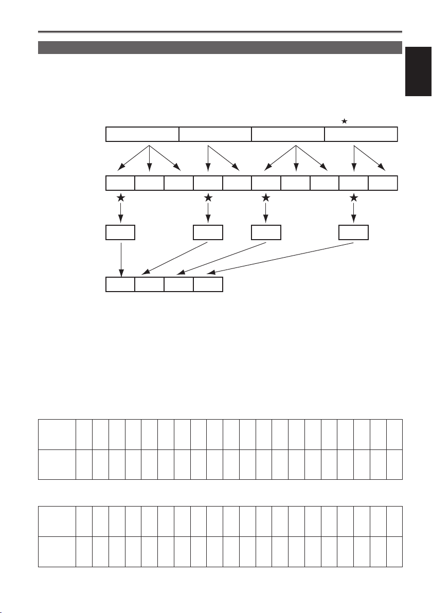
Shooting in progressive mode
Selecting 1080/30P or 1080/24P in the REC
FORMAT option (Page 51) of the setting menu
SCENE FILE screen enables shooting in
progressive mode.
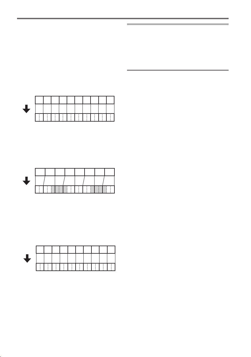
30P mode:
Shoot 30 frames a second in the progressive
mode.
For output and recording, the 30-frame-per-
second signal is converted to 60-field-per-second
interlace.
This mode gives you high quality images.
A B C D E F G H I J
30 P
Ao Ae Bo BeCoCe DoDe Eo Ee Fo FeGoGeHoHe Io Ie Jo Je
60 i
24P mode:
Shoot 24 frames a second in the progressive
mode.
The video signal will be recorded natively.
However, the external output signal is converted
to a 2:3 format, 60 fps interlaced signal.
24 P
A B C D E F G H
Ao Ae Bo BeBoCeCoDeDoDe Eo Ee FoFe FoGeGoHeHoHe
60 i
Note the following when shooting in
progressive mode.
• Set the shutter speed to 1/50 (OFF) for best
results.
• There may be a slight delay to the start
of recording when you use the 24P mode
because 4 frames are recorded at a time.
25P mode:
Shoots 25 frames a second in the progressive
mode.
For output and recording of video signal, the
25-frame-per-second image is converted to
50-field-per-second interlace signal.
This mode gives high quality images.
A B C D E F G H I J
25 P
Ao Ae Bo BeCoCe DoDe Eo Ee Fo FeGoGeHoHe Io Ie Jo Je
50 i
4
Shooting techniques for different targets
Self-portrait shooting
Images in the LCD monitor when it is turned 180°
for self-portrait shooting may appear unusual.
You can make them appear better by reversing
left and right. Go to the setup menus, DISPLAY
SETUP screen, SELF SHOOT, and select
MIRROR. Shooting in mirror mode has no effect on
what you actually shoot and record.
• Images played back by pressing the REC
CHECK button cannot be inverted horizontally.
• Operation status displays during self-portrait
recording
No display: Cannot record (no card, etc.)
: Recording in progress, during transition
to the recording pause mode
: Recording paused (recording standby)
: Warning display
• Only part of the screen display appears.
When [ ] is displayed, turn the LCD monitor
back in the direction of normal recording, and
check what the message says.
• To confirm screen display information on the
viewfinder, turn the LCD monitor to the normal
shooting position.
Zebra pattern
Press the ZEBRA button in the CAM mode to show
the zebra pattern or marker on the viewfinder and
the LCD monitor so you can check the brightness
of the subject.
Parts that may be whited out through over
exposure are shown as a zebra pattern.
• Very bright
• Reflecting parts
ZEBRA button
BARS
ZEBRA OIS
EVF DTL
CH1 SEL
CH2 SEL
)
INT(L
INPUT1
INPUT1
INPUT2
INPUT2
WFM
AUDIO
INPUT1 INPUT2
ON
COUNTER-RESET/TC SET
You can remove most overexposed parts by
adjusting the iris and shutter speed in the manual
mode to remove the areas with zebra patterns.
The display changes as follows each time you
press the ZEBRA button.
ZEBRA 1 → ZEBRA 2
↑ ↓
ZEBRA OFF ← MARKER ON
In the setup menus, DISPLAY SETUP screen,
ZEBRA DETECT1 and ZEBRA DETECT2, set the
brightness for the zebra patterns. (Page 59)
If the ZEBRA DETECT2 item is set to OFF,
ZEBRA2 will not be displayed even if the ZEBRA
button is pressed.
The zebra pattern you have set appears as a
percentage on the display for about 2 seconds.
OFFONOFF
MIC POWER +48V
Shooting
The zebra pattern is displayed in the color bar
as well.
5
Shooting techniques for different targets (continued)
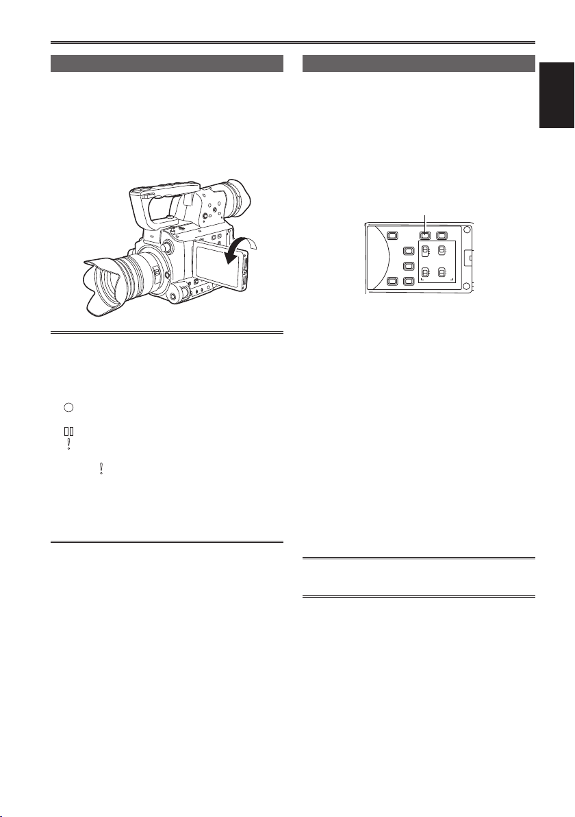
Marker
If you press the ZEBRA button while the zebra
pattern is being displayed, a marker appears in
the center of the display (if you have set the setup
menu, DISPLAY SETUP, Y GET MARKER to ON).
The brightness of the areas near the screen center
can be checked as a percentage (0% to 99%).
“99%↑” appears if the percentage is over 99.
Image level detection area
Marker
99%
Image level
The normal display reappears if you press the
ZEBRA button again.
Checking and displaying shooting status
MENU
EXEC
START/
PUSH-ENTER
STOP 2
+–
AUDIO MON
MEGA
O.I.S.
ON
OFF
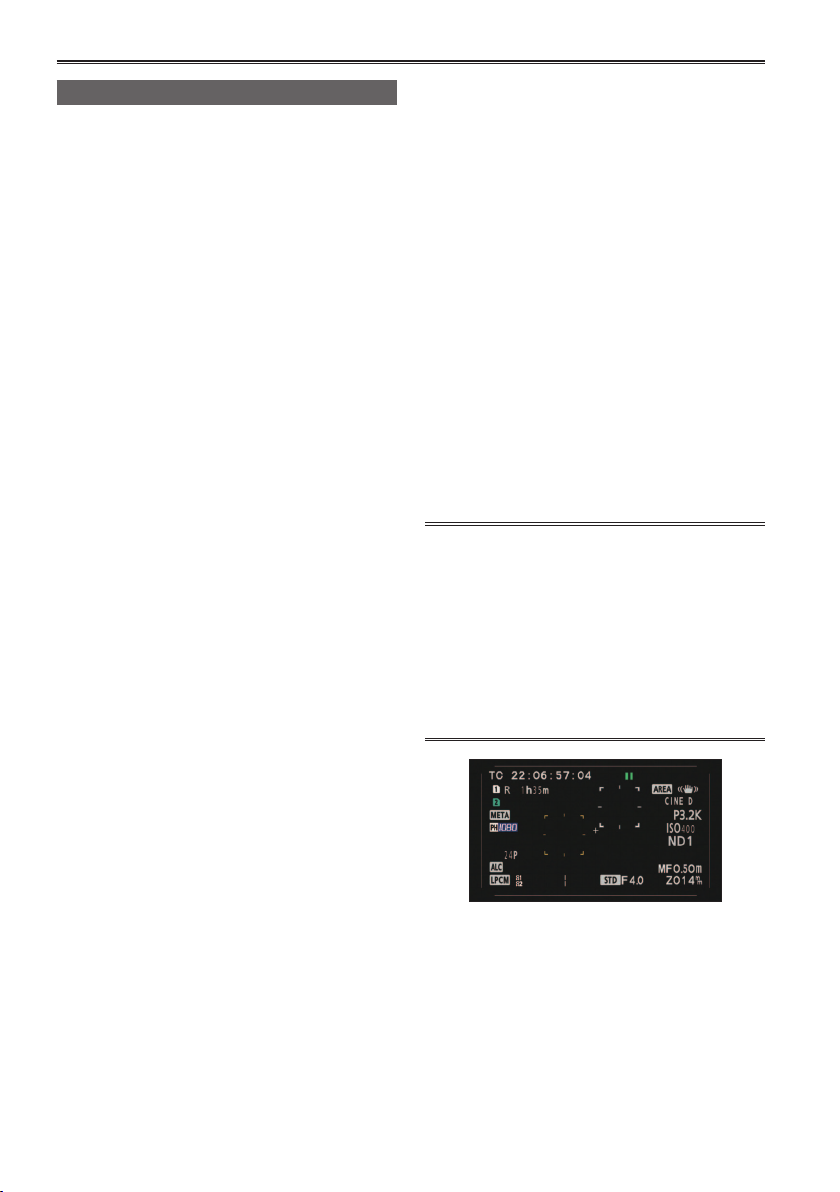
DISP/MODE CHK button
Pressing the DISP/MODE CHK button during
recording or while recording is paused will remove
all displays from the screen except the operation
status display, frame display (such as area),
counter, marker, and safety zone display.
Pressing the DISP/MODE CHK button during
recording or while recording is paused will
remove all displays from the screen except for the
operation status, frame display erea etc., counter,
marker, and safety zone display. Press the button
again to return to the normal display. (Page 50)
This setting will be maintained even if the camera’s
power is turned off by moving the POWER switch to
the OFF position or if the operating mode is changed.
Pressing the DISP/MODE CHK button while the
thumbnail screen is displayed in PB mode will
display the properties of the selected clip.
(Clips can be selected by moving the cursor with
the Operation lever.)
DISP/
POWER
FOCUS
PUSH AUTO
FUNCTION
USER 1
ON
..
OFF
MODE
CHK
MODE
CAM
A
M
PB
∞
CH1
AUDIO
LEVEL
CH2
IRIS
GAIN
WHITE BAL
USER 2
L
B
M
A
H
PRST
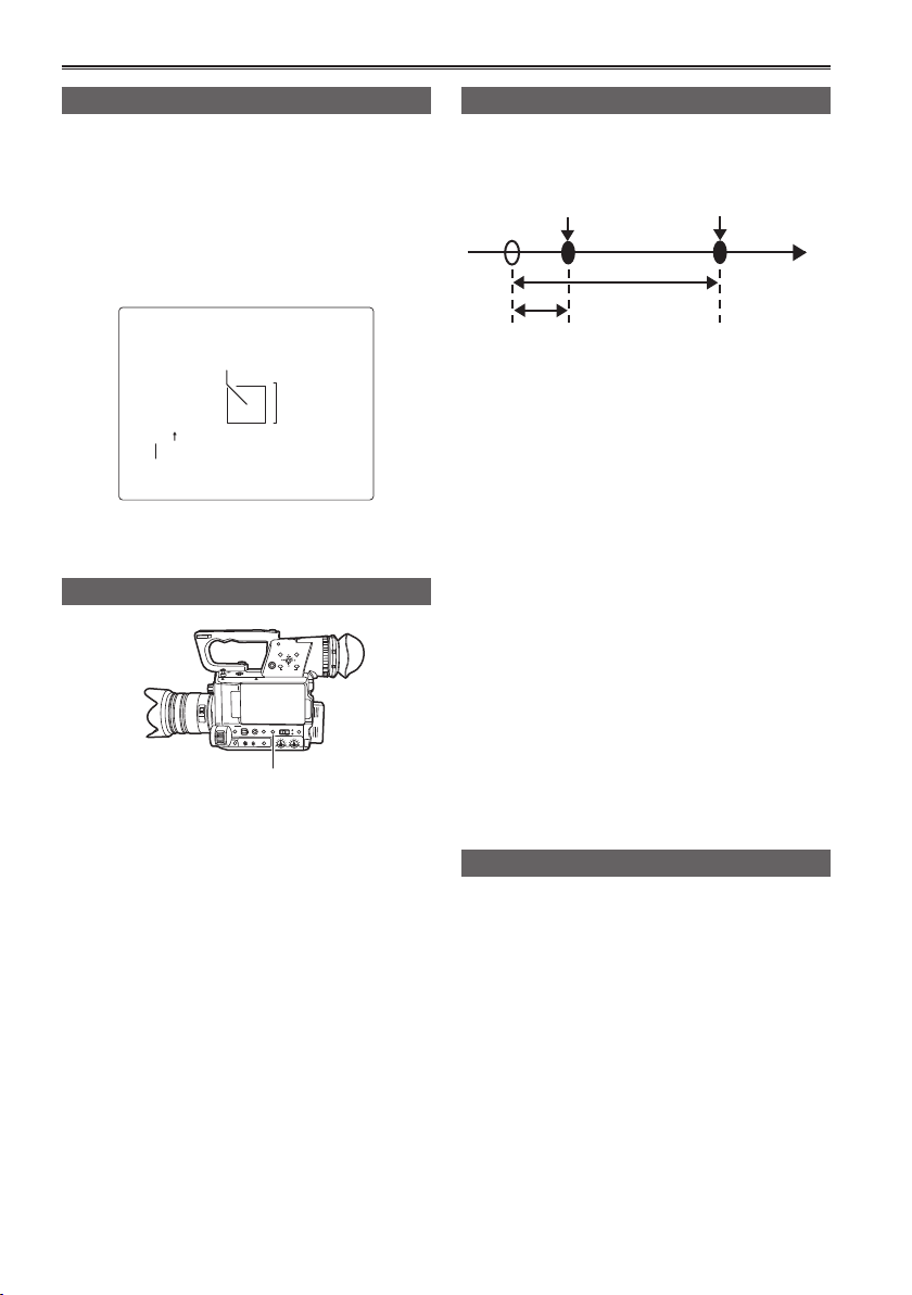
PRE REC
Record video and audio from three seconds before
the time of the operation to begin recording.
Operation to start
recording
Operation to stop
recording
(Time)
Actual recording
time
PRE REC time
Set the PREREC MODE item on the settings
1
menu RECORDING SETUP screen to ON.
PRE-REC will be displayed on the screen.
• When the TCG item on the TC/UB SETUP
screen has been set to REC RUN, the setting
will be automatically changed to FREE RUN.
Press the START/STOP button.
2
Video and audio from approximately 3 seconds
previously will be recorded.
• Recording of the previous 3 seconds of video
and audio may not be possible if recording is
started immediately in the following cases.
ā Immediately after switching from PB mode
to CAM mode
ā Immediately after turning power on
ā Immediately after changing to PREREC
MODE item
• The thumbnail for clips recorded using the
PREREC function will display the image from
when the START/STOP button was pressed.
Relay function
When the remaining space on an SD card is
insufficient during recording, recording can be
continued using the other SD card slot.
Select ON in the RELAY REC item on the settings
menu RECORDING SETUP screen.
• When the remaining space on an SD card is
insufficient during recording, recording will
automatically be continued using the SD card in
the other slot.
• The relay function is not available when an SD
card that cannot be recorded to is inserted in the
SD card slot.
• The camera is capable of continuous recording
for up to 12 hours maximum. This cannot be
extended even if the relay function is used.
6
Variable frame rate (VFR)
This camera can perform low speed (undercrank) and high speed (overcrank) recording without the need
for a frame rate converter (the camera must be set to 1080_24p or 1080_30p).
24P mode:
Shoots 24 frames a second in native mode. The images (shot at 24 frames a second) are recorded into 24
frames as the video signal.
: Valid frames
Camera
24P
1 2 3 4
1 1 1 2 2 3 3 3 4 4
Shooting
1
24PN
• When VFR is set, the INTERVAL REC function, relay recording function, and PRE REC function are
automatically set to OFF, and TCG is automatically set to REC RUN.
• The frame rate cannot be changed during recording.
• VFR shooting is only possible when shooting with REC FORMAT set to 1080_24p, 1080_30p or
1080_25p. VFR shooting does not work in the 720p mode.
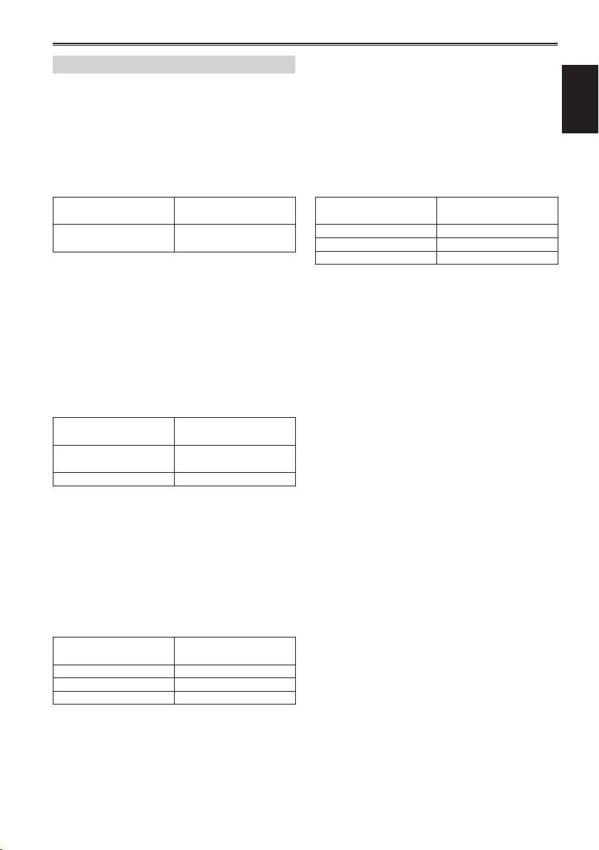
The recording frame rate can be set to any one from the 20 frame rates given in the following table.
There is a slight a difference between the displayed recording frame rate and the actual recording frame
rate. Please refer to the table below.
When SYSTEM FREQ is set to 59.94 Hz
Indicated
recording
frame rate
Actual
recording
frame rate
When SYSTEM FREQ is set to 50 Hz
Indicated
recording
frame rate
Actual
recording
frame rate
60 54 48 44 40 36 34 32 30 28 27 26 25 24 22 21 20 18 15 12
59.94 53.74 47.54 43.96 39.96 35.97 33.88 31.73 29.97 27.83 27.25 25.97 24.98 23.98 21.98 20.75 19.98 17.63 14.99 11.99
50 48 45 42 37 34 32 30 28 27 26 25 24 23 22 21 20 18 15 12
50.00 48.08 45.45 41.67 36.76 34.09 31.82 30.00 27.78 26.79 26.04 25.00 24.00 23.08 22.06 20.83 20.00 17.86 15.00 12.50
1 2 3 4
2 3 4
7

Shooting techniques for different targets (continued)
Native recording
Select 1080/24P recording format from
1
the REC FORMAT option (page 51) on the
settings menu SCENE FILE screen.
From the OPERATION TYPE option (page
2
51) on the settings menu in SCENE FILE
screen, select FILM CAM, set VFR MODE
to ON, and then set the FRAME RATE item
(page 51) to an arbitrary recording frame
rate.
Press the START/STOP button
3
Start native recording in VFR mode.
• Although the audio is not recorded, the sound
is output from the AUDIO OUT terminal, HDMI
terminal, and SDI OUT terminal during setup and
during recording. The audiometer also shows a
deflection.
• During the VFR mode, the camera is set to
manual focus mode.
Standard recording
Select 1080/30P recording format from
1
the REC FORMAT option (page 51) on the
settings menu SCENE FILE screen.
From the OPERATION TYPE option (page
2
51) on the settings menu in SCENE FILE
screen, select FILM CAM, set VFR MODE
to ON, and then set the FRAME RATE item
(page 51) to an arbitrary recording frame
rate.
Press the START/STOP button.
3
Start standard recording in VFR mode.
• Although the audio is not recorded, the
sound is output from the AUDIO OUT
terminal, HDMI terminal, and SDI OUT
terminal during setup and during recording.
The audiometer also shows a deflection.
• During the VFR mode, the camera is set to
manual focus mode.
• 2:2 pull down recording will be applied for a
recording frame rate of 30P.
8
Use of Variable Frame Rate (VFR)
Overcrank shooting
Normal speed shooting for movie production
When producing videos for screening, a frame
rate of 24fps as used in film projection is standard
(x1). By using the settings below, playback with the
same quality as the film projection is possible. Film
like high quality video can be produced through
1080p progressive and CINELIKE Gamma.
Recording format
(REC FORMAT)
1080P/24P
(native recording)
Normal speed shooting for commercial/drama
production
When producing videos for display on television
screen such as HDTV/SDTV broadcast, a frame
rate of 30fps is standard (x1). By using the settings
below, playback with the same quality as broadcast
is possible. Commercials and music videos can be
recorded at film-like high quality, and at a frame
rate suitable for television broadcast.
Recording format
(REC FORMAT)
1080/30P
(2:2 Pull down)
1080/25P 25 fps*
Recording frame rate
(FRAME RATE)
24 fps*
Recording frame rate
(FRAME RATE)
30 fps*
This is a slow motion effect that can be applied
to scenes such as car chases, action, climaxes,
etc. For example, a slow motion effect of 1/2 can
be gained if the VFR recording frame rate is set
to 60fps when recording with the 30P recording
format that specifies the playback frame rate.
1080P progressive movies produce smooth, high
quality slow motion.
Recording format
(REC FORMAT)
1080/24P Less than 25fps*
1080/30P Less than 32fps*
1080/25P Less than 26fps*
* The recording frame rate (FRAME RATE) can be
set to one of 20 values. (page 14)
Recording frame rate
(FRAME RATE)
Shooting
Undercrank shooting
This is a quick motion effect that can be applied
to scenes showing the flow of clouds, people
standing in the middle of crowds, and kung fu, etc.
For example, a quick motion effect of x2 can be
gained if the VFR recording frame rate is set to
12fps when recording with the 24P recording
format that specifies the playback frame rate.
Recording format
(REC FORMAT)
1080/24P Less than 22fps*
1080/30P Less than 28fps*
1080/25P Less than 24fps*
Recording frame rate
(FRAME RATE)
9
Shooting techniques for different targets (continued)
Shooting using the FUNCTION knob
The following types of recording can be carried out
using the FUNCTION knob.
• Area auto focus function
Operates auto focus within an area frame
selected using the FUNCTION knob.
• Area auto iris function
Automatically adjusts the iris value within an area
frame selected using the FUNCTION knob. This
function cannot be set when the FACE DETECT
function has been set.
• Area luminance display
Displays an averaged luminance level within an
area frame selected using the FUNCTION knob.
Select the function from the FUNCTION
1
KNOB option (page 54) on the settings
menu SW MODE screen.
INH: No function is assigned.
FOCUS: Area focus function and area focus
IRIS: Area iris function and area iris meter
YGET: Area luminance display
FOCUS/IRIS:
Simultaneous operation of the area
FOCUS/YGET:
Simultaneous operation of area
bar function (during MENU setting)
function (during MENU setting)
focus function and area iris function,
simultaneous operation of the area
focus bar function/area iris meter
function (during MENU setting)
focus function and area luminance
display, simultaneous operation
of area focus bar function (during
MENU setting)
Press the FUNCTION knob again.
3
• The white frame turns yellow.
• When the frame is yellow, the FUNCTION
knob function set via the MENU operates in
the area inside the frame.
• Pressing the FUNCTION knob once more
returns the yellow frame to the white frame.
• Switching AUTO/MANUAL for FOCUS/IRIS
is normally carried out in the same way.
• The central luminance function does not
operate when the area luminance display is
operating.
• If the FUNCTION knob is held down for more
than 2 seconds, the frame disappears and
the area function is switched off.
Move the FUNCTION knob up and down,
4
and right and left.
• The white frame changes position. Move the
frame to the area you wish to select.
• Press the FUNCTION knob.
• The area function does not operate during face
detection.
• The area function exits when the power switch
is set to OFF or when the camera is switched
to playback mode.
• Auto focus and auto iris may not be available
depending on lens used.
• The area luminance, FOCUS BAR, and IRIS
METER functions are available regardless of
the lens used.
Press the FUNCTION knob.
2
• A white frame is displayed.
• There is no change in the operation of the
camera other than the display of the frame.
10
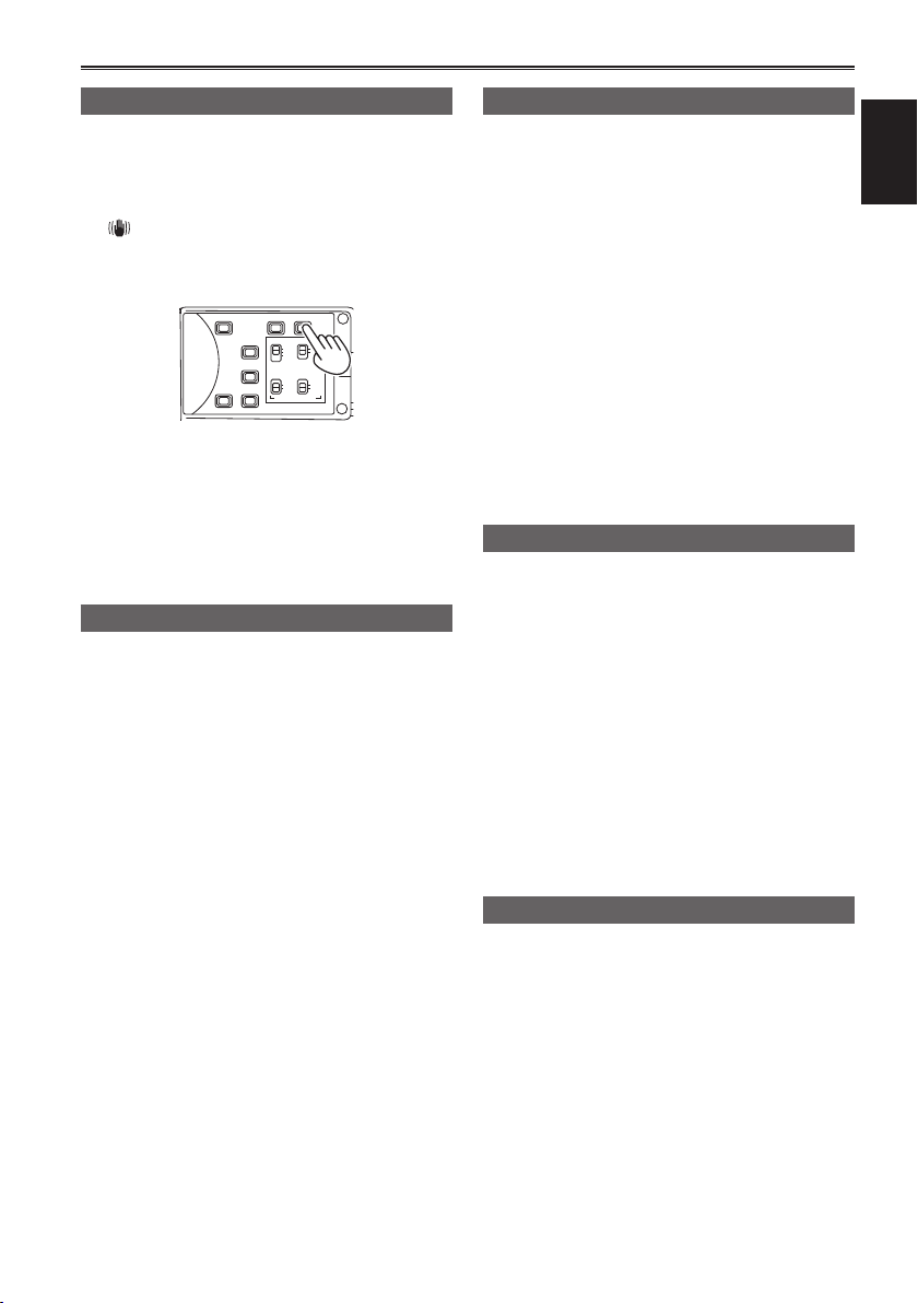
12Shooting techniques for different targets (continued)
Optical Image Stabilizer
Use the Optical Image Stabilizer (OIS) to reduce
the effects of camera shake when shooting by
hand.
Press the OIS button to turn the function on and
off.
appears on the viewfinder and the LCD
monitor when this function is on. Turn the function
off when using a tripod for more natural images.
BARS
ZEBRA OIS
EVF DTL
CH1 SEL
CH2 SEL
)
INT(L
INPUT1
INPUT1
INPUT2
INPUT2
WFM
AUDIO
INPUT1 INPUT2
ON
COUNTER-RESET/TC SET
OFFONOFF
MIC POWER +48V
• For lenses that have an OIS button, only the lens
button is active and the button on the camera is
deactivated. Also, some lenses do not have an
OIS function.
• This function will not be as effective when the
vibration is severe or when tracking a moving
subject.
Adding effects to images
Press the USER button you have allocated to the
BLACKFADE or WHITEFADE feature to add fading
effects to your images. The button’s function is
forcibly canceled during playback or REC CHECK
and also when thumbnails are displayed.
BLACKFADE:
Press the button to fade out to black. Audio also
fades out. Press and hold the button to perform
fade-out, and release the button to start fade-in.
WHITEFADE:
Press the button to fade out to white. Audio also
fades out. Press and hold the button to perform
fade-out, and release the button to start fade-in.
Using the USER buttons
You can allocate one of thirteen features to each of
the three USER buttons.
Use these buttons to change shooting settings
quickly or add effects to the images you are
shooting.
The following features are allocated to the buttons
at the time of shipping.
USER1: IN RED
USER2: ATW LOCK
USER3: REC CHECK
For details, see the setup menus, SW MODE
screen, USER1 SW to USER3 SW. (Page 55)
If you press a USER button to which one of the
functions has been assigned, and then turn OFF
the power or change the mode during operation of
the USER button function, the effect added to the
image will not be retained.
Backlight compensation
Press the USER button you have allocated to the
BACKLIGHT feature when shooting subjects lit
from the back.
BACK LIGHT appears on the screen.
Backlight compensation adjusts the iris so the
subject doesn’t come out dark.
Press the same USER button to turn the feature
off. (In the manual iris mode, the iris status is
retained at the corresponding point even when
backlight compensation is canceled.)
• The backlight compensation function does not
operate with lenses in which AUTO IRIS is not
functioning.
Color bars
Press the BARS button in the CAM mode to output
a color bar screen to a television or monitor so you
can adjust them. Press the button again to turn the
feature off.
• While the color bar is displayed, a test tone of
1 kHz will be output from the headphone terminal
or the AUDIO OUT terminal. There will be no
speaker output.
• The color bar can be recorded by pressing the
START/STOP button.
• The color bar display is canceled when the power
is turned off.
• The BARS button is disabled in the PB mode.
Shooting
11

Wave form monitor function
Adjusting the volume while shooting
An image wave form can be displayed on the LCD
monitor by pressing the WFM button while in CAM
mode.
Press the button again to return to the normal
display.
• Switching the wave form display, vector display,
and wave/vector display is possible from the
WFM item (page 55) in the SW MODE screen of
the settings menu.
• Wave forms will not be displayed in the
viewfinder.
• Wave forms cannot be recorded.
• While wave forms are displayed, use the
viewfinder as well because a part of the recording
screen and screen display will be hidden by wave
forms.
Adjusting the volume
AUDIO MON/ADV
MENU
EXEC
START/
PUSH-ENTER
STOP 2
+–
AUDIO MON
MEGA
O.I.S.
ON
OFF
DISP/
POWER
FOCUS
PUSH AUTO
FUNCTION
USER 1
ON
..
OFF
MODE
CHK
MODE
CAM
A
M
PB
∞
CH1
AUDIO
LEVEL
CH2
IRIS
GAIN
WHITE BAL
USER 2
L
B
M
A
H
PRST
If you are monitoring the sound through
headphones while shooting, you can adjust the
volume with the AUDIO MON/ADV buttons.
• To adjust the recording level. (Page 18)
• Volume adjustments will be memorized if the
power is turned off by moving the POWER switch
to the OFF position.

Shot mark function
The marks attached to the thumbnails of clips
are called shot marks. On the thumbnail screen
monitor you can select only those clips with a
shot mark and display them or play them back.
During recording, when you press the USER
button to which the SHOT MARK function has
been allocated, MARK ON appears in the LCD
monitor or the viewfinder, and a shot mark is set
for the thumbnail of the clip being recorded. If you
press the button again, the shot mark is released.
You can also set or release the shot marks by
performing the thumbnail operations for clips.
(Page 31)
However, note that you cannot set or release shot
marks during playback.
• INVALID appears when you cannot set or release
shot marks.
Index recording
This function allows you to add an index at a
certain point of a clip during the recording or
playback.
Press the USER button allocated to the INDEX
function during recording to record an index signal
at this point of the clip. (Page 55)
Indexes may also be added during playback, and it
is also possible to select only clips with indexes for
display or playback. (Pages 34, 35)
• Up to 100 indexes can be recorded for one
clip.
• When the number of indexes exceeds 100,
INVALID is displayed, and no further indexes
can be added even when the steps for adding
indexes are taken.
• When repeatedly adding indexes, leave a gap
of at least one second between adding one
index and the next. If indexes are added with
a gap of less than one second between them,
only the first operation will be valid.
LAST CLIP function
The most recently recorded clip can be deleted at
the touch of a button by allocating the LAST CLIP
function to any of the USER 1 - 3 buttons.
Press the USER button allocated for the LAST
CLIP function to display YES/NO on the screen.
Select YES to delete the most recently recorded
clip.
• Select NO not to delete the clip.
• If the camera has been switched to PB mode or
the recording format has been changed since
recording was completed, clips cannot be deleted
even if the button is pressed. Clips also cannot
be deleted if the power has been switched off
and back on again.
• Clips cannot be deleted even if the button is
pressed if the memory card has been removed
and reinserted since recording was completed.
CAPTURE function
If the CAPTURE feature is assigned to any of the
USER 1 – 3 buttons, still images can be shot.
• The number of recorded pixels and quality of
the still images cannot be changed.
• This function does not operate when a movie
is being recorded, or when the PRE REC
mode is in use.
• The SD memory card used for recording is the
same as that used for video recording.
Shooting
13

Adjusting the shutter speed
Using the SHUTR/F.RATE dial
DIAL SELECT button
SHUTR/F.RATE dial
Press the DIAL SELECT button.
• The role of the SHUTR/F.RATE dial changes in
the following order.
SHUTTER → SYNCRO SCAN → FRAME RATE
→ DIAL LOCK → SHUTTER →
• SYNCRO SCAN can be selected when the
SHUTTER is set to SYNCRO SCAN. FRAME
RATE can be selected in the FILM CAM mode
when the REC FORMAT is 1080/24P, 30P, and
25P.
To prevent incorrect operation, it is
recommended that you selecting DIAL LOCK
using the DIAL SELECT button after setting.
Setting the SHUTTER
Select the SHUTTER function with the DIAL
1
SELECT button.
Press the SHUTR/F.RATE dial.
2
• The shutter will turn ON/OFF.
• The shutter speed is changed in the order
shown on the following page by turning the
SHUTR/F.RATE dial when the shutter is ON.
• Remember that the faster the shutter speed,
the lower the sensitivity.
• Focusing on the subject would take longer if
the shutter speed is reduced. It is therefore
recommended that the unit be secured to a
tripod, etc. during shooting.
• Under the lighting of electric discharge tubes
such as fluorescent lamps, horizontal bands
may appear on the screen. Adjusting the
shutter speed may improve this condition.
• A subject that quickly crosses the camera may
appear distorted when shot. This is caused due
to the signal reading system of the imaging
element (MOS sensor), and is not a defect.
• At slow shutter speeds (1/2 to 1/15), white,
red, green, or blue dots may appear on the
screen. However, this is not a defect.
Setting the SYNCRO SCAN
Select SYNCRO SCAN from the SHUTTER
1
settings.
Select the SYNCRO SCAN function with the
2
DIAL SELECT button.
Turn the SHUTR/F.RATE dial.
3
• The SYNCRO SCAN shutter speed can be
set.
• The speed of change increases when turning
the SHUTR/F.RATE while holding it down.
• SYNCRO SCAN can also be set from the
SYNCRO SCAN item in the SCENE FILE
screen of MENU settings.
Setting format differs depending on the MENUSCENE FILE-OPERATION TYPE.
FILM CAM: angle display (180.0d etc.)
VIDEO CAM: speed display (1/48.0 etc.)
FRAME RATE setting
Select the FRAME RATE function with the
1
DIAL SELECT button.
Press the SHUTR/F.RATE dial.
2
The camera is in VFR mode.
• The FRAME RATE can be set by turning the
SHUTR/F.RATE dial.
• FRAME RATE can also be set from the
FRAME RATE item in the SCENE FILE
screen of MENU settings.
• Before using the FRAME_RATE function, it
is necessary for the MENU-SCENE FILEOPERATION TYPE to be set to FILM CAM,
and the MENU-SCENE FILE-REC FORMAT
to be set to PH1080/24P or PH1080/30P (or
PH1080/25P).
• The FRAME RATE function cannot be set
when SDI 24PsF is set to ON in the AV IN/
OUT SETUP screen of MENU settings.
• When the FRAME RATE function is set to
ON, the camera is automatically set to manual
focus.
14
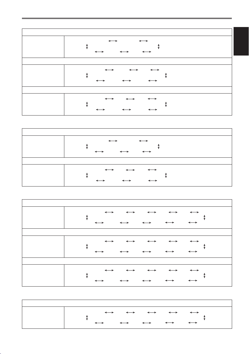
When SYSTEM FREQ = 59.94Hz /OPERATION TYPE = FILM CAM
1080/60P, 1080/60i, 720/60P
Normal (OFF) 1/60
SYNCRO SCAN 1/100 1/120
1/2000 1/1000 1/500 1/250
1080/30P, 720/30P
Normal (OFF) 1/50
SYNCRO SCAN 1/30 1/60 1/120
1/2000 1/1000 1/500 1/250
1080/24P, 720/24P
Normal (OFF) 1/50
SYNCRO SCAN 1/24 1/120
1/60
1/2000 1/1000 1/500 1/250
SYSTEM FREQ = 50Hz /OPERATION TYPE = FILM CAM
1080/50P, 1080/50i, 720/50P
Normal (OFF) 1/50
SYNCRO SCAN 1/60 1/120
1/2000 1/1000 1/500 1/250
1080/25P, 720/25P
Normal (OFF) 1/50
SYNCRO SCAN 1/25 1/120
1/60
1/2000 1/1000 1/500 1/250
SYSTEM FREQ = 59.94Hz /OPERATION TYPE = VIDEO CAM
1080/60P, 1080/60i, 720/60P
Normal (OFF) 1/60
SYNCRO SCAN 1/30
1/2 1/4 1/8 1/15
Shooting
1/2000 1/1000 1/500 1/250
1080/30P, 720/30P
Normal (OFF) 1/50
SYNCRO SCAN 1/30
1/2 1/4 1/8 1/15
1/2000 1/1000 1/500 1/250
1080/24P, 720/24P
Normal (OFF) 1/50
SYNCRO SCAN 1/24
1/2 1/3 1/6 1/12
1/2000 1/1000 1/500 1/250
SYSTEM FREQ = 50Hz /OPERATION TYPE = VIDEO CAM
1080/50P, 1080/50i, 1080/25P, 720/50P, 720/25P
Normal (OFF) 1/50
SYNCRO SCAN 1/25
1/2 1/3 1/6 1/12
1/2000 1/1000 1/500 1/250
1/120 1/100
1/120 1/60
1/120 1/60
1/120 1/60
15

Adjusting the shutter speed (continued)
Synchro scan
The syncro scan shutter speed used when
shooting screens such as a TV screen or computer
monitor is set using the SHUTR/F RATE dial (page
14) or the SYNCRO SCAN option on the settings
menu SCENE FILE screen. (page 51)
• Adjust the shutter speed to match the frequency
of the television or computer monitor to minimize
the horizontal noise that appears when shooting
such subjects.
• By switching to progressive mode you can also
shoot PAL system television screens.
• If the set value of the SYNCRO SCAN item of
settings menu is displayed in gray, it cannot
be used with the current recording format. This
function will only operate for preset values for
each recording format, as listed below.
60i/60P mode: 1/60
30P mode: 1/30
You can change the progressive mode in the
setup menu with REC FORMAT in the SCENE
FILE screen. (Page 51)
16
Switching Audio Input
During shooting, you can record up to two
channels of sound. You can also switch the input
sound to be recorded on each of the channels to
the built-in microphones, external microphones or
audio equipment connected to camera.
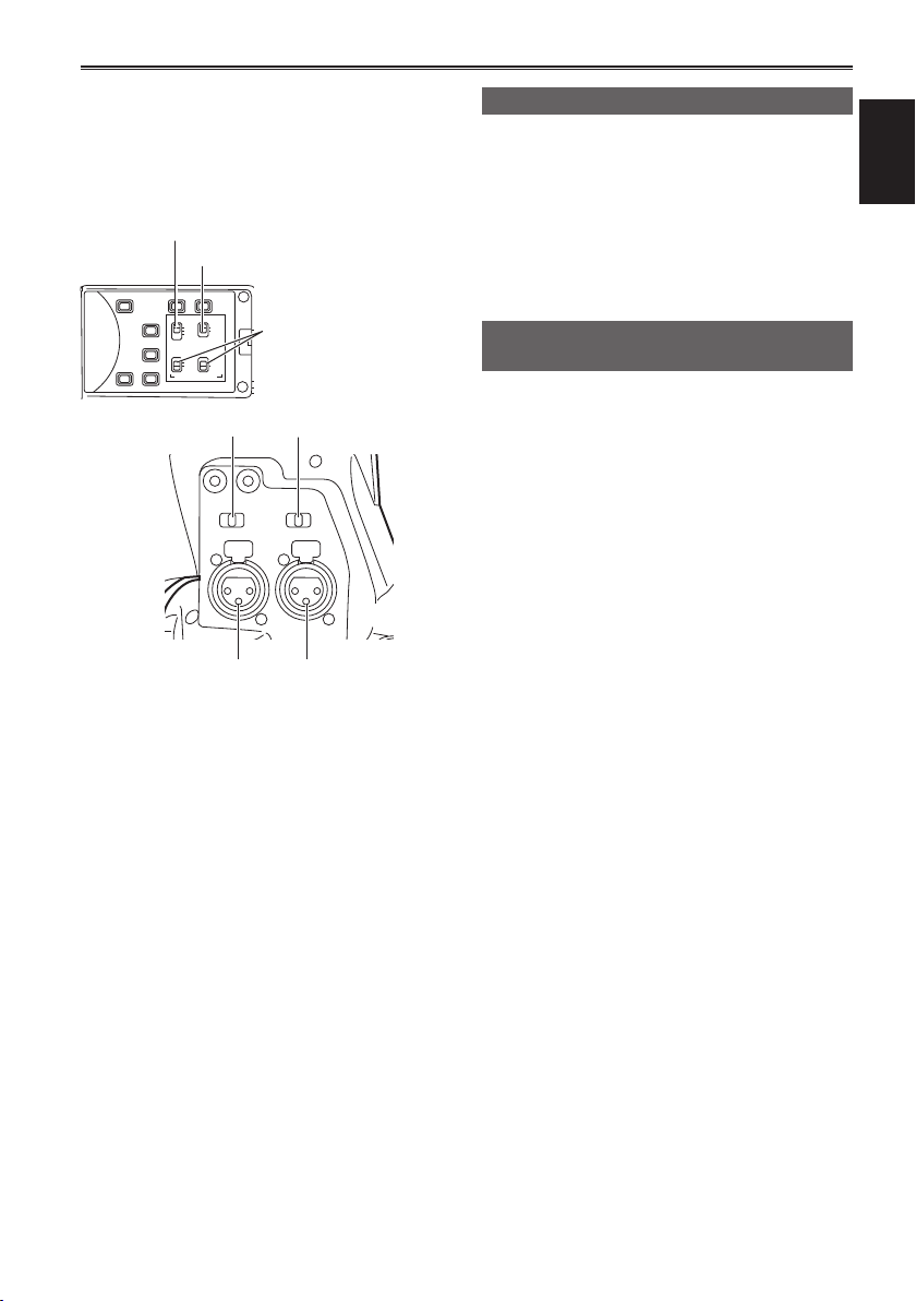
CH1 SELECT switch
CH2 SELECT switch
BARS
ZEBRA OIS
EVF DTL
CH1 SEL
CH2 SEL
)
INT(L
INPUT1
INPUT1
INPUT2
INPUT2
WFM
AUDIO
INPUT1 INPUT2
ON
COUNTER-RESET/TC SET
OFFONOFF
MIC POWER +48V
INPUT 1 switch
INPUT 1/2
(MIC POWER +48V)
switches
INPUT 2 switch
INPUT 1 terminal INPUT 2 terminal
Using the built-in microphone
Switch the CH1 SELECT switch to INT (L).
1
• Audio from the built-in microphone Lch is
recorded to audio channel 1.
Switch the CH2 SELECT switch to INT (R).
2
• Audio from the built-in microphone Rch is
recorded to audio channel 2.
Using an external microphone and audio equipment
Connect an external microphone or audio
1
equipment to the INPUT 1/2 (XLR 3-pin)
terminals. (Page 41)
Use the INPUT 1/2 switches to switch the
2
audio input.
LINE: (audio equipment is connected)
Input level is 0 dBu.
MIC: (an external microphone is connected)
Input level is -50 dBu.
You can change the input level to -60 dBu
in the setup menus, RECORDING SETUP
screen MIC GAIN1 and MIC GAIN2. (Page 56)
Be aware that sensitivity will be higher if
you choose -60 dBu so you will record more
noise.
Shooting
When using the phantom microphone
3
(which requires + 48V power supply),
set the INPUT 1/2 (MIC POWER +48V)
switches to ON.
ON: (When using the phantom microphone)
+48V power supply to INPUT 1/2 terminals.
OFF: (When a phantom microphone is not
connected)
No power supply for INPUT 1/2 terminals.
• The battery will discharge faster if you use a
phantom microphone.
• Set to OFF if you connect equipment not
compatible with +48V. You can damage such
equipment if you leave the setting at ON.
• When using the AG-MC200G (optional), set
the MIC GAIN item to -50 dBu.
17
Switching Audio Input (continued)
Use the CH1 SELECT switch to select the
4
input signal to be recorded to audio channel 1.
INT (L):
Audio from the built-in microphone Lch is
recorded to audio channel 1.
INPUT 1:
Audio from a device connected to INPUT 1
terminal is recorded to channel 1.
INPUT 2:
Audio from a device connected to INPUT 2
terminal is recorded to channel 1.
Use the CH2 SELECT switch to select the
5
input signal to be recorded to audio channel 2.
INT (R):
Audio from the built-in microphone Rch is
recorded to audio channel 2.
INPUT 2:
Audio from a device connected to INPUT 2
terminal is recorded to channel 2.
• When inputting the microphone signal to
channels 1 and 2, connect the microphone to
INPUT 2 and switch both CH1 SELECT and
CH2 SELECT to INPUT 2.
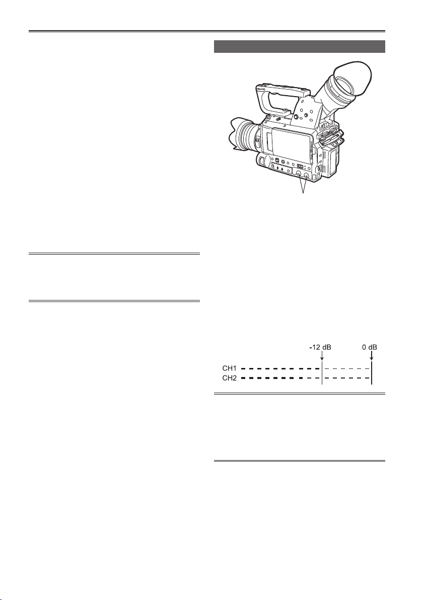
Adjusting the recording level
AUDIO control knobs
Use the AUDIO control knobs to adjust the
recording level of the built-in microphone or of
audio signals input through the INPUT 1/2 (XLR
3-pin) terminals.
To adjust the volume of the sound for monitoring.
(Page 12)
To adjust the recording level of the audio signals,
turn the AUDIO control knobs while referring to
the audio level meter at the bottom left of the
viewfinder and LCD monitor, regardless of the MIC
ALC option setting (page 56) on the RECORDING
SETUP screen of the setting menu.
18
• Check the recording volume level prior to
shooting.
• The recording level of this camera is set
approximately 8 dB higher than Panasonic
broadcasting camera recorders (AJ series
products).

Using scene files
The settings according to the variety of shooting
circumstances are stored SCENE FILE MENU.
They are selected via the SCENE SELECT on the
settings menu SCENE FILE screen.
When the camera-recorder is shipped from the
factory, the following files are stored.
F1:
File suitable for normal shooting.
F2: FLUO.
File suitable for shooting under fluorescent
lights, ie. indoors.
F3: SPARK
File suitable for shooting with fuller variations
of resolution, coloring and contrast.
F4: B-STR
File for broadening the contrast of dark parts,
such as when shooting sunsets.
F5: CINE V
File suitable for shooting movie-like scenes
where the contrast is to be emphasized. (The
recording format remains unchanged even
when the scene file is changed. It must be set
using the REC FORMAT item on the SCENE
FILE screen. (Page 51))
F6: CINE D
File suitable for shooting movie-like
scenes where the dynamic range is to be
emphasized. (The recording format remains
unchanged even when the scene file is
changed. It must be set using the REC
FORMAT item on the SCENE FILE screen.
(Page 51))
Changing scene file settings
The setting value of the scene file can be changed.
Also you can save the changed scene file to each
position of the SCENE FILE dial.
Example: Change the name of the scene file.
Set the POWER switch to ON.
1
Select the scene file to be changed in the
2
SCENE FILE MENU.
In the setup menus, select the SCENE FILE
3
screen.
• For menu operation (Page 44 of Vol.1)
• Operations may also be performed
using buttons on the remote control that
correspond to those on the camera. For
details, see “Description of parts (Remote
control) ”. (Page 23 of Vol.1)
Tilt the Operation lever in the directions
4
and select the NAME EDIT item.
Push the Operation lever (or tilt in the
5
direction), tilt in the
YES, and push the Operation lever again.
direction to select
Shooting
19

Using scene files (continued)
Set a 6-character filename with the
6
Operation lever when the following screen
is displayed.
Set the same as user information. (Page 27)
• Characters that can be set
Space, A to Z, 0 to 9, : < = > ? @ [
If the RESET/TC SET button is pressed
when the filename has been set, the
characters are cleared.
After you finish setting the filename, push
7
the Operation lever.
Select YES on the confirmation screen.
8
• Selecting YES will close the NAME EDIT
screen and confirm all changes.
• Once confirmed, all changed names and
values will be saved even if the power is
switched off or the scene dial is moved.
] ^_-./
20
Saving scene files and other settings on SD Memory Cards
You can save up to four scene file settings or other
settings as files on an SD Memory Card, and you
can also load them from the card.
• In the case of the scene files, the current settings
are automatically saved in the unit, and the
saved data is written on an SD Memory Card.
When data has been read from an SD Memory
Card, the current settings are rewritten at the
same time as the data saved inside the unit.
• The data in all the scene files, F1 to F6, is
rewritten.
If you have saved a scene file
Set the unit’s POWER switch to ON.
1
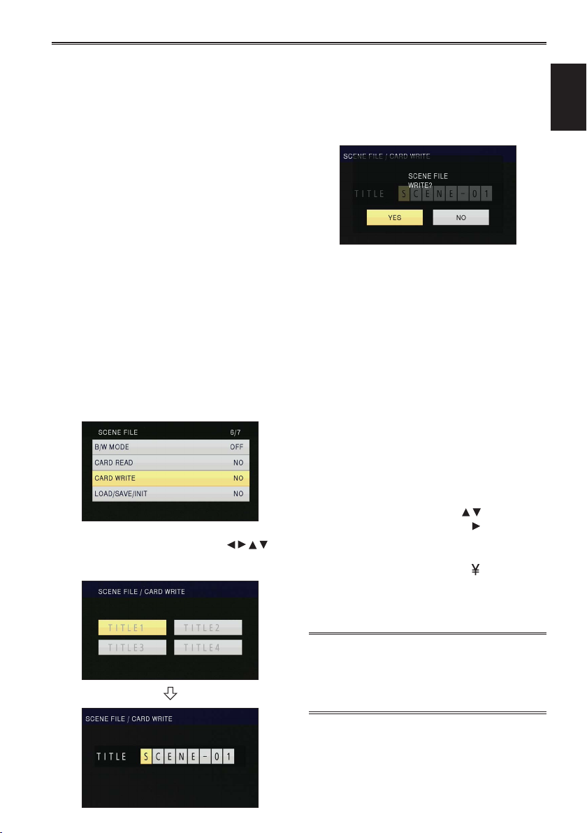
Select the slot number for the SD memory
2
card onto which you wish to save from
the CARD WRITE option on the settings
menu SCENE FILE screen, and press the
OPERATION lever.
For all other settings, select USER FILE. (Page 61)
• For menu operations (Page 44 of Vol.1)
• Operations may also be performed using buttons
on the remote control that correspond to those
on the camera. For details, see “Description of
parts (Remote control)”. (Page 23 of Vol.1)
Push the Operation lever again, select YES
4
when the following screen is displayed, and
push the Operation lever.
• In the following example, SCENE-01 is the
TITLE name. To change the TITLE name,
see the description below.
• “WRITE COMPLETED” is displayed when
writing is complete.
Press the MENU button to exit the menu
5
mode.
To read files
1) Select READ in step
lever.
2) Select the file number and push the Operation
lever.
3) Select YES on the confirmation screen.
READ COMPLETED will be displayed when
reading is complete.
2 and push the Operation
Shooting
Tilt the OPERATION lever in the
3
directions, select a file and then push the
OPERATION lever to set the file name.
To add titles to files
1) Go through steps
2) Tilt the Operation lever in the
select characters, and tilt in the
move to the next character.
The following characters may be inputted.
(Space), A-Z, 0-9, : < = > ? @ [
3) Push the Operation lever when all characters
have been inputted.
4) Select YES on the confirmation screen.
• If WRITE PROTECT appears, release the
protected status of the SD Memory Card.
• If WRITE NG CANNOT ACCESS appears, quit
all other operations (such as playback) before
proceeding.
1 - 3.
directions to
direction to
] ^ _ - . /
21

Clip metadata
You can add the video and audio systems, name
of the videographer, shooting location, text memos
and other information to the video data you have
recorded on the SD Memory Card. This data is
called the clip metadata.
(Display method: Page 38)
There are two kinds of clip metadata: the data that
is recorded automatically during shooting, and the
data in the metadata upload file created on the SD
Memory Card which is loaded in the unit.
(Loading method: Next page)
What the clip metadata consists of
You can set the items underlined below by loading
the metadata upload file on the SD Memory
Card. All other items are set automatically during
shooting.
GLOBAL CLIP ID:
This indicates the global clip ID that shows the
shooting status of the clip.
USER CLIP NAME :
This indicates the name of the clip that the user
VIDEO & AUDIO:
This indicates the recorded image’s FRAME
LENS:
This indicates the MAKER, MODEL, and
ACCESS:
This indicates the CREATOR (name of the
DEVICE:
This indicates the MANUFACTURER
SHOOT:
This indicates the SHOOTER (name of the
∗
1
has set.
RATE, RESOLUTION, PULL DOWN system and
AUDIO.
SERIAL No. of your lens.
person recording), CREATION DATE (recording
date), LAST UPDATE DATE (date on which
the data was last updated) and LAST UPDATE
PERSON (the person who last updated the
data).
(manufacturer of the equipment), SERIAL NO.
(serial number of the equipment) and MODEL
NAME (Equipment model name: AG-AF100 for
this camera-recorder).
videographer) and the PLACE NAME (name of
location).
LOCATION:
This indicates ALTITUDE, LONGITUDE,
LATITUDE, and SOURCE (altitude, longitude,
latitude, information source). Not recorded in
this camera-recorder.
∗
SCENARIO:
2
This indicates the PROGRAM NAME, SCENE
NO. and TAKE NO.
NEWS 1:
This indicates the REPORTER (name of the
reporter) and PURPOSE (purpose of data
collection).
NEWS 2:
This indicates the OBJECT (target of data
collection).
∗
3
MEMO:
This indicates the PERSON (name of the
person who recorded the text memo) and TEXT
(contents of memo).
∗
1
If there is no information in the metadata upload
file, consecutive five-digit numbers will be
applied to the clips in the order that they were
recorded, with the first clip to be recorded being
given the number 0. The USER CLIP NAME
recording method is selectable. Please refer to
the page 23.
∗
2
When SCENARIO is to be input, you must input
the PROGRAM NAME. You cannot input the
SCENE NO. and TAKE NO. only.
∗
3
When MEMO is to be input, you must input
TEXT. You cannot input PERSON only.
• Only printable ASCII characters can be
displayed by this unit.
• Due to the limitations imposed by this unit
on the number of characters which can be
displayed, not all the data can be displayed.
(This does not mean that the data which is not
displayed has been deleted.) Use an AVCCAM
viewer or other program to check all the data.
• Metadata can be produced with AVCCAM
Viewer. (Page 73)
22
24Clip metadata (continued)
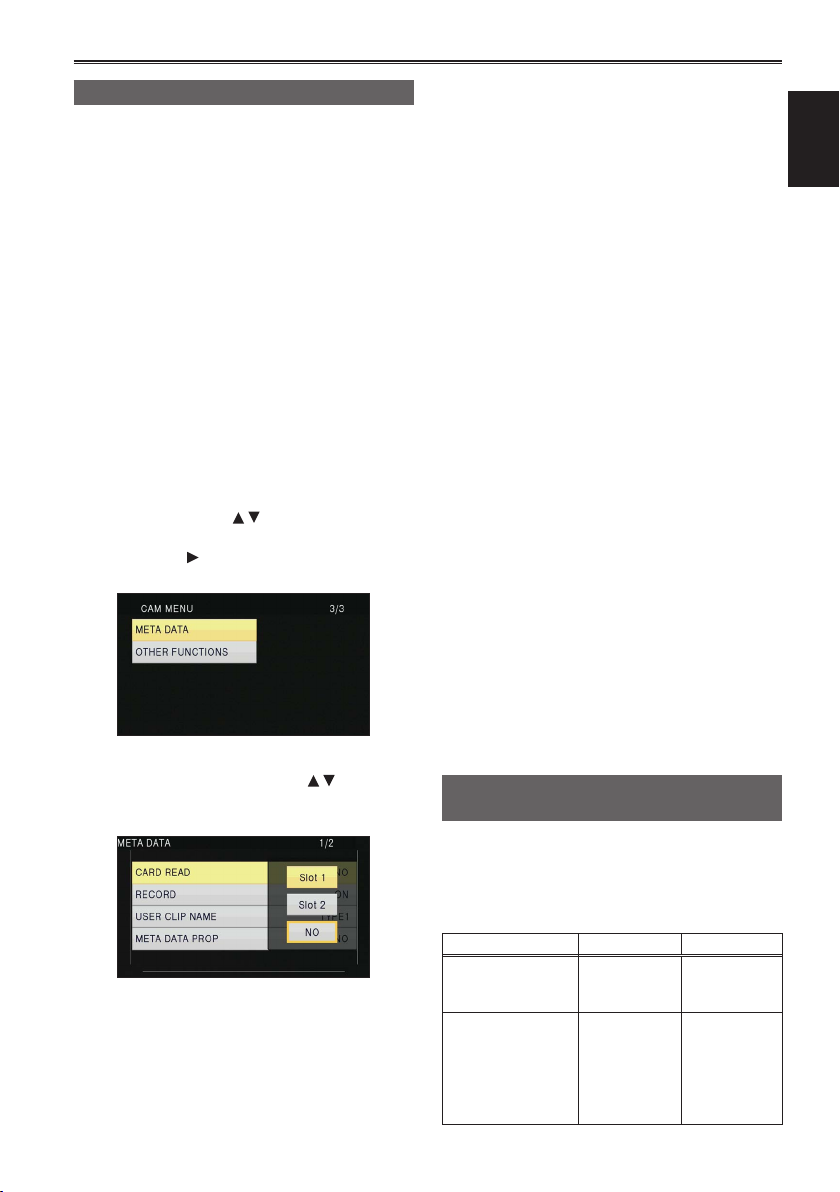
Uploading the metadata (META DATA)
You can perform any of the following operations.
If necessary, make preparations prior to
undertaking the operations.
Loading the metadata
• Insert the SD Memory Card on which the
metadata is recorded into the unit. (For details
on contents of the metadata, see the previous
page.)
Selecting whether to record the metadata on
the SD Memory Card
Initializing the metadata inside the unit
Displaying the metadata inside the unit
Press the mode button and select CAM
1
mode.
Press the MENU button.
2
Menu operation (Page 44 of Vol.1)
Tilt the lever in the directions to select
3
META DATA, and push the Operation lever
(or tilt in the
direction).
ā Up to 8 items of metadata on the SD
Memory Card can be displayed, starting
from the most recent date of production.
ā If characters other than single-byte
alphanumeric characters are used in the
metadata file name to be loaded, they are
displayed as “∗”.
RECORD:
Select this to set whether to record the
metadata to be loaded into the unit
simultaneously on the SD Memory Card. Select
ON to record the metadata or OFF to cancel
the recording, and push the Operation lever.
The factory setting for this mode is OFF.
USER CLIP NAME:
The USER CLIP NAME recording method is
selectable. Please refer to the next column
below.
META DATA PROP:
Select this to display the metadata which has
been recorded in the unit.
CLIP COUNTER RST:
Reset the counter value to 1.
Select whether or not to reset (YES/NO), and
push the Operation lever.
META INIT SET:
Select this to initialize the metadata which
has been recorded in the unit.
Select YES to initialize the metadata or NO
to cancel the initialization, and push the
Operation lever.
Shooting
Tilt the Operation lever in the directions
4
to select item, and push the Operation lever.
CARD READ:
Read metadata set to the SD Memory Card
with the camera.
Move to LOAD, push the Operation lever,
select whether or not to read the metadata
(YES/NO), and push the Operation lever
again.
Press the MENU button to release the menu
5
mode.
Selecting the USER CLIP NAME recording method
Press the MENU button and select META DATA →
USER CLIP NAME to select the recording method.
Two options are available: TYPE1 and TYPE2.
USER CLIP NAME to be recorded
TYPE1 TYPE2
If clip metadata has
been read in
If no clip metadata
has been read in
or if the setting
for recording clip
metadata has been
turned off
Uploaded
data
Sequential 5digit number,
in order of
recording
Uploaded data
+ COUNT
∗
value
Sequential 5digit number,
in order of
recording
23
 Loading...