

Panasonic AFP7X16DW, AFP7Y16R, AFP7Y16T, AFP7Y32T, AFP7Y64T User Manual
...
PROGRAMMABLE CONTROLLER
FP7 Digital Input/Output Unit
User's Manual
Phone: 800.894.0412 - Fax: 888.723.4773 - Web: www.clrwtr.com - Email: info@clrwtr.com

Safety Precautions
Observe the following notices to ensure personal safety or to prevent acci dents.
To ensure that you use this product correctly, read this User’s Manual thoroughly before use.
Make sure that you fully understand the product and information on safety.
This manual uses two safety flags to indicate different levels of danger.
WARNING
If critical situations that could lead to user’s death or serious injury is assumed by
mishandling of the product.
-Always take precautions to ensure the overall safety of your system, so that the whole
system remains safe in the event of failure of this product or other external factor.
-Do not use this product in areas with inflammable gas. It could lead to an explosion.
-Exposing this product to excessive heat or open flames could cause damage to the lithium
battery or other electronic parts.
CAUTION
If critical situations that could lead to user’s injury or only property damage is
assumed by mishandling of the product.
-To prevent excessive exothermic he at or smoke generation, use this product at the values
less than the maximum of the characteristics and performance that are assured i n these
specifications.
-Do not dismantle or remodel the product. It could cause excessive exothermic heat or smoke
generation.
-Do not touch the terminal while turning on electricity. It could lead to an electric shock.
-Use the external devices to function the emergency stop and interlock circuit.
-Connect the wires or connectors securely.
The loose connection could cause excessive exothermic heat or smoke generation.
-Do not allow foreign matters such as liquid, flammable materials, metal s to go into the insid e
of the product. It could cause excessive exothermic heat or smoke generation.
-Do not undertake construction (such as connection and disconnection) while the power
supply is on. It could lead to an electric shock.
Copyright / Trademarks
-This manual and its contents are copyrighted.
-You may not copy this manual, in whole or part, without written con sent of
Panasonic
Industrial Devices SUNX Co., Ltd.
-Windows is a registered trademark of Microsoft Co rporation in the United States an d other
countries.
-All other company names and product names are trademarks or registered trademarks of
their respective owners.
PLC_ORG
Phone: 800.894.0412 - Fax: 888.723.4773 - Web: www.clrwtr.com - Email: info@clrwtr.com
Introduction
Thank you for buying a Panasonic product. Before you use the product, please carefully read
the installation instructions and the users manual, and understand their contents in detail to
use the product properly.
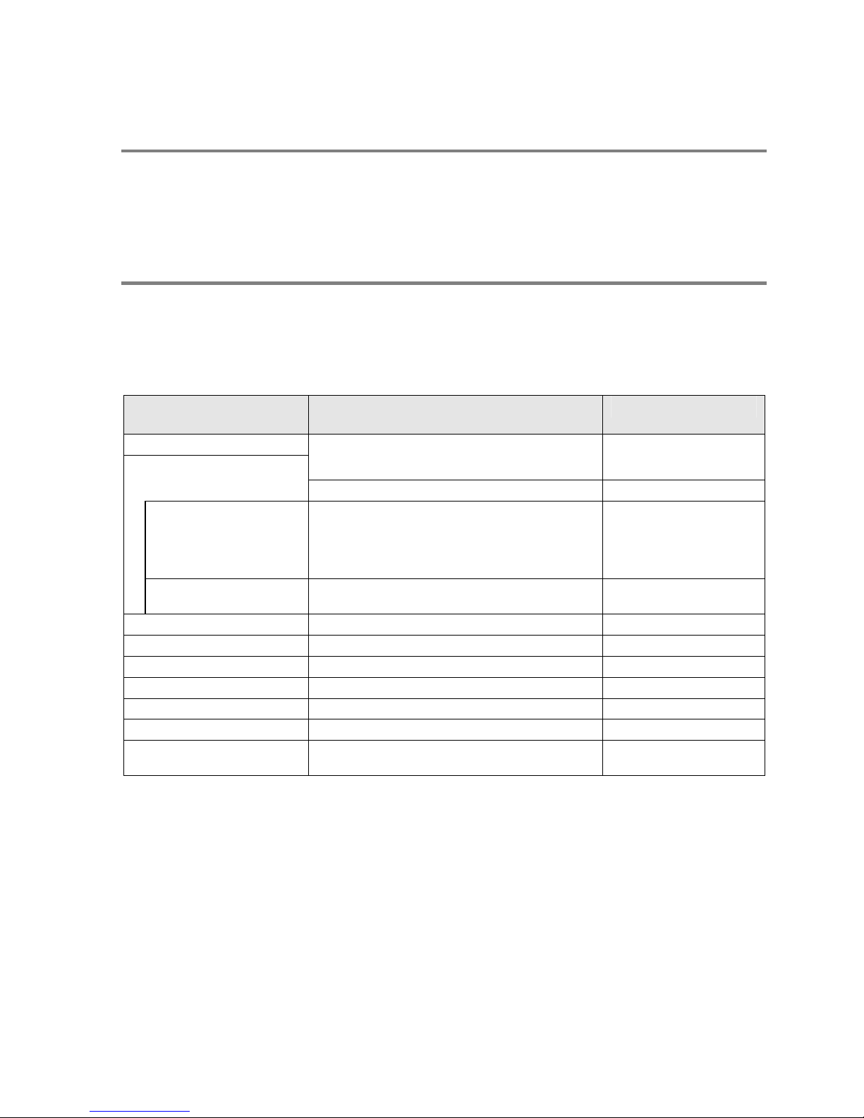
Types of Manual
There are different types of users manua l for the FP7 series, as listed below. Please refer to
a relevant manual for the unit and purpose of your use.
The manuals can be downloaded on our website.
Unit name or purpose of
use
Manual name Manual code
FP7 Power Supply Unit
FP7 CPU Unit Users Manual
(Hardware)
WUME-FP7CPUH
FP7 CPU Unit
FP7 CPU Unit Programming Manual WUME-FP7CPUPGR
Instructi
ons for Built-in
COM Port
FP7 Extension
(Communication)
Cassette
FP7 CPU Unit Users Manual
(COM Port Communication)
WUME- FP7COM
Instructi
ons for Built-in
LAN Port
FP7 CPU Unit Users Manual
(LAN Port Communication)
WUME-FP7LAN
FP7 Digital Input/Output Unit FP7 Digital Input/Output Unit Users Manual WUME-FP7DIO
FP7 Analog Input Unit FP7 Analog Input Unit Users Manual WUME-FP7AIH
FP7 Analog Output Unit FP7 Analog Output Unit Users Manual WUME-FP7AOH
FP7 High-speed Counter unit FP7 High-speed Counter Unit Users Manual WUMJ-FP7HSC
FP7 Positioning Unit FP7 Positioning Unit Users Manual WUME-FP7POSP
PHLS System PHLS System Users Manual WUME-PHLS
Programming Software
FPWIN GR7
FPWIN GR7 Introduction Guidance WUME-FPWINGR7
Phone: 800.894.0412 - Fax: 888.723.4773 - Web: www.clrwtr.com - Email: info@clrwtr.com

Table of Contents
ii
Table of Contents
1. Unit Common Specifications .............................................1-1
1.1 Names and Functions of Parts............................................................... 1-2
1.2 Unit Type................................................................................................ 1-4
2. Specifications......................................................................2-1
2.1 General Specifications ........................................................................... 2-2
2.1.1 Common Specifications...........................................................................2-2
2.1.2 Current Consumption..............................................................................2-3
2.2 Input Unit Specifications......................................................................... 2-4
2.2.1 16-point-type DC Input Unit.....................................................................2-4
2.2.2 32-point-type DC Input Unit.....................................................................2-5
2.2.3 64-point-type DC Input Unit.....................................................................2-6
2.3 Output Unit Specifications...................................................................... 2-7
2.3.1 16-point-type Relay Output Unit..............................................................2-7
2.3.2 16-point Sink-type Transistor Output Unit...............................................2-8
2.3.3 16-point Source-type Transistor Output Unit...........................................2-9
2.3.4 32-point Sink-type Transistor Output Unit.............................................2-10
2.3.5 32-point Source-type Transistor Output Unit.........................................2-12
2.3.6 64-point Sink-type Transistor Output Unit.............................................2-14
2.3.7 64-point Source-type Transistor Output Unit.........................................2-16
2.4 I/O Mixed Unit Specifications ............................................................... 2-18
2.4.1 32-point DC Input/32-point Sink Type Transistor Output......................2-18
2.4.2 32-point DC Input/32-point Source Type Transistor Output..................2-21
2.5 Input Time Constant Switching Function.............................................. 2-24
2.5.1 Overview of Function.............................................................................2-24
Phone: 800.894.0412 - Fax: 888.723.4773 - Web: www.clrwtr.com - Email: info@clrwtr.com

Table of Contents
iii
2.5.2 Setting by FPWIN7 Software Tool ........................................................2-24
3. Wiring ...................................................................................3-1
3.1 Wiring Precautions..................................................................................3-2
3.1.1 Before Wiring...........................................................................................3-2
3.1.2 Input Wiring Precautions.........................................................................3-2
3.1.3 Input Wiring Precautions.........................................................................3-5
3.2 Wiring I/O Unit of Terminal Block Type...................................................3-7
3.2.1 Suitable Wires and Solderless Terminals...............................................3-7
3.2.2 Wiring of Terminal Block.........................................................................3-8
3.3 Wiring Connector-type I/O Unit...............................................................3-9
3.3.1 Wiring with Connectors for Wire-pressed Terminal Cable......................3-9
3.3.2 Assembly of Connector for Wire-pressed Terminal Cable....................3-10
3.3.3 Wiring with Flat Cable Connectors........................................................3-12
Phone: 800.894.0412 - Fax: 888.723.4773 - Web: www.clrwtr.com - Email: info@clrwtr.com

Table of Contents
iv
Phone: 800.894.0412 - Fax: 888.723.4773 - Web: www.clrwtr.com - Email: info@clrwtr.com

1
Unit Common Specifications
Phone: 800.894.0412 - Fax: 888.723.4773 - Web: www.clrwtr.com - Email: info@clrwtr.com

Unit Common Specifications
1-2
1.1 Names and Functions of Parts
8
5
4
3
1
2
(1)
(2)
(8)
(5)
(4)
(3)
8
6
4
3
1
(8)
(1)
(6)
(4)
(3)
8
6
7
4
3
1
(1)
(8)
(7)
(6)
(4)
(3)
(1) I/O indicator LEDs
Indicates the ON/OFF status of the input and output.
(2) Terminal block release lever
Lowering this lever makes it possible to dismount the terminal block from the unit without
disconnecting the wiring. Push the lock button on the bottom of the unit to lock the release
leaver after the terminal block is installed.
(3) DIN hook
This hook is used to mount the unit onto the DIN rail.
(4) Unit Connector
This connector is used to connect the internal circuits of two or more units.
(5) Terminal block
Connect power supplies for the purpose of operating and driving I/O circuits. Crimp terminals
for M3 can be used.
(6) Connector (40P)
Connect power supplies for the purpose of operating and driving I/O circuits. Connectors for
wire-pressed terminal cable or flat cable connectors can be u sed.
(7) Indicator selection switch
Use this switch to select the 32 points in the first half or the 32 points in the second half to be
displayed by the I/O indicator LEDs.
Phone: 800.894.0412 - Fax: 888.723.4773 - Web: www.clrwtr.com - Email: info@clrwtr.com

1.1 Names and Functions of Parts
1-3
(8) Fixing hook
This hook is used to fix two or more units.
Phone: 800.894.0412 - Fax: 888.723.4773 - Web: www.clrwtr.com - Email: info@clrwtr.com
Unit Common Specifications
1-4
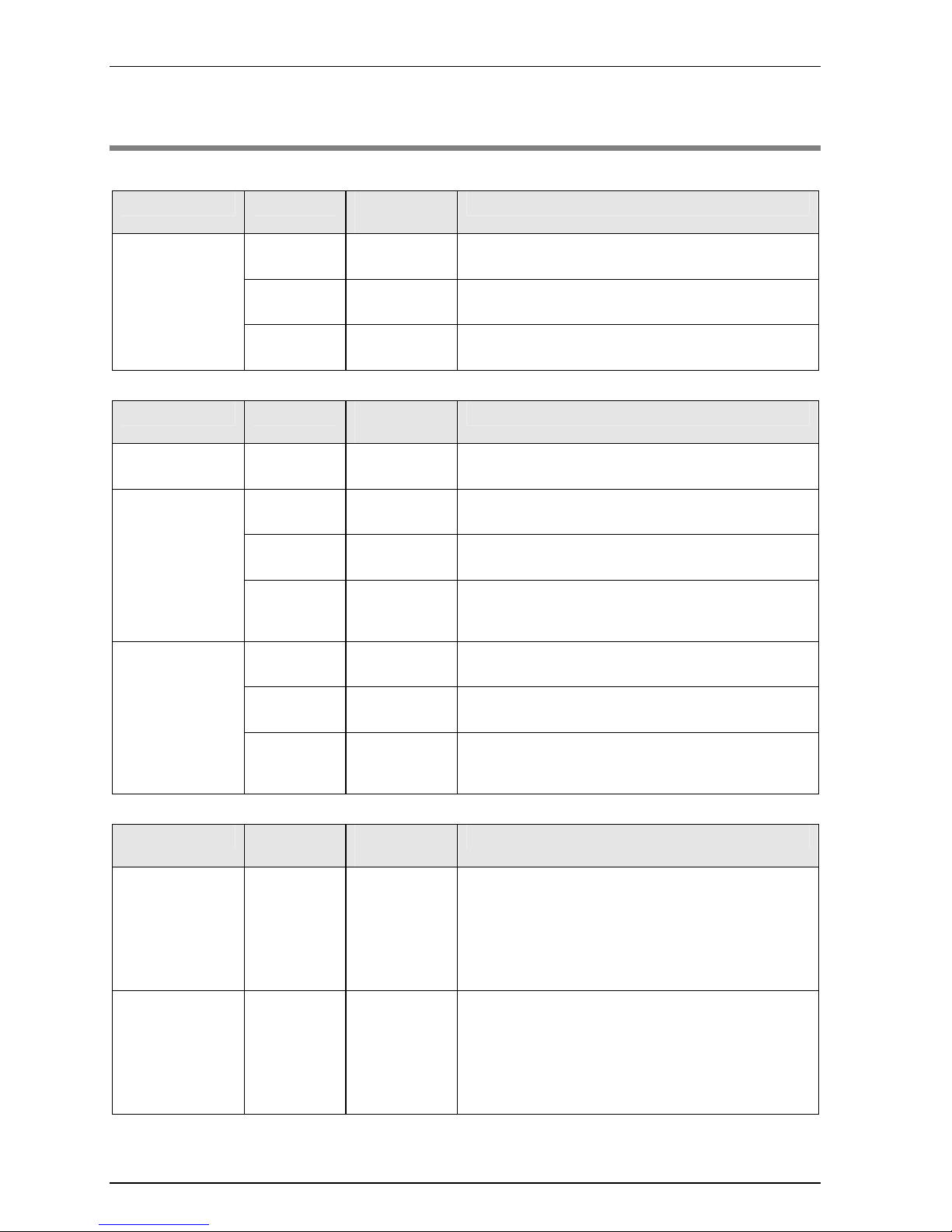
1.2 Unit Type
Input unit
Type Points
Connection
method
Description
16 points Terminal block
12 to 24 V DC (Common polarities + & - common)
Response time switchable
32 points Connector
24 V DC (Common polarities + & - common)
Response time switchable
DC input
64 points Connector
24 V DC (Common polarities + & - common)
Response time switchable
Output unit
Type Points
Connection
method
Description
Relay output 16 points Terminal block
Load current 2 A/1 point and 5 A/1 common
16 points/1 common (with no relay sockets)
16 points Terminal block
Load current 1 A/1 point and 5 A/1 common
16 points/1 common
32 points Connector
Load current 0.3 A/1 point and 3.2 A/1 common
32 points/1 common
Transistor output
sink type
64 points Connector
Load current 0.3 A (8 points: Y0-Y7) and
0.1 A (56 points: Y8-Y3F)
3.2 A/1 common and 32 points/1 common
16 points Terminal block
Load current 1 A/1 point and 5 A/1 common
16 points/1 common
32 points Connector
Load current 0.3 A/1 point and 3.2 A/1 common
32 points/1 common
Transistor output
source type
64 points Connector
Load current 0.3 A (8 points: Y0-Y7), 0.1 A (56 points:
Y8-Y3F)
3.2 A/1 common, 32 points/1 common
I/O mixed unit
Type Points
Connection
method
Description
DC input/
Transistor output
sink type
Input:
32 points
output:
32 points
Connector
• Input specifications
24 V DC (Common polarities + & - common)
Response time switchable
• Output specifications
Load current 0.3 A (8 points: Y0-Y7) and 0.1 A (24
points: Y8-Y1F)
3.2 A/1 common and 32 points/1 common
DC input/
Transistor output
source type
Input:
32 points
output:
32 points
Connector
• Input specifications
24 V DC (Common polarities + & - common)
Response time switchable
• Output specifications
Load current 0.3 A (8 points: Y0-Y7) and 0.1 A (24
points: Y8-Y1F)
3.2 A/1 common and 32 points/1 common
Phone: 800.894.0412 - Fax: 888.723.4773 - Web: www.clrwtr.com - Email: info@clrwtr.com

2
Specifications
Phone: 800.894.0412 - Fax: 888.723.4773 - Web: www.clrwtr.com - Email: info@clrwtr.com

Specifications
2-2
2.1 General Specifications
2.1.1 Common Specifications
Description
Items Description
Ambient temperature 0°C to +55°C
Storage temperature -40°C to +70°C
Ambient humidity 10% to 95% (RH) with no condensation (at +25°C)
Storage humidity 10% to 95% (RH) with no condensation (at +25°C)
Breakdown voltage
<DC input and transistor output>
500 V AC for 1 min. (see note 1)
● Between input terminals and output terminals
● Between output terminals and output terminals (between different common terminals)
● Between input terminals and CPU unit power supply terminals/function earth terminals
●
Between output terminals and CPU unit power supply terminals/function earth terminals
<Relay output>
2300 V AC for 1 min. (see note 1)
● Between output terminals and output terminals (between different common terminals)
● Between output terminals and CPU unit power supply terminals/function earth
terminals
Insulation resistance
(Test voltage:
500 V DC)
<DC input and transistor output>
100MΩ or more
● Between input terminals and output terminals
● Between output terminals and output terminals (between different common terminals)
● Between input terminals and CPU unit power supply terminals/function earth terminals
●
Between output terminals and CPU unit power supply terminals/function earth terminals
<Relay output>
100MΩ or more
● Between output terminals and output terminals (between different common terminals)
● Between output terminals and CPU unit power supply terminals/function earth
terminals
Vibration resistance
Conforming to JIS B 3502 and IEC 61131-2
5 to 8.4 Hz, 3.5-mm-wide single amplitude
8.4 to 150 Hz, acceleration 9.8 m/s
2
10-minute sweeping in X, Y, and Z directions (1 octave/min.)
Shock resistance
Conforming to JIS B 3502 and IEC 61131-2
147 m/s
2
or more, 3 times each in X, Y, and Z directions
Noise resistance
<DC input and transistor output> 1,000 V p-p, pulse widths: 50 ns and 1 μs
<Relay output> 1,500 V p-p, pulse width: 50 ns and 1 μs
Environment Free from corrosive gases and excessive dust.
EU Directive
applicable standard
EMC Directive: EN 61131-2; Low-voltage Directive: EN 61131-2
Overvoltage category Category II
Pollution level Pollution level 2
Note 1) Cutoff current: 5 mA (Factory default setting)
Phone: 800.894.0412 - Fax: 888.723.4773 - Web: www.clrwtr.com - Email: info@clrwtr.com
2.1 General Specifications
2-3
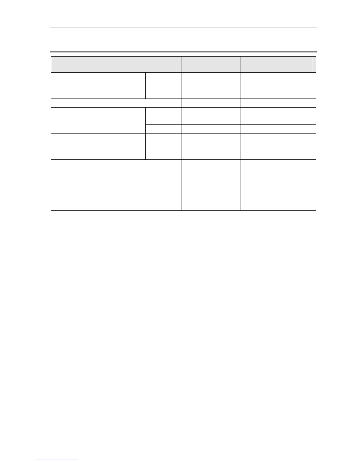
2.1.2 Current Consumption
Product name Model number
Internal current
consumption (24 V DC)
16 points AFP7X16DW 25 mA or less
32 points AFP7X32D2 30 mA or less
DC input unit
64 points AFP7X64D2 35 mA or less
16-point-type relay output unit AFP7Y16R 180 mA or less
16 points AFP7Y16T 35 mA or less
32 points AFP7Y32T 50 mA or less
Transistor output unit (sink type)
64 points AFP7Y64T 75 mA or less
16 points AFP7Y16P 35 mA or less
32 points AFP7Y32P 50 mA or less
Transistor output unit (source type)
64 points AFP7Y64P 75 mA or less
I/O Mixed Unit
32-point DC input
32-point transistor output (sink type)
AFP7XY64D2T 55 mA or less
I/O Mixed Unit
32-point DC input
32-point transistor output (source type)
AFP7XY64D2P 55 mA or less
Phone: 800.894.0412 - Fax: 888.723.4773 - Web: www.clrwtr.com - Email: info@clrwtr.com

Specifications
2-4
2.2 Input Unit Specifications
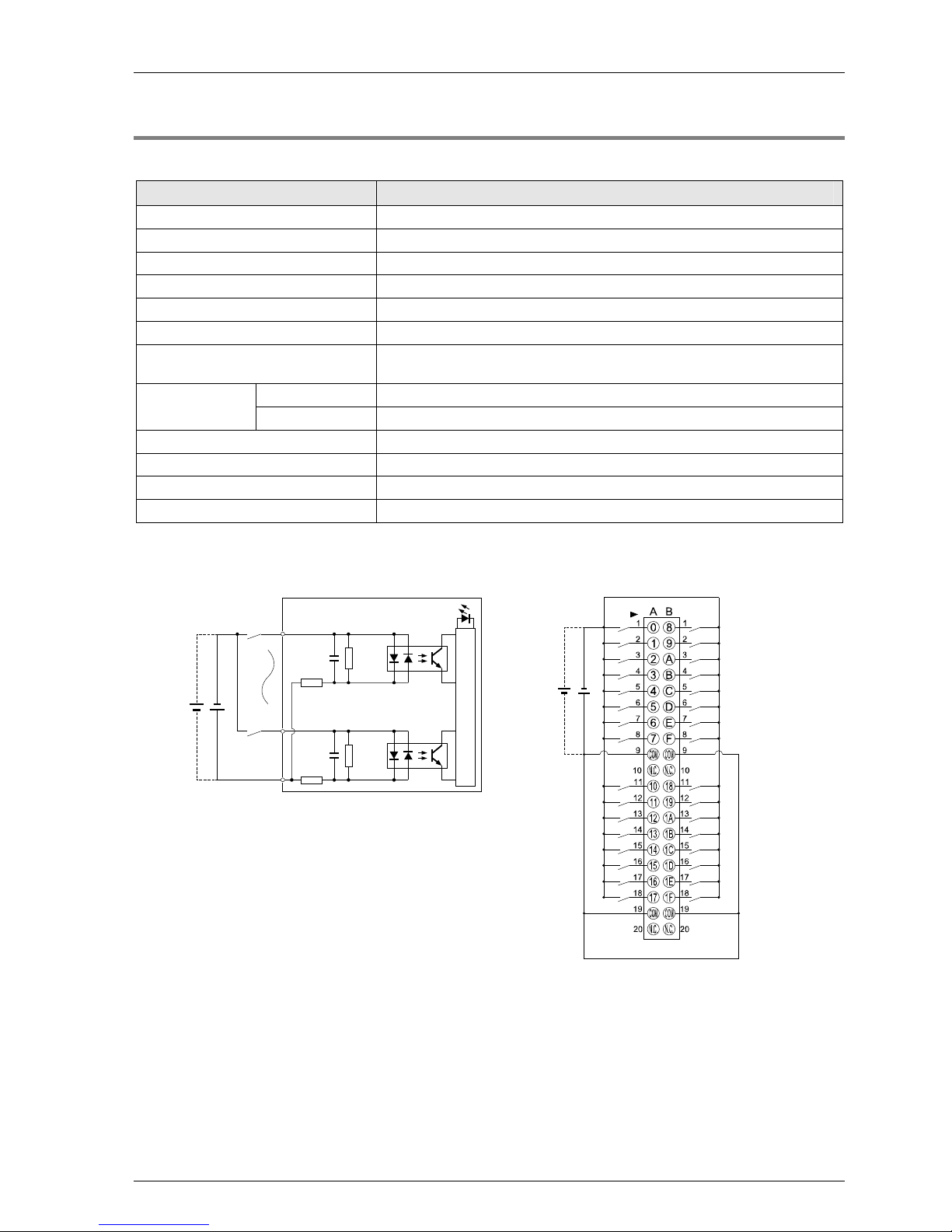
2.2.1 16-point-type DC Input Unit
Description
Items AFP7X16DW
Insulation system Optical coupler
Rated input voltage 12 to 24 V DC
Rated input current Approx. 6 mA (at 24 V DC)
Input impedance Approx. 3.6kΩ
Operating voltage range 10.2 to 26.4 V DC
Minimum ON voltage/Minimum ON
current
9.6 V/2 mA
Maximum OFF voltage/Maximum
OFF current
2.5 V/1 mA
OFF→ON
0.1 ms or less (changeable with time constant switching function at time
of input)
Response time
ON→OFF
0.2 ms or less (changeable with time constant switching function at time
of input)
Input points per common 8 points/1 common
Operating mode indicator 16-point LED indicator (lit in ON state)
External connection method Terminal block connections (M3 terminal screws)
Weight (unit) Approx. 125 g
Internal circuit diagram Terminal layout
X0/X8
X7/XF
COM
1.8kΩ
1.8kΩ
1.8kΩ
1.8kΩ
1.2kΩ
1.2kΩ
Internal circuit
12 to 24V DC
12 to 24V DC
12 to 24V DC
Phone: 800.894.0412 - Fax: 888.723.4773 - Web: www.clrwtr.com - Email: info@clrwtr.com
2.2 Input Unit Specifications
2-5
2.2.2 32-point-type DC Input Unit
Description
Items AFP7X32D2
Insulation system Optical coupler
Rated input voltage 24 V DC
Rated input current Approx. 2.7 mA (at 24 V DC)
Input impedance Approx. 8.2kΩ
Operating voltage range 20.4 to 26.4 V DC
Min. ON voltage/Min. ON current 19.2 V/2.5 mA
Max. OFF voltage/Max. OFF
current
5 V/1.5 mA
OFF→ON 0.2 ms max. (changeable with constant switching function at time of input)
Response time
ON→OFF 0.2 ms max. (changeable with constant switching function at time of input)
Input points per common 32 points/1 common
Operating mode indicator 32-point LED indicator (lit in ON state)
External connection method Connector connections (40P conforming to MIL standards)
Weight (unit) Approx. 95 g
Internal circuit diagram Terminal layout
X0
X1F
COM
2
4V D
C
8.2kΩ
8.2kΩ
750Ω
750Ω
Internal circuit
2
4V D
C
The COM terminals are connected internally.
Phone: 800.894.0412 - Fax: 888.723.4773 - Web: www.clrwtr.com - Email: info@clrwtr.com

Specifications
2-6
2.2.3 64-point-type DC Input Unit
Description
Items AFP7X64D2
Insulation system Optical coupler
Rated input voltage 24 V DC
Rated input current Approx. 2.7 mA (at 24 V DC)
Input impedance Approx. 8.2kΩ
Operating voltage range 20.4 to 26.4 V DC
Min. ON voltage/Min. ON current 19.2 V/2.5 mA
Max. OFF voltage/Max. OFF current 5 V/1.5 mA
OFF→ON
0.2 ms max. (changeable with constant switching function at time of
input)
Response time
ON→OFF
0.2 ms max. (changeable with constant switching function at time of
input)
Input points per common 32 points/1 common
Operating mode indicator 32-point LED indicator (lit in ON state)
External connection method Connector connections (40P conforming to MIL standards)
Weight (unit) Approx. 110 g
Internal circuit diagram Terminal layout
X0/X20
X1F/X3F
COM
24V DC
8.2kΩ
8.2kΩ
750Ω
750Ω
Internal circuit
Limits on number of
simultaneously ON points
Refer to the following figure and reduce the
number of input points that are simultaneously
turned ON.
24V D
C
CN1 CN2
24V DC
The COM terminals in the same connector are connected
internally.
Phone: 800.894.0412 - Fax: 888.723.4773 - Web: www.clrwtr.com - Email: info@clrwtr.com
 Loading...