

Panasonic AFP7CPS41E, AFP7CPS31E, AFP7X16DW, AFP7Y16R, AFP7Y16T User Manual
...
Phone: 800.894.0412 - Fax: 888.723.4773 - Web: www.clrwtr.com - Email: info@clrwtr.com

Safety Precautions
Observe the following notices to ensure personal safety or to prevent accidents.
To ensure that you use this product correctly, read this User’s Manual thoroughly before use.
Make sure that you fully understand the product and information on safety.
This manual uses two safety flags to indicate different levels of danger.
If critical situations that could lead to user’s death or serious inj ury is assumed by
mishandlin g of t he product.
WARNING
-Always take precautions to ensure the overall safety of your system, so that the whole
system remains safe in the event of failure of this product or other external factor.
-Do not use this product in areas with inflammable gas. It could lead to an explosion.
-Exposing this product to excessive heat or open flames could cause damage to the lithium
battery or other electronic parts.
-Battery may explode if mistreated. Do not recharge, disassemble or dispose of fire.
If critical s i tuations that could lead to user’s injury or only property damage is
assumed by mishandling of the product.
CAUTION
-To prevent excessive exothermic heat or smoke generation, use this product at the values
less than the maximum of the characteristics and performance that are assured in these
specifications.
-Do not dismantle or remodel the product. It could cause excessive exothermic heat or smoke
generation.
-Do not touch the terminal while turning on electricity. It could lead to an electric shock.
-Use the external devices to function the emergency stop and interlock circuit.
-Connect the wires or connectors securely.
The loose connection could cause excessive exothermic heat or smoke generation.
-Ground the protective earth (PE) terminal (Class D grounding). Failure to do so could lead to
an electric shock.
-Do not allow foreign matters such as liquid, flammable materials, metals to go into the inside
of the product. It could cause excessive exothermic heat or smoke generation.
-Do not undertake construction (such as connection and disconnection) while the power
supply is on. It could lead to an electric shock.
Copyright / Trademarks
-This manual and its contents are copyrighted.
-You may not copy this manual, in whole or part, without written co nsent of
Panasonic
Industrial Devices SUNX Co., Ltd.
-Windows is a register ed trademark of Microsoft Corporation in the U n ite d States and other
countries.
-Ethernet is a registered trademark of Fuji Xerox Co., Ltd. and Xerox Corp.
-All other company names and product names are trademarks or registered trademarks of
their respective owners.
PLC_BATPE_ET
Phone: 800.894.0412 - Fax: 888.723.4773 - Web: www.clrwtr.com - Email: info@clrwtr.com

Introduction
Thank you for buying a Panasonic product. Before you use the product, please carefully read
the installation instructions and the users manual, and understand their contents in detail to
use the product properly.
Types of Manual
There are different types of users manual for the FP7 series, as listed below. Please refer to
a relevant manual for the unit and purpose of your use.
The manuals can be downloaded on our website.
Unit name or purpose of
use
Manual name Manual code
FP7 Power Supply Unit
FP7 CPU Unit Users Manual (Hardware) WUME-FP7CPUH
FP7 CPU Unit Command Reference Manual WUME-FP7CPUPGR
FP7 CPU Unit Users Manual
(Logging Trace Function)
WUME-FP7CPULOG
FP7 CPU Unit
FP7 CPU Unit Users Manual (Security Function) WUME-FP7CPUSEC
Instructions
for Built-in
LAN Port
FP7 CPU Unit Users Manual
(LAN Port Communication)
WUME-FP7LAN
Instructions
for Built-in
COM Port
FP7 Extension Cassette
(Communication)
(RS-232C/RS485 type)
FP7 series Users Manual (SCU communication) WUME-FP7COM
FP7 Extension Cassette
(Communication)
(Ethernet type)
FP7 series Users Manual (Communication
cassette Ethernet type)
WUME-FP7CCET
FP7 Extension (Function)
Cassette
Analog Cassette
FP7 Analog Cassette Users Manual
WUME-FP7FCA
(Upcoming)
FP7 Digital Input/Output Unit FP7 Digital Input/Output Unit Users Manual WUME-FP7DIO
FP7 Analog Input Unit FP7 Analog Input Unit Users Manual WUME-FP7AIH
FP7 Analog Output Unit FP7 Analog Output Unit Users Manual WUME-FP7AOH
FP7 High-speed counter Unit FP7 High-speed counter Unit Users Manual WUME-FP7HSC
FP7 Pulse Output Unit FP7 Pulse Output Unit Users Manual
WUME-FP7PG
(Upcoming)
FP7 Positioning Unit FP7 Positioning Unit Users Manual WUME-FP7POSP
FP7 Serial Communication
Unit
FP7 series Users Manual (SCU communication) WUME-FP7COM
PHLS System PHLS System Users Manual WUME-PHLS
Programming Software
FPWIN GR7
FPWIN GR7 Introduction Guidance WUME-FPWINGR7
Phone: 800.894.0412 - Fax: 888.723.4773 - Web: www.clrwtr.com - Email: info@clrwtr.com

Table of Contents
Selection of CPU Units
Note the following points when selecting a CPU unit.
Specification changes of CPU unit
The firmware version of CPU units has been changed in accordance with the extension of
the specifications. Specify units with new model numbers.
Conventional
model number
(Ver.1)
New model number
(Ver.2)
Program
capacity
Ethernet
function
With Encryption
function
No Eencryption
function
With Encryption
function
196K steps Available AFP7CPS4E
→
AFP7CPS41E AFP7CPS41ES
Available AFP7CPS3E
→
AFP7CPS31E AFP7CPS31ES
120K steps
Not available AFP7CPS3
→
AFP7CPS31 AFP7CPS31S
The CPU units Ver.2 are upward compatible with the conventional Ver.1.
For using CPU units Ver.2, Ver.2.0 or later version of FPWIN GR7 is required.
For using the projects (programs, comments and configuration data) created for the
conventinal CPUs Ver.1, the projects must be converted to the projects for CPU units Ver.2
using the "Convert PLC Type" function of the tool software.
For using the units released after December 2013 or add-on cassettes, Ver.2 or later version
of CPU unit is required.
The layout of the operation monitor LEDs on the CPU units has been changed.
Regulations on Encryption function in China
Some CPU units have the encryption fu nction which encrypts a part or all parts of programs
in projects.
In China, the types equipped with the encryption function cannot be used as they are subje c t
to "Regulation of Commercial Encryption Codes". For using machines or systems
incorporating FP7 series in China, or exporting and importing them, select the types without
the encryption function.
Phone: 800.894.0412 - Fax: 888.723.4773 - Web: www.clrwtr.com - Email: info@clrwtr.com

i
Table of Contents
1. Overview ..............................................................................1-1
1.1 System Configuration .............................................................................1-2
1.1.1 Units........................................................................................................1-2
1.2 Restrictions on Combinations of Units....................................................1-4
1.2.1 Common Restrictions on Each Unit........................................................1-4
1.2.2 Restrictions on the Number of Installed Units.........................................1-4
1.2.3 Restrictions on the Combination of Extension Cassettes.......................1-4
1.2.4 Restrictions on Communication Functions to be Used...........................1-5
1.2.5 Unit to be Used and Applicable Versions of CPU Unit and FPWIN GR71-5
1.3 Selection of Power Supply and Restrictions on Combination.................1-6
1.3.1 Power Supply for Internal Circuit.............................................................1-6
1.3.2 Power Supply for External Circuit...........................................................1-9
1.4 Programming Tools ..............................................................................1-10
2. Names and Functions of Parts...........................................2-1
2.1 CPU Unit.................................................................................................2-2
2.2 Power Supply Unit..................................................................................2-4
3. I/O Number Allocation.........................................................3-1
3.1 Basics of I/O Allocation...........................................................................3-2
3.1.1 How to Count the I/O Numbers...............................................................3-2
3.1.2 Concept of I/O Number Allocation...........................................................3-2
3.1.3 Occupied I/O Points for Each Unit ..........................................................3-3
Phone: 800.894.0412 - Fax: 888.723.4773 - Web: www.clrwtr.com - Email: info@clrwtr.com

ii
Table of Contents
3.2 Optional Allocation Using FPWIN GR7.................................................. 3-4
3.2.1 Registration of a Unit to be Used and the Starting Word Number..........3-4
3.2.2 Optional Settings in the “Unit Selection” Dialog Box...............................3-6
3.3 Mount Allocation Using FPWIN GR7...................................................... 3-7
3.3.1 Mount Registration of a Unit to be Used and the Starting Word Number3-7
3.3.2 Changing the Starting Word Number......................................................3-8
3.4 Automatic Allocation............................................................................... 3-9
3.4.1 Allocation without Using FPWIN GR7.....................................................3-9
3.5 I/O Map Registration ............................................................................ 3-10
3.5.1 I/O Map Registration .............................................................................3-10
3.5.2 I/O Map Clearance................................................................................3-10
4. Installation and Wiring........................................................4-1
4.1 Installation.............................................................................................. 4-2
4.1.1 Installation Environment and Space........................................................4-2
4.1.2 Attaching Units........................................................................................4-4
4.1.3 DIN Rail Attachment................................................................................4-6
4.2 Wiring the Power Supply........................................................................4-8
4.2.1 Common Precautions..............................................................................4-8
4.2.2 Wiring for Power Supply Units ................................................................4-9
4.2.3 Wiring for the Power Supply Part of the CPU Unit................................4-10
4.2.4 Grounding..............................................................................................4-11
4.3 Safety Measures .................................................................................. 4-12
4.3.1 Safety Circuit.........................................................................................4-12
4.3.2 Momentary Power Drop ........................................................................4-12
4.3.3 Alarm Output.........................................................................................4-13
5. Operation.............................................................................5-1
5.1 Before Powering On...............................................................................5-2
Phone: 800.894.0412 - Fax: 888.723.4773 - Web: www.clrwtr.com - Email: info@clrwtr.com

Table of Contents
iii
5.1.1 Check Points...........................................................................................5-2
5.1.2 Procedures before Starting Operation ....................................................5-3
5.2 RAM/ROM Operation..............................................................................5-4
5.2.1 Transmission of the Project.....................................................................5-4
5.2.2 Operations following Powering On..........................................................5-5
5.2.3 Data Hold During Power Failure .............................................................5-6
5.2.4 Online Editing..........................................................................................5-6
5.3 Backing Up the Project...........................................................................5-7
5.3.1 Transmission from the Execution Memory RAM to the Backup Memory
ROM2......................................................................................................5-7
5.3.2 Transmission from the Backup Memory ROM2 to the Execution Memory
RAM/ROM1.............................................................................................5-8
5.3.3 Operations following Powering On/Off....................................................5-8
5.4 SD Memory Card Operation...................................................................5-9
5.4.1 Preparing SD Memory Cards..................................................................5-9
5.4.2 How to Insert an SD Memory Card.......................................................5-10
5.4.3 Saving an Execution File for SD Memory Card Operation ...................5-11
5.4.4 Provisional Operation by an SD Memory Card.....................................5-12
5.4.5 Transmission from an SD Memory Card to the Execution Memory......5-14
5.4.6 Precautions Concerning SD Memory Card Operation..........................5-15
6. Troubleshooting..................................................................6-1
6.1 Self-Diagnosis Function..........................................................................6-2
6.1.1 CPU Unit's Operation Monitor LED.........................................................6-2
6.1.2 Operation at the Time of Error ................................................................6-2
6.2 What to Do If an Error Occurs ................................................................6-3
6.2.1 ERROR LED Flashes on the CPU Unit ..................................................6-3
6.2.2 PROG Mode Does Not Change to RUN.................................................6-4
6.2.3 ALARM LED Turns ON on the CPU Unit................................................6-4
6.2.4 POWER LED Does Not Turn ON on the Power Supply Unit..................6-5
6.2.5 A Protect Error Message Appears ..........................................................6-5
6.2.6 If Expected Output Is Not Available ........................................................6-6
Phone: 800.894.0412 - Fax: 888.723.4773 - Web: www.clrwtr.com - Email: info@clrwtr.com

iv
Table of Contents
7. Maintenance and Inspection..............................................7-1
7.1 Handling of Backup Battery.................................................................... 7-2
7.1.1 Functions of Backup Battery ...................................................................7-2
7.1.2 Replacement of Backup Battery..............................................................7-3
7.1.3 Lifetime and Replacement Interval of Backup Battery............................7-4
7.2 Inspection...............................................................................................7-5
8. Specifications......................................................................8-1
8.1 CPU Unit Specifications......................................................................... 8-2
8.1.1 General Specifications ............................................................................8-2
8.1.2 Performance Specifications.....................................................................8-4
8.1.3 CPU Unit Communication Specifications................................................8-6
8.1.4 Operation Memory Area..........................................................................8-8
8.1.5 List of System Relays............................................................................8-10
8.1.6 List of System Data Registers...............................................................8-17
8.1.7 Error Codes Table.................................................................................8-20
8.2 Power Supply Unit Specifications......................................................... 8-24
8.2.1 General Specifications ..........................................................................8-24
8.2.2 Performance Specifications...................................................................8-25
8.2.3 Alarm Output Specifications..................................................................8-25
8.3 Dimensions........................................................................................... 8-26
8.3.1 Power Supply Unit.................................................................................8-26
8.3.2 CPU Unit................................................................................................8-27
8.3.3 Terminal Block Type Unit......................................................................8-27
8.3.4 Connector Type Unit .............................................................................8-28
8.3.5 Serial Communication Unit....................................................................8-29
8.3.6 PHLS Master Unit..................................................................................8-29
8.3.7 End Unit.................................................................................................8-30
8.3.8 Figures of Unit Combination..................................................................8-30
Phone: 800.894.0412 - Fax: 888.723.4773 - Web: www.clrwtr.com - Email: info@clrwtr.com

1
Overview
Phone: 800.894.0412 - Fax: 888.723.4773 - Web: www.clrwtr.com - Email: info@clrwtr.com
1-2
Overview
1.1 System Configuration
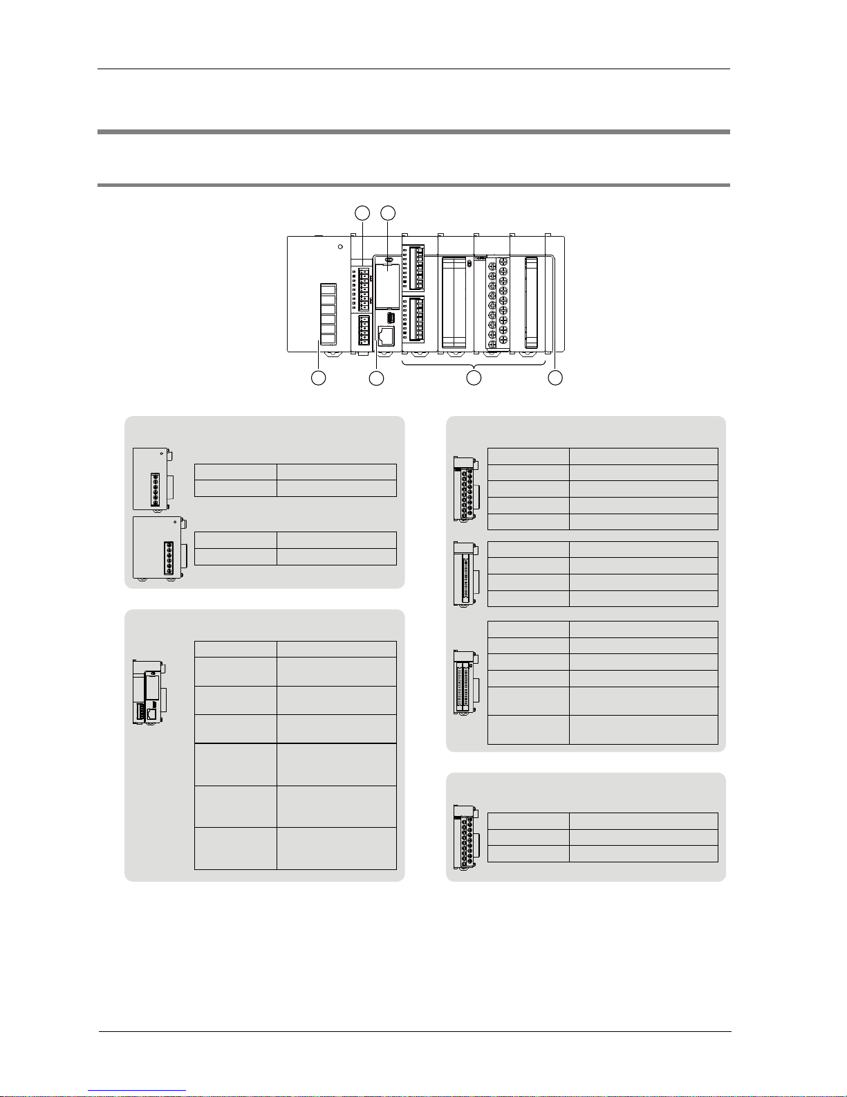
1.1.1 Units
3241
5
6
③ Digital I/O Units
Model number
AFP7X16DW
Remarks
Input 16-point, 12 to 24VDC
AFP7Y16R
Output 16-point, Relay
AFP7Y16T
Output 16-point, Sink type
AFP7Y16P
Output 16-point , Source type
Model number
AFP7XY64D2T
Remarks
Input 32-point, 24V DC
Output 32-point, Sink type
AFP7X64D2
Input 64-point, 24V DC
AFP7Y64T
Output 64-point, Sink type
AFP7Y64P
Output 64-point , Source type
AFP7XY64D2P
Input 32-point, 24V DC
Output 32-point , Source type
Model number
AFP7X32D2
Remarks
Input 32-point, 24V DC
AFP7Y32T
Output 32-point, Sink type
AFP7Y32P
Output 32-point , Source type
③ Analog I/O Units
Model number
AFP7AD4H
Remarks
Input 4ch
AFP7DA4H
Output 4ch
① Power Supply Unit
Model number
AFP7PSA1
Remarks
100 to 240V AC, 24W
Model number
AFP7PSA2
Remarks
100 to 240V AC, 43W
② CPU Unit
Model number
AFP7CPS41E
Remarks
196k steps
With Ethernet functi on
120k steps
With Ethernet functi on
120k steps
Without Ethernet fu nc tion
196k steps
With Ethernet function
With Encryption function
120k steps
With Ethernet function
With Encryption function
120k steps
Without Ethernet fu nc tion
With Encryption function
AFP7CPS31E
AFP7CPS31
AFP7CPS41ES
AFP7CPS31ES
AFP7CPS31S
Phone: 800.894.0412 - Fax: 888.723.4773 - Web: www.clrwtr.com - Email: info@clrwtr.com
1.1 System Configuration
1-3
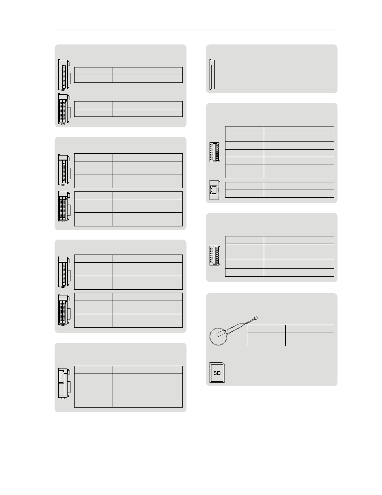
③ Positioning Unit
Model number
AFP7PP02T
Remarks
2-axis, Pulse train, 500kpps
Open collector output
AFP7PP02L
2-axis, Pulse train, 4Mpps
Line driver output
Model number
AFP7PP04T
Remarks
4-axis, Pulse train, 500kpps
Open collector output
AFP7PP04L
4-axis, Pulse train, 4Mpps
Line driver output
Model number
AFP7PG02T
Remarks
2-axis, Pulse train, 500kpps
Open collector output
AFP7PG02L
2-axis, Pulse train, 4Mpps
Line driver output
Model number
AFP7PG04T
Remarks
4-axis, Pulse train, 500kpps
Open collector output
AFP7PG04L
4-axis, Pulse train, 4Mpps
Line driver output
⑤ Add-on Cassette (Optional)
● Communication Cassette
Model number
AFP7CCS1
Remarks
Model number
Remarks
RS-232C × 1ch
AFP7CCS2
RS-232C × 2ch
AFP7CCM1
RS-422 / RS-485 × 1ch
AFP7CCM2
RS-422 / RS-485 × 2ch
AFP7CCS1M1
RS-232C × 1ch
RS-422 / RS-485 × 1ch
Model number
AFP7CCET1
Remarks
Ethernet × 1ch
⑤ Add-on Cassette (Optional)
● Function Cassette
④ End Unit
⑥ CPU Unit Attachment Options
● Backup battery
● SD memory card
Model number
AFPX-BATT
Remarks
Only used for the
clock / calendar
Commercially available products
For project backup and SD memory
card operation
③ High-speed Counter Unit
Model number
AFP7HSC2T
Remarks
2ch
Model number
AFP7HSC4T
Remarks
4ch
③ Serial Communication Unit
Model number
AFP7NSC
Remarks
Selectable combination
of two interfaces from
AFP7CCS1、AFP7CCS2
AFP7CCM1、AFP7CCM2
AFP7CCS1M1
Connect to the end of system
Attaches to CPUunit.
AFP7FCAD2
Analog input x 2ch
AFP7FCA21
Analog input x 2ch
AFP7FCTC2
Thermocouple input x 2ch
Analog output x 1ch
③ Pulse Output Unit
Phone: 800.894.0412 - Fax: 888.723.4773 - Web: www.clrwtr.com - Email: info@clrwtr.com
1-4
Overview
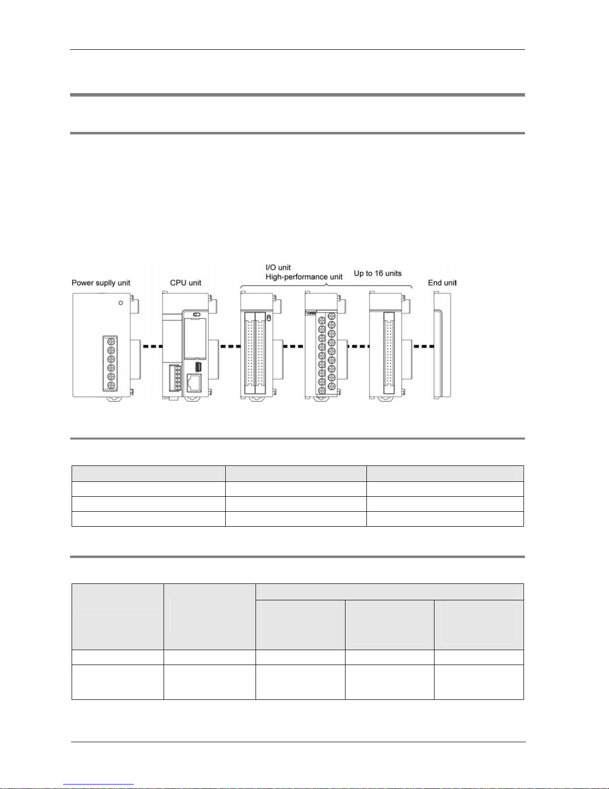
1.2 Restrictions on Combinations of Units
1.2.1 Common Restrictions on Each Unit
You can use FP7 series combining the CPU unit with optional input/output units and
intelligent units.
Up to 16 input/output units and intelligent units can be connected.
Make sure to connect an end unit to the end of the system.
You can either connect a power supply unit for system driving power, or directly supply
power from an external 24 V DC power supply to the CPU unit. See “1.3 Selection of Power
Supply and
Restrictions on Combi
nation“ for restrictions on combination.
1.2.2 Restrictions on the Number of Installed Units
There are following restrictions depending on units to be used.
Unit type Number of installed units Remarks
Power Supply Unit, CPU Unit Max. 1 unit
Serial Communication Unit Max. 8 units
Other units Max. 16 units
1.2.3 Restrictions on the Combination of Extension Cassettes
There are following restrictions depending on units and cassettes to be used.
Attachable add-on cassettes
Unit type
Number of
attachable
cassettes
Communication
cassette
AFP7CCS*
AFP7CCM*
Communication
cassette
AFP7CCET
Application
cassette
AFP7FC*
CPU Unit Max. 1 unit
Attachable Attachable Attachable
Serial
Communication
Unit
Max. 2 units per
unit
Attachable Not attachable Not attachable
Phone: 800.894.0412 - Fax: 888.723.4773 - Web: www.clrwtr.com - Email: info@clrwtr.com

1.2 Restrictions on Combinations of Units
1-5
1.2.4 Restrictions on Communication Functions to be Used
There are the following restrictions on functions to be used when using the SCU or ET-LAN
that is built in the CPU unit, or the serial communication unit (SCU).
Function to be used Restrictions
PLC link function
Up to two communication ports can be used. For using two ports, allocate
different link areas to them.
SCU built-in the CPU unit (COM.1 port)
Serial communication unit (COM.1 port)
MEWTOCOL-COM master
MODBUS-RTU master
A maximum of 16 communication ports and the number of connections in
combination can be used simultaneously.
SCU built-in the CPU unit (COM.1 port to COM. 2 port)
Serial communication unit (COM.1 port to COM.4 port)
ET-LAN built-in the CPU unit (User connections 1 to 16)
MEWTOCOL-COM slave
MEWTOCOL7-COM slave
MODBUS-RTU slave
A maximum of 15 communication ports and the number of connections in
combination can be used simultaneously.
SCU built-in the CPU unit (COM.1 port to COM. 2 port)
Serial communication unit (COM.1 port to COM.4 port)
ET-LAN built-in the CPU unit
(System connections 1 to 4 / User connections 1 to 16)
General-purpose
communication
There is no restriction.
1.2.5 Unit to be Used and Applicable Versions of CPU Unit and FPWIN GR 7
For using the unit, the following versions of CPU unit and FPWINGR7 are required.
Applicable versions
Unit type
CPU unit FPWINGR7
Remarks
FP7 High-speed Counter Unit Ver.1.2 or later Ver.1.2 or later (Note 1)
FP7 Serial Communication Unit Ver.1.2 or later Ver.1.3 or later
FP7 Communication Cassette
(Ethernet type)
Ver.1.3 or later Ver.1.0 or later (Note 2)
FP7 Analog I/O Cassette, Analog
Input Cassette, Thermocouple Input
Cassette
Ver.2.0 or later Ver.2.0 or later
FP7 Pulse Output Unit Ver.2.0 or later Ver.2.0 or later
(Note 1) For using the high-speed counter unit and the positioning unit in combination, and for using the interrupt
function with the high-speed counter unit, the positioning unit Ver.1.1 or later is required.
(Note 2) Configurator WD should be Ver.1.7 or later.
Phone: 800.894.0412 - Fax: 888.723.4773 - Web: www.clrwtr.com - Email: info@clrwtr.com
1-6
Overview
1.3 Selection of Power Supply and Restrictions on
Combination
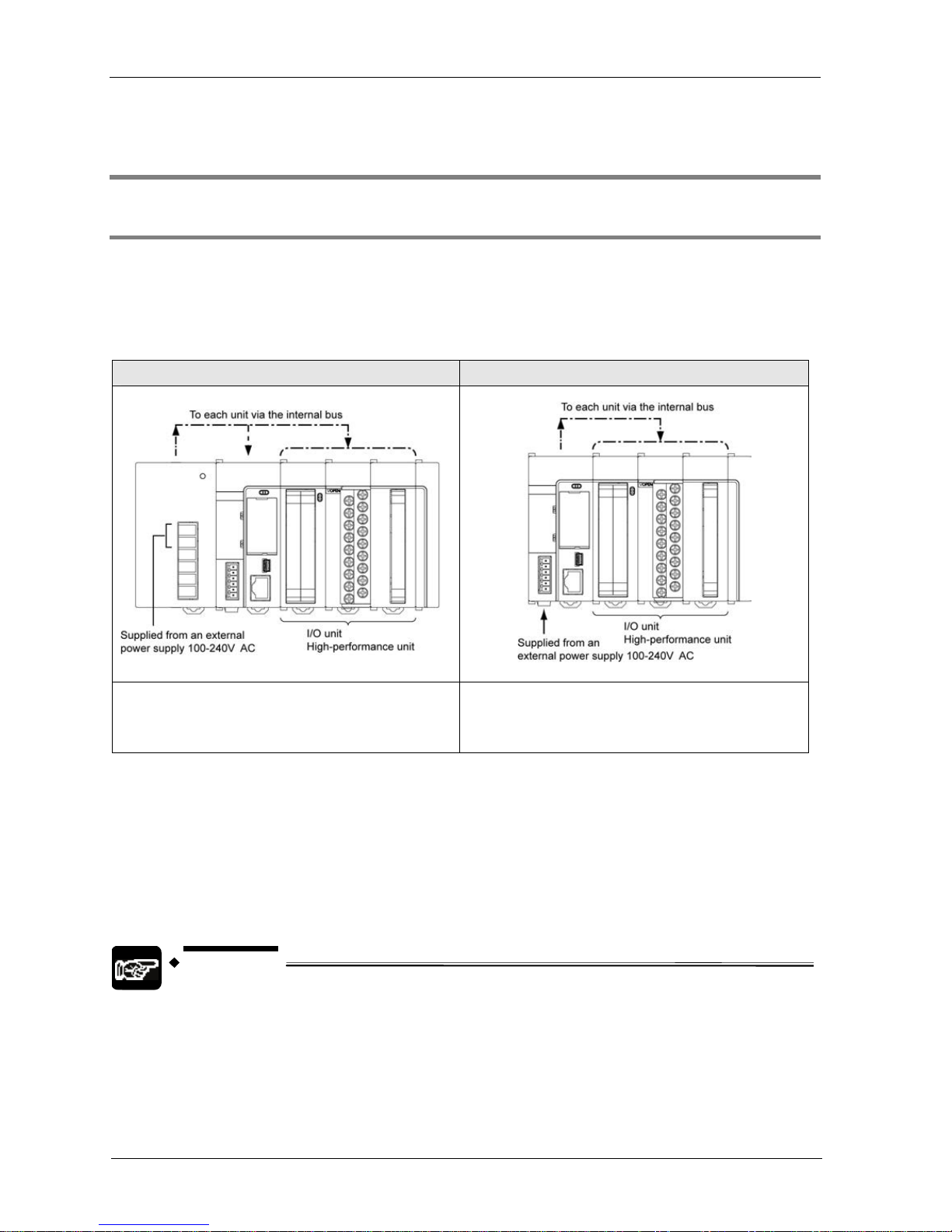
1.3.1 Power Supply for Internal Circuit
Restrictions on combination of power supply for internal circuit and units
Power for internal circuit is supplied from a power supply terminal of the power supply unit or
the CPU unit.
Select units within the respective restrictions indicated below.
When a power supply unit is used When no power supply unit is used
Select units so that the sum of internal current
consumptions of connected input/output units and
intelligent units does not exceed the capacity of the
power supply unit.
Select units so that the sum of internal current
consumptions of connected input/output units and
intelligent units does not exceed Max. 2 A.
Selection of a 24V DC power supply
Select a power supply larger than the capacity of the units. In the minimum configuration,
select a power supply of 24 W or larger.
In order to protect the unit against abnormal voltage from the power supply line, the power
supply should be an insulated type, and should be enclosed within a protective circuit.
If using a power supply device without an internal protective circuit, always make sure power
is supplied to the unit through a protective element such as a fuse.
NOTE
When a power supply unit is used, do not connect a DC power supply to the CPU unit.
Phone: 800.894.0412 - Fax: 888.723.4773 - Web: www.clrwtr.com - Email: info@clrwtr.com

1.3 Selection of Power Supply and Restrictions on Combination
1-7
Output current of power supply units (24V)
Product name Model number
Rated output
current (mA)
100 to 240V AC, 24W AFP7PSA1 1,000
Power Supply Unit
100 to 240V AC, 43W AFP7PSA2 1,800
Unit’s current consumption table (24V)
Product name Model number
Current
consumption (mA)
196k steps, Built-in Ethernet function
AFP7CPS4E
AFP7CPS41E
AFP7CPS41ES
200 mA or less
120k steps, Built-in Ethernet function
AFP7CPS3E
AFP7CPS31E
AFP7CPS31ES
200 mA or less
CPU Unit
120k steps, No Ethernet function
AFP7CPS3
AFP7CPS31
AFP7CPS31S
200 mA or less
RS-232C x 1ch AFP7CCS1 35 mA or less
RS-232C x 2ch AFP7CCS2 60 mA or less
RS-422 / 485 x 1ch AFP7CCM1 60 mA or less
RS-422 / 485 x 2h AFP7CCM2 90 mA or less
RS-232C x 1ch
RS-485 x 1ch
AFP7CCS1M1 70 mA or less
Add-on Cassette
(Communication
Cassette)
(Note 1) (Note 2)
When attaching to
CPU unit
Ethernet AFP7CCET1 35 mA or less
Analog I/O cassette AFP7FCA21 75 mA or less
Analog input cassette
AFP7FCAD2 40 mA or less
Add-on Cassette
(Function Cassette)
Thermocouple input cassette
AFP7FCTC2 45 mA or less
16-point terminal block, 5 to 24 V DC AFP7X16DW 25 mA or less
32-point MIL connector, 24V DC AFP7X32D2 30 mA or less
Input
Unit
DC Input
64-point MIL connector, 24V DC AFP7X64D2 35 mA or less
Relay
output
16-point terminal block AFP7Y16R 180 mA or less
16-point terminal block, sink type AFP7Y16T 35 mA or less
32-point MIL connector, sink type AFP7Y32T 50 mA or less
64-point MIL connector, sink type AFP7Y64T 75 mA or less
16-point terminal block, source type AFP7Y16P 35 mA or less
32-point MIL connector, source type AFP7Y32P 50 mA or less
Output
Unit
Transistor
output
64-point MIL connector, source type AFP7Y64P 75 mA or less
Input 32-point / output 32-point MIL
connector, sink type
AFP7XY64D2T 55 mA or less
I/O mixed unit
Input 32-point / output 32-point MIL
connector, source type
AFP7XY64D2P 55 mA or less
(Continued on the next page)
Phone: 800.894.0412 - Fax: 888.723.4773 - Web: www.clrwtr.com - Email: info@clrwtr.com

1-8
Overview
Product name Model number
Current
consumption (mA)
Analog Input Unit 4ch AFP7AD4H 100 mA or less
Analog Output Unit 4ch AFP7DA4H 250 mA or less
2-ch type
AFP7HSC2T 65 mA or less
High-speed Counter
Unit
4-ch type AFP7HSC4T 65 mA or less
2-axis, open collector output AFP7PG02T 65 mA or less
4-axis, open collector output
AFP7PG04T 65 mA or less
2-axis, line driver output
AFP7PG02L 65 mA or less
Pulse Output Unit
4-axis, line driver output
AFP7PG04L 65 mA or less
2-axis, open collector output AFP7PP02T 120 mA or less
4-axis, open collector output AFP7PP04T 120 mA or less
2-axis, line driver output AFP7PP02L 120 mA or less
Positioning Unit
4-axis, line driver output AFP7PP04L 120 mA or less
Serial Communication Unit AFP7NSC
50 mA 以下
RS-232C x 1ch AFP7CCS1
20 mA 以下
RS-232C x 2ch AFP7CCS2
40 mA 以下
RS-422 / 485 x 1ch AFP7CCM1
30 mA 以下
RS-422 / 485 x 2h AFP7CCM2
60 mA 以下
Extension Cassette
(Communication
Cassette) (Note 1)
(Note 2)
When attaching to
Serial
Communication Unit
RS-232C x 1ch
RS-485 x 1ch
AFP7CCS1M1
50 mA 以下
PHLS master unit AFP7RMTM 85 mA or less
Programmable display GT series (5V DC type) (Note 3) - 100 mA or less
(Note 1) Power consumption indicated under "Add-on Cassette" refers to the current consumption increment of the
CPU unit following addition of the relevant cassette.
(Note 2) The consumption current of add-on cassette (communication cassette) varies according to the unit to which
the cassette is attached (CPU unit or serial communication unit).
(Note 3) Power consumption indicated under "Display" refers to the current consumption increment of the CPU unit
following connection of a GT series display (5V power supply type) to the GT power supply terminal of the CPU
unit. For GT series displays (24V power supply type), please see their respective hardware specifications.
Phone: 800.894.0412 - Fax: 888.723.4773 - Web: www.clrwtr.com - Email: info@clrwtr.com

1.3 Selection of Power Supply and Restrictions on Combination
1-9
1.3.2 Power Supply for External Circuit
The 24 VDC power supply used as the input power supply of the input units and the output
circuit driving power of the output units are supplied from the external terminal of each unit.
Unit’s current consumption table (24V)
Product name Model name
Current
consumption (mA)
16-point terminal block, 5 to 24 V DC
AFP7X16DW 6 mA per point
32-point MIL connector, 24V DC AFP7X32D2 2.7 mA per point
Input
Unit
(Note 1)
DC Input
64-point MIL connector, 24V DC AFP7X64D2 2.7 mA per point
Relay output 16-point terminal block AFP7Y16R -
16-point terminal block, sink type AFP7Y16T 70 mA or less
32-point MIL connector, sink type AFP7Y32T 110 mA or less
64-point MIL connector, sink type AFP7Y64T 140 mA or less
16-point terminal block, source type AFP7Y16P 70 mA or less
32-point MIL connector, source type AFP7Y32P 130 mA or less
Output
Unit
Transistor
output
64-point MIL connector, source type AFP7Y64P 180 mA or less
Input 32-point / output 32-point MIL connector, sink
type
AFP7XY64D2T
Input 2.7 mA per point
Output 70 mA
I/O mixed
unit
Inupt 32-point / output 32-point MIL connector, source
type
AFP7XY64D2P
Input 3.4 mA per point
Output 90 mA
(Note 1) Figures for input unit indicate current that flows into the internal circuit. Figures for other units indicate current
values required for driving the internal circuit. This value does not include the load current of the output unit.
(Note 2) For current consumption of a 24 V power supply used for the I/O circuits of high-speed counter unit, pulse
output unit and positioning unit, please see the User’s Manual of each unit.
Phone: 800.894.0412 - Fax: 888.723.4773 - Web: www.clrwtr.com - Email: info@clrwtr.com
1-10
Overview
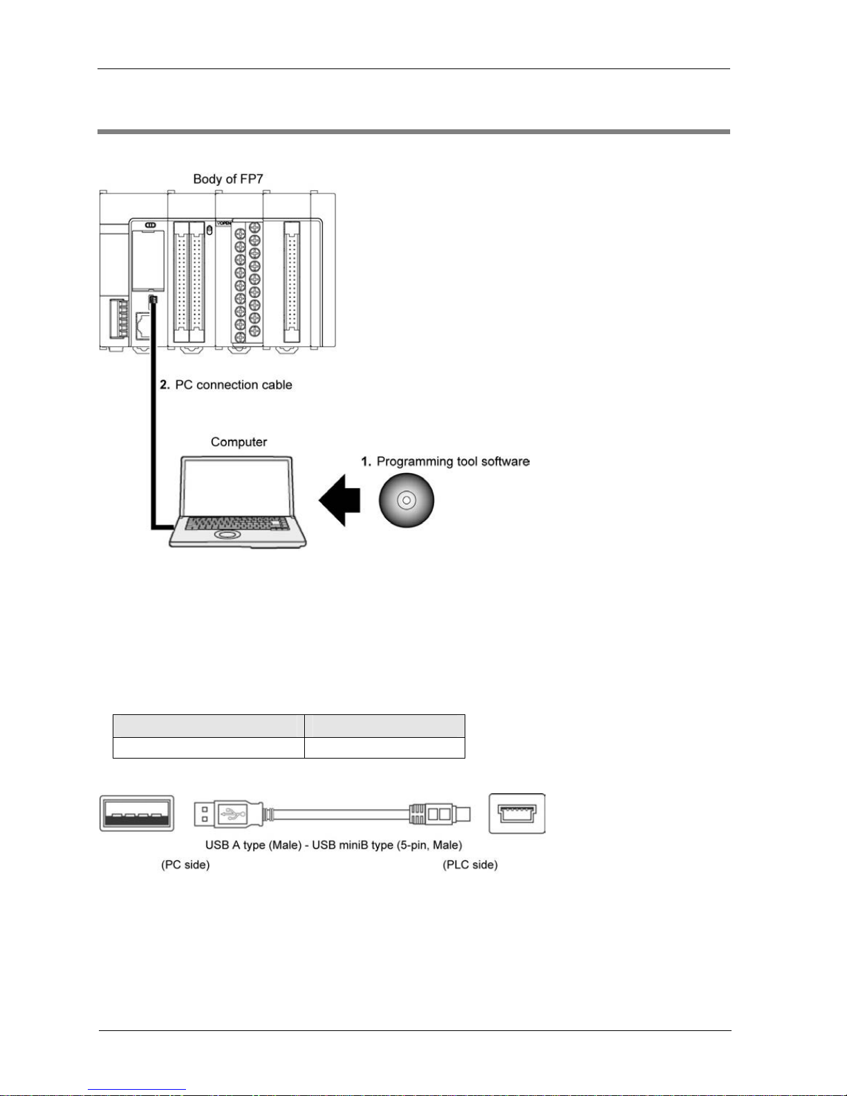
1.4 Programming Tools
Required tools
1. Tool software FPWIN GR7
Dedicated to the FP7 series
Used for program editing, debugging and documentation.
2. PC connection cable
Use a commercial cable.
Cable type Length
USB 2.0 cable (A:miniB) Max. 5m
Phone: 800.894.0412 - Fax: 888.723.4773 - Web: www.clrwtr.com - Email: info@clrwtr.com

2
Names and Functions of
Parts
Phone: 800.894.0412 - Fax: 888.723.4773 - Web: www.clrwtr.com - Email: info@clrwtr.com
2-2
Names and Functions of Parts
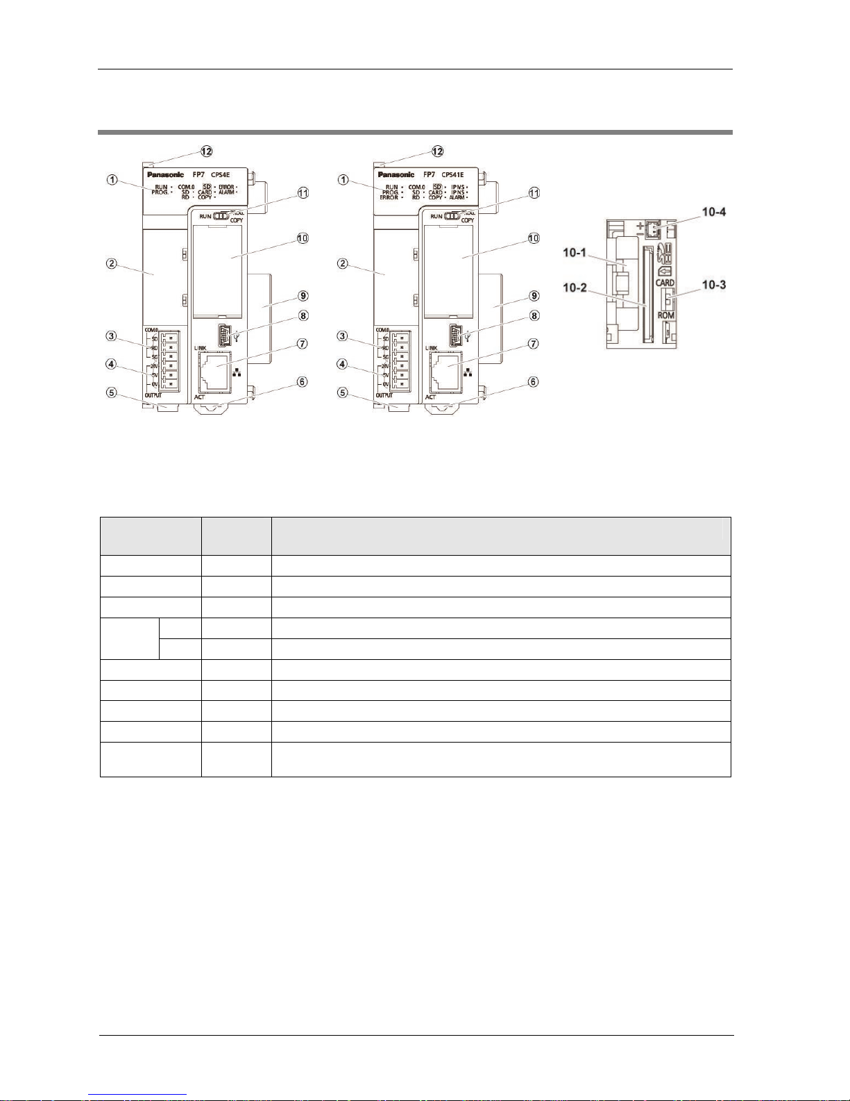
2.1 CPU Unit
CPS4E/CPS3E/CPS3
CPS41E/CPS31E/CPS31
CPS41ES/CPS31ES/CPS31S
Names and functions of parts
(1) Operation monitor LEDs
Body display
LED
color
Contents
- Blue Turns on when the CPU unit power is ON.
RUN Green Turns on in the RUN mode. Blinks during forced input/output.
PROG. Green Turns on in the PROG. mode.
SD Green Turns on while sending data from the COM.0 port.
COM.0
RD Green Turns on while receiving data from the COM.0 port.
SD Green Turns on while accessing the SD memory card.
CARD Green Turns on while operation by the SD memory card is selected.
COPY Green Turns on during the COPY operation.
ERROR Red Turns on when an error has been detected through self-diagnosis.
ALARM Red
Turns on if a hardware error occurs, or operation slows because of the program,
and the watchdog timer is activated.
Note) The layout of the operation monitor LEDs in Ver.1 of the CPU unit is different from that in Ver.2.
(2) Add-on cassette (Optional)
Attach an optional Add-on Cassette (Communication Cassette or Function Cassette).
(3) COM0 port terminal
3-wire RS-232C port
(4) GT power supply terminal
For our programmable display "GT series", either 5V DC or 24V DC can be used.
Phone: 800.894.0412 - Fax: 888.723.4773 - Web: www.clrwtr.com - Email: info@clrwtr.com

2.1 CPU Unit
2-3
(5) Power supply connector
Connected with an external power supply (24V DC); When a power supply unit is used, do not
connect this.
(6) DIN hook
Used for fixation on the DIN rail.
(7) LAN port (CPS4E、CPS41E、CPS41ES、CPS3E、CPS31E、CPS31ES)
Port for connection to Ethernet LAN
(8) USB port
Connected to a PC using the tool software
(9) Unit connectors
Connected to the internal circuit of I/O units and intelligent units
(10) CF card cover
Number Name Functions
10-1 Battery holder Attach a battery.
10-2 SD memory card slot Insert an SD memory card.
10-3 Card operation switch
Select between ROM operation or SD operation. By selecting SD
operation, provisional operation from the SD memory card
becomes possible.
10-4 Power supply connector Connected to a power supply connector
(11) Mode switch
Switch position Operation Mode
RUN (left) Set to the RUN mode. The program is executed and operation begins.
PROG. (middle) Set to the PROGRAM mode.
COPY (right, momentary)
When the switch is set to COPY, a project stored in the internal RAM /
ROM1 is transmitted to ROM2 as a backup project.
(Note) Whether the switch is set to RUN or PROG., the mode can be switched through remote operation from the
programming tool. When power is turned on again, it operates in the mode set on the switch.
(12) Fixing hook
Used for fixing a power supply unit to the CPU unit.
Phone: 800.894.0412 - Fax: 888.723.4773 - Web: www.clrwtr.com - Email: info@clrwtr.com

2-4
Names and Functions of Parts
2.2 Power Supply Unit
Names and functions of parts
(1) POWER LED (blue)
Turns on when power supply is turned on.
(2) Power supply terminals
Terminal block for power supply wiring. A solderless terminal for M3 can be used.
(3) Earth terminals
The unit should be grounded at a grounding resistance of 100 Ω or less to prevent noise and
electric shock.
(4) Alarm contact output terminal
Closed when power supply is ON. If the watchdog timer is operated due to a hardware error
or a program error, turning the relay contact into an open status.
(5) DIN rail attachment lever
Used for fixation on the DIN rail.
Phone: 800.894.0412 - Fax: 888.723.4773 - Web: www.clrwtr.com - Email: info@clrwtr.com

3
I/O Number Allocation
Phone: 800.894.0412 - Fax: 888.723.4773 - Web: www.clrwtr.com - Email: info@clrwtr.com
3-2
I/O Number Allocation
3.1 Basics of I/O Allocation
3.1.1 How to Count the I/O Numbers
Counting and expression of the I/O numbers
Since I/O numbers are handled in units of 16 points, they are expressed as a combination of a
device type code and the lowest-digit of a decimal or hexadecimal number.
E.g. In the case of an external input, X0 to X9 and XA to XF are used.
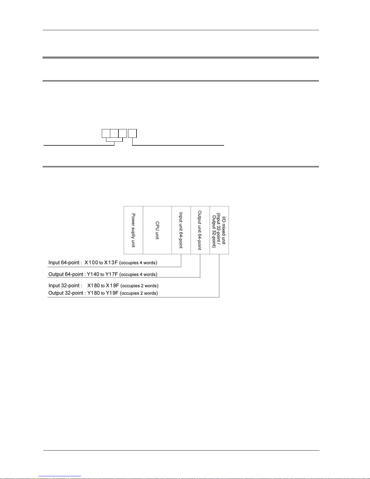
3.1.2 Concept of I/O Number Allocation
Examples of I/O Number Allocation
I/O numbers are determined by the status of unit attachment and the occupied I/O points
allocated to respective units.
Starting word numbers of input/output units and intelligent units
By default, the starting word number for the unit attached next to the CPU unit is set at "10",
and the I/O numbers start with X100 or Y100.
The starting word number for each unit can be freely changed in the "FP7 Configuration"
menu of the tool software FPWIN GR7.
How to count I/O numbers for units that have both inputs and outputs
In the case of a unit that has both inputs and outputs (e.g. mixed input/output units, intelligent
units), input numbers and output numbers start with the same value.
E.g. If input numbers for a mixed input/output unit are X100 to X11F, the unit's output
numbers are set at Y100 to Y11F.
I/O numbers allocated to the CPU unit
A fixed area is allocated to the COM port and the ET-LAN port.
1 2 7 F
<Decimal>
0, 1, 2, 3 ..... 9
<Hexadecimal>
0, 1, 2, 3 ..... 9, A, B ...F
Phone: 800.894.0412 - Fax: 888.723.4773 - Web: www.clrwtr.com - Email: info@clrwtr.com

3.1 Basics of I/O Allocation
3-3
3.1.3 Occupied I/O Points for Each Unit
List of occupied words and I/O points by unit
Occupied words
(occupied I/O points)
Unit Type Model number
Input Output
SCU built-in CPU Unit Common
2 words (32 points)
Fixed to WX0-WX1
2 words (32 points)
Fixed to WY0-WY1
Communication
Cassette
(Ethernet type)
AFP7CCET1
4 words (64 points)
Fixed to WX0-WX3
2 words (32 points)
Fixed to WY0-WY1
Analog I/O Cassette AFP7FCA21
1 word (16 points)
WY2
Analog Input Cassette AFP7FCAD2 -
Thermocouple Cassette AFP7FCTC2
2 words (32 points)
WX2 to WX3
-
System reserved area Common
Fixed to WX2 WX6
Fixed to WY2 -
WY6
CPU Unit
ET-LAN built-in CPU
Unit
AFP7CPS4*E*
AFP7CPS3*E*
3 words (48 points)
Fixed to WX7-WX9
3 words (48 points)
Fixed to WY7-WY9
Input unit 16 points AFP7X16DW 1 word (16 points)
Input unit 32 points AFP7X32D2 2 word (32 points)
Input unit 64 points AFP7X64D2 4 word (64 points)
Output unit 16 points
AFP7Y16R
AFP7Y16T
AFP7Y16P
1 word (16 points)
Output unit 32 points
AFP7Y32T
AFP7Y32P
2 word (32 points)
Output unit 64 points
AFP7Y64T
AFP7Y64P
4 word (64 points)
Input/Output
Units
Mixed input/output units
Input 32 points / Output
32 points
AFP7XY64D2T
AFP7XY64D2P
2 word (32 points) 2 word (32 points)
Analog Input Unit AFP7AD4H 8 word (128 points) 4 word (64 points)
Analog Output Unit AFP7DA4H 4 word (64 points) 8 word (128 points)
AFP7HSC2T
High-speed Counter
Unit
AFP7HSC4T
8 word (128 points) 4 word (64 point)
AFP7PG02T,
AFP7PG02L
2 word (32 points) 2 word (32 points)
Pulse Output Unit
AFP7PG04T,
AFP7PG04L
4 words (64 points) 4 words (64 points)
Positioning Unit
AFP7PP02T
AFP7PP02L
AFP7PP04T
AFP7PP04L
12 word
(196 points)
12 word
(196 points)
Serial Communication
Unit
AFP7NSC 2 words (32 points) 2 words (32 points)
Intelligent Unit
PHLS master unit AFP7PHLSM
63 word
(1,008 points)
63 word
(1,008 points)
(Note 1) Input/output contacts of the CPU unit are allocated for the usage of communication functions of each
cassette. Regardless of use of such functions, input occupies 10 words (160 points, WX0 to WX9) and output
occupies 10 words (160 words, WY0 to WY 9). The starting numbers of I/O contacts of each unit including the
CPU unit can be changed by the setting of tool software.
(Note 2) As for the PHLS master unit, input occupies 63 words (1,008 points) and output occupies 63 words (1,008
points). The actual input/output points that can be used vary by the number of slave units that are connected,
with the maximum of 1,008 points.
Phone: 800.894.0412 - Fax: 888.723.4773 - Web: www.clrwtr.com - Email: info@clrwtr.com

3-4
I/O Number Allocation
3.2 Optional Allocation Using FPWIN GR7
3.2.1 Registration of a Unit to be Used and the Starting Word Number
Allocation method
The unit to be used and the starting I/O number are set in the following procedure.
PROCEDURE
1. From the menu bar, select "Option" "FP7 Configuration".
2. In the relevant field, select "I/O map".
The "I/O map" dialog box is displayed.
3. Select and double-click Slot No. 0.
The “Unit selection” dialog box is displayed.
4. Confirm the CPU unit to be used and press the [OK] button.
The CPU unit is registered in the I/O map. If the CPU unit is different, select
"Tool" "Convert PLC Type" from the menu bar and change the type.
Phone: 800.894.0412 - Fax: 888.723.4773 - Web: www.clrwtr.com - Email: info@clrwtr.com
3.2 Optional Allocation Using FPWIN GR7
3-5
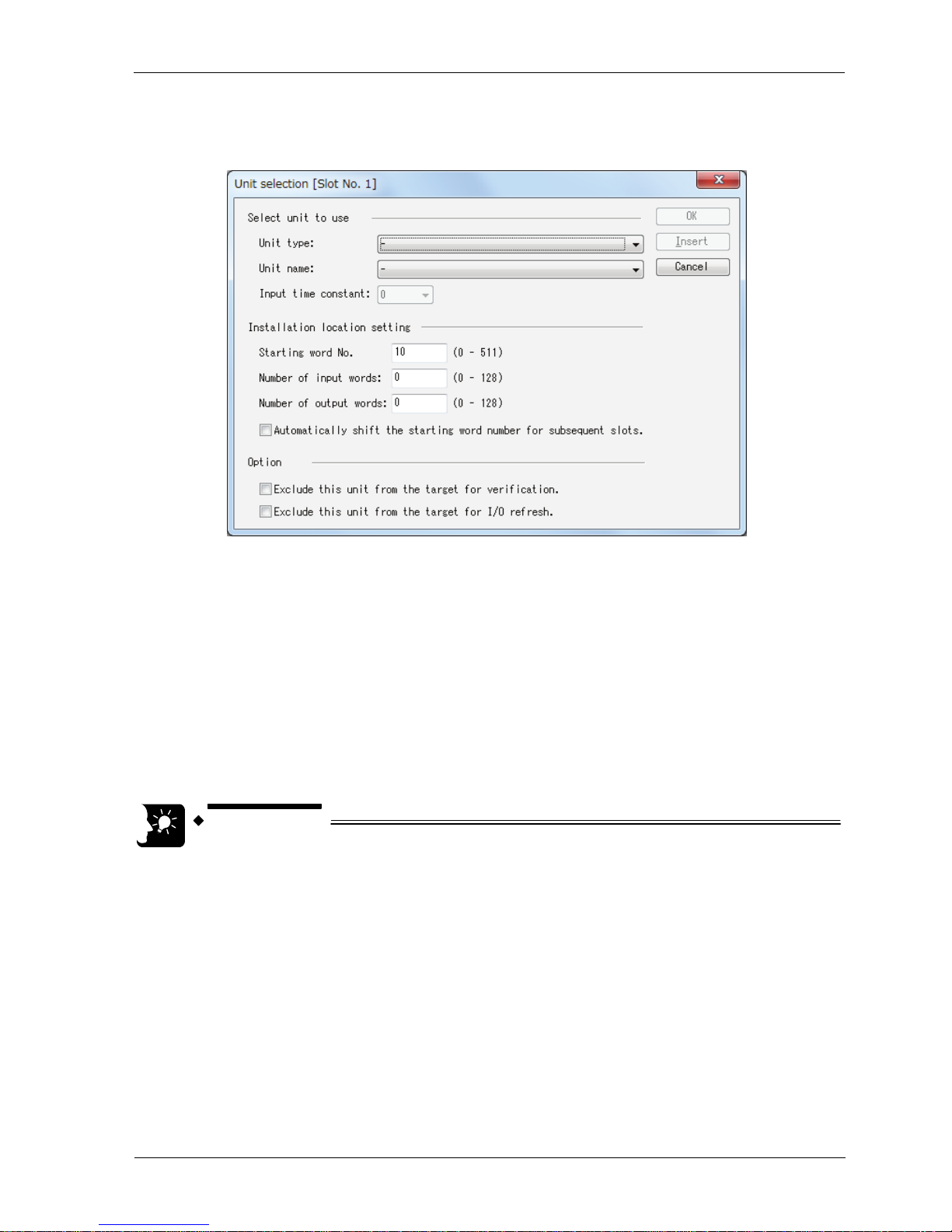
5. Select and double-click Slot No. 1.
The "Unit selection" dialog box is displayed.
6. In the unit type field, select a unit to be attached.
Subsequently, input words and output words are automatically entered.
7. As necessary, enter the starting word number and press the [OK] button.
The registered unit and the starting word number are included in the I/O map. A
number that combines the starting word number registered for each unit and 0 to
F becomes the starting I/O number.
6. Repeat registrations.
7. Press the [OK] button while the "FP7 configuration" dialog box is displayed.
KEY POINTS
The I/O map registered using FPWIN GR7 is downloaded into the CPU unit,
together with other project information. If a difference with the actual units
and/or attachment status is identified when power supply is turned on or
during operation, such a difference is reported as a self-diagnosis error.
If a starting word number is not entered, the system automatically enters
one.
Based on the starting word number allocated to each unit, I/O numbers are
allocated.
The starting number of I/O numbers allocated to the internal functions of
the CPU unit can be changed to another number from the word number 0.
Phone: 800.894.0412 - Fax: 888.723.4773 - Web: www.clrwtr.com - Email: info@clrwtr.com

3-6
I/O Number Allocation
3.2.2 Optional Settings in the “Unit Selection” Dialog Box
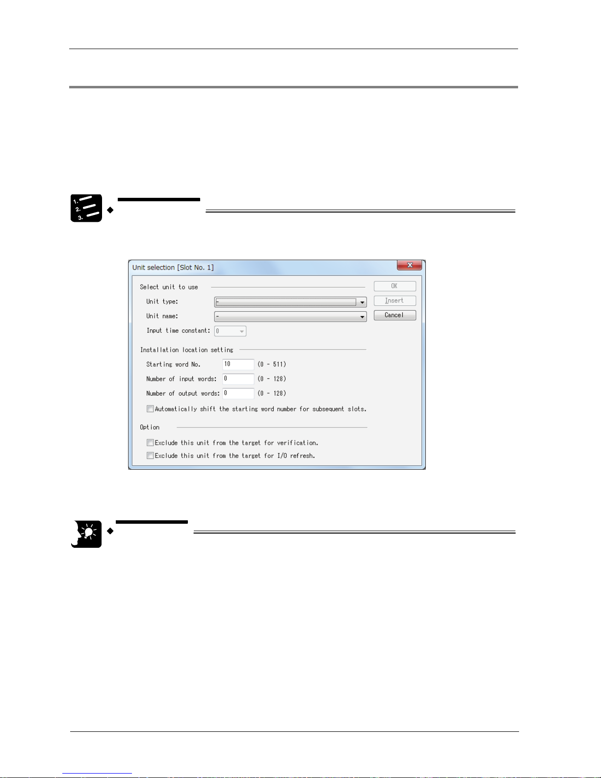
Input time constants
Input time constants for an input unit or a mixed input/output unit can be changed as
necessary. Select, and set for each unit, a desirable value from "No settings", 0.1, 0.5, 1.0,
5.0, 10.0, 20.0 or 70.0 ms. The selected time constants are added to the hardware-specific
response time of each unit.
For details, please see the "FP7 Digital Input/Output Unit Users Manual".
Exclude this unit from the scope of verification.
In general, this check box should be turned off.
If you want to exclude this unit from the scope of verification error temporarily for unit
replacement or adjustment, turn on this check box.
Exclude this unit from the scope of I/O refresh.
In general, this check box should be turned off. Input/output processing is performed at the
timing of I/O refresh in a normal scan.
By using operation devices "Direct input IN " or "Direct output OT", it becomes possible to
directly perform input/output processing during operation, independent of normal I/O refresh.
When this operation device is used, turn on the check box "Exclude this unit from the scope
of I/O refresh".
By turning this check box on, all inputs and outputs of registered units are excluded from the
scope of I/O refresh.
Phone: 800.894.0412 - Fax: 888.723.4773 - Web: www.clrwtr.com - Email: info@clrwtr.com

3.3 Mount Allocation Using FPWIN GR7
3-7
3.3 Mount Allocation Using FPWIN GR7
3.3.1 Mount Registration of a Unit to be Used and the Starting Word Number
What is mount registration?
If all units to be used are physically at hand, you can connect FPWIN GR7 online to the FP7
CPU unit, read the actual mount status, and complete registration.
Allocation method
Mount registration of the unit to be used and the initial I/O number are set in the following
procedure.
PROCEDURE
1. From the menu bar, select "Online" "Online Editing".
The screen is switched to the “Online Editing” mode.
2. Select "Option" "FP7 Configuration".
3. In the relevant field, select "I/O Map".
The "I/O Map" dialog box is displayed.
4. Press the [Mount Registration] button.
The mount status is read, and the read I/O map is registered in the CPU unit.
KEY POINTS
Following the mount registration operation, the system automatically reads
the unit attachment status, formulates an I/O map, and enters the initial
word number.
The I/O map that has been mount-registered using FPWIN GR7 is registered
into the CPU unit, together with other project information. If a difference
with the actual units and/or attachment status is identified when power
supply is turned on or during operation, such a difference is reported as a
self-diagnosis error.
If a starting word number is not entered, the system automatically enters
one.
Based on the starting word number allocated to each unit, I/O numbers are
allocated.
Phone: 800.894.0412 - Fax: 888.723.4773 - Web: www.clrwtr.com - Email: info@clrwtr.com
3-8
I/O Number Allocation
3.3.2 Changing the Starting Word Number
When you want to change the starting word number following mount registration, please take
the following procedure.
Allocation method
Changing the starting word number following mount registration should be performed in the
following procedure. In the following procedure, it is assumed that an I/O map is already
displayed.
PROCEDURE
1. On the "I/O Map", double click a unit for which the starting word number
should be changed.
2. Enter a desired starting word number and press the [OK] button.
The changed number is registered in the I/O map.
KEY POINTS
Once you change the starting word number using FPWIN GR7, the I/O map
is changed from the initial status following mount registration. It is
necessary to edit the I/O map online, or to download the project once again.
Phone: 800.894.0412 - Fax: 888.723.4773 - Web: www.clrwtr.com - Email: info@clrwtr.com
 Loading...