

Panasonic A-18-F, A-27-F, A-28-F, A-37-F-6-0, A-37-FW User Manual
...
User Manual of Network Camera
Network Camera
User Manual
0

Network Camera User Manual
A-17-F
1.3MPx dome camera, 3.6mm
A-17-F12
1.3MPx dome camera, 12mm
A-37-F
3.0MPx dome camera, 3.6mm
A-37-FW
3.0MPx dome camera, 2.8mm
A-37-F6.0
3.0MPx dome camera, 6mm
A-18-F
1.3MPx bullet camera, 6mm
A-38-F
3.0MPx bullet camera, 6mm
A-38-F4.0
3.0MPx bullet camera, 4mm
A-47-F
4.0MPx mini dome, 4mm
A-47-F2.8
4.0MPx mini dome, 2.8mm
A-28-F
2.0MPx bullet camera, 6mm
A-27-F
2.0MPx dome camera, 2.8mm
User Manual
About this Manual
This Manual is applicable to the following Network Camera.
The Manual includes instructions for using and managing the product. Pictures, charts,
images and all other information hereinafter are for description and explanation only.
The information contained in the Manual is subject to change, without notice, due to
firmware updates or other reasons. Please find the latest version in the company
website.
Please use this user manual under the guidance of professionals.
Legal Disclaimer
TO THE MAXIMUM EXTENT PERMITTED BY APPLICABLE LAW, THE
PRODUCT DESCRIBED, WITH ITS HARDWARE, SOFTWARE AND
FIRMWARE, IS PROVIDED “AS IS”, WITH ALL FAULTS AND ERRORS, AND
OUR COMPANY MAKES NO WARRANTIES, EXPRESS OR IMPLIED,
INCLUDING WITHOUT LIMITATION, MERCHANTABILITY,
SATISFACTORY QUALITY, FITNESS FOR A PARTICULAR PURPOSE, AND
NON-INFRINGEMENT OF THIRD PARTY. IN NO EVENT WILL OUR
COMPANY, ITS DIRECTORS, OFFICERS, EMPLOYEES, OR AGENTS BE
LIABLE TO YOU FOR ANY SPECIAL, CONSEQUENTIAL, INCIDENTAL, OR
INDIRECT DAMAGES, INCLUDING, AMONG OTHERS, DAMAGES FOR
LOSS OF BUSINESS PROFITS, BUSINESS INTERRUPTION, OR LOSS OF
1

Network Camera User Manual
DATA OR DOCUMENTATION, IN CONNECTION WITH THE USE OF THIS
PRODUCT, EVEN IF OUR COMPANY HAS BEEN ADVISED OF THE
POSSIBILITY OF SUCH DAMAGES.
REGARDING TO THE PRODUCT WITH INTERNET ACCESS, THE USE OF
PRODUCT SHALL BE WHOLLY AT YOUR OWN RISKS. OUR COMPANY
SHALL NOT TAKE ANY RESPONSIBILITES FOR ABNORMAL OPERATION,
PRIVACY LEAKAGE OR OTHER DAMAGES RESULTING FROM CYBER
ATTACK, HACKER ATTACK, VIRUS INSPECTION, OR OTHER INTERNET
SECURITY RISKS; HOWEVER, OUR COMPANY WILL PROVIDE TIMELY
TECHNICAL SUPPORT IF REQUIRED.
SURVEILLANCE LAWS VARY BY JURISDICTION. PLEASE CHECK ALL
RELEVANT LAWS IN YOUR JURISDICTION BEFORE USING THIS PRODUCT
IN ORDER TO ENSURE THAT YOUR USE CONFORMS THE APPLICABLE
LAW. OUR COMPANY SHALL NOT BE LIABLE IN THE EVENT THAT THIS
PRODUCT IS USED WITH ILLEGITIMATE PURPOSES.
IN THE EVENT OF ANY CONFLICTS BETWEEN THIS MANUAL AND THE
APPLICABLE LAW, THE LATER PREVAILS.
Regulatory Information
FCC Information
FCC compliance: This equipment has been tested and found to comply with the
limits for a digital device, pursuant to part 15 of the FCC Rules. These limits are
designed to provide reasonable protection against harmful interference when the
equipment is operated in a commercial environment. This equipment generates, uses,
and can radiate radio frequency energy and, if not installed and used in accordance
with the instruction manual, may cause harmful interference to radio communications.
Operation of this equipment in a residential area is likely to cause harmful
interference in which case the user will be required to correct the interference at his
own expense.
FCC Conditions
2
Network Camera User Manual
This device complies with part 15 of the FCC Rules. Operation is subject to the
following two conditions:
1. This device may not cause harmful interference.
2. This device must accept any interference received, including interference that may
cause undesired operation.
EU Conformity Statement
This product and - if applicable - the supplied accessories too are
marked with "CE" and comply therefore with the applicable
harmonized European standards listed under the EMC Directive
2004/108/EC, the RoHS Directive 2011/65/EU.
2012/19/EU (WEEE directive): Products marked with this symbol
cannot be disposed of as unsorted municipal waste in the European
Union. For proper recycling, return this product to your local
supplier upon the purchase of equivalent new equipment, or dispose
of it at designated collection points. For more information see: www.recyclethis.info.
2006/66/EC (battery directive): This product contains a battery that
cannot be disposed of as unsorted municipal waste in the European
Union. See the product documentation for specific battery
information. The battery is marked with this symbol, which may
include lettering to indicate cadmium (Cd), lead (Pb), or mercury (Hg). For proper
recycling, return the battery to your supplier or to a designated collection point. For
more information see: www.recyclethis.info.
Industry Canada ICES-003 Compliance
This device meets the CAN ICES-3 (A)/NMB-3(A) standards requirements.
Safety Instruction
These instructions are intended to ensure that the user can use the product correctly to
avoid danger or property loss.
The precaution measure is divided into ‘Warnings’ and ‘Cautions’:
3
Network Camera User Manual
Warnings Follow these safeguards to
prevent serious injury or death.
Cautions Follow these precautions to
prevent potential injury or material
damage.
Warnings: Serious injury or death may be caused if any of these warnings are
neglected.
Cautions: Injury or equipment damage may be caused if any of these cautions are
neglected.
Warnings:
Please adopt the power adapter which can meet the safety extra low voltage
(SELV) standard. And source with 12 VDC or 24 VAC (depending on models)
according to the IEC60950-1 and Limited Power Source standard.
To reduce the risk of fire or electrical shock, do not expose this product to rain or
moisture.
This installation should be made by a qualified service person and should conform
to all the local codes.
Please install blackouts equipment into the power supply circuit for convenient
supply interruption.
Please make sure that the ceiling can support more than 50(N) Newton gravities if
the camera is fixed to the ceiling.
If the product does not work properly, please contact your dealer or the nearest
service center. Never attempt to disassemble the camera yourself. (We shall not
assume any responsibility for problems caused by unauthorized repair or
maintenance.)
Cautions:
4

Network Camera User Manual
Make sure the power supply voltage is correct before using the camera.
Do not drop the camera or subject it to physical shock.
Do not touch sensor modules with fingers. If cleaning is necessary, use a clean
cloth with a bit of ethanol and wipe it gently. If the camera will not be used for an
extended period of time, put on the lens cap to protect the sensor from dirt.
Do not aim the camera lens at the strong light such as sun or incandescent lamp.
The strong light can cause fatal damage to the camera.
The sensor may be burned out by a laser beam, so when any laser equipment is
being used, make sure that the surface of the sensor not be exposed to the laser
beam.
Do not place the camera in extremely hot, cold temperatures (the operating
temperature should be between -30°C to +60°C, or -40°C to +60°C if the camera
model supports heater), dusty or damp environment, and do not expose it to high
electromagnetic radiation.
To avoid heat accumulation, ensure there is good ventilation to the device.
Keep the camera away from water and any liquids.
While shipping, pack the camera in its original, or equivalent, packing materials.
Or packing the same texture.
Improper use or replacement of the battery may result in hazard of explosion.
Please use the manufacturer recommended battery type.
Notes:
For the camera supports IR, you are required to pay attention to the following
precautions to prevent IR reflection:
Dust or grease on the dome cover will cause IR reflection. Please do not remove
the dome cover film until the installation is finished. If there is dust or grease on
the dome cover, clean the dome cover with clean soft cloth and isopropyl alcohol.
Make certain the installation location does not have reflective surfaces of objects
too close to the camera. The IR light from the camera may reflect back into the
lens causing reflection.
The foam ring around the lens must be seated flush against the inner surface of
5

Network Camera User Manual
the bubble to isolate the lens from the IR LEDS. Fasten the dome cover to camera
body so that the foam ring and the dome cover are attached seamlessly.
6

Network Camera User Manual
Table of Contents
Chapter 1 System Requirement ........................................................................... 8
Chapter 2 Network Connection .......................................................................... 10
2.1 Setting the Network Camera over the LAN ...................................................... 10
2.1.1 Wiring over the LAN ....................................................................................................... 10
2.1.2 Activating the Camera .................................................................................................... 11
Chapter 3 Access to the Network Camera........................................................... 15
3.1 Accessing by Web Browsers ............................................................................ 15
Chapter 4 Live View .......................................................................................... 17
4.1 Live View Page ............................................................................................... 17
4.2 Starting Live View .......................................................................................... 17
4.3 Recording and Capturing Pictures Manually .................................................... 18
Chapter 5 Network Camera Configuration ........................................................ 19
5.1 Configuring Local Parameters ......................................................................... 19
5.2 Configure System Settings .............................................................................. 21
5.2.1 Configuring Basic Information ........................................................................................ 21
5.2.2 Configuring Time Settings ............................................................................................... 21
5.2.3 Configuring DST Settings ................................................................................................. 23
5.2.4 System Service ................................................................................................................ 24
5.2.5 Configuring RS232 Settings ............................................................................................. 24
5.3 Maintenance ................................................................................................. 25
5.3.1 Upgrade & Maintenance ................................................................................................. 25
5.3.2 Log .................................................................................................................................. 26
5.4 Security Settings ............................................................................................ 27
5.4.1 Authentication ................................................................................................................ 27
5.4.2 IP Address Filter .............................................................................................................. 28
5.4.3 Security Service............................................................................................................... 29
5.5 User Management ......................................................................................... 30
5.5.1 User Management .......................................................................................................... 30
5.5.2 Online Users .................................................................................................................... 34
Chapter 6 Network Settings ............................................................................... 35
6.1 Configuring Basic Settings .............................................................................. 35
6.1.1 Configuring TCP/IP Settings ............................................................................................ 35
6.1.2 Configuring DDNS Settings .............................................................................................. 36
6.1.3 Configuring Port Settings ................................................................................................ 38
6.1.4 Configuring NAT Settings ................................................................................................ 38
7

Network Camera User Manual
6.2 Configure Advanced Settings .......................................................................... 40
6.2.1 Configuring SNMP Settings ............................................................................................. 40
6.2.2 Configuring FTP Settings ................................................................................................. 41
6.2.3 Configuring Email Settings .............................................................................................. 43
6.2.4 Configuring HTTPS Settings ............................................................................................. 46
6.2.5 Configuring QoS Settings ................................................................................................ 47
6.2.6 Configuring 802.1X Settings ............................................................................................ 48
Chapter 7 Video/Audio Settings ......................................................................... 50
7.1 Configuring Video Settings ............................................................................. 50
7.2 Configuring Audio Settings ............................................................................. 53
7.3 Configuring ROI Encoding ............................................................................... 54
7.4 Display Info. on Stream .................................................................................. 55
Chapter 8 Image Settings .................................................................................. 55
8.1 Configuring Display Settings ........................................................................... 56
8.1.1 Day/Night Auto-Switch ................................................................................................... 56
8.1.2 Day/Night Scheduled-Switch .......................................................................................... 60
8.2 Configuring OSD Settings ................................................................................ 61
8.3 Configuring Privacy Mask ............................................................................... 62
Chapter 9 Event Settings ................................................................................... 63
9.1 Basic Events ................................................................................................... 63
9.1.1 Configuring Motion Detection ........................................................................................ 63
9.1.2 Configuring Video Tampering Alarm .............................................................................. 70
9.1.3 Configuring Alarm Input ................................................................................................. 71
9.1.4 Configuring Alarm Output .............................................................................................. 72
9.1.5 Handling Exception ......................................................................................................... 73
9.2 Smart Events .................................................................................................. 74
9.2.6 Configuring Intrusion Detection ..................................................................................... 74
9.2.7 Configuring Line Crossing Detection ............................................................................... 76
Chapter 10 Storage Settings ............................................................................. 78
10.1 Configuring Record Schedule .......................................................................... 78
10.2 Configuring Capture Schedule ......................................................................... 81
10.3 Configuring Net HDD ...................................................................................... 83
Chapter 11 Playback........................................................................................ 86
Appendix 1 Features of Different Cameras .................................................................. 88
Chapter 1 System Requirement
Operating System: Microsoft Windows XP SP1 and above version
8

Network Camera User Manual
CPU: 2.0 GHz or higher
RAM: 1G or higher
Display: 1024×768 resolution or higher
Web Browser: Internet Explorer 8.0 and above version, Apple Safari 5.0.2 and above
version, Mozilla Firefox 5.0 and above version and Google Chrome 18 and above
version.
9

User Manual of Network Camera
Chapter 2 Network Connection
Note:
You shall acknowledge that the use of the product with Internet access might be
under network security risks. For avoidance of any network attacks and
information leakage, please strengthen your own protection. If the product does
not work properly, please contact with your dealer or the nearest service center.
To ensure the network security of the network camera, we recommend you to
have the network camera assessed and maintained termly. You can contact us if
you need such service.
Before you start:
If you want to set the network camera via a LAN (Local Area Network), please
refer to Section 2.1 Setting the Network Camera over the LAN.
2.1 Setting the Network Camera over the LAN
Purpose:
To view and configure the camera via a LAN, you need to connect the network
camera in the same subnet with your computer, and install the Advidia Camera Finder
to search and change the IP of the network camera.
2.1.1 Wiring over the LAN
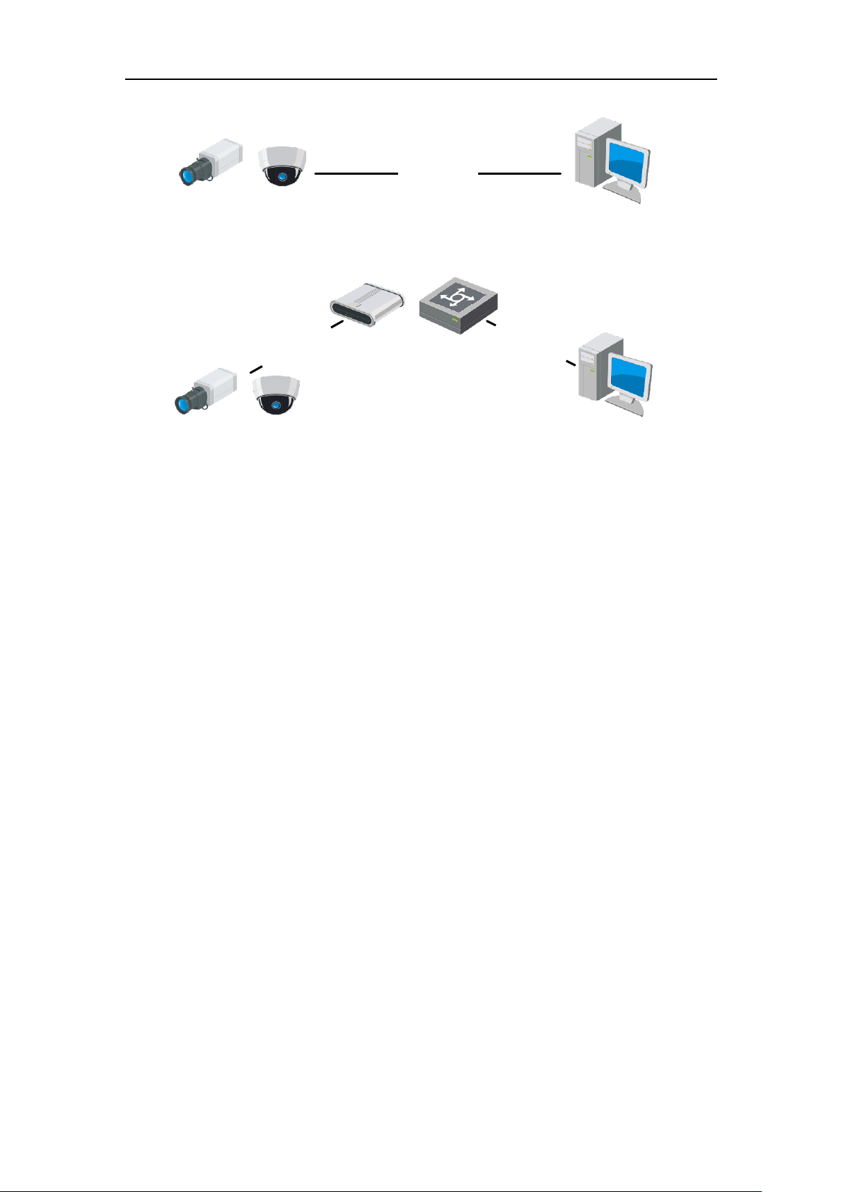
The following figures show the two ways of cable connection of a network camera
and a computer:
Purpose:
To test the network camera, you can directly connect the network camera to the
computer with a network cable as shown in Figure 2-1.
Refer to the Figure 2-2 to set network camera over the LAN via a switch or a
router.
10
Network Camera User Manual
Network Cable
or
Network Camera
Computer
Network Cable
Network Cable
or
or
Network Camera Computer
Figure 2-1 Connecting Directly
Figure 2-2 Connecting via a Switch or a Router
2.1.2 Activating the Camera
You are required to activate the camera first by setting a strong password for it before
you can use the camera.
Activation via Web Browser, or Advidia Camera Finder are both supported.
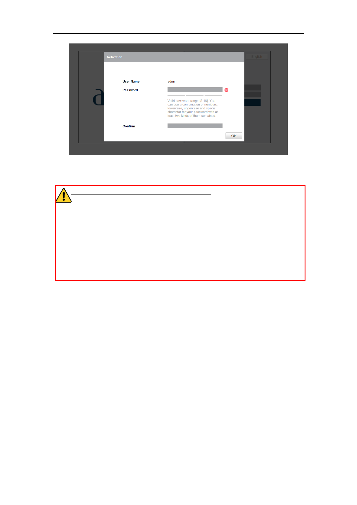
Activation via Web Browser
Steps:
1. Power on the camera, and connect the camera to the network.
2. Input the IP address into the address bar of the web browser, and click Enter to
enter the activation interface.
Notes:
The default IP address of the camera is 192.0.0.64.
11
Network Camera User Manual
Figure 2-3 Activation via Web Browser
3. Create a password and input the password into the password field.
STRONG PASSWORD RECOMMENDED–We highly recommend you
create a strong password of your own choosing (using a minimum of 8
characters, including at least three of the following categories: upper case letters,
lower case letters, numbers, and special characters) in order to increase the
security of your product. And we recommend you reset your password regularly,
especially in the high security system, resetting the password monthly or weekly
can better protect your product.
4. Confirm the password.
5. Click OK to save the password and enter the live view interface.
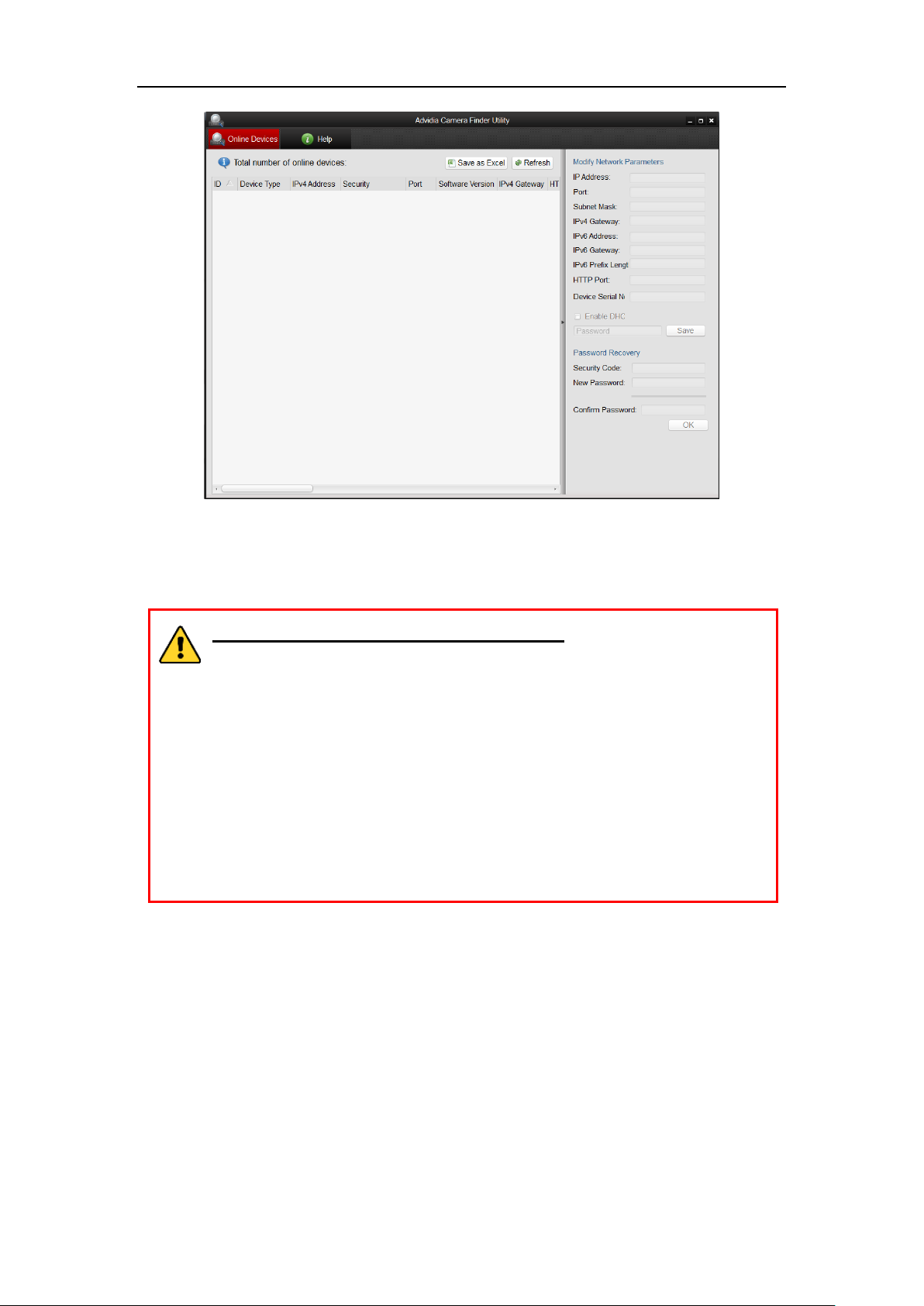
Activation via Advidia Camera Finder Utility
Advidia Camera Finder Utility is used for detecting the online device, activating the
camera, and resetting the password.
Get the Advidia Camera Finder Utility from the supplied disk or the official website,
and install the Advidia Camera Finder Utility according to the prompts. Follow the
steps to activate the camera.
Steps:
1. Run the Advidia Camera Finder Utility software to search the online devices.
2. Check the device status from the device list, and select the inactive device.
12
Network Camera User Manual
Figure 2-4 Advidia Camera Finder Utility Interface
3. Create a password and input the password in the password field, and confirm the
password.
STRONG PASSWORD RECOMMENDED– We highly recommend
you create a strong password of your own choosing (using a minimum
of 8 characters, including at least three of the following categories:
upper case letters, lower case letters, numbers, and special characters) in
order to increase the security of your product. And we recommend you
reset your password regularly, especially in the high security system,
resetting the password monthly or weekly can better protect your
product.
4. Click OK to save the password.
You can check whether the activation is completed on the popup window. If activation
failed, please make sure that the password meets the requirement and try again.
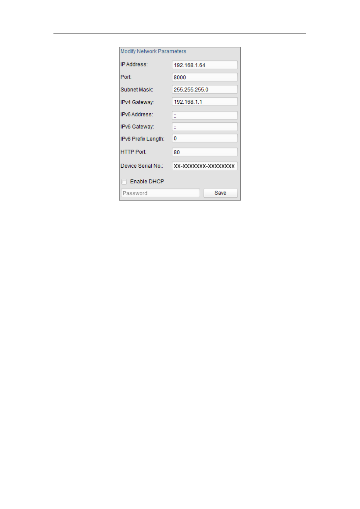
5. Change the device IP address to the same subnet with your computer by either
modifying the IP address manually or checking the checkbox of Enable DHCP.
13
Network Camera User Manual
Figure 2-5 Modify the IP Address
6. Input the password and click the Save button to activate your IP address
modification.
14

User Manual of Network Camera
Chapter 3 Access to the Network
Camera
3.1 Accessing by Web Browsers
Steps:
1. Open the web browser.
2. In the browser address bar, input the IP address of the network camera, and press
the Enter key to enter the login interface.
3. Activate the network camera for the first time using, refer to the Section 2.1.2 for
details.
Note:
The default IP address is 192.0.0.64.
If the camera is not activated, please activate the camera first according to
Chapter 2.1.2.
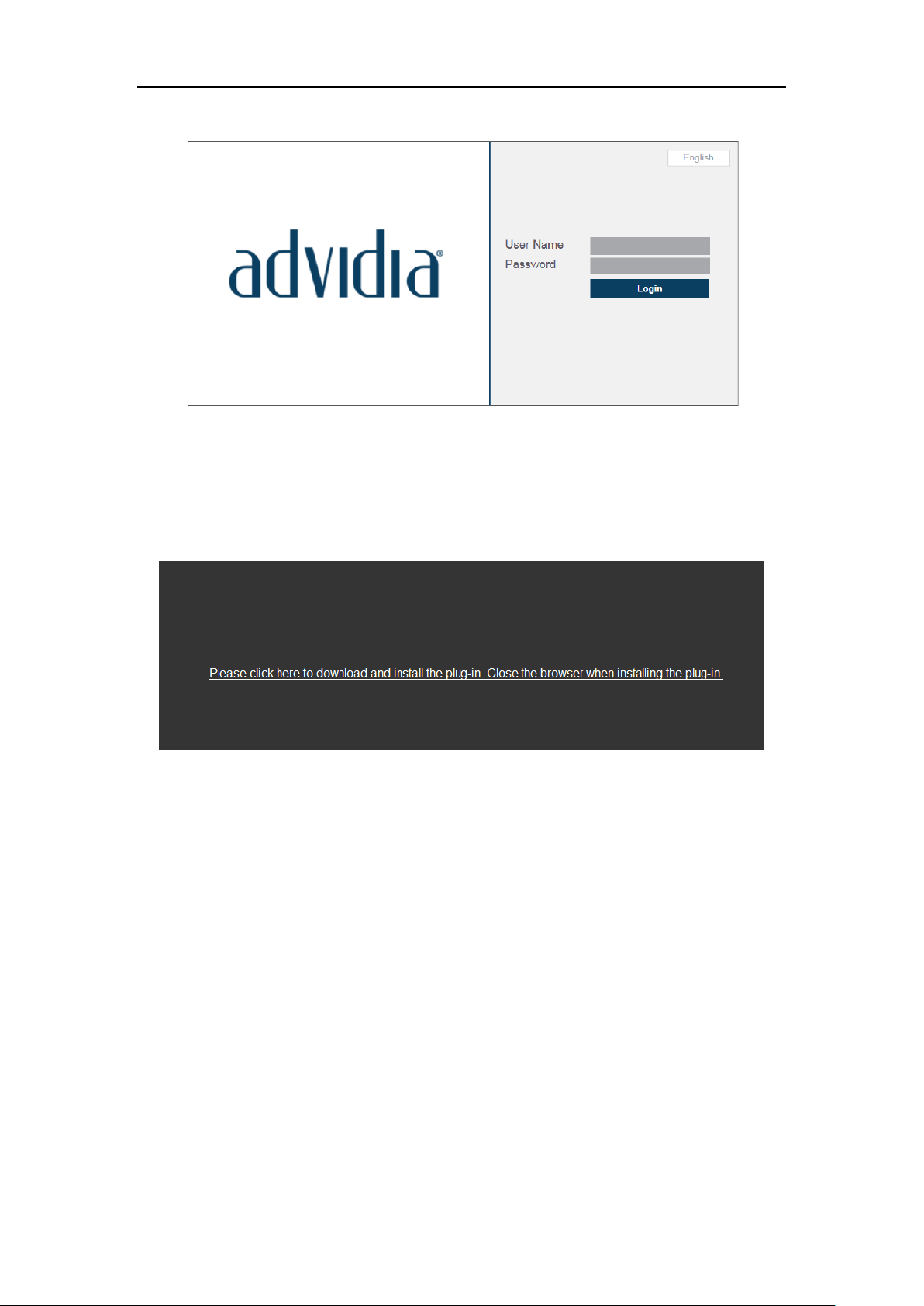
4. Select English as the interface language on the top-right of login interface.
5. Input the user name and password and click Login.
The admin user should configure the device accounts and user/operator permissions
properly. Delete the unnecessary accounts and user/operator permissions.
Note:
The IP address gets locked if the admin user performs 7 failed password attempts
(5 attempts for the user/operator).
15
Network Camera User Manual
Figure 3-1 Login Interface
6. Install the plug-in before viewing the live video and operating the camera. Please
follow the installation prompts to install the plug-in.
Figure 3-2 Download and Install Plug-in
Note: You may have to close the web browser to install the plug-in. Please reopen the
web browser and log in again after installing the plug-in.
16
User Manual of Network Camera
Chapter 4 Live View
4.1 Live View Page
Purpose:
The live view page allows you to view the real-time video, capture images, realize
PTZ control, set/call presets and configure video parameters.
Log in the network camera to enter the live view page, or you can click Live View to
enter the live view page.
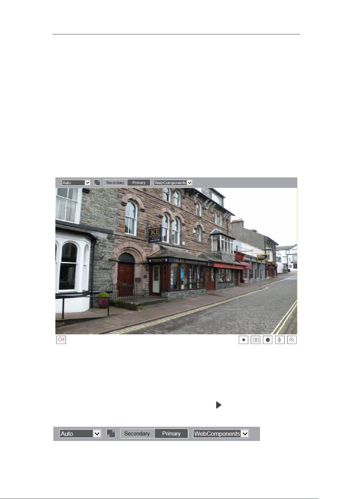
Descriptions of the live view page:
Figure 4-1 Live View Page
4.2 Starting Live View
In the live view window as shown in Figure 4-2, click on the toolbar to start the
live view of the camera.
17
Network Camera User Manual
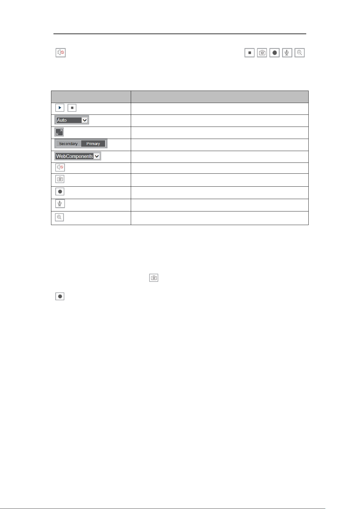
Icon
Description
/
Start/Stop live view.
The window size, 4:3, 16:9, X1 and Auto are optional.
Full screen.
Live view with main and sub stream.
Click to select the third-party plug-in.
Audio on and adjust volume /Mute.
Manually capture the picture.
Manually start/stop recording.
Turn on/off microphone.
Start/stop digital zoom function.
Figure 4-2 Live View Toolbar
Table 4-1 Descriptions of the Toolbar
Note: The icons vary according to the different camera models.
4.3 Recording and Capturing Pictures Manually
In the live view interface, click on the toolbar to capture the live pictures or click
to record the live view. The saving paths of the captured pictures and clips can be
set on the System > Local page.
Note: The captured image will be saved as JPEG file or BMP file in your computer.
18
User Manual of Network Camera
Chapter 5 Network Camera
Configuration
5.1 Configuring Local Parameters
The local configuration refers to the parameters of the live view, record files and
captured pictures. The record files and captured pictures are the ones you record and
capture using the web browser and thus the saving paths of them are on the PC
running the browser.
Steps:
1. Enter the Local Configuration interface: System > Local.
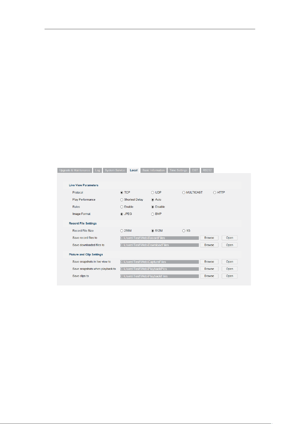
Figure 5-1 Local Configuration Interface
2. Configure the following settings:
Live View Parameters: Set the protocol type and live view performance.
Protocol Type: TCP, UDP, MULTICAST and HTTP are selectable.
TCP: Ensures complete delivery of streaming data and better video quality,
yet the real-time transmission will be affected.
UDP: Provides real-time audio and video streams.
HTTP: Allows the same quality as of TCP without setting specific ports for
19

Network Camera User Manual
streaming under some network environments.
MULTICAST: It’s recommended to select MCAST type when using the
Multicast function.
Play Performance: Set the play performance to Shortest Delay or Auto.
Rules: It refers to the rules on your local browser, select enable or disable to
display or not display the colored marks when the motion detection, face
detection, or intrusion detection is triggered. E.g., enabled as the rules are, and
the face detection is enabled as well, when a face is detected, it will be marked
with a green rectangle on the live view.
Image Format: Choose the image format for picture capture.
Record File Settings: Set the saving path of the recorded video files. Valid for the
record files you recorded with the web browser.
Record File Size: Select the packed size of the manually recorded and
downloaded video files to 256M, 512M or 1G. After the selection, the
maximum record file size is the value you selected.
Save record files to: Set the saving path for the manually recorded video files.
Save downloaded files to: Set the saving path for the downloaded video files
in playback mode.
Picture and Clip Settings: Set the saving paths of the captured pictures and
clipped video files. Valid for the pictures you capture with the web browser.
Save snapshots in live view to: Set the saving path of the manually captured
pictures in live view mode.
Save snapshots when playback to: Set the saving path of the captured
pictures in playback mode.
Save clips to: Set the saving path of the clipped video files in playback mode.
Note: You can click Browse to change the directory for saving the clips and pictures,
and click Open to open the set folder of clips and picture saving.
3. Click Save to save the settings.
20
Network Camera User Manual
5.2 Configure System Settings
Purpose:
Follow the instructions below to configure the system settings, include System
Settings, Maintenance, Security, and User Management, etc.
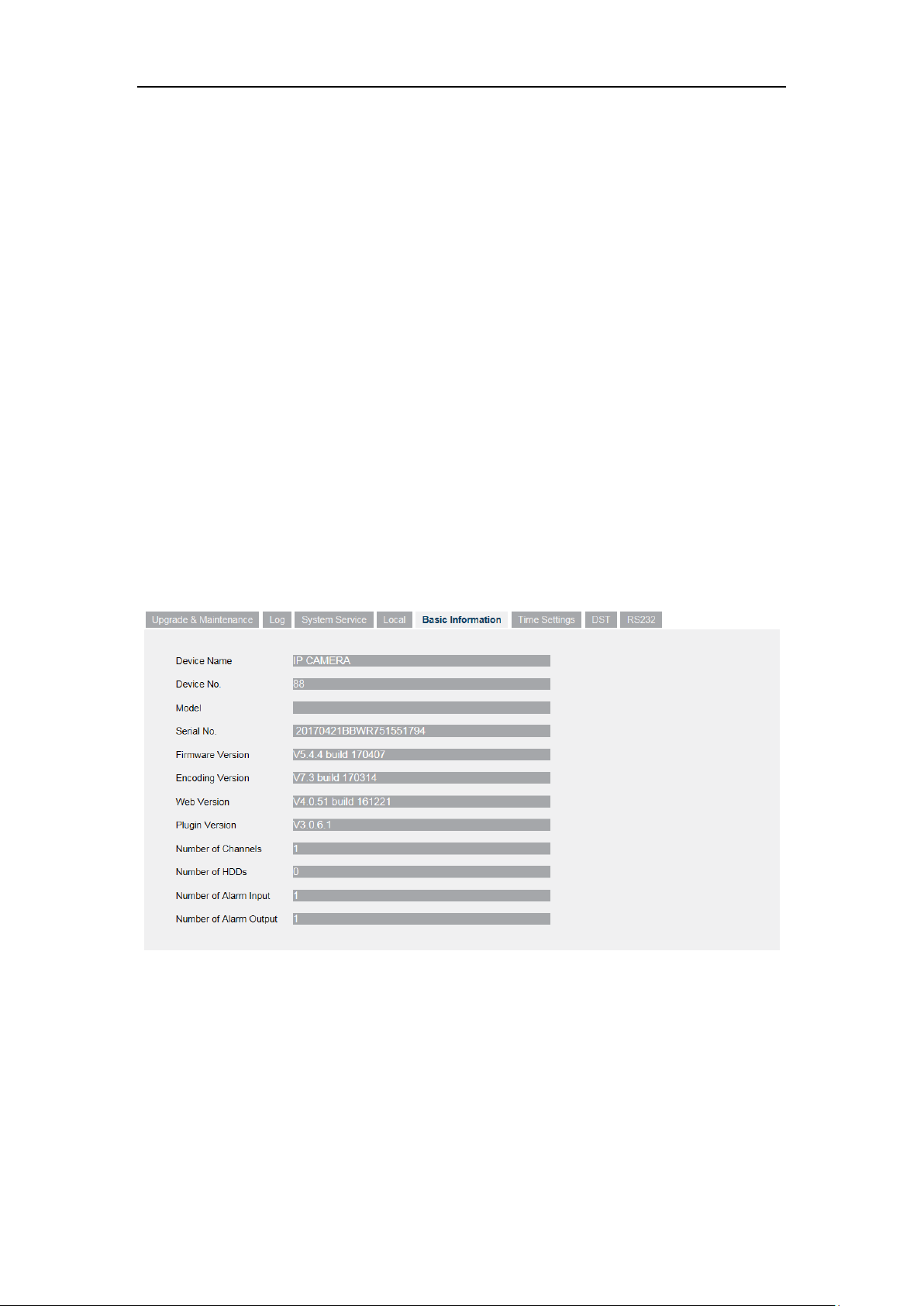
5.2.1 Configuring Basic Information
Enter the Device Information interface: System > Basic Information.
In the Basic Information interface, you can edit the Device Name and Device No..
Other information of the network camera, such as Model, Serial No., Firmware
Version, Encoding Version, Number of Channels, Number of HDDs, Number of
Alarm Input and Number of Alarm Output are displayed. The information cannot be
changed in this menu. It is the reference for maintenance or modification in future.
Figure 5-2 Basic Information
5.2.2 Configuring Time Settings
You can follow the instructions in this section to configure the time synchronization
and DST settings.
21
Network Camera User Manual
Steps:
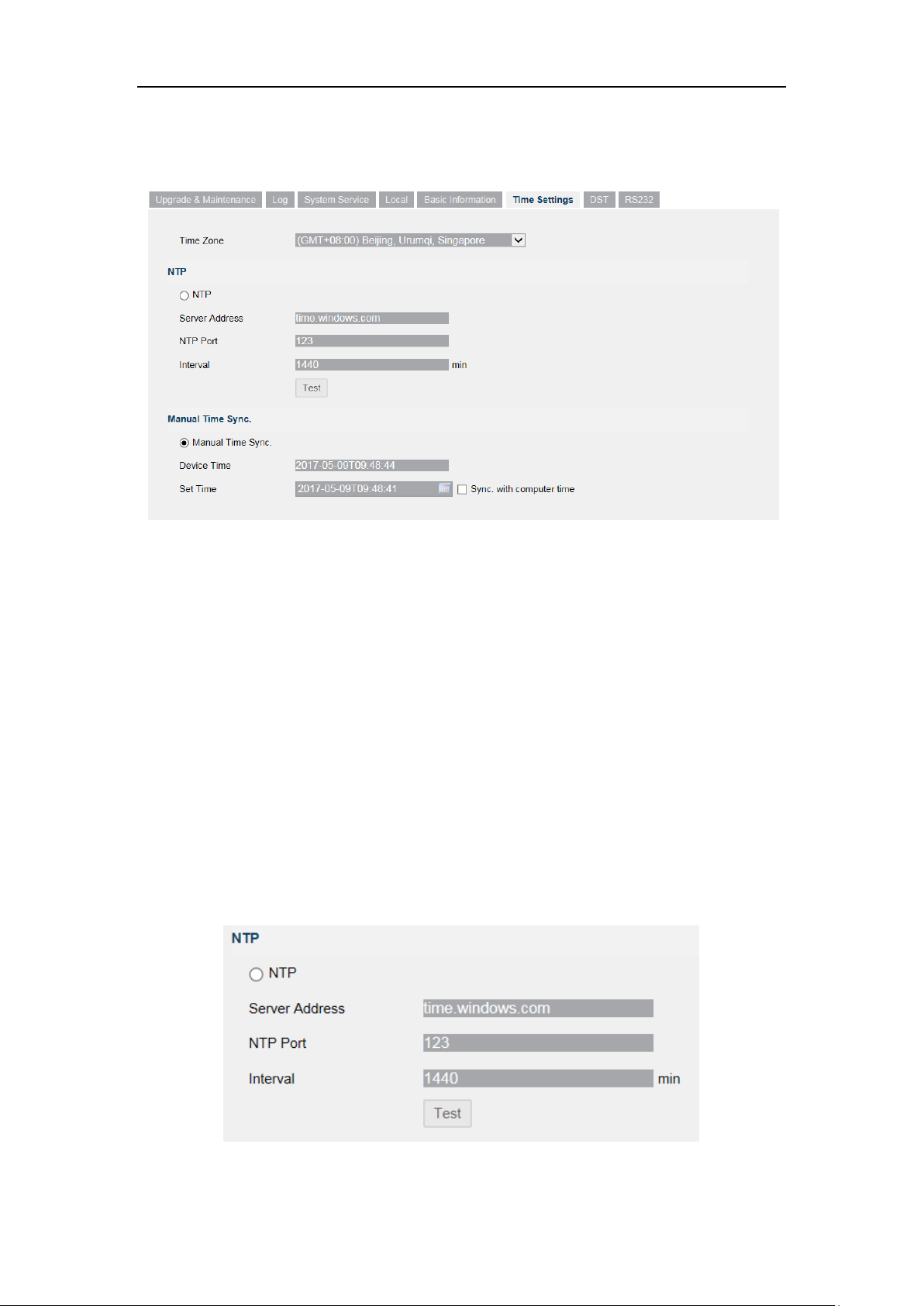
1. Enter the Time Settings interface, System> Time Settings.
Figure 5-3 Time Settings
2. Select the Time Zone of your location from the drop-down menu.
3. Configure the NTP settings.
(1) Click to enable the NTP function.
(2) Configure the following settings:
Server Address: IP address of NTP server.
NTP Port: Port of NTP server.
Interval: The time interval between the two synchronizing actions with NTP
server.
(3) (Optional) You can click the Test button to test the time synchronization
function via NTP server.
Figure 5-4 Time Sync by NTP Server
22
Network Camera User Manual
Note: If the camera is connected to a public network, you should use a NTP server
that has a time synchronization function, such as the server at the National Time
Center (IP Address: 210.72.145.44). If the camera is set in a customized network,
NTP software can be used to establish a NTP server for time synchronization.
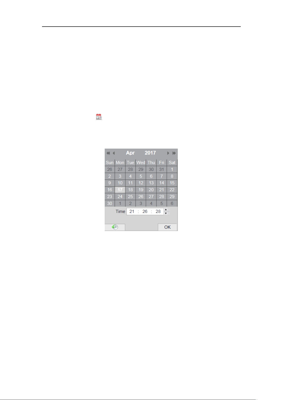
Configure the manual time synchronization.
(1) Check the Manual Time Sync. item to enable the manual time
synchronization function.
(2) Click the icon to select the date, time from the pop-up calendar.
(3) (Optional) You can check Sync. with computer time item to synchronize the
time of the device with that of the local PC.
Figure 5-5 Time Sync Manually
Click Save to save the settings.
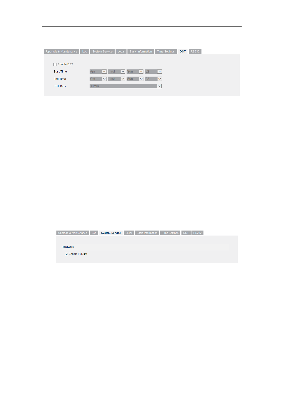
5.2.3 Configuring DST Settings
Purpose:
Daylight Saving Time (DST) is a way of making better use of the natural daylight by
setting your clock forward one hour during the summer months, and back again in the
fall.
Configure the DST according to your actual demand.
Steps:
1. Enter the DST configuration interface.
23
Network Camera User Manual
System > DST
Figure 5-6 DST Settings
2. Select the start time and the end time.
3. Select the DST Bias.
4. Click Save to activate the settings.
5.2.4 System Service
System service settings refer to the software and hardware service the camera
supports. Supported functions vary according to the different cameras. For the
cameras support IR LED, ABF (Auto Back Focus), Auto Defog, or Status LED, you
can select to enable or disable the corresponding service according to the actual
demands.
Figure 5-7 Enable IR Light
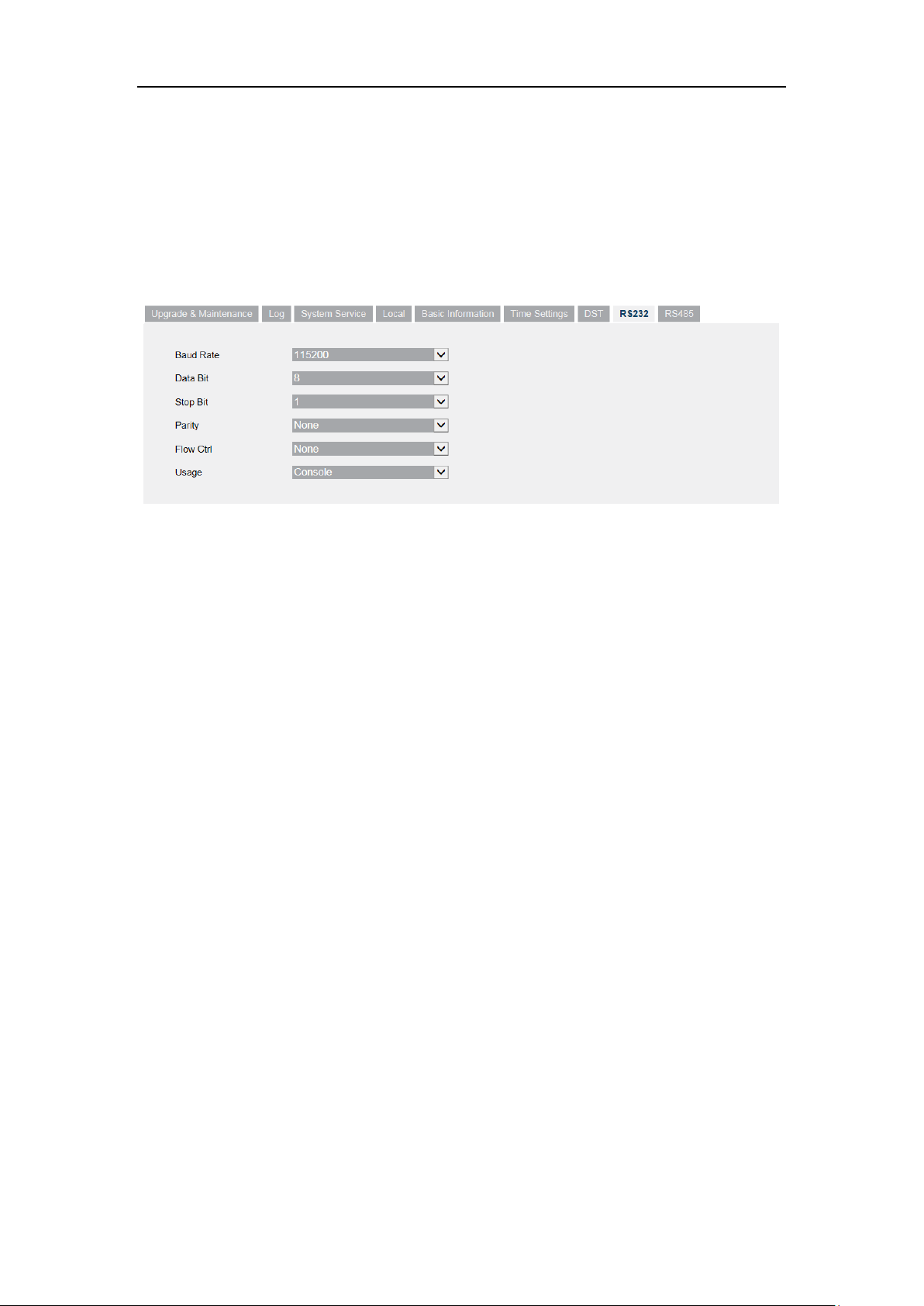
5.2.5 Configuring RS232 Settings
The RS232 port can be used in two ways:
Parameters Configuration: Connect a computer to the camera through the serial
port. Device parameters can be configured by using software such as
HyperTerminal. The serial port parameters must be the same as the serial port
parameters of the camera.
24
Network Camera User Manual
Transparent Channel: Connect a serial device directly to the camera. The serial
device will be controlled remotely by the computer through the network.
Steps:
1. Enter RS232 Port Setting interface: System > RS232.
2. Configure the Baud Rate, Data Bit, Stop Bit, Parity, Flow Control, and Usage.
Figure 5-8 RS232 Settings
Note: If you want to connect the camera by the RS232 port, the parameters of the
RS232 should be exactly the same with the parameters you configured here.
3. Click Save to save the settings.
5.3 Maintenance
5.3.1 Upgrade & Maintenance
The upgrade & maintenance interface allows you to process the operations, including
reboot, partly restore, restore to default, export/import the configuration files, and
upgrade the device.
Enter the Maintenance interface: System > Upgrade & Maintenance
Restore: Reset all the parameters, except the IP parameters and user information,
to the default settings.
Default: Restore all the parameters to the factory default.
Note: After restoring the default settings, the IP address is also restored to the
default IP address, please be careful for this action.
Export/Import Config. File: Configuration file is used for the batch
25

Network Camera User Manual
configuration of the camera, which can simplify the configuration steps when
there are a lot of cameras needing configuring.
Steps:
1. Click Device Parameters to export the current configuration file, and save it
to certain place.
2. Click Browse to select the saved configuration file and then click Import to
start importing configuration file.
Note: You need to reboot the camera after importing configuration file.
Upgrade: Upgrade the device to a certain version.
Steps:
1. Select firmware or firmware directory to locate the upgrade file.
Firmware: Locate the exact path of the upgrade file.
Firmware Directory: Only the directory the upgrade file belongs to is
required.
2. Click Browse to select the local upgrade file and then click Upgrade to start
remote upgrade.
Note: The upgrading process will take 1 to 10 minutes. Please don't disconnect
power of the camera during the process, and the camera reboots automatically
after upgrade.
5.3.2 Log
The operation, alarm, exception and information of the camera can be stored in log
files. You can also export the log files on your demand.
Before you start:
Please configure network storage for the camera or insert a SD card in the camera.
Steps:
1. Enter log searching interface: System > Log.
26
 Loading...