

Panasonic 9TAWX-C3010 User Manual
Before attempting to connect or operate this product,
please read these instructions carefully and save this manual for future use.
No model number suffix is shown in this Operating Instructions.
Center Module
Operating Instructions
Model No. WX-C3010
ENGLISH
FRANÇAIS
AUX IN
A
E
C
UX
H
O
C
TALK
ANC
SP
E
LLE
R
D
N
PAG
R
D
LE
E
BEEP
IN
O
UTSIDE
SP
M
O
SPEE
D
TEA
BEE
M
DAY
O
U
A
V
L L
EL
A
N
R
E
D
MAX
YELLO
GREEN LOW
OFF
OFF
S
T
A
L
L
PREV
IC
P
ERA
T
P
/
N
IGHT
N:
DAY
E
LA
N
E
S
E
LE
CT
W
M
P
D
O
S
TX
S
Y
S
T
E
M
S
E
T
T
SEL
NEXT
AUX
S
P
M
I
C
I
O
N
A
L
S
E
T
T
IN
G
O
UTSIDE
SP LE
VEL
V/
O
O
VERR
N:
DAY
TELE
RE
M
P
O
W
IN
G
BEEP
DET
I
DE
PHO
O
T
E
E
R
RELEASE
NE
CO
N
T
RO
L O
UT
I
D R
E
G
IS
T
R
A
T
I
O
POS
AUDI
O
O
SELECT
1
2
T
/
P
HE
PLAYBA
N
G
REE
N
START
DELAY
A
DSET
CK
AUX
POW
T
E
R
E
R
REC
V
O
L
UME
DO
WN
T
A
L
K
UP
PA
DESTIN
A
TI
HEADSET
G
E
O
N
VEHI
C
L
E
D
E
T
E
C
TO
R
2
FEDERAL COMMUNICATIONS COMMISSION INTERFERENCE STATEMENT
This equipment has been tested and found to comply with the limits for a Class A digital device, pursuant to part 15 of the
FCC Rules. These limits are designed to provide reasonable protection against harmful interference when the equipment is
operated in a commercial environment. This equipment generates, uses, and can radiate radio frequency energy and, if not
installed and used in accordance with the instruction manual, may cause harmful interference to radio communications.
Operation of this equipment in a residential area is likely to cause harmful interference in which case the user will be
required to correct the interference at his own expense.
FCC Warning: This transmitter must not be co-located or operated in conjunction with any other antenna or transmitter.
FCC Warning: This equipment complies with FCC radiation exposure limits set forth for uncontrolled equipment and meets
the FCC radio frequency (RF) Exposure Guidelines in Supplement C to OET65. This equipment should be installed and
operated with at least 20 cm and more between the radiator and person's body (excluding extremities: hands, wrists, feet
and legs).
FCC Warning: To assure continued FCC emission limit compliance, use only the provided power supply cord and shielded
interface cable when connecting this device to the computer. Also, any unauthorized changes or modifications to this equipment would void the user's authority to operate this device.
This device complies with Part 15 of the FCC Rules. Operation is subject to the following two conditions: (1) This device
may not cause harmful interference, and (2) this device must accept any interference received, including interference that
may cause undesired operation.
Responsible Party: Panasonic Corporation of North America
One Panasonic Way, Secaucus, NJ 07094
Technical Support Party: Panasonic Consumer Electronics Company
1707 N. Randall Rd., Elgin IL. 60123
Technical Support Tel No.: 886-472-6767
For U.S.A.
The lightning flash with arrowhead symbol,
within an equilateral triangle, is intended to
alert the user to the presence of uninsulated
"dangerous voltage" within the product's
enclosure that may be of sufficient magnitude to constitute a risk of electric shock to
persons.
CAUTION: TO REDUCE THE RISK OF ELECTRIC SHOCK,
DO NOT REMOVE COVER (OR BACK).
NO USER-SERVICEABLE PARTS INSIDE.
REFER SERVICING TO QUALIFIED SERVICE PERSONNEL.
CAUTION
RISK OF ELECTRIC SHOCK
DO NOT OPEN
The exclamation point within an equilateral
triangle is intended to alert the user to the
presence of important operating and maintenance (servicing) instructions in the literature
accompanying the appliance.
The model number and serial number of this product may be
found on the surface of the unit.
You should note the model number and serial number of this
unit in the space provided and retain this book as a permanent record of your purchase to aid identification in the event
of theft.
Model No.
Serial No.
For U.S.A.
3
WARNING:
• This apparatus must be earthed.
• Apparatus shall be connected to a main socket outlet with a protective earthing connection.
• The mains plug or an appliance coupler shall remain readily
operable.
• To reduce the risk of fire or electric shock, do not expose this
apparatus to rain or moisture.
• The apparatus should not be exposed to dripping or splashing
and that no objects filled with liquids, such as vases, should be
placed on the apparatus.
• All work related to the installation of this product should be made
by qualified service personnel or system installers.
• To prevent injury, this apparatus must be securely attached to
the floor/wall in accordance with the installation instructions.
• The connections should comply with local electrical code.
• The risk of hearing impairment due to exposure to excessive
sound levels may be reduced by listening at lower volumes and
for shorter durations.
RSS-213
Operation is subject to the following two conditions: (1) this
device may not cause interference, and (2) this device must
accept any interference, including interference that may cause
undesired operation of the device.
ATTENTION:
A lithium-ion battery that is recyclable powers the product you have purchased. Please call 1-800-8-BATTERY
for information on how to recycle this battery.
CAUTION:
• Danger of explosion if battery is incorrectly replaced. Replace
only with the same or equivalent type.
• These servicing instructions are for use by qualified service personnel only. To reduce the risk of electric shock do not perform
any servicing other than that contained in the operating instructions unless you are qualified to do so.
For Canada
ENGLISH
CAUTION
The FCC ID number for this radio equipment is listed below.
FCC ID: ACJ9TAWX-C3010
For U.S.A.
ICES-003
This Class A digital apparatus complies with Canadian ICES-003.
For Canada

4
Limitation of Liability
THIS PUBLICATION IS PROVIDED "AS IS" WITHOUT WARRANTY OF ANY KIND, EITHER EXPRESS OR IMPLIED, INCLUDING
BUT NOT LIMITED TO, THE IMPLIED WARRANTIES OF MERCHANTABILITY, FITNESS FOR ANY PARTICULAR PURPOSE, OR
NON-INFRINGEMENT OF THE THIRD PARTY'S RIGHT.
Disclaimer of Warranty
IN NO EVENT SHALL Panasonic Corporation BE LIABLE TO
ANY PARTY OR ANY PERSON, EXCEPT FOR REPLACEMENT OR REASONABLE MAINTENANCE OF THE PRODUCT, FOR THE CASES, INCLUDING BUT NOT LIMITED TO
BELOW:
(1) ANY DAMAGE AND LOSS, INCLUDING WITHOUT LIMI-
TATION, DIRECT OR INDIRECT, SPECIAL, CONSEQUENTIAL OR EXEMPLARY, ARISING OUT OF OR
RELATING TO THE PRODUCT;
(2) PERSONAL INJURY OR ANY DAMAGE CAUSED BY
INAPPROPRIATE USE OR NEGLIGENT OPERATION OF
THE USER;
(3) UNAUTHORIZED DISASSEMBLE, REPAIR OR MODIFI-
CATION OF THE PRODUCT BY THE USER;
(4) ANY PROBLEM, CONSEQUENTIAL INCONVENIENCE,
OR LOSS OR DAMAGE, ARISING OUT OF THE SYSTEM
COMBINED BY THE DEVICES OF THIRD PARTY;
(5) PERSONAL INJURY, ANY LOSS OR DAMAGE, ARISING
OUT OF THE DROP CAUSED BY THE INCOMPLETE
INSTALLATION.

5
Important Safety Instructions
1) Read these instructions.
2) Keep these instructions.
3) Heed all warnings.
4) Follow all instructions.
5) Do not use this apparatus near water.
6) Clean only with dry cloth.
7) Do not block any ventilation openings. Install in accordance with the manufacturer's instructions.
8) Do not install near any heat sources such as radiators, heat registers, stoves, or other apparatus (including amplifiers) that
produce heat.
9) Do not defeat the safety purpose of the polarized or grounding-type plug. A polarized plug has two blades with one wider
than the other. A grounding type plug has two blades and a third grounding prong. The wide blade or the third prong are
provided for your safety. If the provided plug does not fit into your outlet, consult an electrician for replacement of the obsolete outlet.
10) Protect the power cord from being walked on or pinched particularly at plugs, convenience receptacles, and the point
where they exit from the apparatus.
11) Only use attachments/accessories specified by the manufacturer.
12) Use only with the cart, stand, tripod, bracket, or table specified by the manufacturer, or sold with the apparatus. When a cart
is used, use caution when moving the cart/apparatus combination to avoid injury from tip-over.
13) Unplug this apparatus during lightning storms or when unused for long periods of time.
14) Refer all servicing to qualified service personnel. Servicing is required when the apparatus has been damaged in any way,
such as power-supply cord or plug is damaged, liquid has been spilled or objects have fallen into the apparatus, the apparatus has been exposed to rain or moisture, does not operate normally, or has been dropped.
S3125A

6
Limitation of Liability ................................................................................................................................... 4
Disclaimer of Warranty ............................................................................................................................... 4
Important Safety Instructions ...................................................................................................................... 5
Preface ....................................................................................................................................................... 7
Features ...................................................................................................................................................... 7
Precautions ................................................................................................................................................. 8
Operations ................................................................................................................................................. 9
Major Operating Controls and Their Functions .......................................................................................... 9
■ WX-C3010 Center Module .................................................................................................................... 9
Operating Procedures ................................................................................................................................ 12
■ Basic Operation .................................................................................................................................... 12
● Power ON ......................................................................................................................................... 12
● Communications with Customers (TALK) ......................................................................................... 12
● Communications with other Store Personnel (PAGE) ....................................................................... 12
● Double Drive-Thru Lane Changeover ............................................................................................... 12
● Power OFF ........................................................................................................................................ 12
■ Convenient Functions ........................................................................................................................... 12
● Auto Talk Lock .................................................................................................................................. 12
● Manager Mode ................................................................................................................................. 12
● Speed Term ...................................................................................................................................... 12
● Greeter .............................................................................................................................................. 13
● Vehicle Detector BEEP DAY/NIGHT ................................................................................................. 14
● Outside Speaker Level DAY/NIGHT ................................................................................................. 14
● Vehicle Detector Normal/Override On .............................................................................................. 15
● Talk/Page Release ............................................................................................................................ 15
Installation & Connections ...................................................................................................................... 16
Panasonic WX-C3010 Series System Parts and Accessories .................................................................... 16
Major Operating Controls and Their Functions .......................................................................................... 17
Installations/Connections ........................................................................................................................... 19
■ Installation procedures ........................................................................................................................ 19
■ Preparations ......................................................................................................................................... 19
■ Installation of center modules on the wall ............................................................................................ 19
■ Wiring to the center modules ............................................................................................................... 20
■ Clamping the Power Plug and Power Cord .......................................................................................... 21
■ Basic Connection ................................................................................................................................. 22
■ POS (Point of sales)-System Connection ............................................................................................. 23
■ Double-Drive-Thru Connection ............................................................................................................. 24
■ ID registration for follower units ............................................................................................................ 25
■ Installed System Setting ....................................................................................................................... 26
● Setup operation for AUX SP (Auxiliary Speaker) .............................................................................. 26
● Setup operation for Echo Canceller (Echo Canceller Effect Level Control) ..................................... 27
● Setup operation for DNR Level (Digital Noise Reduction Effect Level Control) ............................... 27
● Setup operation for Dual Lane .......................................................................................................... 28
● Lane setup ........................................................................................................................................ 29
● POS Remote setup ........................................................................................................................... 29
● TX Power setup ................................................................................................................................. 29
■ Info about POS Remote functions ........................................................................................................ 30
Maintenance & Specifications ................................................................................................................. 31
Troubleshooting........................................................................................................................................... 31
Specifications ............................................................................................................................................. 33
Standard accessories ................................................................................................................................ 34
CONTENTS

7
Preface
Center Module WX-C3010 is exclusively designed for Panasonic Wireless Communication System, which is used with drive-thru
menu boards, etc. The system operates on 1.9 GHz DECT.
Features
• 1.9 GHz DECT* is used with center module to prevent the interference from microwave ovens or wireless LAN used with 2.4
GHz DECT.
Four-channel simultaneous communication in full duplex (TALK & PAGE) using DECT technology facilitates workflows at
drive-thrus, and digital technology enables simultaneous communications. DECT technology can be used even in the
places where wiring is difficult.
*Digital Enhanced Cordless Telecommunications
• DNR (Digital Noise Reduction)
DNR function, processed in the Digital Signal Processor (DSP), reduces noise to improve sound quality.
• Acoustic Echo Canceller eliminates acoustic echo at the menu board.
• Greeter
When a customer approaches the menu board, the message* recorded in the center module is automatically output from
the menu board speaker.
* Up to two messages can be recorded.
• Four-channel simultaneous communication
The total number of All-in-One Headsets and Order Takers that can be registered is 32. Up to four operators can communicate at the same time using All-in-One Headsets and Order Takers.
• Manager mode
It is possible to set the manager mode to one of the registered All-in-One Headsets or Order Takers. A person using this
headset or Order Taker has the priority of communication.

8
Precautions
• Handle this product with care. The product contains sensitive components that can be damaged by improper handling or
storage.
• Repair or replace any defective components.
• Use this product for indoor use only.
• Do not expose this product to direct sunlight for hours and do not install the product near a heater or an air conditioner.
Otherwise, it may cause deformation, discoloration and malfunction. Keep this product away from water.
• Avoid installing in the following locations.
• Locations where a chemical agent is used such as a swimming pool
• Locations under the air conditioner
• Locations near the fryer
• Locations near the grill
• Locations in a humid or dust-laden environment
• Locations near flammable gas or vapor
• Locations where radiation or x-ray emissions are produced
• Locations subject to strong magnetic field or radio waves
• Locations where corrosive gas is produced
• Locations where it may be damaged by briny air such as seashores
• Locations subject to vibrations (This product is not designed for on-vehicle use.)
• Be sure to remove this product if it is not in use.
• Avoid connections during a lightning storm. Otherwise, an electric shock may be caused.
9
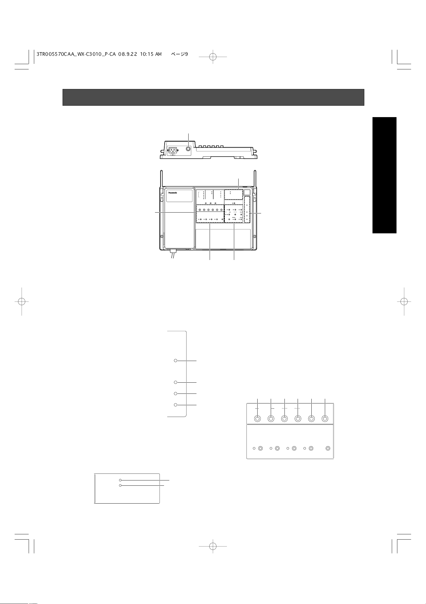
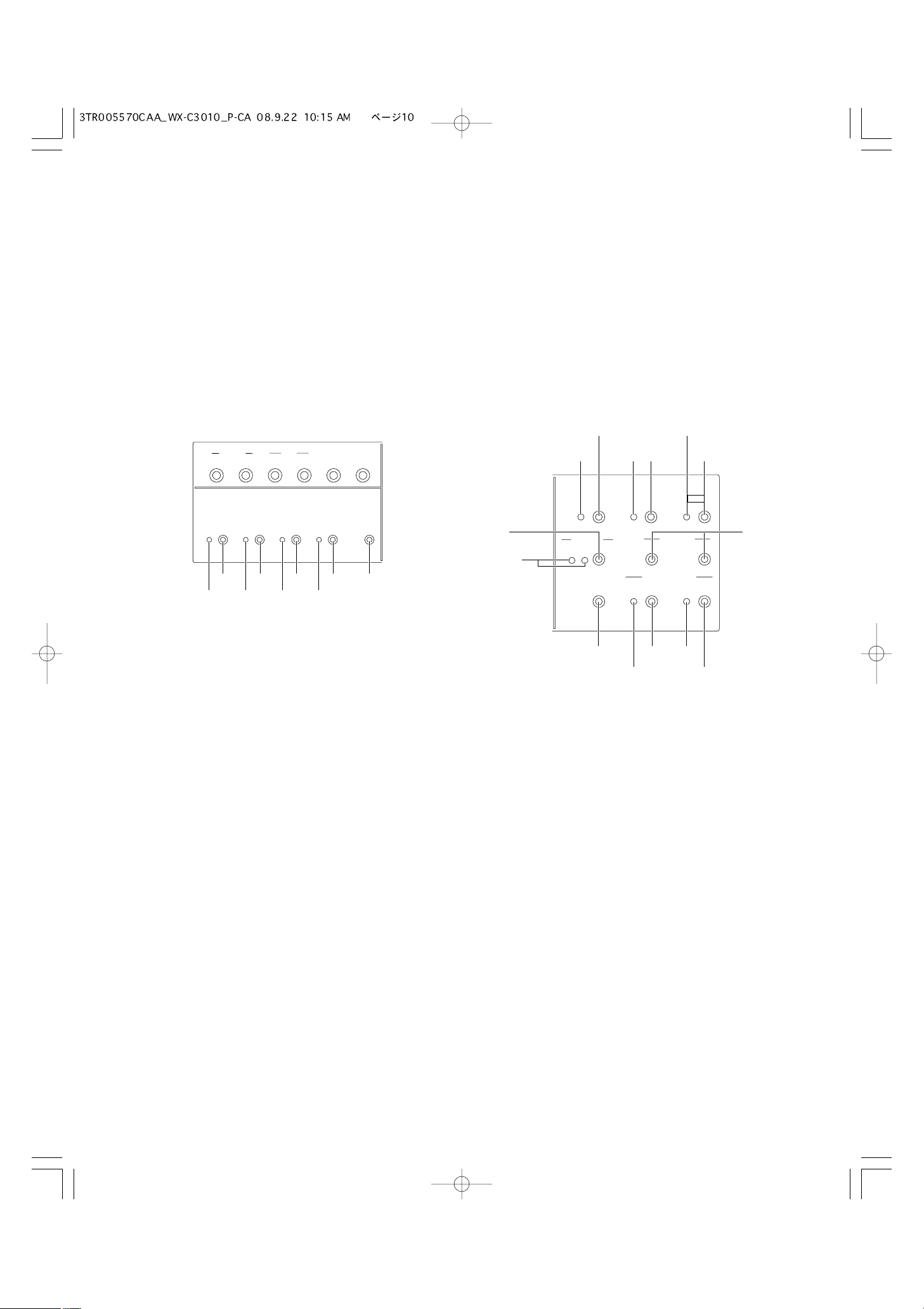
Major Operating Controls and Their Functions
q Power ON/OFF Switch
This switch turns the power of the center module on and
off.
[COMMUNICATION INDICATORS]
w Power Indicator (Green) (POWER)
This indicates that the power of center module is on.
e Talk/Gooseneck Microphone/
Indicator (Yellow) (TALK)
This lights up during conversation
with customers.
r Page Indicator (Green) (PAGE)
This lights up during conversation
among store personnel.
t Vehicle Detector Indicator (Yellow)
(VEHICLE DETECTOR)
This lights up when a vehicle is sensed by the vehicle
detector. The indicator blinks while the speed team
mode is active.
[CONTROL INDICATORS]
y Telephone Indicator (Green) (TELEPHONE)
When the Order Taker or the All-in-One Headset is set in
the manager mode and the Optional Function Button [R]
is pressed on the Order Taker or All-in-One Headset
side, operation cannot be forwarded for talking or paging. At that time, this indicator lights.
When the Optional Function Button is pressed on the
Order Taker or All-in-One Headset side again, the talk or
page operation is recovered. The Telephone Indicator is
turned OFF.
u Control Output Indicator (Green) (CONTROL OUT)
This indicator lights while the external control.
[VOLUME CONTROLS]
i Outside Speaker Volume (OUTSIDE, SP)
This control sets the output level of outside speaker.
o Outside Microphone Volume (OUTSIDE, MIC)
This control sets the input level of outside microphone.
■ WX-C3010 Center Module
q
io!0!1!2!
Operations
CONTROL INDICATORS
VOLUME CONTROLS
OPERATIONAL SETTING
POWER
w
T
A
LK
PA
GE
VEH
IC
DETECTOR
LE
e
r
t
GREETER
COMMUNICATION
INDICATORS
OUTSIDE
SP
MIC
OPERATIONAL SETTING
BEEP
SPEED
DAY/NIGHT
TEAM
ON:DAY
AUX
SP
OUTSIDE
SP LEVEL
ON:DAY
MIC
BEEP
V/DET
OVERRIDE
POS
AUDIO
T/P
RELEASE
3
TELEPHONE
CONTROL OUT
y
u
10
!0 Auxiliary Speaker Volume (AUX, SP)
This control sets the output level of auxiliary speaker.
!1 Auxiliary Microphone Volume (AUX, MIC)
This control sets the input level of gooseneck microphone.
!2 Vehicle Detector Beep Volume (BEEP)
This control sets the vehicle detection beep tone for the
Order Taker or the All-in-One Headset.
!3 POS Audio Volume (POS AUDIO)
This control sets the input level of POS audio.
[OPERATIONAL SETTING]
!4 Speed Team Indicator (yellow) (SPEED TEAM)
This indicates that the speed team mode is on.
!5 Speed Team On/Off Button
This button turns the speed team mode on and off.
!6 Vehicle Detector Beep Day/Night Indicator (yellow)
(BEEP DAY/NIGHT ON:DAY)
This indicates that the vehicle detector beep has selected DAY.
!7 Vehicle Detector Beep Day/Night Button
This button turns the vehicle detector beep DAY and
NIGHT.
Day mode: Disables the vehicle detector beep on the
other lane.
Night mode: Reduces the volume of the vehicle detec-
tor beep on the other lane.
!8 Outside Speaker Level Indicator (yellow) (OUTSIDE
SP LEVEL ON:DAY)
This indicates that the outside speaker level has selected normal level.
!9 Outside Speaker Level DAY/NIGHT Button
This button turns the outside speaker level normal level
and 50% level.
@0 Vehicle Detector Normal/Override On Indicator (yel-
low) (V/DET OVERRIDE)
This indicates that the vehicle detector has selected
Override On.
@1 Vehicle Detector Normal/Override On Button
This button turns the vehicle detector Normal and
Override On.
NORMAL: The vehicle detector turns on only when vehi-
cle is detected at the menu board.
OVERRIDE ON: The vehicle detector is always turned
on.
@2 Talk/Page Release Button (T/P RELEASE)
The button is used to release temporarily the talk/page
communication of the Order Taker or All-in-One
Headset.
[GREETER]
@3 Greeter On/Off Indicator (yellow) (GREETER, ON)
This indicates that the greeter function has selected on.
@4 Greeter On/Off Button (GREETER, ON)
This button turns the greeter function on and off.
@5 Greeter Memory Select and Output Level Indicator
(green/yellow/red) (SELECT)
This indicates that the greeter memory has been selected. Each memory has a capacity to record a message
for 16 seconds at the maximum.
1: This indicates that the greeter memory has selected
1. (The message of “Please pull forward” is a factory
default.)
2: This indicates that the greeter memory has selected
2.
Off: Greeter is Off.
Green: When the greeter output level set in LOW, the
indicator lights up in green.
Yellow: When the greeter output level set in MID, the
indicator lights up in yellow.
Red: When the greeter output level set in HIGH, the indi-
cator lights up in red.
@6 Greeter Memory Select Button (SELECT)
This button selects either of the greeter memories.
@
#
#
OUTSIDE
SP
MIC
AUX
SP
MIC
BEEP
SPEED
TEAM
OPERATIONAL SETTING
BEEP
OUTSIDE
DAY/NIGHT
SP LEVEL
ON:DAY
ON:DAY
V/DET
OVERRIDE
!5 !7 !9 @1 @2
!4 !6 !8 @0
POS
AUDIO
T/P
RELEASE
@6
@3
SELECT
2
1
ON
4
@7
GREETER
START
DELAY
@8
DOWN
VOLUME
@5
HEADS
ET
PLAYBACK
DESTINATION
AUX
HEADSET
@9
#0
REC
#1
UP
#2
3
#4
#5
6

11
@7 Greeter Start Delay Indicator (Yellow)
(START DELAY)
This indicates that the greeter start delay has selected
on.
@8 Greeter Start Delay Button (START DELAY)
This button turns the greeter start delay normal and
delay.
@9 Greeter Record Indicator (Red) (REC)
This indicates that while recording in the selected
greeter memory (1 or 2).
#0 Greeter Record Button (REC)
When this button is pushed, the message from Order
Taker or All-in-One Headset is recorded in the selected
greeter memory (1 or 2).
#1 Greeter Output Level Down/Up Buttons (VOLUME,
UP/DOWN)
These buttons go up or down the output level of greeter.
According to the operations on the buttons, the SELECT
indicator changes the indication.
#2 Greeter Playback Button (HEADSET PLAYBACK)
When this button is pressed, Order Taker or All-in-One
Headset plays back the message from selected greeter.
#3 Greeter Output Auxiliary Speaker Indicator (Green)
(DESTINATION, AUX)
This indicator lights when the greeter message output is
provided through the auxiliary speaker.
#4 Greeter Output Auxiliary Speaker Button (DESTINA-
TION, AUX)
This button selects the greeter output to the auxiliary
speaker On and Off.
#5 Greeter Output Headset Indicator (Green) (DESTINA-
TION, HEADSET)
This indicates that the greeter output to the headset is
on.
#6 Greeter Output Headset Button (DESTINATION,
HEADSET)
This button selects the greeter output to the headset On
and Off.

12
Operating Procedures
■ Basic Operation
● Power ON
Press the Power ON/OFF Switch of the center module to turn
the power supply ON.
It takes about 5 seconds until the power supply is started.
Then, press the Power buttons of the Order Taker and the
All-in-One Headset to turn their power supplies ON.
● Communications with Customers (TALK)
Store personnel wearing the headset can communicate bidirectionally with any customer who is at the menu board.
In regard to the method of talking, refer to the operating
instructions of the Order Taker (WX-T3020) or the All-in-One
Headset (WX-H3050).
● Communications with other Store Personnel
(PAGE)
Store personnel wearing the headset can communicate with
each other without being heard by customers.
In regard to the method of paging, refer to the operating
instructions of the Order Taker (WX-T3020) or the All-in-One
Headset (WX-H3050).
● Double Drive-Thru Lane Changeover
In the case of double drive-thru, it is possible to talk or page
by selecting either Lane A or Lane B.
In regard to the method of lane changeover operation, refer
to the operating instructions of the Order Taker (WX-T3020)
or the All-in-One Headset (WX-H3050).
● Power OFF
To turn the power supply OFF, keep pressing the Power button of the Order Taker or the All-in-One Headset for more
than 2 seconds.
Lastly, press the Power ON/OFF switch of the center module
to turn its power supply OFF.
■ Convenient Functions
● Auto Talk Lock
When a customer approaches the menu board, it is automatically possible to make the predetermined personnel’s
headset (Order Taker or All-in-One Headset) stay in TALK
state. (The Talk Lock Mode is assumed.)
In regard to the method of Auto Talk Lock Mode setup, refer
to the operating instructions of the Order Taker (WX-T3020)
or the All-in-One Headset (WX-H3050).
● Manager Mode
You can set one headset (Order Taker or All-in-One
Headset) to the manager mode in a Lane. Refer to the operation manual of Order Taker or All-in-One Headset about the
setting method. The headset set to the MANAGER MODE
has following functionality.
• The manager can interrupt store personnel's TALK or
PAGE at any time by monopolizing one channel by priority.
• The Manager can hear audio from POS alone (setting
necessary)
● Speed Team
This SPEED TEAM operation is used at the congestion time.
Doesn't use the outside microphone and speaker. An Order
Taker or All-in-One Headset communicates order from outside into the store.s
1. Press the SPEED TEAM button of the Center Module.
2. The Order Taker or All-in-One Headset allows the operator to hear the voice prompt of the "SPEED TEAM ON".
3. The Order Taker or All-in-One Headset allows the operator to communicate by pressing the PAGE button.
4. Press the PAGE button, and communication can be performed in the PAGE-LOCK mode. (Even if the PAGE button is set to PTP, it operates by PAGE-LOCK.)
SPEED
TEAM
OPERATIONAL SETTING
BEEP
OUTSIDE
DAY/NIGHT
SP LEVEL
ON:DAY
Speed Term On/Off Button
ON:DAY
V/DET
OVERRIDE
T/P
RELEASE
13
5. Press the SPEED TEAM button of the Center Module
again, the SPEED TEAM mode will be released. The
Order Taker or All-in-One Headset allows the operator to
hear the voice prompt of the "SPEED TEAM OFF".
Notes:
• TALK is prohibited in the speed team mode.
If TALK is attempted with the Order Taker or the Allin-One Headset, a voice prompt of "Operation not
allowed" is heard from the headset speaker.
• If POS Remote is set for ON, you have to note that
no button operation of the speed team is possible at
the center module.
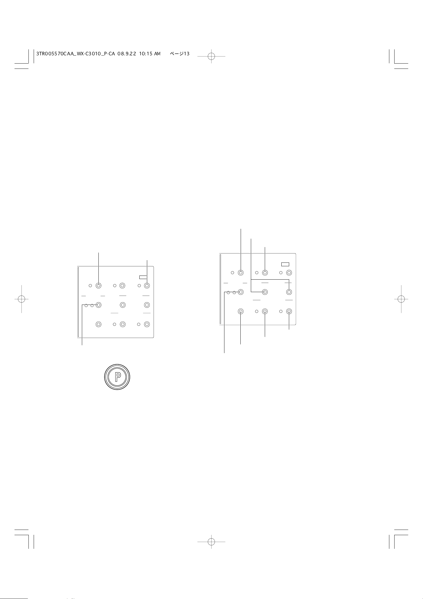
● Greeter
When the customer approaches the menu board, the voice
message recorded in the Center Module is automatically
output to the outside speaker. The Center Module has two
memories, and you can select either message.
[Method of recording message]
1. Press the Greeter ON/OFF Button of the Center Module.
The Greeter ON/OFF Indicator will light in yellow.
2. Press the Greeter Memory Select Button of Center
Module and select the memory 1 or 2.
3. Press the Greeter Record Button of Center Module. The
Greeter Record Indicator will light in red.
4. Hold down the PAGE button at the PTP setting. Press
the PAGE button at the PAGE LOCK setting. A message
can be recorded for 16 seconds at the maximum.
5. Release the PAGE button at the PTP setting. Press the
PAGE button again at the PAGE LOCK setting.
When recording is complete, one each of the recorded
messages is soon reproduced thereafter.
Notes:
• At the time of shipment from the factory, a message
of “Please pull forward” is recorded in Message 1.
If any recording is performed on Message 1, the
original message will be overridden by the new message.
• No recording is possible during Greeter reproduction.
• It must be noted that the talking sound is also
recorded if TALK operation is attempted during
recording.
[Output setting of Greeter]
1. Press the Greeter ON/OFF Button of the Center Module.
The Greeter ON/OFF Indicator will light in yellow.
2. Press the Greeter Memory Select Button of the Center
Module, and select the memory 1 or 2.
3. Press the Greeter Playback Button of the Center Module,
and set the output level of message to the optimum level
by the Greeter Output Level DOWN/UP Buttons.
4. Set the output destination of the message.
• Output to the auxiliary speaker
Press the Greeter Output Auxiliary Speaker Button of
the Center Module. The Greeter Output Auxiliary
Speaker Indicator will light in green.
• Output to the Headset
Press the Greeter Output Headset Button of the
Center Module. The Greeter Output Headset
Indicator will light in green.
q Greeter On/Off Button
e Greeter Record Button
GREETER
ON
SELECT
2
1
HEADS
PLAYBACK
START
DELAY
VOLUME
DOWN
DESTI
N
ET
ATION
AUX
REC
UP
HEADSET
q Greeter On/Off Button
e Greeter Output Level Buttons
t Greeter Start Delay Button
ON
GREETER
START
DELAY
REC
SELECT
2
1
HEADSET
PLAYBACK
V
OLUME
DOWN
DESTINATION
AUX
H
EADS
UP
ET
w Greeter Memory Select Button
r PAGE button of the Order Taker
or All-in-One Headset
r Greeter Output Headset Button
r Greeter Output Auxiliary Speaker Button
e Greeter Playback Button
w Greeter Memory Select Button
14
Note:
• If POS Remote is set for ON, you have to note that no
button operation of the Beep Day/Night is possible at the
center module.
DAY mode: When you are taking charge of lane A, if the
vehicle detector is on the lane A, you will hear the beep
A. If the vehicle detector is on of the lane B, you will not
hear the beep B.
NIGHT mode: When you are taking charge of lane A, if the
vehicle detector is on the lane A, you will hear the beep
A. If the vehicle detector is on of the lane B, you will hear
the low level beep B. When both vehicle detectors are
on, you will alternately hear the beep A and the low level
beep B.
5. When the delay is necessary for the message
When the customer approaches the menu board, the
message is output after a delay of 2 seconds. Press the
Greeter Start Delay Button of the Center Module. The
Greeter Start Delay Indicator will light in yellow.
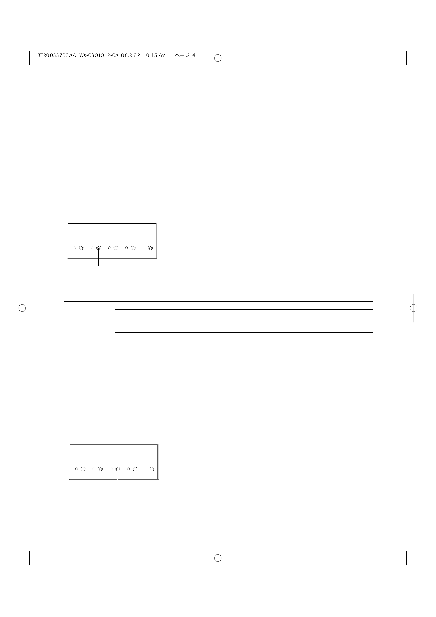
● Vehicle Detector BEEP DAY/NIGHT
In the case of Double Drive-Thru configuration, it is possible
to select the Vehicle Detector Beep tone to be heard when a
customer approaches the menu board.
Day/Night setup can be made by button operation at the
front panel of this unit.
When the Day mode is set, the Beep Day/Night indicator of
the center module will light in yellow. When the Beep
Day/Night button is pressed, the Night mode is assumed
and this indicator will disappear.
DAY/NIGHT
Vehicle detector Order Taker and All-in-One Headset
Lane A is ON Lane B is ON A B
DAY
b
– Beep A –
–
b
– Beep B
bb
Beep A Beep B
NIGHT
b
– Beep A Low level Beep A
–
b
Low level Beep B Beep B
bb
Beep A +
Low level beep B (*1)
Beep B +
Low level beep A (*2)
*1: When you press the button T1, the beep will change to low level beep B only.
*2: When you press the button T1, the beep will change to low level beep A only.
● Outside Speaker Level DAY/NIGHT
The Outside Speaker level can be set up.
Day/Night setup can be made by button operation at the
front panel of this unit.
When the Day mode is set, the Outside SP Level indicator of
the center module will light in yellow. When the Outside SP
Level button is pressed, the Night mode is assumed and
this indicator will disappear.
DAY mode: Normal level
NIGHT mode: 50% level (Attenuation)
Note:
• If POS Remote is set for ON, you have to note that no
button operation of the Outside Speaker Level is possible at the center module.
SPEED
TEAM
OPERATIONAL SETTING
BEEP
DAY/NIGHT
ON:DAY
OUTSIDE
SP LEVEL
ON:DAY
V/DET
OVERRIDE
T/P
RELEASE
Vehicle Detector Beep DAY/NIGHT Button
SPEED
TEAM
Outside Speaker Level DAY/NIGHT Button
OPERATIONAL SETTING
BEEP
ON:DAY
OUTSIDE
SP LEVEL
ON:DAY
DAY/NIGHT
V/DET
OVERRIDE
T/P
PELEASE
15
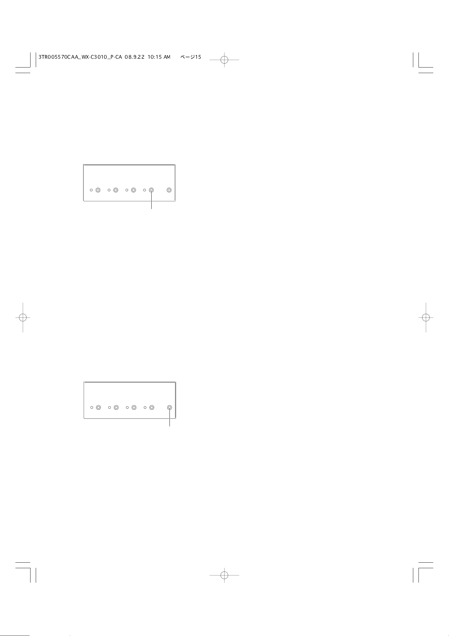
● Vehicle Detector Normal/Override On
The Vehicle Detector operation can be set up.
Normal/Override On setup can be made by button operation
at the front panel of this unit.
When the Override On mode is set, the V/D Override indicator of the center module will light in yellow. When the V/D
Override button is pressed, the Normal mode is assumed
and this indicator will disappear.
NORMAL: The vehicle detector turns on only when a vehicle
is detected at the menu board. When the detector turns
on, a beep tone is heard in the headset. When the Talk
button is pressed on the Order Taker or All-in-One
Headset side, the Outside Speaker and the Outside
Microphone are turned ON at the menu board.
When the vehicle leaves, the vehicle detector turns off.
When setting the normal position, Auto Talk Lock mode
is enabled.
OVERRIDE ON: The vehicle detector is always turned on.
When setting the override on position, Auto Talk Lock
mode is invalid.
● Talk/Page Release
In Talk or Page mode, any talk is temporarily interrupted at
the headset (Order Taker or All-in-One Headset).
Operation of Talk/Page Release is possible by button operation at the front panel of this unit.
Notes:
• If POS Remote is set for ON, you have to note that no
button operation of the Talk or Page Release is possible
at the center module.
• It is impossible to release the Talk or Page mode of the
All-in-One Headset or Order Taker in the manager
mode.
SPEED
TEAM
OPERATIONAL SETTING
BEEP
ON:DAY
OUTSIDE
SP LEVEL
ON:DAY
DAY/NIGHT
V/DET
OVERRIDE
T/P
RELEASE
Vehicle Detector Normal/Override On Button
OPERATIONAL SETTING
BEEP
ON:DAY
OUTSIDE
SP LEVEL
ON:DAY
V/DET
OVERRIDE
T/P
RELEASE
SPEED
TEAM
DAY/NIGHT
Talk/Page Release Button
16
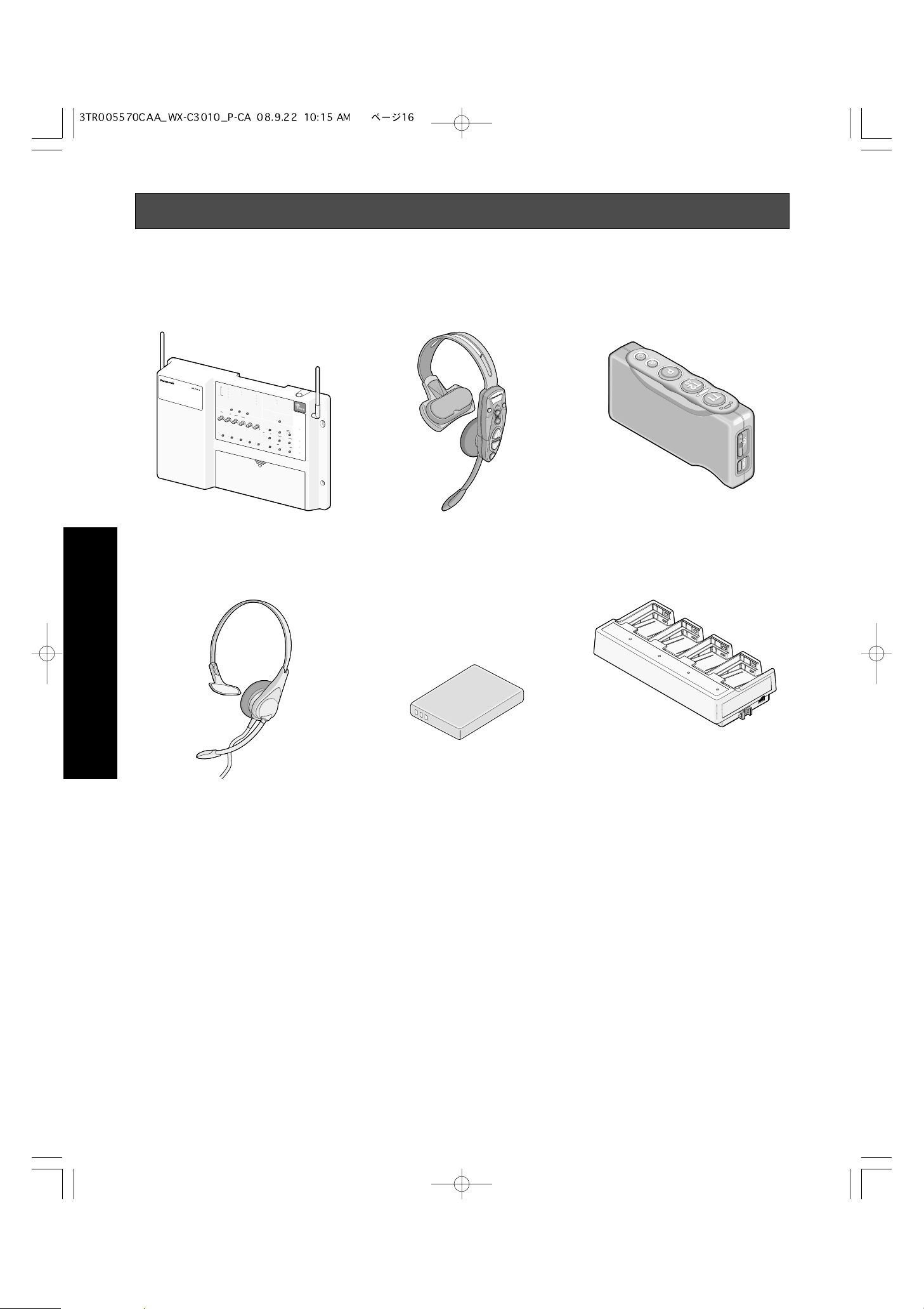
Panasonic WX-C3010 Series System Parts and Accessories
Note: Illustrations may differ from actual products.
■ Center Module
WX-C3010
■ All-in-One Headset
WX-H3050
■ Order Taker
WX-T3020
■ Headset
WX-H3027
■ Battery
WX-B3030 (1UF653450R-MDSP)
• Only used for WX-H3050 and WX-
T3020
• WX-B3030 and 1UF653450R-
MDSP are same models.
■ Battery Charger
WX-Z3040
Installation & Connections
AUX
I
N
A
E
C
UX
H
O
CA
T
A
N
C
L
SP
ELL
K
E
R
D
N
PA
R
D
L
G
U
EV
E
A
L
E
LA
L
N
E
R
LA
E
BE
D
NE
E
P
S
M
Y
A
E
E
X
L
L
E
L
O
C
W
T
M
GR
P
D
T
O
E
E
S
L
E
E
N
R
PHO
L
E
OW
M
OF
O
F
I
N
S
T
A
L
L
P
R
EV
O
UT
S
I
DE
SP
M
I
C
O
P
ERA
SPE
E
T
D
I
T
E
A
BE
M
E
P
DA
Y
/
N
I
G
HT
O
N:
DA
Y
N
T
E
E
CO
OF
N
F
T
TX
R
O
POW
L
O
UT
E
R
S
Y
S
T
E
M
S
E
T
T
IN
G
S
E
L
N
E
XT
I
D REG
AUX
S
P
O
N
A
L
S
O
UT
S
I
D
SP
L
E
VE
O
N:
DA
IS
T
R
A
T
I
O
BE
M
I
C
E
T
T
IN
G
E
V/
L
DE
O
VER
Y
N
E
P
P
O
S
AUDI
O
GREE
O
P
N
O
T
E
W
R
E
R
S
T
A
RT
DE
L
A
Y
REC
S
E
L
E
CT
1
2
T
V
O
L
UM
R
T
/
I
DO
P
DE
E
W
RE
N
L
E
A
S
TAL
E
K
UP
H
E
A
DS
E
PL
T
A
Y
BA
PAGE
CK
DE
S
T
I
N
A
T
AUX
I
O
N
HE
VEH
A
DS
I
C
E
LE
T
D
ETE
C
TOR
WX-H3050
17
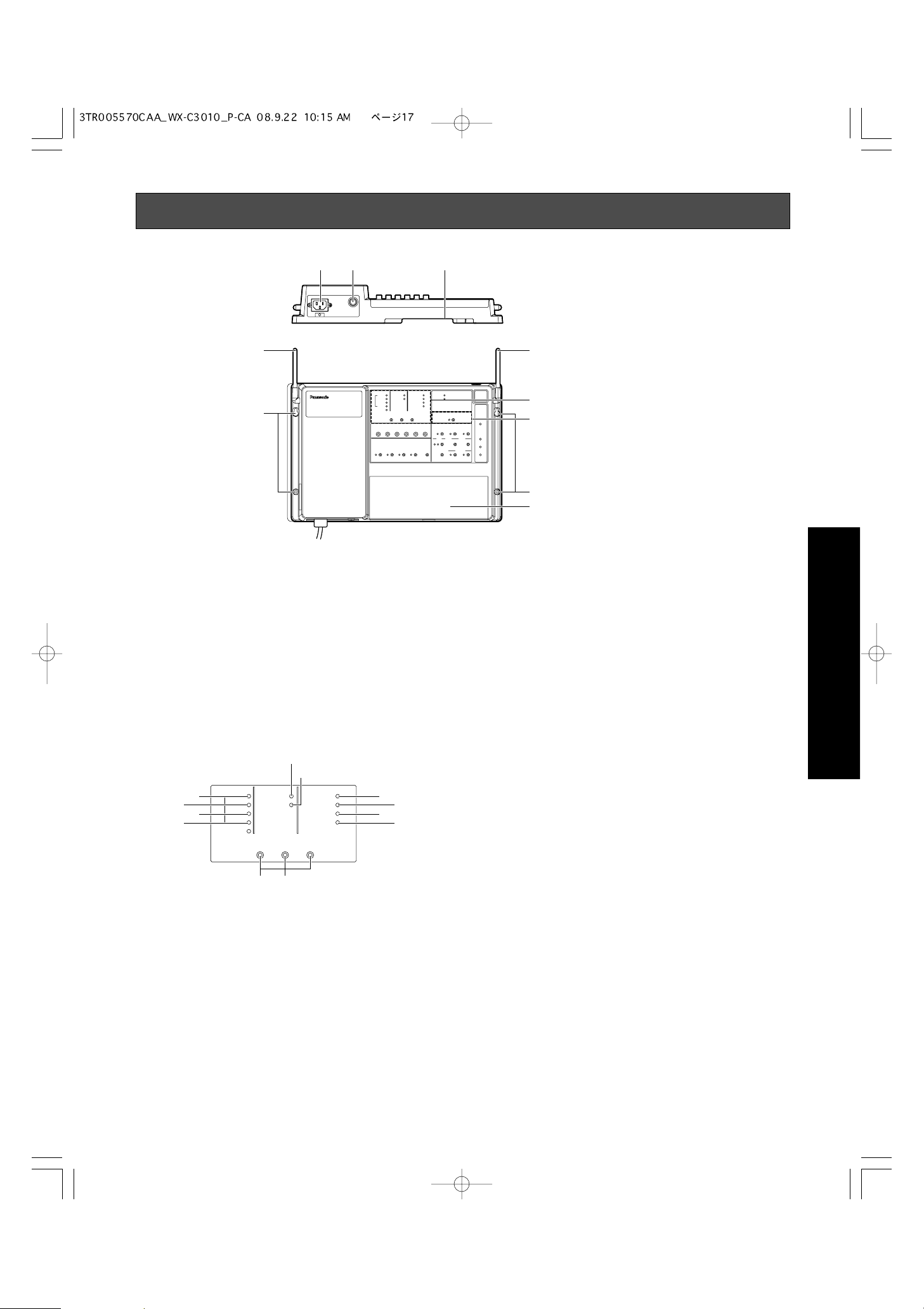
Major Operating Controls and Their Functions
q AC Inlet
w Power On/Off Switch
e Through-hole
r Antenna
t Mounting Hole
y Terminal Board Cover
[INSTALLED SYSTEM SETTING]
The following buttons should be used by qualified service
personnel or system installers only.
u PREV/NEXT Button (INSTALL SYSTEM SETTING,
PREV/NEXT)
These buttons select the system setting items.
i Select Button (SEL)
This button selects set value of the system setting items.
o Auxiliary Input On/Off Indicator (Green) (AUX IN)
This indicator is toggled ON when the auxiliary input
sound is provided through the auxiliary speaker.
q w e
!
!0 Talk On/Off Indicator (Green) (TALK)
This indicator is toggled ON when the communication
between store personnel and a customer is provided
through the auxiliary speaker.
!1 Page On/Off Indicator (Green) (PAGE)
This indicator is toggled ON when the communication
among store personnel is provided through the auxiliary
speaker.
!2 Beep On/Off Indicator (Green) (BEEP)
This indicator is toggled ON when a beep is provided
through the auxiliary speaker.
!3 Echo Canceller Effect Level Control Indicator (ECHO
CANCELLER)
The removal rate of the echo canceller, intended to eliminate the echo returned from the menu board, is set up.
OFF: Off
LOW: Green
MID: Yellow
HIGH: Red
!4 DNR Effect Level Control Indicator (DNR LEVEL)
The more the noise is reduced, the lower the sound
quality will be. The table of the page 27 relationship
between noise reduction level and quality.
OFF: Off
LOW: Green
MID: Yellow
HIGH: Red
!5 Dual lane On/Off Indicator (Green) (DUAL LANE)
When the TANDEM operation at the double drive-thru,
set to ON.
Installation & Connections
r
t
r
INSTALLED SYSTEM SETTING
ID REGISTRATION
t
y
o
!0
!2
!1
AUX
SP
ECHO CANCELLER
AUX IN
TALK
PAGE
BEEP
INSTALL SYSTEM SETTING
PREV
DNR L
RED M
YELLOW MD
GREEN
L
OFF OFF
3
!4
DUAL LANE
E
VE
L
LANE SELECT
A
X
POS REMOTE
OW
TX POWER
NEXT
SEL
ui
!5
!7
!6
!8

18
!6 Lane select Indicator (Red/Green) (LANE SELECT)
Select the lane A or B at the double drive-thru.
Red: Selected Lane A
Green: Selected Lane B
!7 POS Remote Control Indicator (Green)
(POS REMOTE)
This item selects the POS remote control On and Off.
OFF: POS Remote OFF
ON: POS Remote ON
!8 TX Power Indicator (Green) (TX POWER)
This item selects the transmit power Normal and
Attenuation.
OFF: Reduce Power (25 %)
ON: Normal Power
[ID REGISTRATION]
!9 ID Registration Indicator (Red) (ID REGISTRATION)
This indicates that while the ID registration.
@0 ID Registration Button
Pressing this button for two second or more will turn the
ID registration mode On. When you push this button
again, it returns to a normal mode.
ID REGISTRATION
!9
@0

19
Installations/Connections
■ Installation procedures
Preparations (Refer to page 19.)
Installation of center modules on the wall (Refer to page 19.)
Wiring to the center modules (Refer to page 20.)
ID registration for follower units (Refer to page 25.)
[System Setup]
Installed System Setting
(Refer to page 26.)
Adjustments to adequate sound levels
■ Preparations
This Center Module is designed to be mounted on a wall directly. Please be advised of the following:
• Procure 4 mounting screws according to the material of the installation area.
In this case, wood screws and nails should not be used.
Recommended screw: M4 x 25 mm
• Required pull-out capacity of a single screw/bolt is 118 N {12 kgf} or more.
• If a wall board is too weak to support the total weight, the area shall be sufficiently reinforced.
■ Installation of center modules on the wall
Fix the center module directly to the wall, using the prepared 4 screws. (These screws are not furnished.)
386 mm {15-1/4"}
AUX
I
N
AUX
ECHO CANCELLE
T
A
L
SP
K
R
D
NR LE
PA
DUA
G
E
V
L
E
L
L
A
N
E
R
L
ED
BE
A
N
E
E
P
M
S
Y
A
E
E
X
L
L
E
L
OW
CT
MD
GR
P
T
O
E
E
N
L
OF
F
OF
I
N
S
T
A
L
L
S
P
R
EV
OU
T
S
I
D
E
S
P
M
I
C
SP
O
P
E
SP
RA
E
E
T
D
I
O
N
T
E
A
BE
M
E
P
D
A
Y
/N
I
OU
G
H
T
SP L
O
N:
DA
Y
O
E
S
L
E
RE
P
OW
F
Y
S
T
E
S
E
L
AU
X
A
L
T
S
E
N:
DA
H
MO
ON
T
E
E
C
ON
T
T
R
X
O
P
L
O
OU
W
ER
M
S
M
I
C
S
E
T
T
I
D
E
VE
L
Y
T
E
T
T
I
N
G
N
E
X
T
I
D
R
E
G
I
S
T
R
A
T
I
O
B
E
E
P
AU
I
N
G
V/DE
T
O
V
ER
R
ID
E
P
R
N
P
O
S
D
IO
G
RE
ON
P
E
O
T
E
W
R
E
R
S
T
A
R
T
D
E
L
A
Y
R
EC
S
E
L
E
C
T
1
2
VOLU
T
M
/P
D
E
OW
N
E
L
E
A
S
E
H
E
PL
TAL
K
U
P
A
DS
E
T
A
Y
BACK
P
AGE
D
E
S
T
I
N
A
T
AU
I
ON
X
H
E
V
AD
E
HICLE
S
E
T
D
ETE
C
T
OR
Use the dents at the top or bottom of
center module for wiring. When routing
wires through the wall, make the
openings according to the dimensions
in this illustration.
386 mm {15-1/4"}
225 mm {8-7/8"}
150 mm {5-7/8"}
25 mm {1"}
60 mm
{2-3/8"}
150 mm {15-7/8"}
20 mm
{3/4"}
20
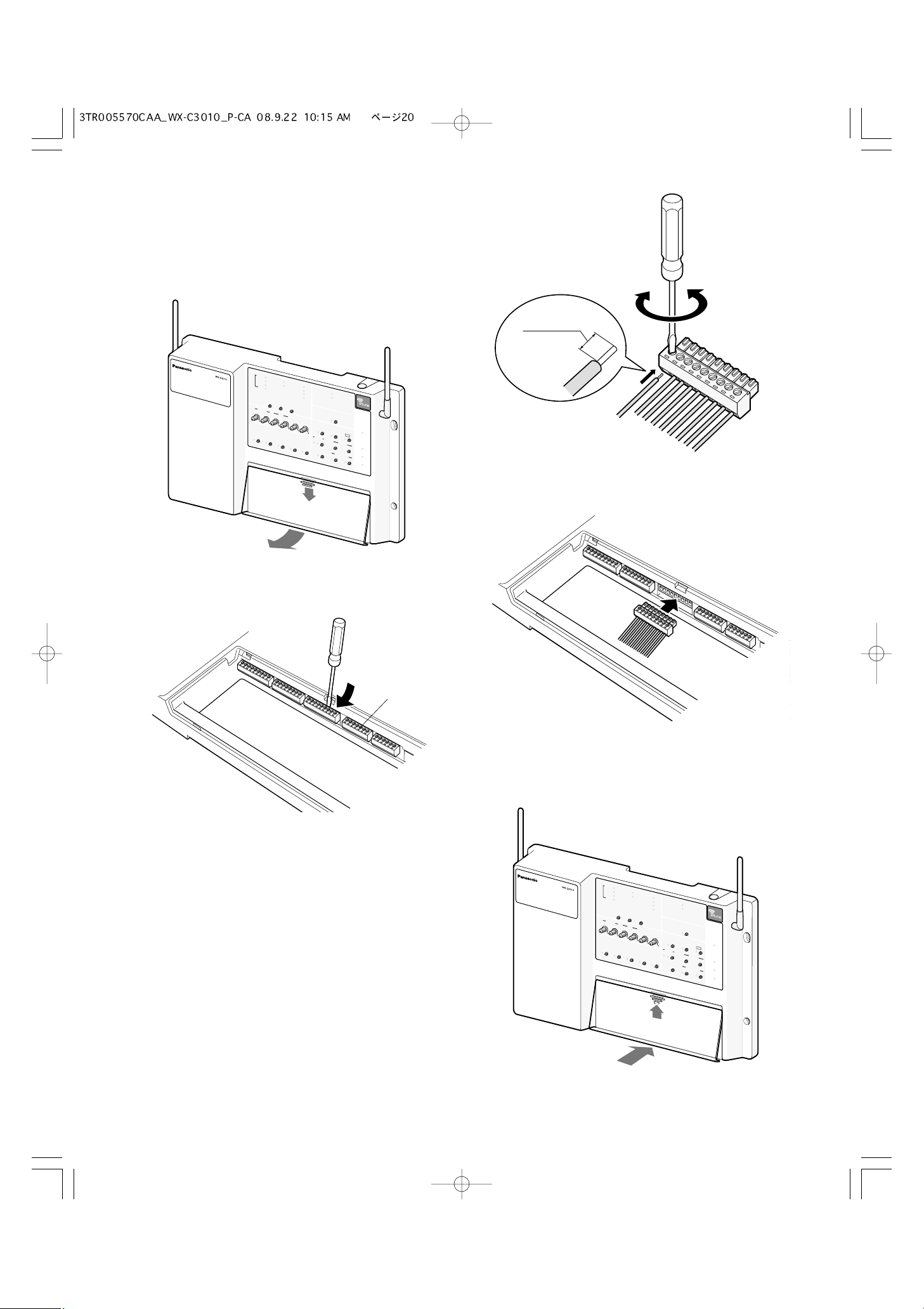
■ Wiring to the center modules
1. Remove the terminal cover.
Slide the front cover downwards by pressing its arrowmarked part and pull the lower side of the cover toward
you.
2. Insert a “minus” screwdriver in the slot as illustrated and
remove the terminal socket from the main unit.
3. Connect the wiring material to the terminal socket.
Use the “minus” screwdriver and loosen the screw located on the upper surface of the terminal socket.
Peel off the sheath from the tip of the wiring material and
insert the cable tip in the terminal socket.
Firmly tighten the loosened screw by means of the
“minus” screwdriver.
Repeat the above-mentioned same procedure for each
terminal.
Notes:
• Process the wires according to the following:
Recommended wire type: AWG 28 - 16 (Do not use
soldered wires.)
Length to be stripped: 7 mm ± 1 mm {9/32" ± 1/16"}
Diameter of screw: ø 2 mm {3/32"}
• Check to be sure that the wires are securely connected.
4. Mount the cabled socket on the main unit.
Note: Insert the socket firmly into the main unit.
5. Slide the front cover from the bottom and mount it on the
main unit.
Note: Surely attach the front cover to the main unit.
7 mm ± 1 mm
{9/32" ±
1/16"}
AUX IN
AUX
ECHO CANCELLER
TALK
SP
DNR L
PAGE
DUAL LANE
E
VE
L
RED
LANE SEL
BEEP
M
Y
A
E
X
L
ECT
L
OW
M
GRE
POS REMOTE
D
E
N
L
OW
OF
F
O
F
F
I
N
S
T
A
L
L
S
Y
S
PREV
SEL
O
UTSIDE
S
P
MIC
A
U
S
P
O
P
ER
S
P
EED
A
T
I
ON
TEAM
A
B
L
EEP
D
AY
/
NIG
O
U
HT
TSIDE
S
O
P
N:
LEVEL
DAY
O
N:
TELEPHONE
CONT
TX POWE
R
O
L OUT
R
T
E
M
S
E
T
T
I
N
G
N
E
XT
ID R
E
G
X
B
EEP
MIC
S
E
T
T
I
N
G
V
/
D
ET
O
V
E
RR
D
AY
I
I
S
T
R
A
T
I
POS
A
U
DI
T/
D
E
RELEASE
ON
O
GR
E
O
N
SELE
C
1
2
P
HEADSET
P
LAYB
P
E
O
T
E
W
R
E
R
START
D
ELAY
R
E
C
T
V
O
L
U
ME
D
O
W
N
T
A
LK
U
P
A
P
A
C
DESTINATI
G
K
E
A
O
U
N
X
H
EADSET
V
E
H
IC
L
E
DET
E
C
TOR
Terminal socket
AUX IN
AUX
ECHO CA
T
A
N
CE
L
SP
K
L
LE
R
DNR LEVEL
PA
DUA
G
E
L
L
A
N
E
RED
L
BE
A
N
E
E
P
M
S
Y
A
E
E
X
L
L
ECT
L
OW MD
GRE
P
T
O
E
S
E
N
L
OW
OF
F
OF
F
I
N
S
T
A
L
L
S
Y
S
T
E
P
R
EV
S
E
L
O
UTS
I
DE
S
P
M
I
A
C
U
X
S
P
O
P
ER
S
P
E
A
ED
T
I
ON
T
E
A
A
B
L
M
E
S
EP
D
A
Y
/
N
I
O
G
U
HT
T
S
I
D
S
O
P
N:
L
DA
E
VE
Y
O
N
:
D
A
L
E
RE
PHON
M
OT
E
E
CON
T
T
R
X P
O
L
O
OUT
WE
R
M
S
E
T
T
I
N
G
N
E
XT
ID R
E
G
I
S
T
R
A
T
I
B
E
M
EP
I
C
P
O
A
U
DI
E
T
T
I
N
G
E
V
/
L
D
E
T
O
V
E
R
R
T/
I
D
Y
E
RE
L
E
ON
S
O
GR
E
O
N
S
E
L
E
C
T
1
2
P
A
S
E
HE
AD
P
L
A
Y
B
P
E
O
T
E
W
R
S
T
A
R
T
D
E
L
A
Y
R
E
C
V
O
L
U
M
D
E
O
W
N
T
A
L
U
P
S
E
T
A
C
P
A
D
K
G
E
S
T
I
N
A
T
A
I
O
U
N
X
H
E
V
ADS
E
H
ICLE
E
T
DE
T
E
CTO
E
R
K
E
R
21
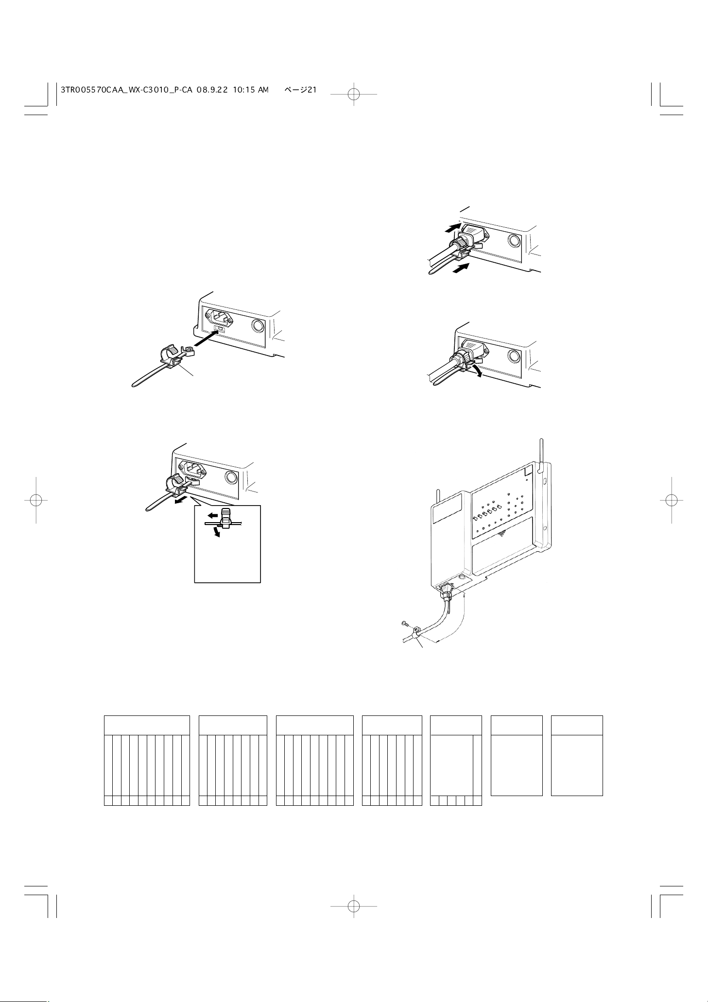
3. Insert the power plug into the power cord inlet.
4. Push the holder forward until the holder touches the
power plug.
5. Lock the holder.
6. Clamp the AC cable with the provided clamp, and
secure the AC cable clamper to the wall by fastening the
screws.
AUX SP + (8Ω)
CONNECTOR 1
ORDER INTERFACE
1
AUX SP GND2
OUTSIDE SP + (8Ω)3
OUTSIDE SP GND4
OUTSIDE MIC +5
OUTSIDE MIC –6
OUTSIDE MIC GND7
V/DET 1 IN8
COM9
V/DET 2 IN10
SPEED TEAM
CONNECTOR 3
POS INTERFACE
1
TALK LOCK RELEASE2
MANAGER SELECT3
PAGE SELECT4
IN COM5
POS AUDIO IN6
POS AUDIO GND7
POS AUDIO OUT8
POS AUDIO GND9
V/DET 1
CONNECTOR 4
POS INTERFACE
1
V/DET 22
TALK3
PAGE4
OUT COM5
NIGHT MODE6
OUTSIDE SP LEVEL7
CONNECTOR 5
1
2
N.C
N.C
3
4
5
COM6
CONNECTOR 6
MAINTENANCE
DOUBLE-DRIVE-THRU
Use a LAN cable
with the shield type
CONNECTOR 7
DDT INTERFACE
AUX MIC +
CONNECTOR 2
ORDER INTERFACE
1
AUX MIC –2
AUX MIC GND3
AUX MIC PTT4
COM5
DEVICE CONTROL6
COM7
N.C8
● Refer to the following lists attached on the inside of the terminal cover to make connections.
■ Clamping the Power Plug and
Power Cord
Important:
Surely clamp the power plug to this center module and
screw the AC cable to the wall using the provided AC
cable clamper.
1. Insert an AC cable holder into the hole under the AC
inlet.
2. Slide the holder to the backward by pushing down the
clamp lever.
3
150 mm - 200 mm
{5-15/16" - 7-7/8"}
AC cable clamper
Screw size: M4 x 25 mm
Pull-out capacity: 12 kgf
AC cable holder
Slide the holder
to the backward
by pushing down
the lever.
4
 Loading...