

Page 1

TRIAD Boiler Systems, Inc.
Series 8900 SH
Space Heating Control Panel
Operation and Installation Manual
Printed in USA. 1/12/04
TRIAD Boiler Systems, Inc.
West Chicago, IL 60185
Phone: 630-562-2700
Fax: 630-562-2800
www.triadboiler.com
Page 2

Series 8900SH Control Panel Operation And Installation Manual
TABLE OF CONTENTS
Section
Introduction 1
Sequence of Operation 2
Entry Codes 3
Sensor Calibration 4
Sensor Troubleshooting 5
Monitoring Codes 6
Error Codes 7
Explanation of Entry Codes 8
Fine Tuning the Heating System 9
Troubleshooting 10
Page 3

Series 8900SH Control Panel Operation And Installation Manual
SECTION 1: INTRODUCTION
This manual explains the operation, installation and control of TRIAD Boilers using the
Series 8900 Microprocessor Control Panel. This manual provides information needed to
operate the panel and to f ine-tune the boiler system de pending on the requirements of the
structure that requires heating.
We have taken care to make this manual as easy to understand as possible, and to
anticipate common questions that might be asked. If we missed something along the way,
please feel free to call us or your TRIAD Manufacturer’s Representative with ideas and
suggestions.
INSTALLATION PROCEDURES:
The Series 8900SH Control Panel requires 120V A.C., 5 AMP, 60 Hz single phase to
operate. Service wiring should be run in an approved manner using black and white wire.
Minimum wire size shold be 14 guage or as local code requires.
After running the service wire to the pane l, connect to the fuse block and neutral terminal,
which is marked. Be carefull that the panel is not mounted in an area that could experience
temperatures above 125°F.
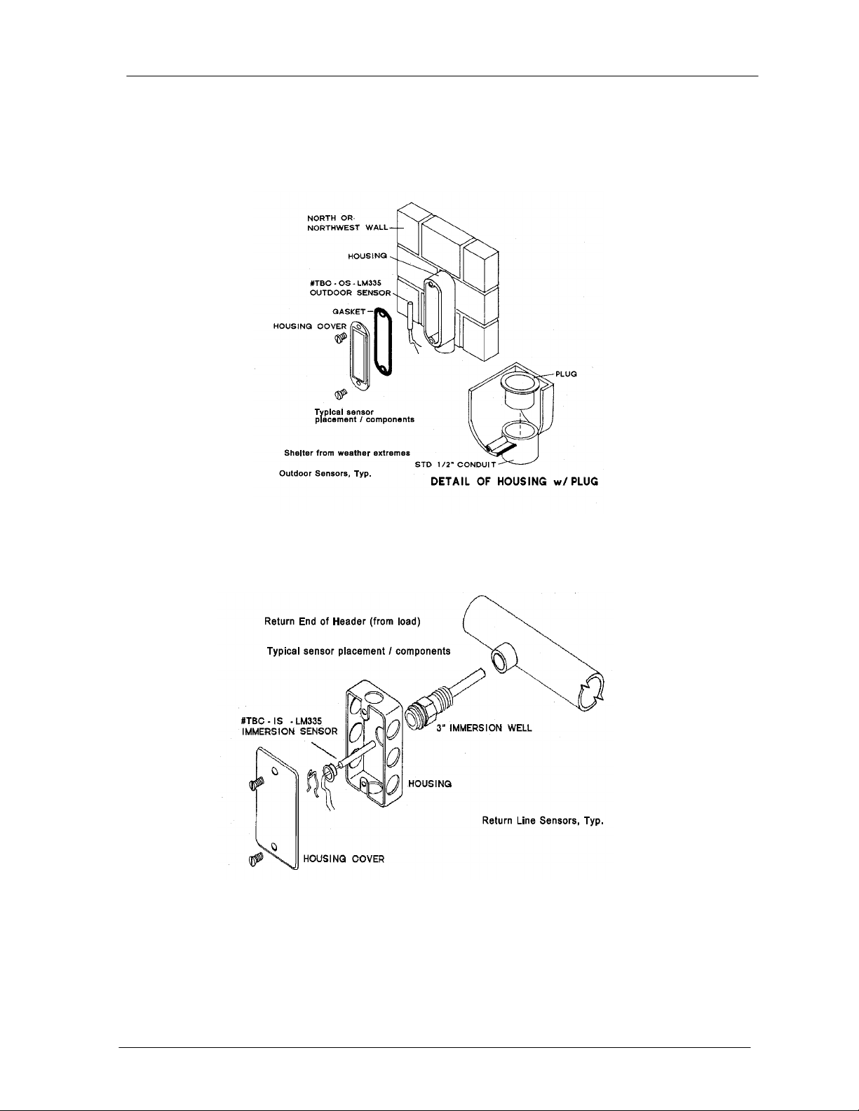
Mounting the Outside Sensor:
The outdoor sensor is to be mounet on the North or Northwest outside wall of the building.
The sensor should be mounted no less than twelve feet above the ground. In a high-rise
installation, when the equipment room is on the top floor, install the sensor as close as
possible to the panel with it still on a North wall. Caution – Do not mount the sensor near a
heat source such as an air handler or lighting fixture.
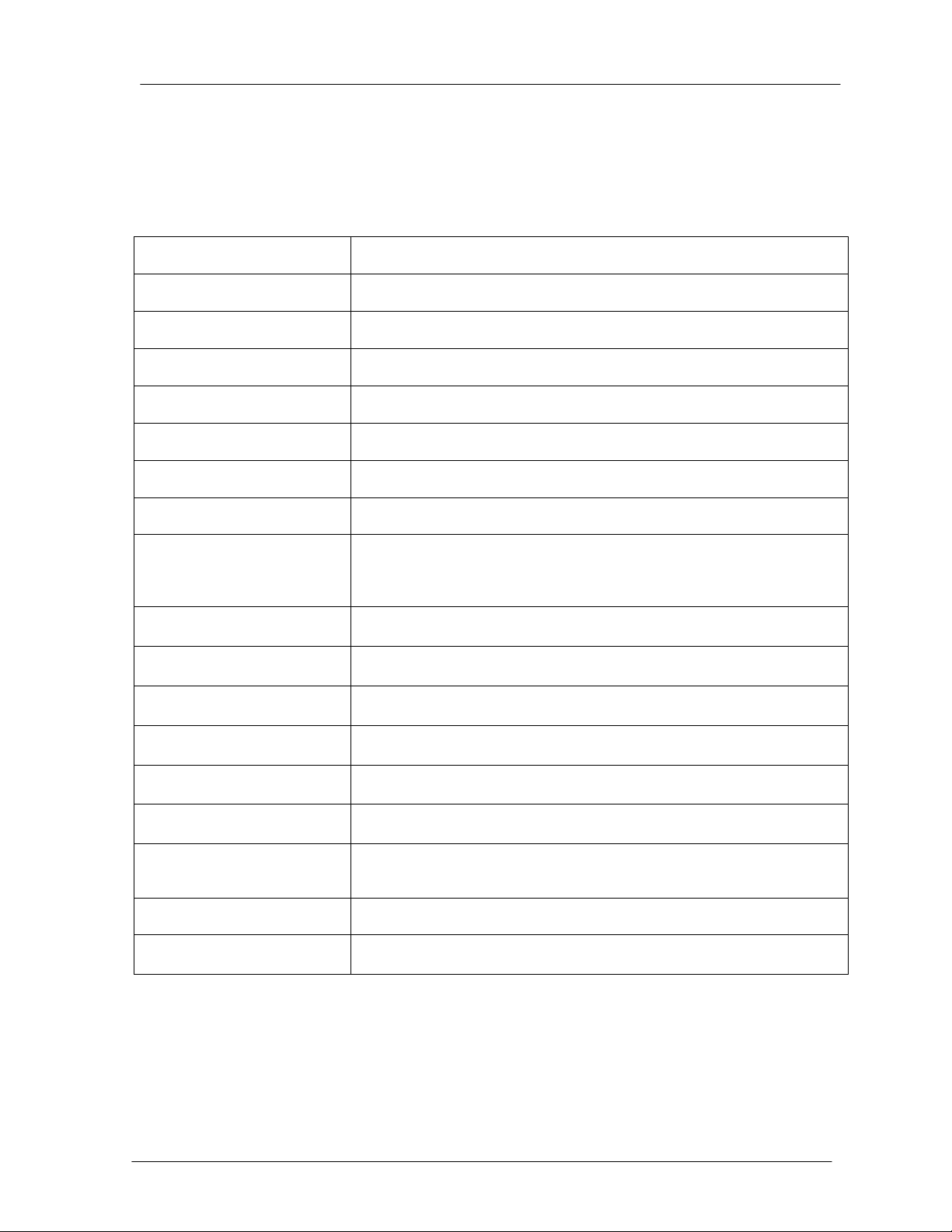
Mounting the Return Line Sensor:
The immersion sensor is to be installed in the return side on the Primary Main of the boiler
system, at least 12 inches away from the nearest boiler.
Use 18 gauge solid copper wire between the senors and the control panel.
Use 18 gauge or heavier coded thermostat wire to connect the low voltage terminals
between the boiler and the control panel.
TRIAD recommends that the boilers be numbered. The terminal strip in the panel is
prenumbered at the factory. Direction of flow through the Primary Main should be noted .
The #1 boiler is at the “Supply End” of the Primary Main. The last boiler in the series is on
the “Return Side”.
Connect each boiler to the control pane l ensuring that each boiler number is connected to
the corresponding number in the control panel. Maintain polarity! This means all first
Section 1 Introduction And Specifications
Page 4

Series 8900SH Control Panel Operation And Installation Manual
terminals of each pair should be connected to the same terminal in each boiler control
center. Follow the drawing and wiring information carefully!
KEYPAD WITH ENTRY PROCEDURES
All functions of the Control Panel are activated through the use of two-digit Entry Codes via
a simple keypad, which operates as follows:
1 2 3
4 5 6
7 8 9
0 #
∗
1. Press the appropriate two digit Entry Code.
2. W ait for the Entry Code in the display to begin flashing.
3. Enter the desired temperature, value code, etc.
4. Press the pound sign # to save the displayed entry.
Press the star sign ∗ to abort an unwanted entry to prevent it from being saved and to revert
back to the last display code viewed. To discontinue the entry procedure, press the star sign
to start over.
STARTUP PROCEDURES:
To bring the Series 8900SH Control Panel online, the following three steps must be
completed:
1. Unlock the keypad using code 61. (See Section 8)
2. Enter the code settings through the keypad. (See sections 3 and 8.)
3. Calibrate the sensors. (See Section 4).
System shut down and start-up should be done through the keypad only, (by using Code
62) and NOT by shutting off power to the control panel. If the power to the panel is off for
more than 30 days, all control settings will be lost. In the event of temporary power loss the
panel has two built-in rechargeable batteries that will maintain the settings for up to 30
days. THE FIRST TIME THE PANEL IS TURNED ON THE BATTERIES WILL REQUIRE 48
HOURS TO TRICKLE CHARGE.
Code 61 is used to lock or unlock the system. Lock the system when you are completed
with the initial settings, or any time you change the settings. The system display readings
are always available, even with the keypad locked.
Section 1 Introduction And Specifications
Page 5

Series 8900SH Control Panel Operation And Installation Manual
In the event of power loss or damage to the control panel the boilers will revert to self
control. At that point each boiler will cycle on and off according to its high limit control.
TRIAD recommends that in this situation the high limits be set at approximately 180°F.
Section 1 Introduction And Specifications
Page 6

Series 8900SH Control Panel Operation And Installation Manual
WIRING DIAGRAM
Section 1 Introduction And Specifications
Page 7
Series 8900SH Control Panel Operation And Installation Manual
OUTDOOR AND RETURN WATER LINE SENSORS:
Section 1 Introduction And Specifications
Page 8
Series 8900SH Control Panel Operation And Installation Manual
SERIES 8900SH SPECIFICATIONS:
Input Voltage
Avg. Power Consumption
Battery Protected Memory
CPU
Time Clock
Operating System Memory
Serial Interface
Sensor Input Channels
Sensor input Range
Sensor Accuracy
Sensor Type
Output Channels
9.8 vac, 50/60 Hz, max input 35 vac with transient/surge protection
3VA
8K RAM
Industry standard Z80, 4MHz
Internal crystal based clock
8K EPROM
1200 Baud standard TTL signal level. Can be interfaced with modem
or direct connect to IBM compatible PC
Six
Voltage input of 1.9VDC is read at a value of –55 by the controller.
Voltage input of 3.1VDC is read as a value of 200. If an input is
shorted to common, the controller will read –40 at the input. If input
is open, the controller will read 230.
Within + or – 1 degree Fahrenheit
Solid-state linear sens ing
Up to 24
Output Capacity
Relay Type
All Other Components
Wiring
Batteries
Display
30VA, 24VAC
Coil 12VDC / “Dry Contact”
5VDC
Multiconductor 18 AWG thermostat wire is recommended to wire
sensor inputs and control outputs. Maximum length of wire from
control panel to sensor is 300 feet.
Two 1.2V sealed nickel-cadmium rated at 720 hrs. Standard charge
15 hrs at 18mA.
Light Emitting Diodes
Section 1 Introduction And Specifications
Page 9

Series 8900SH Control Panel Operation And Installation Manual
GLOSSARY:
Entry Codes: The set of two digit numbers that allow the operator to interact with the
control panel.
Error Code: A code shown on the display that indicates a problem exists either in the
sensors or in the computer itself.
Fine Tuning: Utilizing certain codes concerned with the boiler run time and the boiler
staging to carefully "size" the output to the building to obtain the highest efficiency possible.
High Limit: A control mounted near the top of the boiler that shu ts down the main f lame of
the burner if the boiler temperature exceeds the high limit setting.
Manual Override: When Code 63 is used to manually override the control panel.
Potentiometer: An electronic device used to adjust the sensor temperatures.
Program: A set of commands that tells the computer which calculations to carry out.
Ratio Control: The control that allows the operator to vary the Return Water Line
temperature in relation to the drop in outside temperature.
Relay: An electromechanical device that opens or closes a current path on demand.
Sensor: A device used with the control panel to measure relative heat and cold.
Outside Temperature Shutdown: The pre-selected temperature that, when reached, shuts
the boiler system off.
Stage: The position of a boiler in the firing sequence.
Supply Water Line: The supply water line is the line that provides heated water from the
boilers to the building.
Section 1 Introduction And Specifications
Page 10

Series 8900SH Control Panel Operation And Installation Manual
LIMITED FIVE -YEAR FULL TERM WAR RA NT Y
The Manufacturer warrants the equipment described as the Series 8900 Control Panel to
be free from defects in material or workmanship under normal use and service. The
Manufacturer's obligation und er this warranty shall be limited to repairing or replacing any
part of said pan el, which the Manuf acturer’s examination shall disclose to its satisfa ction to
be thus defective, for a period of One (1) Year after date of original installation provided
proper evidence of such installation is recorded at the factory and installation is in
accordance with TRIAD design.
The Manufacturer further agrees that if the Series 8900 Circuit Board(s) shall be
disclosed to the manufacturer's satisfaction to be defective u nder normal use and service
during a period of Five (5) Years after date of original installation, a replacement Circuit
Board will be f urnished the owner f ree of charge, exclusive of any applicable federal, state
or local taxes.
All repairs and/or replacements furnished shall be F.O.B. TRIAD's factory. The
Manufacturer shall not be liable for freight, drayages installation and/or other labor costs
and any other costs or expenses involved with direct replacement of the defective parts.
Defective part failures covered by this warranty should be promptly reported to the
Manufacturer. This Warranty voided if Panel sustains an excessive surge in primary or
secondary voltage.
This Warranty is in lieu of all other warranties expressed or implied and of all other
obligations or liabilities on the part of the Manufacturer, and the Manufacturer neither
assumes nor authorizes any other person(s) to assume for it any obligation or liability in
connection with the sale of said equipment or any part thereof. This Warranty will not apply
to said e quipment or any p art thereof which has been subject to any accident, n egligence.
misapplication, alteration, abuse or misuse. Nor do es it apply outside the boundaries of the
United States.
Section 1 Introduction And Specifications
Page 11

Series 8900SH Control Panel Operation And Installation Manual
SECTION 2: SEQUENCE OF OPERATION
All functions of the Control Pane l are activated through the use of two-digit Entry Codes that
provide instruction to the panel. These codes are explained in more detail in Sections 3 and 8.
The sequence of operation is best explained through the following example:
Assume a six boiler TRIAD system heating an office building that is empty at night and on
weekends, an average outside temperature of 70°F, with an expected night temperature of
35°F.
The control panel is on and controling the building heat. Through Entry Codes it has been
instructed as follows:
Turn the heat on when the outdoor temperature d rops be low 60°F and off when it rises above
60° F.
Maintain a minimum Return Water Line temperature of 100°F, with a starting outdoor
temperature of 60° F.
The manual Reset Ratio is set on Automatic.
The rate of system change factor is set at .10.
The boilers will fire in a sequence of 1, 2, 3, 4, 5, 6, and boiler number 1 is the lead boiler.
At 6:00 pm the temperature will automatically be set back by 5°F, with a return to normal
temperature occuring 6:00 am.
As the outside temperature gradually drops from 70 °F to 60°F, the control panel prepares to
bring on heat. The decision has been made for the boilers to fire in a sequence of 1 through 6,
so as the outdoor air temperature drops below 60°F, the control panel calls for the number 1,
or lead boiler, to fire. As boiler 1 fires it begins to add heat to the return main. Because it is the
designated lead boiler, n umber 1 will continue to f ire intermittently while hea t is called f or. The
lead boiler shuts off when the required Return Water Line temperature is reached (determined
with code 14) and f ires again when the Return Water Line temperature has d ropped 2°F. This
allows all the cycle time and the attendant wear and tear to be confined to the lead boiler. Any
boiler can be designated the lead at any time.
As the temperature outside continues to drop, the control panel notes that the Return W ater
Line temperature has not reached the 100°F it must maintain, so it calls for the number 2 boiler
to fire. However, bef ore it can bring on the number 2 boiler it checks to make sure that the
other instructions entered into the control panel are being satisfied. These are (i) the rate of
system change f actor, (ii) the required Return W ater Line temperature, and (iii) the calculated
Reset Ratio. W ith this information t he panel can fire the other bo ilers in a way that will most
efficiently satisfy the heating needs.
Section 2 Sequence of Operations
Page 12

Series 8900SH Control Panel Operation And Installation Manual
If the outside temperature continues to drop, then the calculated Reset Ratio (code 23) will be
activated. More heat will be required to maintain the building temperature. To determine ho w
much more, the control panel monitors (when in Automatic mode) the outdoor air temperature,
the current Return Water Line temperature, the design return water temperature, and the
design outdoor temperature. It then determines the Reset Ratio, which is simply a way of
calculati ng how much heat to add to the system to make up for heat loss. If the Reset Ratio is
set at 1:1.5 then for every 1°F the outdoor temperature drops, the Return Water Line
temperature will be increased by 1.5°F. It is possible to override the automatic mode and enter
your own Reset Ratio in code 23.
The next code that is monitored is the Rate o f Change Factor (code 24) which sets the speed
at which boilers are brought on line and off line. This rate of change f actor has a range of .01
to 2.00. The rate of change factor is a timer that counts from 0.00 to 99.00. W hen 99.00 is
reached, a boiler is brought on line or taken off line. The rate of change factor is important
because it allows for a b alancing of how much heat is increased against how much heat the
building naturally loses. The rate of change factor also allows you to determine how long each
boiler will run before firing the next boiler in line.
Assume it is now 7 :00 pm, the building is empty and dark, and three of the boilers have been
used to maintain the building heat. Because the control panel was set to lower the
temperature in the Return W ater Line at 7:00 pm, it directs one boiler to go of f line, allowing
the Return W ater Line temperature to fall the required 5 degrees. At 6:00 am the panel will
increase the Return Water Line temperature back to normal so the building will be warm when
the employees arrive.
An important feature of the Series 8900SH control panel is its ability to handle setback
recovery. The control panel starts monitoring the Return Water Line temperature and outdoor
temperatures 2 hours
fire the boilers. Instead of all the boilers firing simultaneously, the panel may only fire one
boiler, but allow it to run longer to save on fuel.
If heat was need ed in the building af ter 7:00 pm a simple keypad entry (code 81) will override
the setback. This set back override can be done in advance, or at the time the heat is needed.
Assume it is now early afternoon and the outdoor temperature continues to rise. Only two
boilers are need ed to maintain the building temperature. When the outdo or temperature rises
above 60° F, the control panel shuts the system down until the next time it's needed.
prior to the 6:00 am set point so it can calculate the most efficient way to
Section 2 Sequence of Operations
Page 13

Series 8900SH Control Panel Operation And Installation Manual
SECTION 3: ENTRY CODES
The control panel is operated by Entry Codes, which are simple two digit numbers that provide
the pane l instructions. However, bef ore entering any cod es, you should become familiar with
the features of the control panel.
The 8900SH h as a keypad and a set of 6 display LED’s. A code is entered by simply pressing
any of the two digits o n the keypad, which will then cause two LED’s on the far left to light up
in the order of the keys pressed. You must wait for the Entry Code in the display to begin
flashing before entering the desired temperature, value, code, etc.
The (∗) star key on the lower left of the keypad cancels any code you have entered. If the
wrong code is entered, simply press the (∗) key and start over.
IF THE PANEL DOES NOT POWER UP, OR THE RED DISPLAY LED’S ARE NOT ON,
REFER TO THE WIRING DIAGRAM AND INSTALLATION INSTRUCTIONS. ALSO, REFER
TO “SENSOR TROUBLESHOOTING” IN SECTION 5.
Below is a quick ref erence table showing the codes used to set up the control panel’s basic
operation. Do not be concerned that the codes are not listed in numerical order.
YOU MUST ENTER T HE CODES IN THE ORDER SHOWN BELOW, THEN CALIBRATE ALL
SENSORS CONNECTED TO THE CONTROL PANEL. MORE DETAIL ON EACH CODE IS
AVAILABLE IN SECTION 8.
CODE FUNCTION
60
62
63
65
66
This code starts the sequence for the “60” codes.
This code displays the System Mode, which tells us that the boiler system is either ready to
heat or is shut off. Press 62 then press 0 (for System Off) or 1 (for System On).
This code manually overrides the control panel to control the boilers directly. Press Code 62
first, and enter 0, then press Code 63 and enter the number of the boiler you want to fire.
This code allows for the panel to control the system primary pump. After entering code 65,
entering 0 shuts the pump off, entering 1 starts the pump, and entering 2 automatically
cycles the pump. In the automatic cycle mode, the pump starts and stops along with the
boilers according to the system shutdown outdoor temperature chosen in code 21. Please
note that the pump starter must be an Automatic Reset type.
This code controls the temperature setback feature. When 66 is entered, the display will
show 0 or 1. Press 0 to turn it off, or press 1 to turn it automatically on.
67
68
This code displays the 24 hour (military) clock. Press 67, enter the hour and minutes, and
press # to save.
This code displays the day of the week and the day of the month. Press 68, enter the day of
the week and press #, then enter the day of the month, 01 to 31, and press #.
Section 3 Entry Codes
Page 14

Series 8900SH Control Panel Operation And Installation Manual
69
20
21
22
23
24
This code displays the month and year. Press 69, then enter Month, 1 to 12, and the year,
01, 02, 03, etc. Then press #.
This code starts the sequence for the 20 codes.
This code stores the outside air temperature at which the heating system cycles off and on.
While the system can be set anywhere between 0° F and 120° F, TRIAD recommends a
setting of around 60° F. Press 21, enter the desired temperature, and the display will show
the setting. The system will now shut down if the outside temperature rises abov e 60° F and
turn back on when it drops below 60° F.
This code sets the Minimum Return Water Temperature. TRIAD recommends a setting of
100° F, even though the system can handle a range of between 50° F to 190° F.
This code allows you to override the computer to manually set the Outdoor Reset Ratio. The
available range is from .10 to 2.50° F. Press 23, enter your desired Reset Ratio, and then
press #. Control of the Outdoor Reset Ratio can be returned to the computer by entering “0"
in code 23 and then pressing # .
This controls the Rate Of Change Factor, which determines how quickly the boilers are
brought on line or dropped off line. The Rate Of Change Factor simply indicates the speed
of the counter in code 17 (which counts to 100 and is described in Section 6). The range of
code 24 is between .01 to 2.00 seconds. For example, a setting of 1.00 will be a 100 second
delay, a setting of 2.00 will only be a 50 second delay, because the timer is counting up to
100 by two’s (twice as fast). TRIAD recomends starting with setting at .10.
26
27
28
40-42
50-57
30-37
90
This code tells the panel how many boilers it will control, up to a maximum of 24.
This code sets the Design Return Water Line Temperature, which is determined by the
Outdoor Design Temperature for your geographic region. The range of this code is 100° F to
225 ° F. To activate, press 27, input the desired Design Return Water Line Temperature,
and then press #.
This code sets the Design Outdoor Temperature. The range can be from -20 to 50. To
enter, press 28, input the correct Design Outdoor Temperature, and then press #. To enter a
number below 0° F just press any two (2) keys side by side at the some time to obtain a
negative number, then enter your temperature.
Stage/Relay/Boiler Activation (On). Please read section 8 for a complete explanation of this
function before setting the control panel.
Not used at this time. Zero Out this code by pressing 50, then 9999, then #.
This code allows for temperature set-back when the building is empty.
DO NOT ENTER SETTINGS IN THIS CODE NOW. ZERO IT OUT AT THIS TIME BY
ENTERING 30, THEN 9999, THEN (#).
Code 30 sets back the temperature for all 7 days of the week, and codes 31 through 37 will
set back the temperature on a specific day or days.
Zero this out by entering 9999 in Code 91 and pressing the # sign.
Section 3 Entry Codes
Page 15

Series 8900SH Control Panel Operation And Installation Manual
Record your settings the following worksheet and keep for future reference.
Worksheet For Code Settings Date of Entries _________
CODE FUNCTION SETTINGS
62 System Mode
65 System Primary Pump (When Used)
66 Setback – On/Off
67 Hours and Minutes – 24 Hour Clock
68 Day of the Week – Day of the Month
69 Month and Year
21 Outside Temperature Shutdown Setting
22 Minimum Return Water Temperature Setting
23 Reset Ratio Setting (Manual Setting When Used)
24 Rate of Change Factor
26 Total Number of Boilers
27 Design Return Water Temperature Setting
28 Design Outdoor Temperature Setting
Section 3 Entry Codes
Page 16

Series 8900SH Control Panel Operation And Installation Manual
SECTION 4: SENSOR CALIBRATION
This section will deal with the calibration of the sensors that measure both outside air
temperatures and water system temperatures. Correct calibration is very important so the
control panel receives the accurate information necessary to properly control the building
temperature.
The TRIAD system uses a minimum of two sen sors, one which is placed outside, on the no rth
or northwest side of a building, and the second which is placed in the Return Water Line
coming back to the boilers.
The pane l moniters temperature b y passing a very weak electrical current through the sensor
and back to the control panel. The resistance to this current changes when the temperature
around the sensor changes, which is interpreted by the panel a s an increase or decrease in
temperature.
CALIBRATION:
To calibrate the sensors you will need an accurate digital thermometer, a small non-magnetic
flat screwdriver, a medium non-magnetic flat screwdriver, and a small crescent wrench.
PLEASE NOTE THAT THE SERIES 8900SH CONTROL PANEL MUST BE TURNED ON FOR AT
LEAST 15 MINUTES BEFORE ATTEMPTING TO CALIBRATE THE SENSORS.
Press the function CODE for the sensor to display the current reading.
CODE xx = Potentiometer # = Sensor #
CODE 11 = R26 = Outdoor Sensor = S1
CODE 12 = R27 = Return Temp. Sensor = S3
Take off the cover of the main circuit board by loosen ing the two screws on either side of the
cover and pulling it straight off.
The sensors should be wired up to the sensor terminal strip. If they are not, skip to
“Troubleshoooting The Sensors” in Section 5.
Then, locate the outside sensor and take a reading with you r digital thermometer as close as
possible to the sensor. Now, go directly back to the control panel and enter 11. The display
light will indicate what the panel thinks is the temperature at the outside sensor; (S1). Carefully
Section 4 Sensor Calibration
Page 17

Series 8900SH Control Panel Operation And Installation Manual
rotate the screwdriver slot on the potentiometer R26 until the temperature shown on the
display matches the outside temperature. The sensor is now calibrated.
Now locate the Return W ater Line se nsor and measure the temperature as close as possible.
Then, at the control panel enter 12. The display will show what the panel believes is the Return
Water Line temperature. Correct as before, turning the screwdrive slot on potentiometer R27.
There are three ways to determine accurate Return Water Line temperature.
1. Clean the copper surface of the return line next to the sensor well and tape the
thermometer probe to the clean copper. Wait until the temperature shown on your digital
thermometer stabilizes, and accept that as the correct temperature.
2. Remove the sensor f rom the well and let it hang in the air as far away from the hot
return line as possible. Place your thermometer probe next to th e sensor in the air. Wait f or
your digital thermometer to stabilize: Take that temperature and use it to calibrate your sensor.
When you return the sensor to the well on the return line, the sensor will show an accurate
temperature.
3. Insert the probe of your digital thermometer next to the sensor in the sensor well on the
Return Water Line.
Section 4 Sensor Calibration
Page 18

Series 8900SH Control Panel Operation And Installation Manual
SECTION 5: SENSOR TROUBLESHOOTING
The wiring within the control panel from the Terminal Strip For Field Connections to the sensor
input terminals on the circuit board are completed at the factory.
Inside the panel is a second set of wires from each sensor to the “Terminal Strip For Field
Connections” that is generally completed by the electrical contractor.
Each pair of wires from a sensor is connected to the terminal strip inside the pan el (for field
wiring) and from there to the sensor input terminals on the circuit board. Below is a list of
where the wires for each sensor are attached and the code that allows you to read the
temperature.
SENSOR LOCATION INPUT TERMINALS ENTER CODE
Outside Sensor S1 11
Return Sensor S2 12
GENERAL TROUBLESHOOTING
If the display is showing Error Code 230, either the sensor is bad or a wire is broken. To
check the wire between the input terminals on the circuit board and the sensor itself remove
the circuit board cover and, using the chart abo ve, identify the correct sensor. With a small
screwdriver, loosen the two terminals and gently remove both wires. With an Ohm metor,
check the resistance (continuity) be tween the two wires. No resistance (continuity) indicates a
wire is broken. The second test is to attach a good sensor to the terminal strip in place of the
one removed. If the display now reads a temperature then the old sensor is probably bad and
should be replaced.
If the display is showing Error Code -40, the wires either have a short or the wires are
reversed at the sensor input terminals. Each sensor has a positive wire and a negative wire
that could have been reversed during installation. To test for this, remove the cover and
reverse the wires. If the display now reads a temperature the problem is solved.
If the display still reads Error Code -40 the wiring between the sensor terminal input and the
sensor itself must be checked f or shorts. Remove the wires from the terminal strip and, using
an Ohm meter set at 1K, touch the Ohm motor leads together and adjust the needle to 1. Now
touch the Ohm meter lead s to the wires from the sensor. If the n eedle again go es to 1, or the
and of the scale, the wires are shorted. If the needle only moves part way up the scale, the
sensor is bad and must be replaced.
If you are adjusting a sensor poten tiometer R26 through R31, and the d isplay is not changing,
make sure the correct monitor code for the sensor being adjusted has been entered. If the
code is correct and the display still will not change, replace the sensor.
If the sensor has been replaced and the display continues to show the incorrect temperature,
the control panel may be bad. Try a diff erent sensor by switching them around on the terninal
strip. If this still does not work, send the the board back to TRIAD for recalibration.
Section 5 Sensor Troubleshooting
Page 19

Series 8900SH Control Panel Operation And Installation Manual
SECTION 6: MONITORING CODES
Monitoring codes display the information programmed into the control panel, such as what
temperatures it was asked to maintain, what temperature setbacks it was instructed to use,
and any other customized settings.
The diff erence between Monitoring Codes and Entry Codes is that Entry Codes allow us to
enter items such as the time, dates, setback, etc. through the keypad, while Monitoring Codes
allow us to display what was entered.
CODE DISPLA Y
10
This code begins the automatic monitoring of the first nine codes. When code 10 is entered,
the control panel will sequence through codes 11 to 19, displaying each for 3 seconds before
moving to the next one.
11
12
13
14
15
16
This code displays the Outside Air Temperature.
This code displays the current Return Water Line temperature.
This code displays the day of the week and the 24 hour military time clock, alternating
between the two.
This code calculates the required Return Water Line Temperature using the Outside
Temperature, the Ratio that was entered, and other information within the processor. Codes
12 and 14 are usually very close.
In this code, the panel checks the values of Codes 11, 12, 27, and 28, to calculate the
Outdoor Reset Ratio. This automatic function can be overridden via code 23.
This displays the heating system status by using twelv e horizontal display LED’s that
indicate which functions are operating. Each light correlates to a function, as shown below:
BOILER ON
NA
SYSTEM PUMP
--
--
SYST EM MODE
NA
SYSTEM ON
--
--
AUTO SET BACK
NA
NA
--
--
SETBACK OVERRIDE
NA
NA
--
17
18
19
This code allows you to monitor the computer. The control panel is continually reviewing the
Return Water Line temperature (Code 12) and comparing it to what the temperature should
be in Code 14. When viewed, this code will be counting up to 99.00. W hen 99.00 is
reached a boil er is either brought on line or dropped off line. The speed
computer counts up to 99. 00 is based on the Rate Of Change Factor entered in code 24.
This shows the last boiler that has come on, and for how many minutes it has been running.
This indicates which boiler(s) are currently running. It rotates as you watch, showing each
boiler number.
at which the
Section 6 Monitoring Codes
Page 20

Series 8900SH Control Panel Operation And Installation Manual
90
91
92
93
This code, and the ones that follow, are all time clocks, providing elapsed running time since
the boilers were originally installed. Press Code 90 to start the display.
This code allows you to pick which boiler to check the elapsed time on. To view boiler # 5
enter 91, and then 5. Then the panel will automatically go to code 92.
This code shows the total number of hours and mi nutes that a boiler has run since it was
installed up to a maximum of 23 hours, 59 minutes. When 24 hours have accumulated one
day is automatically added to code 93. Press # to view code 93.
This code shows the total number of days
maximum of 9999.
a boiler has run since it was installed up to a
You can clear the accumulated time for a ll boilers an d start over at time zero by entering code
91, then entering 99, and pressing the # sign. This is useful when boiler maintenance is
planned. By zeroing out the elapsed time after a maintenance procedure, you now have a
timer that can count upwards to the point when maintenance must be done again.
NOTE: WHEN THE KEYBOARD LOCKED, ALL CODES CAN STILL BE VIEWED.
OTHER IMPORTANT ITEMS:
The panel has two rechargeable batteries that will reain all stored information for 30 days if the
power goes out for any reason.
If the control panel fails for any reason, or is accidentally unplugged, the boilers automatically
come on and are then controlled by their own high limit switches. Thus, the system will never
be out of heat because of panel failure.
Section 6 Monitoring Codes
Page 21

Series 8900SH Control Panel Operation And Installation Manual
SECTION 7: ERROR CODES
Error codes are the way the control panel indicates if there are any system problems or faults.
DISPLA Y EXPLANA TION
230
If this is displayed after entering any of codes 11, 12, 73, 74, 75, or 76, then you have
an Open Sensor, which means the sensor is bad, or the wire connected to the sensor
input terminal is broken. See Section No. 5, Sensor Troubelshooting to test.
-40
CODE N.A.
OUT OF
RANGE
PROG
If this is displayed after entering any of codes 11, 12, 73, 74, 75, or 76 then you have
either a bad sensor, or the polarity at the sensor input terminals is rev ersed. See Section
No. 5. Sensor Troubelshooting to test.
This will display if you attempt to enter a code the panel does not recognize. Make sure
you are using a valid code.
Some codes have limits. For example, code 26 tells the panel the number of boilers in
the system. The maximum number it can operate is 24, so if 25 was entered the display
would read “out of range”.
This display, which means program lost, could be an indication of any of the following:
LOSE
1. The first time the control panel is powered up PROG LOSE may flash. Press * (star)
to reset the computer and then proceed with entering the codes.
2. If pressing * (star) does not clear the display, the E- PROM chip may be bad. Contact
your TRIAD service representative or TRIAD Boiler Systems for a replacement.
3. If the replacement of the E-PROM chip does not solve the problem. the batteries may
have gone bad. In this case the computer will have to be returned to the factory for
service.
Replacement of E-PROM Chip:
The E-PROM Chip can be replaced if (i) it fails or (ii) to update the program and keep it tailored
to the heating system.
THE E-PROM CHIP HAS A NOTCH ON ONE END. WHEN THE CHIP IS INSERTED INTO
THE SOCKET IT IS CRITICAL THAT THIS NOTCH LINES UP W ITH A MATCHING NOTCH
ON THE RIGHT SIDE OF THE SOCK ET. INSERTING THE CHIP WITH THE NOTCH TO THE
LEFT WILL PERMANENTLY DISABLE THE E-PROM.
To insert the chip in the socket, gently rest the upper pins in the upper sockets without
applying any downward pressure, and then insert the lower pins into the lower sockets. DO
NOT FULLY INSERT THE PINS! W ith all pins properly alligned, place your fingers behind the
circuit board to prevent it from bending, and your thumbs on the top of the EPROM. Apply slow
and even downward pressure with your thumbs until the pins are snugly seated.
Section 7 Error Codes
Page 22

Page 23

Series 8900SH Control Panel Operation And Installation Manual
216
0
#
SECTION 8: ENTRY CODE DETAILS
This section provides more detail to better understand the control panel Entry Codes.
The Keypad is used to (i) provide instructions to the computer (ii) read, via the display LED’s,
what current settings are stored in memory, and (iii) aid in monitoring the system after the
settings are complete.
KEYPAD WITH ENTRY PROCEDURES
1 2 3
4 5 6
7 8 9
0 #
∗
1. Press the appropriate two digit Entry Code.
2. Wait for the Entry Code in the display to begin flashing.
3. Enter the desired temperature, value code, etc.
4. Press the pound sign # to save the displayed entry.
Press the star sign ∗ to abort an unwanted entry to prevent it f rom being saved and to revert
back to the last display code viewed. To discontinue the entry procedure, press the star sign to
start over.
ENTRY CODE 21: OUTSIDE TEMPERATURE SHUTDOWN SETTING
PRESS + = ENTRY CODE
ENTER YOUR CHOICE
PRESS = SAVE KEY
FOR AN OUTSIDE TEMPERATURE SHUTDOWN SETTING OF 60°F.
THE AVAILABLE RANGE IS + 0°F to + 120°F
This code shuts down all boilers when the outside temperature reaches or goes above a
specified point and turns on the boilers when the outside temperature drops below the
specified point. A common setting is around 60°F degrees.
Section 8 Entry Code Details
Page 24

Series 8900SH Control Panel Operation And Installation Manual
2
2
100
#
230#2
3
1.00
#
ENTRY CODE 22: MINIMUM RETURN WATER TEMPERATURE SETTING
PRESS + = ENTRY CODE
ENTER YOUR CHOICE
PRESS = SAVE KEY
FOR A MINIMUM RETURN WATER TEMPERATURE SETTING OF 100°F.
THE AVAILABLE RANGE IS + 50°F to + 190°F
This code allows the panel to set and monitor a minimum allowable boiler system Return
Water Line temperature. W hen the outside temperature drops below the setting in code 21,
the control panel will maintain a minimum of 100°F in the boiler system return line.
ENTRY CODE 23: OUTDOOR RESET RATIO SETTING
(AUTOMATIC CALCULATION)
PRESS + = ENTRY CODE
ENTER YOUR CHOICE
PRESS = SAVE KEY
The above setting of "0” is entered when you want the computer to automatically calculate the
outdoor Reset Ratio setting. This calculation will be displayed in monitor code No. 15.
ENTRY CODE 23: OUTDOOR RESET RATIO SETTING
(MANUAL CALCULATION)
PRESS + = ENTRY CODE
ENTER YOUR CHOICE
PRESS = SAVE KEY, FOR A RESET RATIO OF 1.00.
THE AVAILABLE RESET RATIO DEGREE RANGE IS -.10 TO 2.50
This code allows for manual fine tuning of the boiler system to the requirements of the
building’s host system. As an example, assume it is 60°F degrees outside and that 100°F
water is needed in the system Return W ater Line. As night approaches and the temperature
begins to drop, the 100°F Return W ater will not keep the building warm. So, as the outside
temperature drops one degree, the control panel senses this and increases the Return Water
Line temperature by the ratio amount. If the ratio is set at 1.00, as in the example above, f or
Section 8 Entry Code Details
Page 25

Series 8900SH Control Panel Operation And Installation Manual
2
4
.1
0
#
262
4
#
every 1°F the outside temperature drops, the Return Water Line temperature is increased 1°F.
If the ratio is set at 1.50, the Return Water Line will increase 1.5°F for every 1°F drop in
outside temperature.
THE FORMULA BELOW WILL HELP YOU DETERMINE THE INITIAL RATIO SETTING.
Outdoor Reset Ratio Formula:
Design Return Water Temperature – Minimum Return Water Temperature
Outside Shutdown Temperature – Outside Design Temperature Ratio
Example:
180°F - 100°F
60°F - (-10°F) 70°F
= 80°F = 1.14 Reset Ratio
= Outdoor Reset
ENTRY CODE 24: RATE OF CHANGE FACTOR
PRESS + = ENTRY CODE
ENTER YOUR CHOICE
PRESS = SAVE KEY, FOR A RATE OF CHANGE FACTOR OF .10.
THE AVAILABLE RANGE IS FROM .01 TO 2.00
This code allows you to set the speed of the counter that was explained in code 17. The Rate
of Change Factor directly influences how f ast or slow boilers are brought on line when h eat is
called for. If boilers are brough t on line too quickly, a waste of fuel can result due to too many
boilers running and short-cycling. Too long a count between boilers may result in
unsatisfactory heat to the building. TRIAD recommends an initial setting of .10. The lower the
factor, the longer (slower) the response time of the boilers, and the higher the factor, the
shorter (faster) the response time.
ENTRY CODE 26: NUMBER OF BOILERS TO BE CONTROLLED
PRESS + = ENTRY CODE
ENTER YOUR CHOICE
PRESS = SAVE KEY, TO CONTROL 24 BOILERS.
THE AVAILABLE RANGE IS FROM 1 TO 24
Section 8 Entry Code Details
Page 26

Series 8900SH Control Panel Operation And Installation Manual
2
7
180
#
2
8
1
0
#
ENTRY CODE 27: DESIGN RETURN WATER TEMPERATURE SETTING
PRESS + = ENTRY CODE
ENTER YOUR CHOICE
PRESS = SAVE KEY, TO SET DESIGN RETURN WATER TEMPERATURE.
THE AVAILABLE TEMPERATURE RANGE IS +100°F TO +225°F
This sets the Design Return Water Temperature. It is important to set it correctly because
many of the pane l’s calculations are based on this f igure. Usually the system design engineer
will have already calculated this. However, if you do not know the proper temperature simply
use 180°F.
ENTRY CODE 28: OUTSIDE DESIGN TEMPERATURE SETTING
PRESS + = ENTRY CODE
ENTER YOUR CHOICE
PRESS = SAVE KEY, TO SET OUTSIDE DESIGN TEMPERATURE.
THE AVAILABLE TEMPERATURE RANGE IS - 20°F TO +50°F
This code sets the Design Outside Temperature, which is the average coldest temperature
your geographic area is expected to experience. The correct figure can b e found by calling a
local heating contractor or your mechanical engineer.
To enter a number below 0°F degrees, press any two keys side by side at the same time to set
the display to a negative number, then enter the temperature.
Section 8 Entry Code Details
Page 27

Series 8900SH Control Panel Operation And Installation Manual
3
0
600
#
180
5
ENTRY CODE 30 – 37: WATER TEMPERATURE SETBACK SCHEDULES
PRESS + = ENTRY CODE FOR ALL 7 DAYS OF THE WEEK
30 34
ALL 7 DAYS THURSDAY
31 35
MONDAY FRIDAY
32 36
TUESDAY SATURDAY
33 37
WEDNESDAY SUNDAY
SETBACK TIME ON AND
TEMPERATURE SETBACK = 6:00 AM, 5°F SETBACK
FIRST SETBACK OFF-TIME = 6:00 AM, 0°F SETBACK
PRESS = SAVE KEY
This code programs water temperature setback schedules for either the entire week or for
each day of the week. This feature is primarily used for night, or whenever the building is
empty.
The control panel uses 24 hour military time. Choose the hour (on the hour) for setback to
begin, say 6 p.m., or 1800 hours in the example above. Then enter the amount to set back,
which can be anywhere from 1°F to 99°F. The example above assumes 5°F. After entering
the “on time", and the degrees to be setback, press the enter key (#). W hen # is pressed at
the end of each entry, it not only enters the values into program memory, the display is
advanced to the next slot.
Next, input the time to turn the setback of f to return to normal running conditions, 6:00 am in
this example. The pane l now knows to lower the water temperature by 5 degrees at 6 p.m.
and return to the original temperature at 6 a.m.
An important f eature of the panel is that it beg ins the warming process two hours
programmed time. Thus, the panel will begin monitoring both the outside and Return Line
Temperatures at 4:00 a.m to determine the most fuel efficient way to reach th e desired water
temperature by 6:00 a.m..
prior to the
Each of the codes 30 through 37 can handle four complete on and off setback schedules
every 24 hours. Remember that code 30 sets the time f or all seven days of the week, and 31
through 37 sets each individual day for its own setback. A simple way to customize certain
Section 8 Entry Code Details
Page 28

Series 8900SH Control Panel Operation And Installation Manual
days is to input the times and temperatures that will be the same f or the most of the days into
the 30 code, and then enter the times and temperatures that will be different into the
appropriate Entry Code(s) 31 through 37. The values entered into the 30 code are saved in
program memory, but a specific entry into a specific day will override the 30 code entry for that
day.
To eliminate the entries in codes 30 through 37 simply enter 9999, then press #.
Please note that codes 30 through 37 are used for scheduling purposes only. In order to
activate the automatic operation of the setback times and temperatures, another entry must be
made into Entry Code 66.
ENTRY CODE 40 – 42: STAGE /RELAY /BOILER ACTIVAT ION (ON)
These codes determine the boiler firing sequence.
The control panel has 24 stages, and thus can control up to 24 boilers. Inside the control
panel enclosure is a terminal strip that is connected to the boiler wiring and sensor wiring. For
each boiler th ere is one on/off relay (mounted under the panel cover or on the inside of the
enclosure) which closes
to fire a boiler and opens to shut down a boiler.
Your mechanical contractor should have numbered the boilers to correspond with the numbers
on the terminal strip. If not, use Code 63 to manually activate boiler No. 1. If it won't fire, rewire
the terminal strip so relay 1 f ires boiler 1, relay 2 f ires boiler 2, etc. The sequence in which the
boilers fire is important for both efficiency and maintenance reasons.
Now, assume a system has 12 boilers. To sequence them, use Code 40 to enter a 1 to
represent the first stage to fire when there is a call for heat. (See example No. 1).
Then enter a “blank” or zero (0) to separate the stage number from the boiler number.
Then enter a 1 so the first stage called on will fire boiler number one. If you make a mistake,
enter 9999 and # to start over.
When # is pressed, the display will clear and show you 40 0000. This means that the
information related to stage 1 was saved and you have been bumped to the second slot.
There are eight slots in each code 40 through 42. If you forget where you were or get
confused, simply press ∗ , which will take you out of the 40 codes and back to the last code
monitered. Enter Code 40 again, and then repeatedly press # until you find your place. Each
pressing of # moves you to the next slot in whatever code you are in.
Section 8 Entry Code Details
Page 29

Series 8900SH Control Panel Operation And Installation Manual
#
401.01
40 .01
041
.
00400
0.
#
4112.12411
1..11
14010.
1
14909.
Example 1:
ENTER CODE “40”
DISPLAY WILL SHOW
ENTER STAGE “1”
ENTER A BLANK “0”
ENTER BOILER NO. 1
PRESS = SAVE KEY, TO HAVE BOILER #1 OPERATE AS THE FIRST STAGE.
To set firing of the second boiler, enter 2 for the stage, then a 0, then a 2 for the second boiler.
The display should read 40 2.02. Now press # to save that slot to memory. Again, the display
will automatically bump you to the next slot with the display showing 40 0000, indicating you
are in slot 3. The control panel will automatically go into the next slot.
Once the eighth boiler has been entered, all of the slots available in Code 40 have been used.
Because there are still 4 more boilers remaining, simply press Code 41 and continue entering
the last 4 stages.
Example 2:
PRESS = SAVE KEY, TO HAVE BOILERS 9 THROUGH 12 ENTERED.
Changing The Lead Boiler Firing Sequence:
After a boiler has been in the number 1 position for a year, it will have accumulated more firing
time because it is always first to fire and last to go off, so it is recommended that the lead
boiler be change d. Generally, th e position of the lead boiler is moved to the next boiler down
the line. So, in Code 40, simply change boiler 2 to be in stage
4, stage 3, etc., until finally, in Code 41, boiler 1 will be in stage 12.
1, boiler 3 to be stage 2, boiler
Section 8 Entry Code Details
Page 30

Series 8900SH Control Panel Operation And Installation Manual
6
1
6682unl
loc
#
620
1
#
6
3
0
#
1
2
ENTRY CODE 61: KEYBOARD LOCK - UNLOCK
PRESS + = ENTRY CODE
PRESS + + + = LOCK OR UNLOCK
DISPLAY SHOWS
OR
PRESS = SAVE KEY
Code 61 prevents tampering with the entries by locking the panel. W hen code 61 is entered,
the display will show either “loc” or “unl”. If loc is displayed, the keypad can only be used to
view the settings. If the display shows unl, the settings can be changed. It is recommended
that the keypad be locked after each entry session.
ENTRY CODE 62: SYSTEM MODE
PRESS + = ENTRY CODE
DISPLAY SHOWS = OFF
OR = ON
PRESS = SAVE KEY
The system mode turns the boiler system off and on, and is commonly used to shut it down at
the end of the heating season and turn it on again in the Fall. When turning the system on, the
panel takes over control o f the boilers, and in some cases the primary system pump. To use
this code, ente r 62, and the display will show either 0 or 1, for off or on, respectively. Enter
your choice and press # to save.
ENTRY CODE 63: MANUAL OVERRIDE OF BOILER STAGES
PRESS + = ENTRY CODE
DISPLAY SHOWS
ENTER YOUR CHOICE
PRESS = SAVE KEY, TO SET CONTROL STAGE 12.
Section 8 Entry Code Details
Page 31

Series 8900SH Control Panel Operation And Installation Manual
6
5
0
1#26601
#
The code allows for manual control of up to 24 stages. During normal operation, the panel
controls all the boilers. Code 63 will override that to control a ny boiler you choose. To use this
code, you must first enter 0 in code 62, then enter code 63, and then enter the boiler/stage you
want to run. Remember to always press # after each entry.
This code turns of f when a zero is entered and turns on when the n umber of boilers you want
is entered. Thus, to give control of the boilers back to the panel, enter 0 to turn code 63 of f,
and enter a 1 to turn code 62 on. Code 63 is commonly used during maintenance or testing.
ENTRY CODE 65: MANUAL OVERRIDE OF THE SYSTEM PRIMARY PUMP
PRESS + = ENTRY CODE
DISPLAY SHOWS = OFF
OR = MANUAL ON
OR = AUTOMATIC
PRESS = SAVE KEY
This code allows the system primary pump to be turned on, off, or put on automatic. The
system primary pump circulates water from the boilers through the building. To use this code,
enter 65, and then enter 0 or 1 to turn it off or on, respectively, which takes control of the purnp
away from the panel. Enter 2 to have the panel control the system pump. Please note that the
pump must have an auto-reset feature to work with setting number 2.
ENTRY CODE 66: SETBACK - ON / OFF
PRESS + = ENTRY CODE
DISPLAY SHOWS = OFF
OR = ON
PRESS = SAVE KEY
This code turns the system setback f eature off and on. Once this is turned on, then refer to
codes 30 through 37 to actually set when and how much you want the temperature to
decrease.
Section 8 Entry Code Details
Page 32

Series 8900SH Control Panel Operation And Installation Manual
6
7
183
0
687
29#6906
01
#
ENTRY CODE 67: 24 HOUR CLOCK - HOUR AND MINUTE
PRESS + = ENTRY CODE
DISPLAY SHOWS = 6:30 PM
This code allows you to set or observe the 24 hour military time clock. To set the clock, enter
67, then the hour, then the minute, then press #.
ENTRY CODE 68: DAY OF THE WEEK AND DA TE OF THE MONTH
PRESS + = ENTRY CODE
PRESS = SEVENTH DAY OF THE WEEK
PRESS = TWENTY-NINTH DAY OF THE MONTH
PRESS = SAVE KEY
This code allows you to set, or observe, the day of the week and month. To set the proper day
of the week, enter a single digit
enter two digits
to represent the calendar day of the month and then press # to save.
of 1 through 7 to represent Monday through Sunday, then
ENTRY CODE 69: MONTH AND YEAR
PRESS + = ENTRY CODE
PRESS = JUNE
PRESS = YEAR 2001
PRESS = SAVE KEY
This code allows you to set, or observe, the month and year.
Section 8 Entry Code Details
Page 33

Series 8900SH Control Panel Operation And Installation Manual
660
#
ENTRY CODE 81: SETBACK OVERRIDE
PRESS + = ENTRY CODE
ENTER CHOICE = MINUTES OF SETBACK
RANGE IS FROM 1 TO 240 MINUTES
PRESS = SAVE KEY
This provides flexibility to the setback schedu le. For example, a schoo l might set back every
night of the week, but occasionally have a special activity in the evenings. To warm the
building, you could re-enter the code for that night and change the settings. However, it is
much easier to enter Code 81, the number of minutes of override, and then press #.
Section 8 Entry Code Details
Page 34

Series 8900SH Control Panel Operation And Installation Manual
SECTION 9: FINE TUNING THE HEATING SYSTEM
The key to fine tuning any boiler system is to understand the building use. A hospital, an office
building, a school, and an apartment all have very different hosting needs.
The following codes are used to fine tune a system’s heating output:
Codes 30 to 37 - Setback Temperature.
Code 21 - Outside Air Temperature Shut Down.
Code 22 - Minimum Return Water Line Temperature.
Code 23 - Outdoor Reset Ratio Setting.
Code 24 - Rate of Change Factor.
The goal of fine tuning a system is to find a balance between the comfort of the occupants and
the cost of operation. Boiler staging is a f unction of building needs, not outside temperature or
Return Water Line temperature. The following provides a step-by-step way to improve the
settings.
Codes 30 to 37:
First, determine the times each day that the heat can be set back using Codes 30 – 37. Some
buildings, such as hospitals, are always occupied, and thus do not allow for much, if any,
setback. However, in a normal off ice building temperatures can be reduced by 2 0°F overnight
and on weekends (the maximum recornrnended by TRIAD). Setback can be as much as 20°F
because the control panel begins determining the most fuel efficient way to reheat the building
two hours
simultaneously. While watching both the outside temperature and the system Return Line
Temperature, the panel will fire the boiler(s) only enough to bring the heat back normal. So the
energy savings realized during setback are not wasted by firing all the boilers at the last
minute.
prior to the end of the setback period instead of just firing all the boilers
Remember that the pane l is capable of 4 setbacks every 24 hours, so setback can also be
scheduled, for example, in the afternoon when the sun and body heat from the occupants, can
naturally contribute to warming the building.
Code 21:
The setback function in codes 30-37 are now operating and the building cools off when vacant
and warms back up when occupied. The next step is to use Code 21 to slowly reduce the
outside air shutoff temperature degree by degree. If the current setting is 60°F, o nce a week
reduce the setting by 1°F. The goal is to reduce the heat to the lowest temperature the
occupants will comfortably allow. If it becomes too cold increase the set point by 1°F.
Code 22:
Next, begin reducing the minimum system Return Line Temperature by 1°F each week using
Code 22. If the starting temperature is 100°F, reduce it to 99°F f or a week, and every week
thereafter, until the building is comfortable. If it becomes too cold, then increase the set point
by 1°F.
Section 9 Fine Tuning The Heating System
Page 35

Series 8900SH Control Panel Operation And Installation Manual
Code 23:
The next step is to use Code 23 to ensure the pa nel has au tomatic control of the Reset Ratio.
Enter code 23 and input 0 to have it automatically calculated.
Code 24:
The next step is to use Code 24 to set the Rate of Change Factor. As explained in Section 8,
the rate of change factor controls the speed
is reached, the panel either fires a boiler or shuts a boiler off. The Rate of Change Factor is
important to the system’s eff iciency because if the count is too fast t he boilers will short cycle,
and if the count is too slow there is a lag between the need for heat and the firing of the
boilers. TRIAD recommends an initial setting of .10.
By viewing Code 18 you can get a f eel for how long the boilers have been running in each
cycle. For maximum efficiency, the boilers should fire for a minimum of 30 minutes. If they
aren’t, reduce Code 24 by .01, f or a setting of .09. Check daily and continue to reduce your
entry by .01 until a run time of 30 minutes is achieved.
Once you feel the building is being heated as ef ficiently as possible, record the settings and
keep in a safe place.
at which the timer counts from 00 to 99. When 99
TRIAD has a system available tha t can remotely monitor the control panel that is designed to
be used with an IBM-compatible PC and consists of a modem, an interface, and software.
This allows the control panel settings to be monitored or changed from a remote station. It is
possible to operate several buildings f rom one central location. More information is available
from TRIAD.
Section 9 Fine Tuning The Heating System
Page 36

Series 8900SH Control Panel Operation And Installation Manual
SECTION 10: TROUBLESHOOTING
THE BUILDING EXPERIENCES A POWER OUTAGE
In the case of a power outage, the control p anel has two built-in rechargable batteries that will
power the memory for 30 days, allowing the panel to continue where it left of f when power is
restored. However, the boilers will not run without electricity, and the building has lost the
hosting system until power is restored. Please note that the batteries require 48 hours to trickle
charge the first time the panel is turned on.
THE RED DISPLAY LED’S ARE OUT
First check the breaker that feeds the control panel.
Next, make sure the switch in the panel is "on”, and there is a good f use in the fusestat. If
there is a spare fuse in the panel enclosure, replace the fuse.
Pull the cover off the panel circuit board, and with a volt meter, check that there is between 9.8
and 10.5 VAC to the two “W ALL XFMR” terminals (transformer terminals) on the control relay
output terminal strip. If there is insufficient voltage, the power from the transformer to the circuit
board has been lost. If you do have proper voltage, the control panel may be bad. Turn the
panel of f so the boilers will automatically revert to self control via their high limit controls and
continue to supply the building with heat. Contact your TRIAD Service contractor or your
TRIAD representative.
THE CONTROL PANEL IS RUNNING, AND THE BOILERS ARE RUNNING, BUT THE
BUILDING IS TOO COLD
Use Code 23 to reset the Ratio Control slightly upwards.
THE CONTROL PANEL IS RUNNING, AND THE BOILERS ARE RUNNING, BUT THE
BUILDING IS TOO HOT
Use Code 23 to reset the Ratio Control slightly downwards.
THE BUILDING IS TOO COLD AND YOU CANNOT IDENTIFY THE PROBLEM
Turn off the control pa nel by flipping the power switch of f , allowing control of the system to be
returned to the boilers. Then, set the boilers high limit controls at 160°F and increase or
decrease as necessary. Call your TRIAD representative.
THE BOILERS ARE NOT OPERATING
First decide if the problem is with the boilers or the control pane l by flipping the power switch
off. The boilers should f ire and maintain temperature th rough their own high limit controls. If
not, the problem is with the boiler equipment. First check the power supply to the boilers at the
breaker box. Next check the boiler fuel supply. If the problem is still not resolved, contact your
TRIAD representative.
Section 10 Troubleshooting
Page 37

Series 8900SH Control Panel Operation And Installation Manual
THE CONTROL PANEL IS DAMAGED
Turn off the control panel and contact your TRIAD service contractor or TRIAD representative.
THE BURNER WILL NOT COME ON DURING TESTING OF THE SYSTEM (CODE 63) _
Be sure that the control panel is calling for the boilers by:
1. Making sure that 0 has been entered in code 62
2. Making sure that 1 has been entered in code 63
3. Making sure the high limit set points on the boilers have not been exceeded
THE CONTROL PANEL WILL NOT ACCEPT ENTRIES
Make sure the Keypad is unlocked in code 61
Section 10 Troubleshooting
 Loading...