

Page 1

High Density Video Matrix System 850
System Setup Procedure
For Version1.3.0.x
Index
High Density Video Matrix System 850
/ 512 x 64 (Standard Model)
1024 x 256 (Expand Model)
8192 x 1024 (Large Model)
Introduction
Preparation
System Setup of 512 x 64
System Setup of 1,024 x 256
Mar/27/2000
Matsushita Communication Industrial Co., Ltd.
Page 2

High Density Video Matrix System
/ 512 x 64 (Standard Model)
1024 x 256 (Expand Model)
8192 x 1024 (Large Model)
1. Introduction
After finishing “Installation and System Connection”, the System Setup is the last jobs before system start
up. If you doesn’t finish the installation nor the system connection, please finish its prior to start this
procedure. Also if you doesn’t understand enough about System 850 nor products, please read out the section
of “Features of the system 850 matrix system ”and “Detailed product description and selection” of the
Operation Instruction, and attached documents “System Specification”.
Fundamental operation is adjusting rotary switch position on LCPU board. This rotary switch position is
used to setup the unit address of MXFRAME. (MXFRAME is the generic term of the assembled Matrix
Card Cage like as MXCONT, MXSW, MXOSD and MXALM.) Human can identify each deference by the
name and number such as MXCONT1, MXCOTN2 and MXSW1-1, but Main CPU can’t read this character
name and number. Then Main CPU will read this rotary switch position as the unit address.
Basically the relation (database) between the unit address and MXFRAME function will be programmed
freely as you like, because flexibility is the key concept of system 850. But too flexible system is sometimes
very difficult to setup. So we prepared two cataloged databases. One is for Standard Model (less than 512
camera inputs and less than 64 monitor outputs) and the other is for Enhanced Model (less than 1024 camera
inputs and less than 256 monitor outputs). Of course we will support maximum 8192 inputs and 1024
outputs and also mixed configuration system (for example, MXOSD and MXALM is configured in one
Matrix Card Cage), but its database shall be very complicated, so please contact the sales or field engineer
about this kind of application.
2. Preparation
It will be needed to prepare next procedure and equipment:
(1) Remove front side cover of Matrix Switcher Card Cage
Please remove front side covers of all Matrix Switcher Card Cage.
(2) Prepare small size screwed driver
It is needed to adjust the rotary switch position on LCPU board.
(3) Confirm your system size
If your system size is equal or less than 512 inputs and 64 outputs, please proceed to Section 3.
(System Setup of 512 x 64)
If your system size is bigger than 512 inputs and 64 outputs and equal or less than 1,024 inputs and
256 outputs, please proceed to Section 4. (System Setup of 1,024 x 256)
If your system is bigger than 1,024 inputs and 256 outputs or mixed configuration system, please
contact the sale engineer or the field engineer to get the setup information.
Version 1.3.0.x
This information is subject to change without notice.
Matsushita Communication Industrial Co., Ltd.
Mar/27/2000
1
Page 3
High Density Video Matrix System
/ 512 x 64 (Standard Model)
1024 x 256 (Expand Model)
8192 x 1024 (Large Model)
3. System Setup of 512 x 64
(equal or less than)
(1) Cataloged Database
Standard Main CPU has already cataloged system database shown below on his hard disk and you
don’t need to make or change the database at system startup.
There are many parameters in the database, but most important and remarkable parameters are listed
below. Also we will explain about the relation between the graphic interface of Admin Console and this
list.
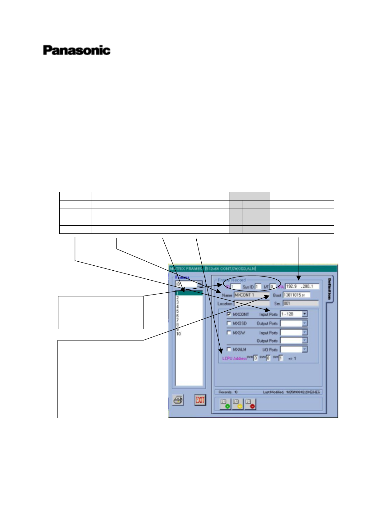
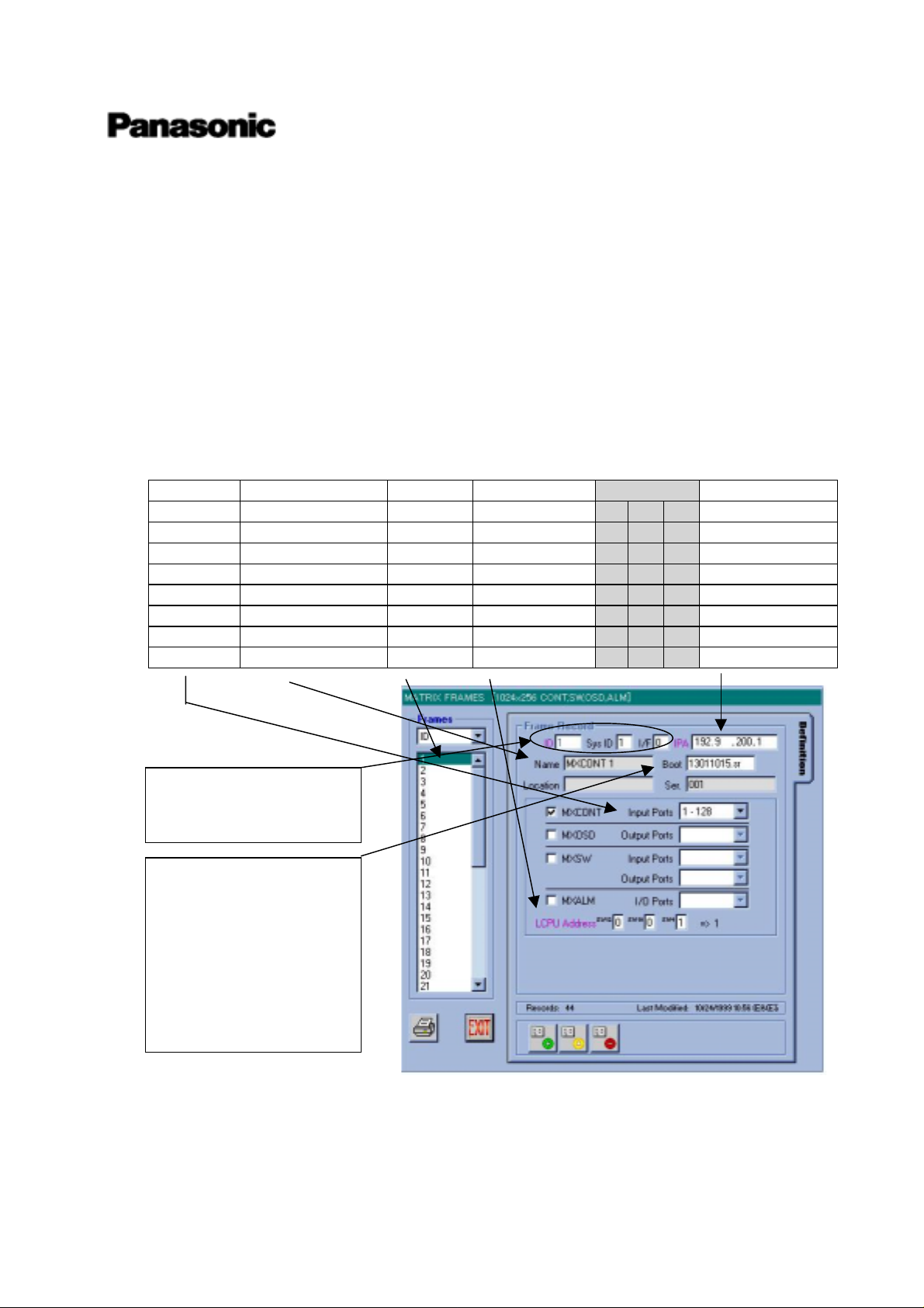
First one is regarding MXCONTs. Key parameters are positioned at the graphical interface of Admin
Console as next. Other parameters shall not be changed.
-1) MXCONTs
Input Symbolic Name Frame ID LCPU Address
LCPU SW IP Address
1~128 MXCONT 1 1 1 0 0 1 192.9.200.1
129~256 MXCONT 2 2 2 0 0 2 192.9.200.2
258~384 MXCONT 3 3 3 0 0 3 192.9.200.3
385~512 MXCONT 4 4 4 0 0 4 192.9.200.4
NOTE:
Please never change these
parameters.
NOTE:
Boot means the software
version of LCPU in
MXFRAME. First released
version is 13011015.sr
Without any announce of
new updated software
version, please never change
it.
Local system engineer will have to adjust the rotary switch (SW9,10,11 on LCPU board) that are
marked with gray hatch in above list.
Version 1.3.0.x
This information is subject to change without notice.
Matsushita Communication Industrial Co., Ltd.
Mar/27/2000
2
Page 4
High Density Video Matrix System
/ 512 x 64 (Standard Model)
1024 x 256 (Expand Model)
8192 x 1024 (Large Model)
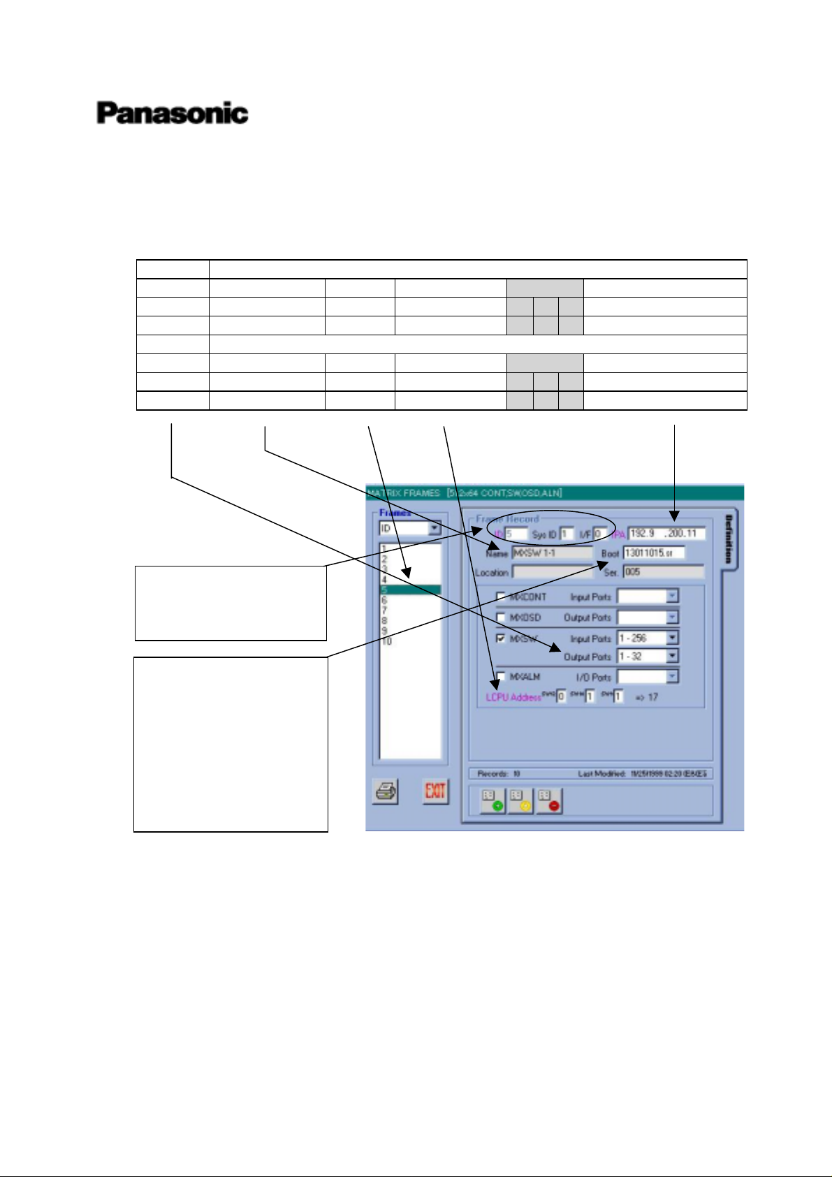
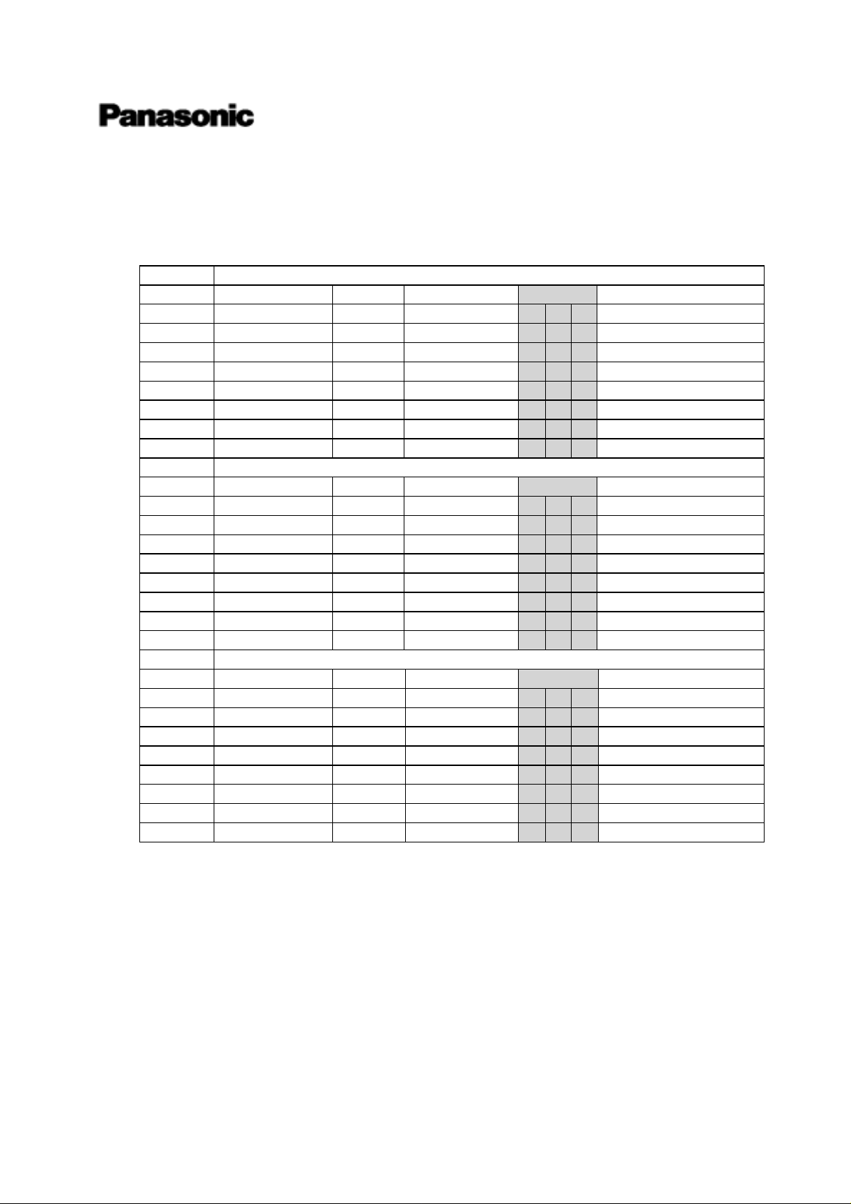
Second one is regarding MXSWs. Key parameters are positioned at the graphical interface of Admin
Console as next. Other parameters shall not be changed.
-2) MXSWs
Input 1~256
Output Symbolic Name Frame ID LCPU Address LCPU SW IP Address
1~32 MXSW 1-1 5 11 0 1 1 192.9.200.11
33~64 MXSW 2-1 7 21 0 2 1 192.9.200.21
Input 257~512
Output Symbolic Name Frame ID LCPU Address LCPU SW IP Address
1~32 MXSW 1-2 6 12 0 1 2 192.9.200.12
33~64 MXSW 2-2 8 22 0 2 2 192.9.200.22
NOTE:
Please never change these
parameters.
NOTE:
Boot means the software
version of LCPU in
MXFRAME. First released
version is 13011015.sr
Without any announce of
new updated software
version, please never change
it.
Local system engineer will have to adjust the rotary switch (SW9,10,11 on LCPU board) that are
marked with gray hatch in above list.
Version 1.3.0.x
This information is subject to change without notice.
Matsushita Communication Industrial Co., Ltd.
Mar/27/2000
3
Page 5
High Density Video Matrix System
/ 512 x 64 (Standard Model)
1024 x 256 (Expand Model)
8192 x 1024 (Large Model)
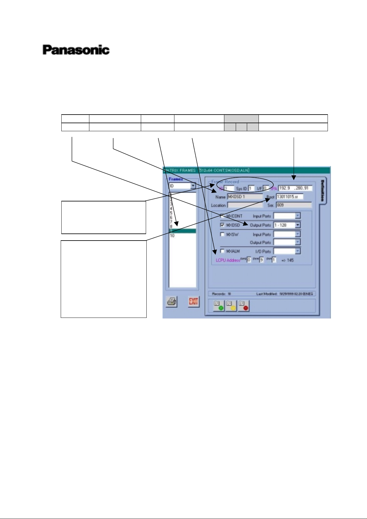
Forth one is regarding MXOSDs. Key parameters are positioned at the graphical interface of Admin
Console as next. Other parameters shall not be changed.
-3) MXOSDs
Output Symbolic Name Frame ID LCPU Address
LCPU SW IP Address
1~128 MXOSD 1 9 91 0 9 1 192.9.200.91
NOTE:
Please never change these
parameters.
NOTE:
Boot means the software
version of LCPU in
MXFRAME. First released
version is 13011015.sr
Without any announce of
new updated software
version, please never change
it.
Local system engineer will have to adjust the rotary switch (SW9,10,11 on LCPU board) that are
marked with gray hatch in above list.
Version 1.3.0.x
This information is subject to change without notice.
Matsushita Communication Industrial Co., Ltd.
Mar/27/2000
4
Page 6
High Density Video Matrix System
/ 512 x 64 (Standard Model)
1024 x 256 (Expand Model)
8192 x 1024 (Large Model)
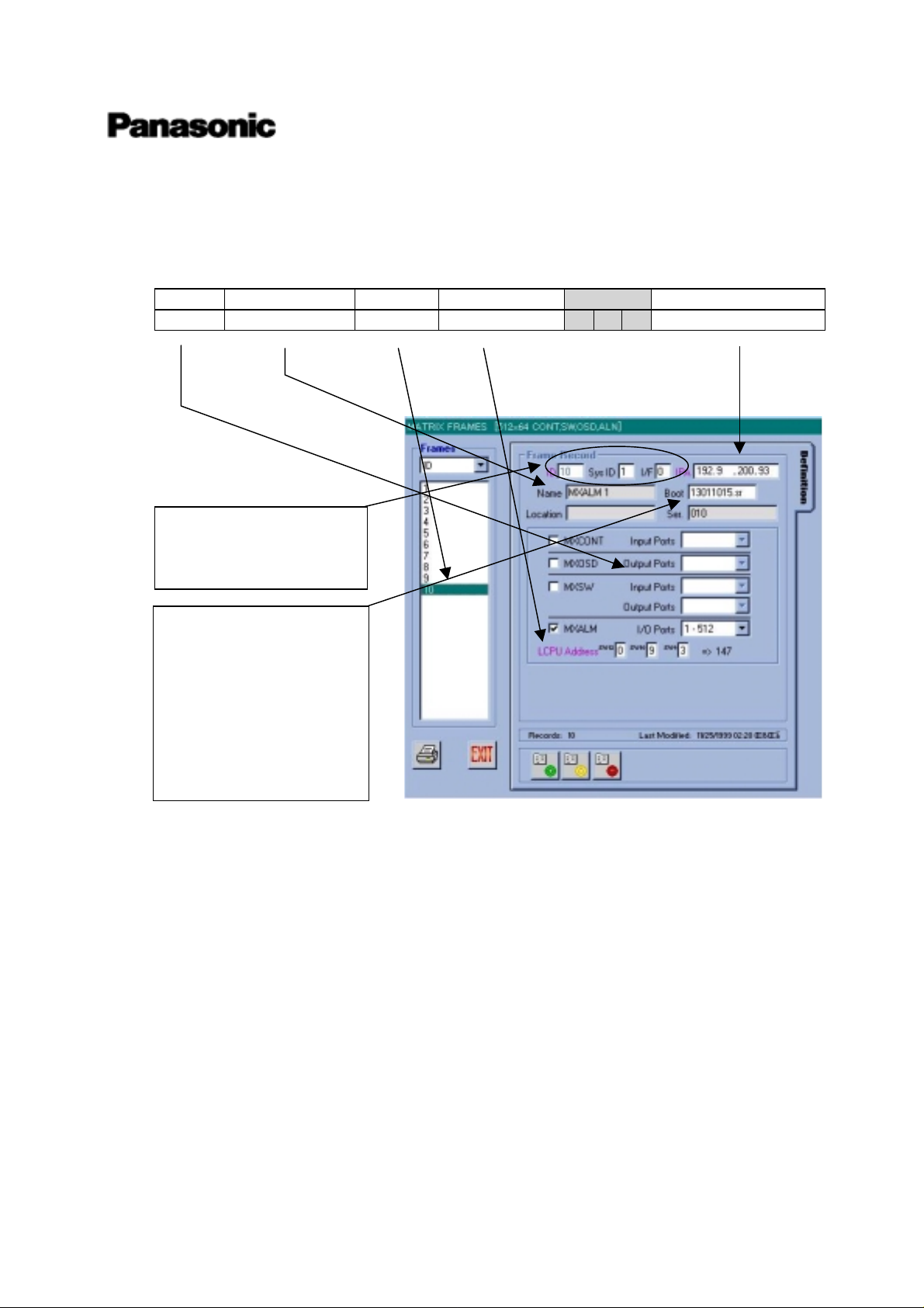
Fifth one is regarding MXALMs. Key parameters are positioned at the graphical interface of Admin
Console as next. Other parameters shall not be changed.
-4) MXALMs
In/Out Symbolic Name Frame ID LCPU Address
LCPU SW IP Address
1~512 MXALM 1 10 93 0 9 3 192. 9. 200. 93
NOTE:
Please never change these
parameters.
NOTE:
Boot means the software
version of LCPU in
MXFRAME. First released
version is 13011015.sr
Without any announce of
new updated software
version, please never change
it.
Local system engineer will have to adjust the rotary switch (SW9,10,11 on LCPU board) that are
marked with gray hatch in above list.
Version 1.3.0.x
This information is subject to change without notice.
Matsushita Communication Industrial Co., Ltd.
Mar/27/2000
5
Page 7
High Density Video Matrix System
/ 512 x 64 (Standard Model)
1024 x 256 (Expand Model)
8192 x 1024 (Large Model)
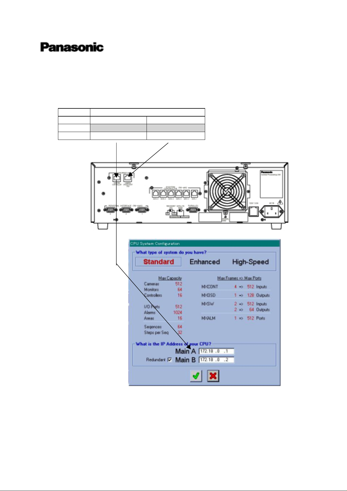
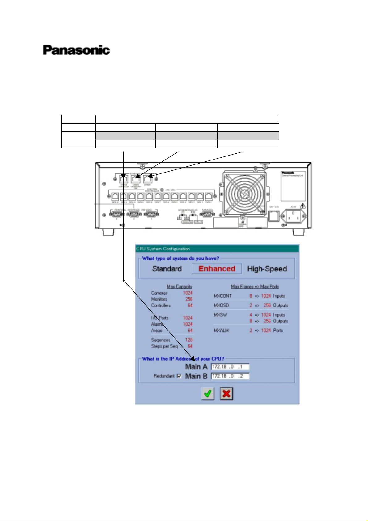
Sixth one is regarding Main CPU. Key parameters are positioned at the graphical interface of Admin
Console as next. Other parameters shall not be changed.
-5) Main CPU
IP Address of Ethernet port
Type Port-1 Port-2
A_CPU 172.18.0.1 192.9.200.200
Default setup
B_CPU 172.18.0.2 192.9.200.201
Standard Main CPU is default setup for A type CPU, then Ethernet port 1 (System Controller) has IP
address = 172.18.0.1 and Ethernet port2 (Camera Cross Point OSD) has IP address = 192.9.200.200.
If you need to change to B type CPU, please refer to “Main CPU A <> B change manual”.
Version 1.3.0.x
This information is subject to change without notice.
Matsushita Communication Industrial Co., Ltd.
Mar/27/2000
6
Page 8
High Density Video Matrix System
/ 512 x 64 (Standard Model)
1024 x 256 (Expand Model)
8192 x 1024 (Large Model)
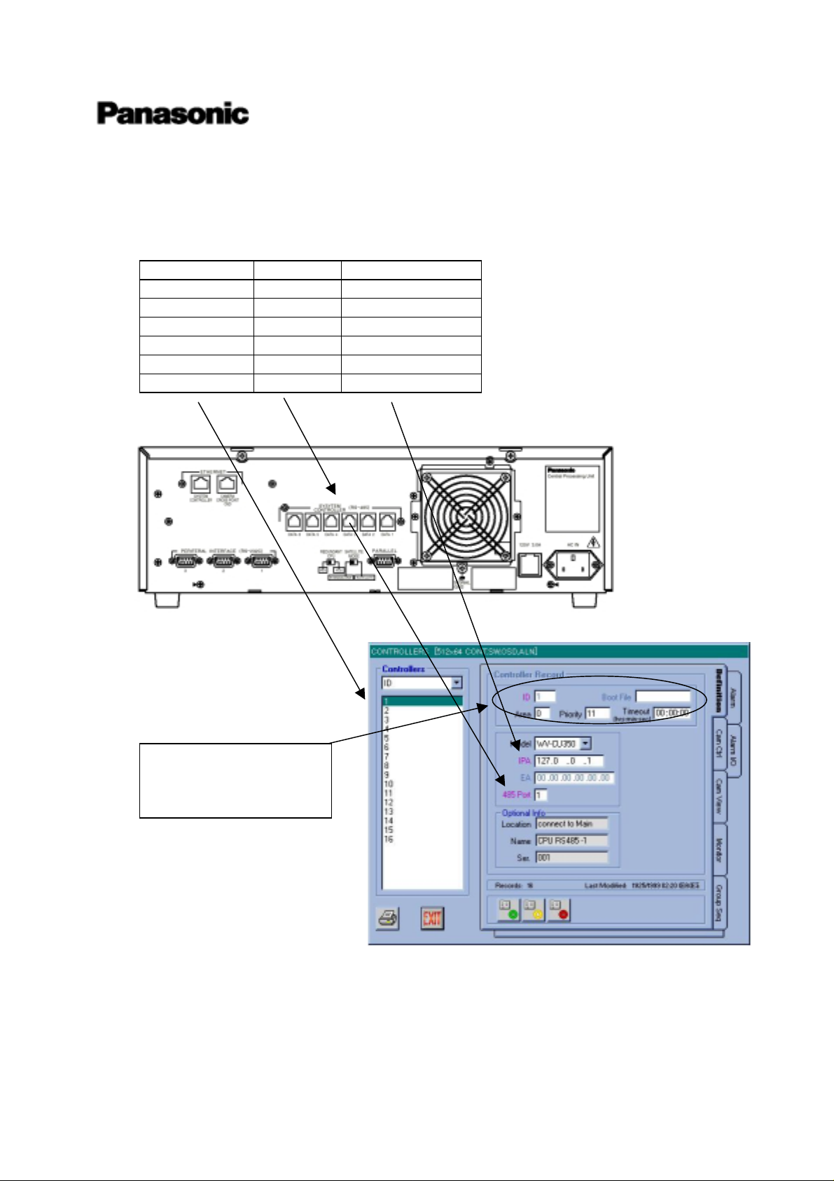
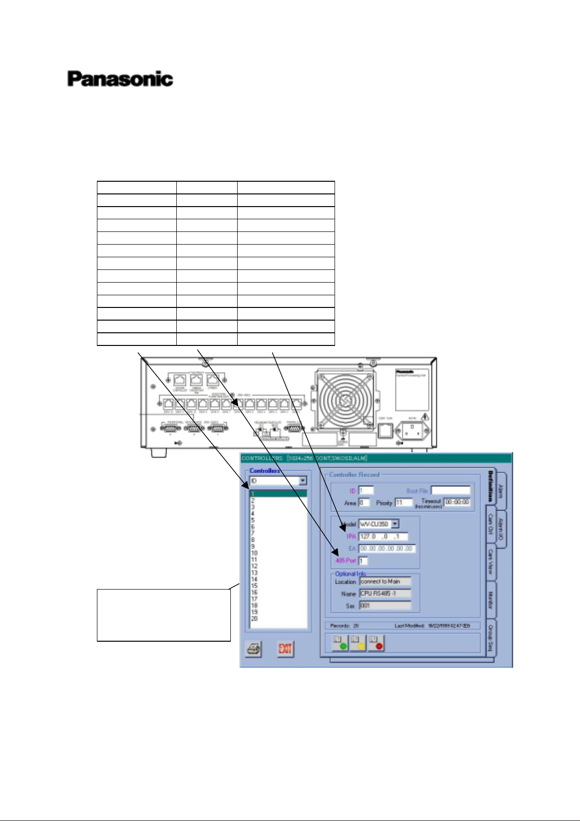
Seventh one is regarding RS485 System Controller (CU350). Key parameters are positioned at the
graphical interface of Admin Console as next. Other parameters shall not be changed.
-6) RS485 System Controller (CU350)
Controller ID 485 port Loop Back IPA
1 1 172.0.0.1
2 2 172.0.0.1
3 3 172.0.0.1
4 4 172.0.0.1
5 5 172.0.0.1
6 6 172.0.0.1
NOTE:
Please never change these
parameters.
RS485 ports number on Main CPU are arranged from right side (rear view) up to left side. But some
products has reveres numbering (from left side up to right side). Please be careful for character
information of port number.
Version 1.3.0.x
This information is subject to change without notice.
Matsushita Communication Industrial Co., Ltd.
Mar/27/2000
7
Page 9
High Density Video Matrix System
/ 512 x 64 (Standard Model)
1024 x 256 (Expand Model)
8192 x 1024 (Large Model)
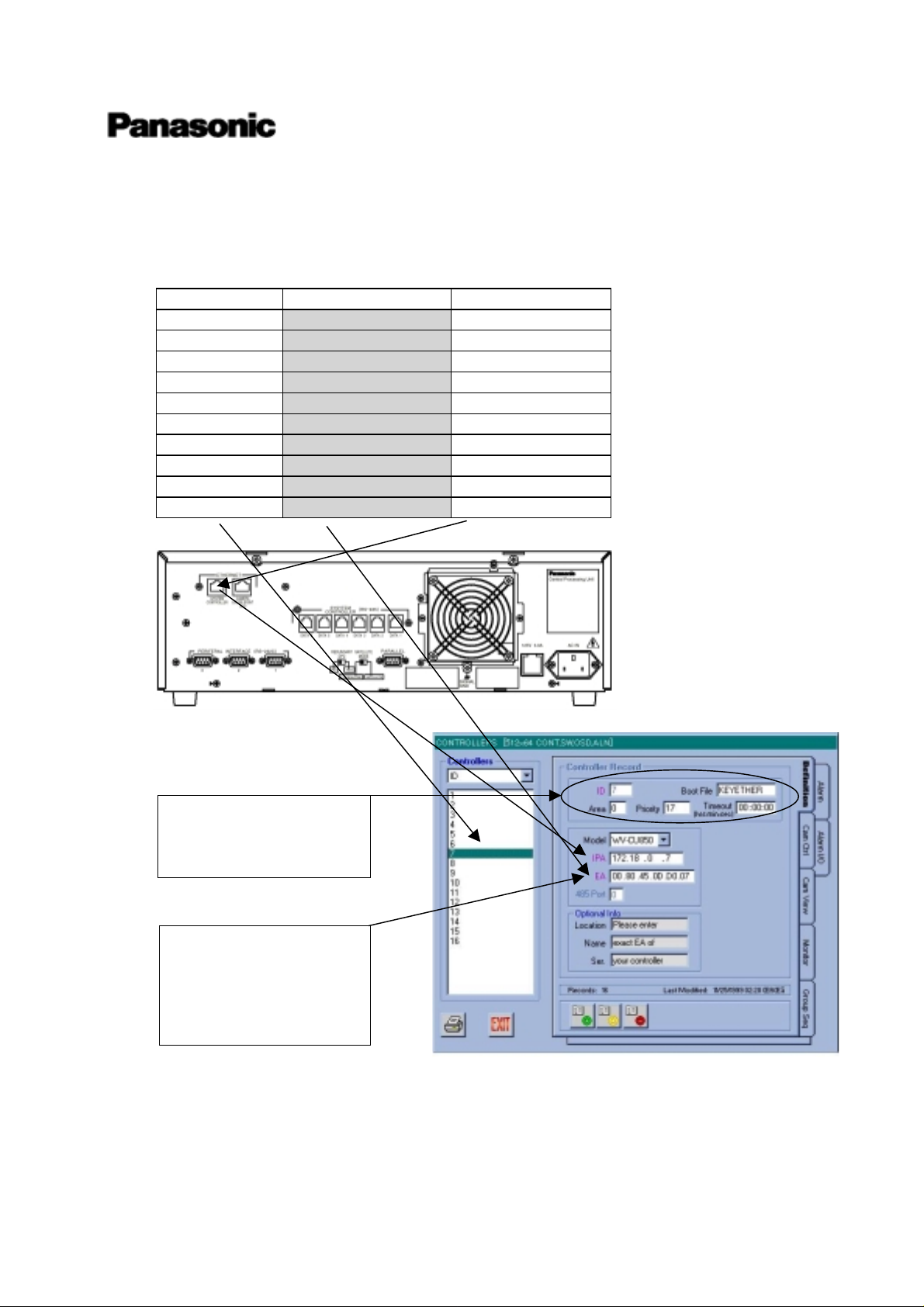
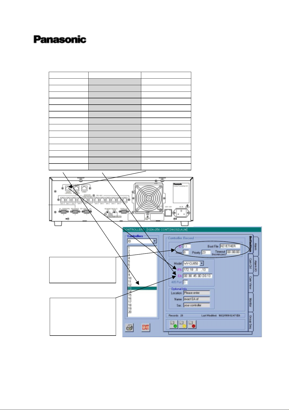
Last one is regarding Ethernet System Controller (CU850). Key parameters are positioned at the
graphical interface of Admin Console as next. Other parameters shall not be changed.
-7) Ethernet System Controller (CU850)
Controller ID Et her net Address Loop Back IPA
7 Input exact E. A. 172.18.0.7
8 Input exact E. A. 172.18.0.8
9 Input exact E. A. 172.18.0.9
10 Input exact E.A. 172.18.0.10
11 Input exact E.A. 172.18.0.11
12 Input exact E.A. 172.18.0.12
13 Input exact E.A. 172.18.0.13
14 Input exact E.A. 172.18.0.14
15 Input exact E.A. 172.18.0.15
16 Input exact E.A. 172.18.0.16
NOTE:
Please never change these
parameters.
NOTE:
Please check E.A. at the
bottom side of CU850.
Each CU850 has E.A. label
at the bottom.
Cataloged database has the sample E.A. (Ethernet Address). Please connect Admin Console and
input exact E.A. of your CU850. Each CU850 has E.A. label at the bottom.
Version 1.3.0.x
This information is subject to change without notice.
Matsushita Communication Industrial Co., Ltd.
Mar/27/2000
8
Page 10

(2) Start Up
Now your are final stage of system install and system setup. Please proceed with next steps:
-1) Power on Main CPU
The power switch of the MPU-850 CPU is located underneath the front panel. Remove the front
panel by removing two screws on the panel.
After powered on, Active indicator will turn on and Hard disk drive indicator will be flashing.
If anything might be wrong, please refer attached documents “Diagnostic of Main CPU”.
-2) Power on miscellaneous devices
Cameras, monitors and Ethernet HUBs shall be powered on.
-3) Power on Matrix Switch Card Cages
The power switch of this cage is located underneath the front panel. Remove the front panel by
removing two screws on the panel.
After powered on, Operate indicator will turn on and LEDs on LCPU will heartbeat and flashing.
High Density Video Matrix System
/ 512 x 64 (Standard Model)
1024 x 256 (Expand Model)
8192 x 1024 (Large Model)
If anything might be wrong or you want to know more details, please refer the attached document
“Diagnostic of MXFRMAE”.
-4) Power on System Controller (CU350)
After connected AC adapter, Operate indicator will turn on, and a litter latter Link indicator will
turn on. Please make sure whether you can login to system
If anything might be wrong, please check the system connection and the database of Admin
Console.
-5) Power on System Controller (CU850)
The power switch of this controller is located at the connector panel.
After powered on, Operate indicator will turn on and a litter latter Link indicator will turn on.
Please make sure whether you can login to system.
If anything might be wrong, please check the system connection and the database of Admin
Console.
(3) Admin Console
Please set IP address “172.18.0.210” for your Administration Console PC, to avoid IP address
conflict.
Version 1.3.0.x
This information is subject to change without notice.
Matsushita Communication Industrial Co., Ltd.
Mar/27/2000
9
Page 11

(4) Help
files.
Console User’s Guide) for operations.
Finally, thanks very much for chousing System 850.
from System 850 development team
High Density Video Matrix System
/ 512 x 64 (Standard Model)
1024 x 256 (Expand Model)
8192 x 1024 (Large Model)
If yon can’t boot up the system successfully, please contact to sales or field engineer with next data
One is Admin Console data file (ex. 512x64 CONT,SW,OSD,ALM.adm).
One is the system initial file (ex. Main A.ini)
These two files are very useful to analyze problems in your system. Please refer “Administration
Version 1.3.0.x
This information is subject to change without notice.
Matsushita Communication Industrial Co., Ltd.
Mar/27/2000
10
Page 12
High Density Video Matrix System
/ 512 x 64 (Standard Model)
1024 x 256 (Expand Model)
8192 x 1024 (Large Model)
4. System Setup of 1,024 x 256
(equal or less than)
(1) Cataloged Database
Enahnced Main CPU has already cataloged system database shown below on his hard disk and you
don’t need to make or change the database at system startup.
There are many parameters in the database, but most important and remarkable parameters are listed
below. Also we will explain about the relation between the graphic interface of Admin Console and this
list.
First one is regarding MXCONTs. Key parameters are positioned at the graphical interface of Admin
Console as next. Other parameters shall not be changed.
-1) MXCONTs
Input Symbolic Name Frame ID LCPU Address
LCPU SW IP Address
1~128 MXCONT 1 1 1 0 0 1 192.9.200.1
129~256 MXCONT 2 2 2 0 0 2 192.9.200.2
258~384 MXCONT 3 3 3 0 0 3 192.9.200.3
385~512 MXCONT 4 4 4 0 0 4 192.9.200.4
513~640 MXCONT 5 5 5 0 0 5 192.9.200.5
641~768 MXCONT 6 6 6 0 0 6 192.9.200.6
769~896 MXCONT 7 7 7 0 0 7 192.9.200.7
897~1024 MXCONT 8 8 8 0 0 8 192.9.200.8
NOTE:
Please never change these
parameters.
NOTE:
Boot means the software
version of LCPU in
MXFRAME. First released
version is 13011015.sr
Without any announce of
new updated software
version, please never change
it.
Local system engineer will have to adjust the rotary switch (SW9,10,11 on LCPU board) that are
marked with gray hatch in above list.
Version 1.3.0.x
This information is subject to change without notice.
Matsushita Communication Industrial Co., Ltd.
Mar/27/2000
11
Page 13
High Density Video Matrix System
/ 512 x 64 (Standard Model)
1024 x 256 (Expand Model)
8192 x 1024 (Large Model)
Second one is regarding MXSWs. Key parameters are positioned at the graphical interface of Admin
Console as next. Other parameters shall not be changed.
-2) MXSWs
Input 1~256
Output Symbolic Name Frame ID LCPU Address LCPU SW IP Address
1~32 MXSW 1-1 9 11 0 1 1 192.9.200.11
33~64 MXSW 2-1 13 21 0 2 1 192.9.200.21
65~96 MXSW 3-1 17 31 0 3 1 192.9.200.31
96~128 MXSW 4-1 21 41 0 4 1 192.9.200.41
129~160 MXSW 5-1 25 51 0 5 1 192.9.200.51
161~192 MXSW 6-1 29 61 0 6 1 192.9.200.61
193~224 MXSW 7-1 33 71 0 7 1 192.9.200.71
225~256 MXSW 8-1 37 81 0 8 1 192.9.200.81
Input 257~512
Output Symbolic Name Frame ID LCPU Address LCPU SW IP Address
1~32 MXSW 1-2 10 12 0 1 2 192.9.200.12
33~64 MXSW 2-2 14 22 0 2 2 192.9.200.22
65~96 MXSW 3-2 18 32 0 3 2 192.9.200.32
96~128 MXSW 4-2 22 42 0 4 2 192.9.200.42
129~160 MXSW 5-2 26 52 0 5 2 192.9.200.52
161~192 MXSW 6-2 30 62 0 6 2 192.9.200.62
193~224 MXSW 7-2 34 72 0 7 2 192.9.200.72
225~256 MXSW 8-2 38 82 0 8 2 192.9.200.82
Input 513~768
Output Symbolic Name Frame I D LCPU Address LCPU SW IP Address
1~32 MXSW 1-3 11 13 0 1 3 192.9.200.13
33~64 MXSW 2-3 15 23 0 2 3 192.9.200.23
65~96 MXSW 3-3 19 33 0 3 3 192.9.200.33
96~128 MXSW 4-3 23 43 0 4 3 192.9.200.43
129~160 MXSW 5-3 27 53 0 5 3 192.9.200.53
161~192 MXSW 6-3 31 63 0 6 3 192.9.200.63
193~224 MXSW 7-3 35 73 0 7 3 192.9.200.73
225~256 MXSW 8-3 39 83 0 8 3 192.9.200.83
Version 1.3.0.x
This information is subject to change without notice.
Matsushita Communication Industrial Co., Ltd.
Mar/27/2000
12
Page 14
High Density Video Matrix System
/ 512 x 64 (Standard Model)
1024 x 256 (Expand Model)
8192 x 1024 (Large Model)
Input 769~1024
Output Symbolic Name Frame ID LCPU Address LCPU SW IP Address
1~32 MXSW 1-4 12 14 0 1 4 192.9.200.14
33~64 MXSW 2-4 16 24 0 2 4 192.9.200.24
65~96 MXSW 3-4 20 34 0 3 4 192.9.200.34
96~128 MXSW 4-4 24 44 0 4 4 192.9.200.44
129~160 MXSW 5-4 28 54 0 5 4 192.9.200.54
161~192 MXSW 6-4 32 64 0 6 4 192.9.200.64
193~224 MXSW 7-4 36 74 0 7 4 192.9.200.74
225~256 MXSW 8-4 40 84 0 8 4 192.9.200.84
NOTE:
Please never change these
parameters.
NOTE:
Boot means the software
version of LCPU in
MXFRAME. First released
version is 13011015.sr
Without any announce of
new updated software
version, please never change
it.
Local system engineer will have to adjust the rotary switch (SW9,10,11 on LCPU board) that are
marked with gray hatch in above list.
Version 1.3.0.x
This information is subject to change without notice.
Matsushita Communication Industrial Co., Ltd.
Mar/27/2000
13
Page 15
High Density Video Matrix System
/ 512 x 64 (Standard Model)
1024 x 256 (Expand Model)
8192 x 1024 (Large Model)
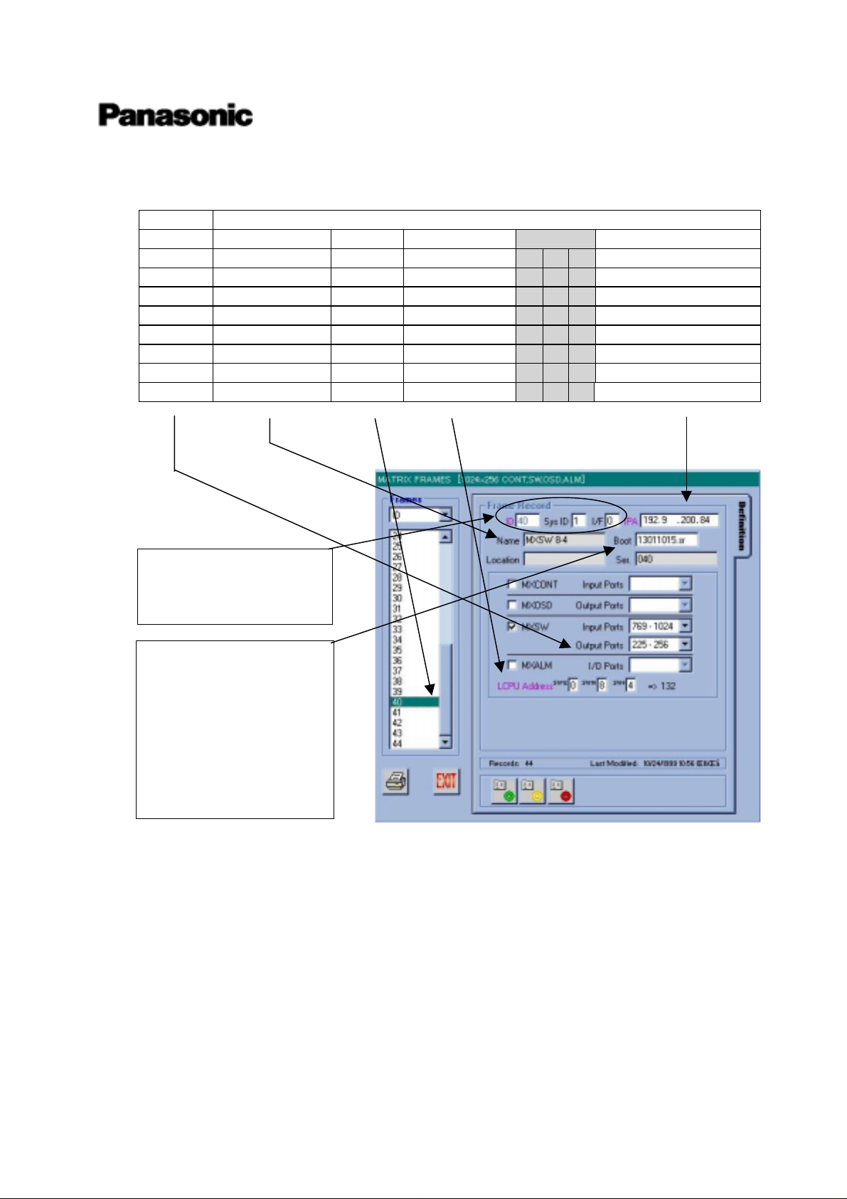
Forth one is regarding MXOSDs. Key parameters are positioned at the graphical interface of Admin
Console as next. Other parameters shall not be changed.
-3) MXOSDs
Output Symbolic Name Frame ID LCPU Address
LCPU SW IP Address
1~128 MXOSD 1 41 91 0 9 1 192.9. 200. 91
129~256 MXOSD 2 42 92 0 9 2 192.9.200.92
NOTE:
Please never change these
parameters.
NOTE:
Boot means the software
version of LCPU in
MXFRAME. First released
version is 13011015.sr
Without any announce of
new updated software
version, please never change
it.
Local system engineer will have to adjust the rotary switch (SW9,10,11 on LCPU board) that are
marked with gray hatch in above list.
Version 1.3.0.x
This information is subject to change without notice.
Matsushita Communication Industrial Co., Ltd.
Mar/27/2000
14
Page 16
High Density Video Matrix System
/ 512 x 64 (Standard Model)
1024 x 256 (Expand Model)
8192 x 1024 (Large Model)
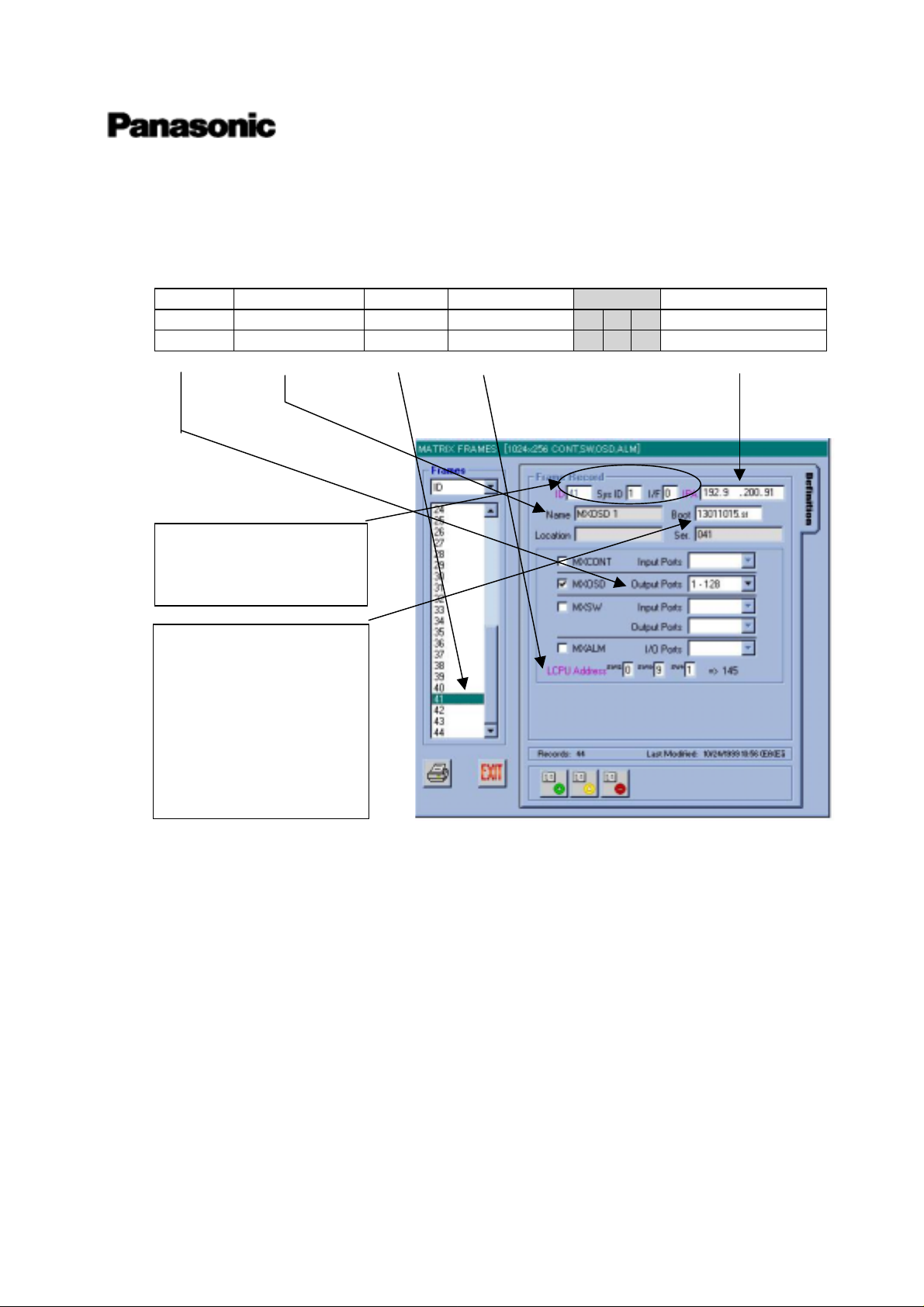
Fifth one is regarding MXALMs. Key parameters are positioned at the graphical interface of Admin
Console as next. Other parameters shall not be changed.
-4) MXALMs
In/Out Symbolic Name Frame ID LCPU Address
LCPU SW IP Address
1~512 MXALM 1 43 93 0 9 3 192.9.200.93
513~1024 MXALM 2 44 94 0 9 4 192.9.200.94
NOTE:
Please never change these
parameters.
NOTE:
Boot means the software
version of LCPU in
MXFRAME. First released
version is 13011015.sr
Without any announce of
new updated software
version, please never change
it.
Local system engineer will have to adjust the rotary switch (SW9,10,11 on LCPU board) that are
marked with gray hatch in above list.
Version 1.3.0.x
This information is subject to change without notice.
Matsushita Communication Industrial Co., Ltd.
Mar/27/2000
15
Page 17
High Density Video Matrix System
/ 512 x 64 (Standard Model)
1024 x 256 (Expand Model)
8192 x 1024 (Large Model)
Sixth one is regarding Main CPU. Key parameters are positioned at the graphical interface of Admin
Console as next. Other parameters shall not be changed.
-5) Main CPU
IP Address of Ethernet port
Type Port-1 Port-2 Port-3
A_CPU 172.18.0.1 192.9.200.200 172.16.192.1
Default setup
B_CPU 172.18.0.2 192.9.200.201 172.16.192.2
Enhanced Main CPU is default setup for A type CPU, then Ethernet port 1 (System Controller) has
IP address = 172.18.0.1, Ethernet port2 (Camera Cross Point OSD) has IP address = 192.9.200.200,
Ethernet port3 (OTHER) has IP address = 172.16.192.1.
If you need to change to B type CPU, please refer to “Main CPU A <> B change manual”.
Version 1.3.0.x
This information is subject to change without notice.
Matsushita Communication Industrial Co., Ltd.
Mar/27/2000
16
Page 18
High Density Video Matrix System
/ 512 x 64 (Standard Model)
1024 x 256 (Expand Model)
8192 x 1024 (Large Model)
Seventh one is regarding RS485 System Controller (CU350). Key parameters are positioned at the
graphical interface of Admin Console as next. Other parameters shall not be changed.
-6) RS485 System Controller (CU350)
Controller ID 485 port Loop Back IPA
1 1 172.0.0.1
2 2 172.0.0.1
3 3 172.0.0.1
4 4 172.0.0.1
5 5 172.0.0.1
6 6 172.0.0.1
7 7 172.0.0.1
8 8 172.0.0.1
9 9 172.0.0.1
10 10 172.0.0.1
11 11 172.0.0.1
12 12 172.0.0.1
NOTE:
Please never change these
parameters.
RS485 ports number on Main CPU are arranged from right side (rear view) up to left side. But some
products has reveres numbering (from left side up to right side). Please be careful for character
information of port number.
Version 1.3.0.x
This information is subject to change without notice.
Matsushita Communication Industrial Co., Ltd.
Mar/27/2000
17
Page 19

High Density Video Matrix System
/ 512 x 64 (Standard Model)
1024 x 256 (Expand Model)
8192 x 1024 (Large Model)
Last one is regarding Ethernet System Controller (CU850). Key parameters are positioned at the
graphical interface of Admin Console as next. Other parameters shall not be changed.
-7) Ethernet System Controller (CU850)
Controller ID Et her net Address Loop Back IPA
13 Input exact E.A. 172.18.0.13
14 Input exact E.A. 172.18.0.14
15 Input exact E.A. 172.18.0.15
16 Input exact E.A. 172.18.0.16
17 Input exact E.A. 172.18.0.17
18 Input exact E.A. 172.18.0.18
19 Input exact E.A. 172.18.0.19
20 Input exact E.A. 172.18.0.20
21 Input exact E.A. 172.18.0.21
22 Input exact E.A. 172.18.0.22
23 Input exact E.A. 172.18.0.23
24 Input exact E.A. 172.18.0.24
25 Input exact E.A. 172.18.0.25
26 Input exact E.A. 172.18.0.26
27 Input exact E.A. 172.18.0.27
28 Input exact E.A. 172.18.0.28
29 Input exact E.A. 172.18.0.29
30 Input exact E.A. 172.18.0.30
31 Input exact E.A. 172.18.0.31
32 Input exact E.A. 172.18.0.32
33 Input exact E.A. 172.18.0.33
34 Input exact E.A. 172.18.0.34
35 Input exact E.A. 172.18.0.35
36 Input exact E.A. 172.18.0.36
37 Input exact E.A. 172.18.0.37
38 Input exact E.A. 172.18.0.38
39 Input exact E.A. 172.18.0.39
40 Input exact E.A. 172.18.0.40
41 Input exact E.A. 172.18.0.41
42 Input exact E.A. 172.18.0.42
43 Input exact E.A. 172.18.0.43
44 Input exact E.A. 172.18.0.44
45 Input exact E.A. 172.18.0.45
46 Input exact E.A. 172.18.0.46
47 Input exact E.A. 172.18.0.47
48 Input exact E.A. 172.18.0.48
49 Input exact E.A. 172.18.0.49
50 Input exact E.A. 172.18.0.50
Version 1.3.0.x
This information is subject to change without notice.
Matsushita Communication Industrial Co., Ltd.
Mar/27/2000
18
Page 20
Controller ID Et her net Address Loop Back IPA
51 Input exact E.A. 172.18.0.51
52 Input exact E.A. 172.18.0.52
53 Input exact E.A. 172.18.0.53
54 Input exact E.A. 172.18.0.54
55 Input exact E.A. 172.18.0.55
56 Input exact E.A. 172.18.0.56
57 Input exact E.A. 172.18.0.57
58 Input exact E.A. 172.18.0.58
59 Input exact E.A. 172.18.0.59
60 Input exact E.A. 172.18.0.60
61 Input exact E.A. 172.18.0.61
62 Input exact E.A. 172.18.0.62
63 Input exact E.A. 172.18.0.63
64 Input exact E.A. 172.18.0.64
High Density Video Matrix System
/ 512 x 64 (Standard Model)
1024 x 256 (Expand Model)
8192 x 1024 (Large Model)
NOTE:
Please never change these
parameters.
NOTE:
Please check E.A. at the
bottom side of CU850.
Each CU850 has E.A. label
at the bottom.
Cataloged database has the sample E.A. (Ethernet Address). Please connect Admin Console and input
exact E.A. of your CU850. Each CU850 has E.A. label at the bottom.
Version 1.3.0.x
This information is subject to change without notice.
Matsushita Communication Industrial Co., Ltd.
Mar/27/2000
19
Page 21

(2) Start Up
Now your are final stage of system install and system setup. Please proceed with next setps:
-1) Power on Main CPU
The power switch of the MPU-855 CPU is located underneath the front panel. Remove the front
panel by removing two screws on the panel.
After powered on, Active indicator will turn on and Hard disk drive indicator will be flashing.
If anything might be wrong, please refer attached documents “Diagnostic of Main CPU”.
-2) Power on miscellaneous devices
Cameras, monitors and Ethernet HUBs shall be powered on.
-3) Power on Matrix Switch Card Cages
The power switch of this cage is located underneath the front panel. Remove the front panel by
removing two screws on the panel.
After powered on, Operate indicator will turn on and LEDs on LCPU will heartbeat and flashing.
High Density Video Matrix System
/ 512 x 64 (Standard Model)
1024 x 256 (Expand Model)
8192 x 1024 (Large Model)
If anything might be wrong or you want to know more details, please refer the attached document
“Diagnostic of MXFRMAE”.
-4) Power on System Controller (CU350)
After connected AC adapter, Operate indicator will turn on, and a litter latter Link indicator will
turn on. Please make sure whether you can login to system
If anything might be wrong, please check the system connection and the database of Admin
Console.
-5) Power on System Controller (CU850)
The power switch of this controller is located at the connector panel.
After powered on, Operate indicator will turn on and a litter latter Link indicator will turn on.
Please make sure whether you can login to system.
If anything might be wrong, please check the system connection and the database of Admin
Console.
(3) Admin Console
Please set IP address “172.18.0.210” for your Administration Console PC, to avoid IP address
conflict.
Version 1.3.0.x
This information is subject to change without notice.
Matsushita Communication Industrial Co., Ltd.
Mar/27/2000
20
Page 22

Over
High Density Video Matrix System
/ 512 x 64 (Standard Model)
1024 x 256 (Expand Model)
8192 x 1024 (Large Model)
(4) Help
If yon can’t boot up the system successfully, please contact to sales or field engineer with next data
files.
One is Admin Console data file (ex. 1024x256 CONT,SW,OSD,ALM.adm).
One is the system initial file (ex. Main A.ini)
These two files are very useful to analyze problems in your system. Please refer “Administration
Console User’s Guide) for operations.
Finally, thanks very much for chousing System 850.
from System 850 development team
Mar. 27th 2000
Matsushita Communication Industrial Co., Ltd. V8QA5520A4
Version 1.3.0.x
This information is subject to change without notice.
Matsushita Communication Industrial Co., Ltd.
Mar/27/2000
21
Page 23

Hig h D en si t y V i deo M at r i x S yst em 850
sys.ini Configuration
For Version1.3.0.x
<INDEX>
High Density Video Matrix System 850
/ 512 x 64 (Standard M odel)
1024 x 256 (Expand Model)
8192 x 1024 (Large Model)
1. Introduction
2. System Section
3. Interface Section
4. Frames Section
5. Procs Section
6. OSD Section
7. Errorp Section
8. 512by64 sample
9. 1024by256 sample
10. 160by16 Mix Config sample
Mar/27/2000
Matsushita Communication Industrial Co., Ltd.
Page 24

High Density Video Matrix System 850
/ 512 x 64 (Standard M odel)
1024 x 256 (Expand M odel)
8192 x 1024 (Large Model)
1. Introduction
“sys.ini” file is a special file and normally not changed. This file defines the system scale, Ethernet
interface assignment, matrix frame configuration, process interface assignment and OSD format. And these
configuration or assignment must be matched to the admin configuration. Unless the matching, the main
CPU does not work properly.
2. System section
[SYSTEM]
Keyboards=64
Cameras=768
Monitors=64
These numbers are defined by actual count and must be less or equal than the number depends on CPU
type.If the camera number is registered 768 in admin and described 256 in sys.ini, operator can select just 256
cameras.
3. Interface section
[INTERFACES]
*** Number of interfaces in the system
Numinterfaces=3 fl This is the number of Ethernet ports on Main CPU.
The number of Ethernet ports depends on Main CPU type.
Standard CPU: 2 port, Enhanced CPU: 3 ports
*** Interface Definition
*** Interface<Number>=<IPA>,<SUBNET MASK>,<BOOT SERVER IPA>
Interface0=192.9.200.200,255.255.255.0,192.9.200.200
fl Interface0 is a n interface for mainly MXFRM, sometimes for both MXFRM and
system controller. This value is for Main CPU A. For main CPU B, this value
is changed as follow. 192.9.200.201,255.255.255.0,192.9.200.201
Interface1=172.18.0.1,255.255.0.0,172.18.0.1
fl Interface1 is a n interface for system controller or PFW850. This value is for
Main CPU A. For main CPU B, this value is changed as follow.
172.18.0.2,255.255.0.0,172.18.0.2
Interface2=172.16.192.1,255.255.0.0,172.16.192.1
fl Interface2 is not used in current version. This will be used for a satellite system
in the future.. This value is for Main CPU A. For main CPU B, this value is
changed as follow. 172.16.192.2,255.255.0.0,172.16.192.2
Unless above IP address are not matched to actual MainCPU’s IP address, Main CPU
never starts to work.
4. Frames section
[FRAMES]
NumFrames=14 fl This number must be matched to MX frame number in admin. Unless the match-
ing, Main CPU does not start to work.
*** MXSW has form <num_rows>,<num_cols>,<interface_num>
*** All others use <num_functions>,<interface_num>
sys.ini configuration
This information is subject to change without notice.
1
Page 25

High Density Video Matrix System 850
/ 512 x 64 (Standard M odel)
1024 x 256 (Expand M odel)
8192 x 1024 (Large Model)
MXSWFunction=2,3,0 fl <num_rows> and <num_cols> are defined by Table 1. <interface_num> must
be always “0” in current implementation of Main CPU software.
MXCONTFunction=6,0 fl <num_function> is defined from number of MXCONT card cage. < inter-
face_num> must be always “0” in current implementation of Main CPU software.
MXOSDFunction=1,0 fl <num_function> is defined from number of MXOSD card cage. <
interface_num> must be always “0” in current implementation of Main CPU
software.MXDIOFunction=1,0 fl <num_function> is defined from number of MXALM card cage. <
interface_num> must be always “0” in current implementation of Main CPU
software.MXRMSFunction=0,0 fl <num_function> is defined from number of MXSW card cage for VCR manage ment system. AVSD does not support this portion because AVSD does not produce the VCR management system now. < interface_num> must be always
“0” in current implementation of Main CPU software.
Table 1 MXSW Matrix Address Assignments
Each MXSW function is capable of managing 256 inputs and 32 outputs. Because the MXSW functions form a
video-switching matrix, the MXSW address is composed of two elements: (1) a row address, and (2) a column
address. The relationship between the MXSW matrix address and global port numbers is shown in Table 1.
MXSW Matrix Address Global Input Port Number Global Output Port Number
Row Column Minimum Maximum Minimum Maximum
1 1 1 256 1 32
1 2 257 512 1 32
1 3 513 768 1 32
1 4 769 1024 1 32
2 1 1 256 33 64
2 2 257 512 33 64
2 3 513 768 33 64
2 4 769 1024 33 64
••••••
••••••
••••••
7 1 1 256 193 224
7 2 257 512 193 224
7 3 513 768 193 224
7 4 769 1024 193 224
8 1 1 256 225 256
8 2 257 512 225 256
8 3 513 768 225 256
8 4 769 1024 225 256
This information is subject to change without notice.
sys.ini configuration
2
Page 26

High Density Video Matrix System 850
/ 512 x 64 (Standard M odel)
1024 x 256 (Expand M odel)
8192 x 1024 (Large Model)
5. Procs section
[PROCS]
*** Process Interface Assignments
*** Format: <Process Name>=<interface_num>
*** Set the following to the interface_num of the Ethernet keyboards:
Keybp=0 flinterface_num=0: 192.9.200.200 as CPUA or 192.9.200.201 as CPUB.
Mxconts=0 Current Main CPU software allows same numbers in these three process.
Mxpfw=0
*** Set the following to the interface_num of the RS485 Expansion Unit:
Kexs=0
*** Set the following to the interface_num of the MainCPU:
Swcpu=0 fl For redundant system, Both CPUA and CPUB must be assigned same interface_num.
6. OSD section
[OSD]
*** Initial OSD display position.
*** Format: <DisplayItemPosition> = <x-position>,<y-position>
‡The x-position can range from 1to 40. The y-position can range from 1 to 16
TimeDatePosition=1,1
CamTitlePosition=1,16
MonStatusPosition=1,15
GenStatusPosition=1,14
*** Time and Date display Format: TimeDateFormat=<format>
*** format 0 – DD/MM/YYYY
*** format 1 – MM/DD/YYYY
*** format 2 – DD/Mmm/YYYY
*** format 3 – YYYY/MM/DD
TimeDateFormat=1
When change the position, it needs to reboot MXOSD cage.
7. Errorp section
[ERRORP]
*** Error messages with error level equal to or higher than <errorlevel> will be saved
*** to error.log. Format:ErrorLevel=<errorlevel>.
*** <errorlevel> can range from 0, least critical, to 4, most critical.
ErrorLevel=3
sys.ini configuration
This information is subject to change without notice.
3
Page 27

8. 512by64 Standard CPU system sample
[SYSTEM]
Keyboards=16
Cameras=512
Monitors=64
[INTERFACES]
*** Number of interfaces in the system
NumInterfaces=2
*** Interface Definition
*** Interface<Number>=<IPA>,<SUBNET MASK>,<BOOT SERVER IPA>
Interface0=192.9.200.200,255.255.255.0,192.9.200.200
Interface1=172.18.0.1,255.255.0.0,172.18.0.1
*** Interface2=172.16.192.1,255.255.0.0,172.16.192.1
Note)----In case of Main CPU B, IPA must be set as below---Interface0=192.9.200.201,255.255.255.0,192.9.200.201
Interface1=172.18.0.2,255.255.0.0,172.18.0.2
*** Interface2=172.16.192.2,255.255.0.0,172.16.192.2
---------------------------------------------------------------------------
High Density Video Matrix System 850
/ 512 x 64 (Standard M odel)
1024 x 256 (Expand M odel)
8192 x 1024 (Large Model)
[FRAMES]
NumFrames=10
*** MXSW has form <num_rows>,<num_cols>,<interface_num>
*** All others use <num_functions>,<interface_num>
MXSWFunction=2,2,0
MXCONTFunction=4,0
MXOSDFunction=1,0
MXDIOFunction=1,0
MXRMSFunction=0,0
[PROCS]
*** Process Interface Assignments
*** Format: <Process Name>=<interface_num>
*** Set the following to the interface_num of the Ethernet keyboards:
Keybp=1
Mxconts=1
Mxpfw=1
*** Set the following to the interface_num of the RS485 Expansion Unit:
Kexs=1
*** Set the following to the interface_num of the MainCPU:
Swcpu=0
[OSD]
*** Initial OSD display position.
*** Format: <DisplayItemPosition> = <x-position>,<y-position>
TimeDatePosition=1,1
CamTitlePosition=1,16
This information is subject to change without notice.
sys.ini configuration
4
Page 28

High Density Video Matrix System 850
/ 512 x 64 (Standard M odel)
1024 x 256 (Expand M odel)
8192 x 1024 (Large Model)
MonStatusPosition=1,15
GenStatusPosition=1,14
*** Time and Date display Format: TimeDateFormat=<format>
*** format 0 - DD/MM/YYYY
*** format 1 - MM/DD/YYYY
*** format 2 - DD/Mmm/YYYY
*** format 3 - YYYY/MM/DD
TimeDateFormat=1
[ERRORP]
*** Error messages with error level equal to or higher than <errorlevel> will be saved
*** to error.log. Format: ErrorLevel=<errorlevel>.
*** <errorlevel> can range from 0, least critical, to 4, most critical.
ErrorLevel=3
Matrix Card cage configuration in Admin based on above sys.ini.
Frame
ID
1 0 0 1 192.9.200.1 MXCONT1: 1-128
2 0 0 2 192.9.200.2 MXCONT2: 129-256
3 0 0 3 192.9.200.3 MXCONT3: 257-384
4 0 0 4 192.9.200.4 MXCONT4: 385-512
5 0 1 1 192.9.200.11 MXSW1-1: 1-256, 1-32
6 0 1 2 192.9.200.12 MXSW1-2: 257-512, 1-32
7 0 2 1 192.9.200.21 MXSW2-1: 1-256, 33-64
8 0 2 2 192.9.200.22 MXSW2-2: 257-512, 33-64
9 0 9 1 192.9.200.91 MXOSD1: 1-128
10 0 9 3 192.9.200.93 MXALM1: 1-512
LCPU Address IP Address Matrix Function
9. 1024by256 Enhanced CPU system sample
[SYSTEM]
Keyboards=64
Cameras=1024
Monitors=256
[INTERFACES]
*** Number of interfaces in the system
NumInterfaces=3
*** Interface Definition
*** Interface<Number>=<IPA>,<SUBNET MASK>,<BOOT SERVER IPA>
Interface0=192.9.200.200,255.255.255.0,192.9.200.200
Interface1=172.18.0.1,255.255.0.0,172.18.0.1
Interface2=172.16.192.1,255.255.0.0,172.16.192.1
Note)----In case of Main CPU B, IPA must be set as below---Interface0=192.9.200.201,255.255.255.0,192.9.200.201
Interface1=172.18.0.2,255.255.0.0,172.18.0.2
Interface2=172.16.192.2,255.255.0.0,172.16.192.2
--------------------------------------------------------------------------[FRAMES]
NumFrames=44
*** MXSW has form <num_rows>,<num_cols>,<interface_num>
This information is subject to change without notice.
sys.ini configuration
5
Page 29

High Density Video Matrix System 850
*** All others use <num_functions>,<interface_num>
MXSWFunction=8,4,0
MXCONTFunction=8,0
MXOSDFunction=2,0
MXDIOFunction=2,0
MXRMSFunction=0,0
[PROCS]
*** Process Interface Assignments
*** Format: <Process Name>=<interface_num>
*** Set the following to the interface_num of the Ethernet keyboards:
Keybp=1
Mxconts=1
Mxpfw=1
*** Set the following to the interface_num of the RS485 Expansion Unit:
Kexs=1
*** Set the following to the interface_num of the MainCPU:
Swcpu=0
[OSD]
*** Initial OSD display position.
*** Format: <DisplayItemPosition> = <x-position>,<y-position>
TimeDatePosition=1,1
CamTitlePosition=1,16
MonStatusPosition=1,15
GenStatusPosition=1,14
*** Time and Date display Format: TimeDateFormat=<format>
*** format 0 - DD/MM/YYYY
*** format 1 - MM/DD/YYYY
*** format 2 - DD/Mmm/YYYY
*** format 3 - YYYY/MM/DD
TimeDateFormat=1
/ 512 x 64 (Standard M odel)
1024 x 256 (Expand M odel)
8192 x 1024 (Large Model)
[ERRORP]
*** Error messages with error level equal to or higher than <errorlevel> will be saved
*** to error.log. Format: ErrorLevel=<errorlevel>.
*** <errorlevel> can range from 0, least critical, to 4, most critical.
ErrorLevel=3
Matrix Card cage configuration in Admin based on above sys.ini.
Frame
ID
1 0 0 1 192.9.200.1 MXCONT1: 1-128
LCPU Address IP Address Matrix Function
2 0 0 2 192.9.200.2 MXCONT2: 129-256
3 0 0 3 192.9.200.3 MXCONT3: 257-384
4 0 0 4 192.9.200.4 MXCONT4: 385-512
This information is subject to change without notice.
sys.ini configuration
6
Page 30

High Density Video Matrix System 850
/ 512 x 64 (Standard M odel)
1024 x 256 (Expand M odel)
8192 x 1024 (Large Model)
5 0 0 5 192.9.200.5 MXCONT5: 513-640
6 0 0 6 192.9.200.6 MXCONT6: 641-768
7 0 0 7 192.9.200.7 MXCONT7: 769-896
8 0 0 8 192.9.200.8 MXCONT8: 897-1024
9 0 1 1 192.9.200.11 MXSW1-1: 1-256, 1-32
10 0 1 2 192.9.200.12 MXSW1-2: 257-512, 1-32
11 0 1 3 192.9.200.13 MXSW1-3: 513-768, 1-32
12 0 1 4 192.9.200.14 MXSW1-4: 769-1024, 1-32
13 0 2 1 192.9.200.21 MXSW2-1: 1-256, 33-64
14 0 2 2 192.9.200.22 MXSW2-2: 257-512, 33-64
15 0 2 3 192.9.200.23 MXSW2-3: 513-768, 33-64
16 0 2 4 192.9.200.24 MXSW2-4: 769-1024, 33-64
17 0 3 1 192.9.200.31 MXSW3-1: 1-256, 65-96
18 0 3 2 192.9.200.32 MXSW3-2: 257-512, 65-96
19 0 3 3 192.9.200.33 MXSW3-3: 513-768, 65-96
20 0 3 4 192.9.200.34 MXSW3-4: 769-1024, 65-96
21 0 4 1 192.9.200.41 MXSW4-1: 1-256, 97-128
22 0 4 2 192.9.200.42 MXSW4-2: 257-512, 97-128
23 0 4 3 192.9.200.43 MXSW4-3: 513-768, 97-128
24 0 4 4 192.9.200.44 MXSW4-4: 769-1024, 97-128
25 0 5 1 192.9.200.51 MXSW5-1: 1-256, 128-160
26 0 5 2 192.9.200.52 MXSW5-2: 257-512, 128-160
27 0 5 3 192.9.200.53 MXSW5-3: 513-768, 128-160
28 0 5 4 192.9.200.54 MXSW5-4: 769-1024, 128-160
29 0 6 1 192.9.200.61 MXSW6-1: 1-256, 161-192
30 0 6 2 192.9.200.62 MXSW6-2: 257-512, 161-192
31 0 6 3 192.9.200.63 MXSW6-3: 513-768, 161-192
32 0 6 4 192.9.200.64 MXSW6-4: 769-1024, 161-192
33 0 7 1 192.9.200.71 MXSW7-1: 1-256, 193-224
34 0 7 2 192.9.200.72 MXSW7-2: 257-512, 193-224
35 0 7 3 192.9.200.73 MXSW7-3: 513-768, 193-224
36 0 7 4 192.9.200.74 MXSW7-4: 769-1024, 193-224
37 0 8 1 192.9.200.81 MXSW8-1: 1-256, 225-256
38 0 8 2 192.9.200.82 MXSW8-2: 257-512, 225-256
39 0 8 3 192.9.200.83 MXSW8-3: 513-768, 225-256
40 0 8 4 192.9.200.84 MXSW8-4: 769-1024, 225-256
41 0 9 1 192.9.200.91 MXOSD1: 1-128
42 0 9 2 192.9.200.92 MXOSD2: 129-256
43 0 9 3 192.9.200.93 MXALM1: 1-512
44 0 9 4 192.9.200.94 MXALM2: 513-1024
This information is subject to change without notice.
sys.ini configuration
7
Page 31

High Density Video Matrix System 850
/ 512 x 64 (Standard M odel)
1024 x 256 (Expand M odel)
8192 x 1024 (Large Model)
10. 160by16 Enhanced CPU system Mix Configuration sample
[SYSTEM]
Keyboards=16
Cameras=512
Monitors=64
[INTERFACES]
*** Number of interfaces in the system
NumInterfaces=2
*** Interface Definition
*** Interface<Number>=<IPA>,<SUBNET MASK>,<BOOT SERVER IPA>
Interface0=192.9.200.200,255.255.255.0,192.9.200.200
Interface1=172.18.0.1,255.255.0.0,172.18.0.1
*** Interface2=172.16.192.1,255.255.0.0,172.16.192.1
Note)----In case of Main CPU B, IPA must be set as below---Interface0=192.9.200.201,255.255.255.0,192.9.200.201
Interface1=172.18.0.2,255.255.0.0,172.18.0.2
*** Interface2=172.16.192.2,255.255.0.0,172.16.192.2
--------------------------------------------------------------------------[FRAMES]
NumFrames=2
*** MXSW has form <num_rows>,<num_cols>,<interface_num>
*** All others use <num_functions>,<interface_num>
MXSWFunction=1,1,0
MXCONTFunction=2,0
MXOSDFunction=1,0
MXDIOFunction=0,0
MXRMSFunction=0,0
[PROCS]
*** Process Interface Assignments
*** Format: <Process Name>=<interface_num>
*** Set the following to the interface_num of the Ethernet keyboards:
Keybp=1
Mxconts=1
Mxpfw=1
*** Set the following to the interface_num of the RS485 Expansion Unit:
Kexs=1
*** Set the following to the interface_num of the MainCPU:
Swcpu=0
[OSD]
*** Initial OSD display position.
*** Format: <DisplayItemPosition> = <x-position>,<y-position>
TimeDatePosition=1,1
This information is subject to change without notice.
sys.ini configuration
8
Page 32

High Density Video Matrix System 850
/ 512 x 64 (Standard M odel)
1024 x 256 (Expand M odel)
8192 x 1024 (Large Model)
CamTitlePosition=1,16
MonStatusPosition=1,15
GenStatusPosition=1,14
*** Time and Date display Format: TimeDateFormat=<format>
*** format 0 - DD/MM/YYYY
*** format 1 - MM/DD/YYYY
*** format 2 - DD/Mmm/YYYY
*** format 3 - YYYY/MM/DD
TimeDateFormat=1
[ERRORP]
*** Error messages with error level equal to or higher than <errorlevel> will be saved
*** to error.log. Format: ErrorLevel=<errorlevel>.
*** <errorlevel> can range from 0, least critical, to 4, most critical.
ErrorLevel=3
Matrix Card cage configuration in Admin based on above sys.ini.
Frame
ID
1 0 0 1 192.9.200.1 MXCONT1: 1-128
LCPU Address IP Address Matrix Function
2 0 0 2 192.9.200.2 MXCONT2: 129-256
MXSW1-1: 1-256
MXOSD1: 1-128
For mix configuration, the “NumFrames=2” in sys.ini and admin configuration of MX sec-
tion must match to actual card cage number.
Over
Mar. 27th 2000
Matsushita Communication Industrial Co., Ltd.
V8QA5523A4
This information is subject to change without notice.
sys.ini configuration
9
Page 33

Hig h D en si t y V i deo M at r i x S yst em 850
Diagnostic of Main CPU
For Version1.3.0.x
INDEX
High Density Video Matrix System 850
/ 512 x 64 (Standard M odel)
1024 x 256 (Enhanced Model)
8192 x 1024 (High speed Model)
Introduction
Preparation
Diagnostic -1
Diagnostic -2
Diagnostic -3
Diagnostic -4
Mar/27/2000
Matsushita Communication Industrial Co., Ltd.
1. Introduction
In case a MCPU Unit (Standard or Enhanced) seems to be faulty, check it according to the following
procedure.
Page 34

2. Preparation
Prepare a PC having the following features:
(1) Minimum Hardware Requirements
IBM compatible PC, 486-66Mz or higher, 16 MB RAM, hard disk drive with 20 MB available for the
installation. In addition, the PC must be equipped with an Ethernet network card using TCP/IP protocol.
(2) Operating System Requirements
MS Windows 95 OSR2 or higher
(3) Network IP Address
Set PC’s IP address to “ 172.18.0.10” or “192.9.200.210” and sub net mask to “ 255.255.255.0”.
(4) Network Connection
Connect the PC to the Ethernet HUB using “172.18.0.xxx” group or “ 192.9.200.xxx” group with 10
base-T straight cable.
3. Diagnostic –1 (ping)
High Density Video Matrix System 850
/ 512 x 64 (Standard M odel)
1024 x 256 (Enhanced Model)
8192 x 1024 (Large Model)
(1) Confirm your PC’s IP Address
IP Address; 172.18.0.10 (for 172.18.0.xxx group)
or 192.9.200.210 (for 192.9.200.xxx group)
Sub-net Mask; 255.255.255.0
(2) Open MS-DOS prompt and check ping command
1) OK case
Microsoft(R) Windows 95
(C)Copyright Microsoft Corp 1981-1995.
C:\WINDOWS>ping 172.18.0.1 /* in case of A CPU or 172.18.0.2 for B CPU */
Pinging 172.18.0.1 with 32 bytes of data:
Reply from 172.18.0.1: bytes=32 time=__ms TTL=32
Reply from 172.18.0.1: bytes=32 time=__ms TTL=32
Reply from 172.18.0.1: bytes=32 time=__ms TTL=32
Reply from 172.18.0.1: bytes=32 time=__ms TTL=32
C:\WINDOWS>exit
This information is subject to change without notice.
Version 1.3.0.x
1
Page 35

2) NG case
Microsoft(R) Windows 95
(C)Copyright Microsoft Corp 1981-1995.
C:\WINDOWS>ping 172.18.0.1
Pinging 172.18.0.1 with 32 bytes of data:
Request timed out.
Request timed out.
Request timed out.
Request timed out.
C:\WINDOWS>exit
(3) Judgement
1) If “pin g” is failed
Check the Ethernet connection and Ethernet HUB. Or go to Diagnostic –3 (Display and Keyboard)
High Density Video Matrix System 850
/ 512 x 64 (Standard M odel)
1024 x 256 (Enhanced Model)
8192 x 1024 (Large Model)
2) If “ping” is replied
Go to Diagnostic –2.
4 . Diagnos tic –2 (telenet)
(1) Click Telnet icon
If your PC has Telnet icon on your desktop, click and open telnet.
If your PC doesn’t have Telnet icon on your desktop, open MS-DOS prompt and enter telnet.exe:
*************************************************
C:\WINDOWS\TELNET.EXE
*************************************************
Provably telnet window will appear on your PC.
(2) Click ‘Connect’ then ‘Remote System’
Host Name; 172.18,0.1 /* in case of A CPU or 172.18.0.2 for B CPU */
Port; Telnet
Terminal; vt100
This information is subject to change without notice.
Version 1.3.0.x
2
Page 36

High Density Video Matrix System 850
/ 512 x 64 (Standard M odel)
1024 x 256 (Enhanced Model)
8192 x 1024 (Large Model)
(3) Next screen will be shown
Next messages will appear on your PC. When User name is asked, input “super user”. You can then
log in to OS-9000 system of Main CPU.
.*** Telnet **********************************************************************
OS-9000 V2.1 for Intel x86 PC-AT Compatible 80386 PCM-5862 - 80386 99/09/27
13:48:49
User name?: super user /* Input “ super user” */
Process #40 logged on 99/09/27 13:48:55
Welcome!
* * * * * * * * * * * WELCOME TO OS-9000 Version 2.1 * * * * * * * * * * * * *
* *
* Thank you for selecting Microware's OS-9000 Operating System. *
* We recommend that you familiarize yourself with OS-9000 and its *
* commands by reading "Using OS-9000". *
* *
* * * * * * * * * * * * * * * * * * * * * * * * * * * * * * * * * * * * * * * * * * * * *
[1]Super:
*** end of Telnet ****************************************************************
1) If logon is failed
Main CPU Unit is provably damaged. Contact your dealer or sales company.
2) If logon is successful
Go to item (4).
(4) Input “dir” command
Type “dir” command at the prompt of OS-9000. Next messages will appear on your PC.
*** dir ************************************************************************
[10]Super: dir /* Input “dir” */
Directory of . 23:38:58
CMDS ETC INSTALL MATSU MWOS
MWOS_F104S_BIN.tar.gz MWOS_SC16550F_BIN.tar.gz SYS
almstat.ini con console database dev
error_log firstb firstboot firstboot.old firstfl.dat
flopnb.dat load log monerr monlog
monstat.ini mtdc startcctv std sys.ini
sysb sysboot sysboot.old t1 temp
tftpboot tourstat.ini version
*** end of dir ******************************************************************
This information is subject to change without notice.
Version 1.3.0.x
3
Page 37

High Density Video Matrix System 850
/ 512 x 64 (Standard M odel)
1024 x 256 (Enhanced Model)
8192 x 1024 (Large Model)
Compare the files and directoly of your PC and above list. If any of them except tour.ini and
alarm.ini is lost, contact your dealer or sales company with this dir record. If all files and directories
exist, go to item (5).
(5) Input “list version” command
*** list version *****************************************************************
[3]Super: list version /* Input “list version” */
Version= v1.3.0.x /* first release version =1.30.1 */
*** end of dir ******************************************************************
Version number will be displayed. Inform the version number when you contact your dealer or sales
company.
(6) Input “tmmode” command
*** tmmode *************************************************************************
[10]Super: tmmode /* Input “tmmode” */
SYSTEM STATUS: Active
Select <A>ctive or <S>tandby mode:
*** end of tmmode ******************************************************************
(A) In case the MCPU is in Active status, Active LED on the front panel of Main CPU lights up. Go to
item (7) and continue diagnostics.
(B) In case the MCPU is in the Standby status, Active LED on the front panel of Main CPU is OFF.
Check the mode switch on the rear panel set to “Standalone” or “Redundant”.
If Standalone position is selected, it must be active mode. So the MCPU is provably faulty. Reset t he
MCPU and start the diagnostic from the first section.
If redundant position is selected, check the connection cable between Main CPU and CPU
Management Switch, and CPU mode indication of the CPU Management Switch.
When CPU Management Switch is power off, default active CPU is A CPU.
(7) Input “procs” command
input “procs” command at prompt of OS-9000. Following messages will appear on your PC.
This information is subject to change without notice.
Version 1.3.0.x
4
Page 38

High Density Video Matrix System 850
/ 512 x 64 (Standard M odel)
1024 x 256 (Enhanced Model)
8192 x 1024 (Large Model)
(A) In case of Standard CPU Unit
*** procs *****************************************************/* Standard CPU Unit */
[2]Super: procs /* Input “procs” */
Id PId Grp.Usr Prior MemSiz Sig S CPU Time Age Module & I/O
2 3 0.0 128 20.00k 0 s 0.00 0:01 shell <>>>term
3 0 0.0 128 20.00k 0 s 0.32 0:02 shell <h0 >>>term
4 0 0.0 128 24.00k 0 e 0.02 0:01 errorp <>>>nil
5 0 0.0 128 56.00k 0 s 30.01 0:02 routed <>>>nil
6 0 0.0 128 0.00k 0 e 0.01 ??? if man
7 0 0.0 128 0.00k 0 s 0.00 ??? sockman
8 0 0.0 128 44.00k 0 e 0.01 0:01 telnetd <>>>nil
9 0 0.0 128 48.00k 0 e 0.00 0:01 ftpd <>>>nil
10 0 0.0 128 52.00k 0 e 0.01 0:01 tftpd <>>>nil
11 0 0.0 128 32.00k 0 e 0.26 0:01 mxmgt <>>>nil
12 0 0.0 128 28.00k 0 e 2.79 0:01 mxsw <>>>nil
13 0 0.0 128 144.00k 0 e 2.16 0:01 mxcont <>>>nil
14 0 0.0 128 52.00k 0 e 0.06 0:01 mxosd <>>>nil
15 0 0.0 128 100.00k 0 e 0.83 0:01 mxmd <>>>nil
16 0 0.0 128 100.00k 0 e 0.84 0:01 mxvl <>>>nil
17 0 0.0 128 36.00k 0 e 1.76 0:01 mxdio <>>>nil
18 0 0.0 128 32.00k 0 e 0.62 0:01 mxrms <>>>nil
19 0 0.0 128 44.00k 0 e 0.21 0:01 mxpfw <>>>nil
20 0 0.0 128 76.00k 0 e 0.05 0:01 swfilem <>>>nil
21 0 0.0 128 24.00k 0 e 0.00 0:01 swcpu <>>>nil
22 13 0.0 128 44.00k 0 e 0.00 0:01 mxconts <>>>nil
23 0 0.0 128 144.00k 0 e 3.45 0:01 monitor <>>>nil
24 0 0.0 128 52.00k 0 e 0.01 0:01 key485 <>>>nil
25 0 0.0 128 52.00k 0 e 0.01 0:01 key485 <>>>nil
26 0 0.0 128 52.00k 0 e 0.01 0:01 key485 <>>>nil
27 0 0.0 128 60.00k 0 e 0.00 0:01 key485 <>>>nil
28 0 0.0 128 60.00k 0 e 0.01 0:01 key485 <>>>nil
29 0 0.0 128 52.00k 0 e 0.01 0:01 key485 <>>>nil
30 0 0.0 128 156.00k 0 e 3.24 0:01 almman <>>>nil
31 0 0.0 128 20.00k 0 e 0.03 0:01 almext <>>>nil
32 0 0.0 128 20.00k 0 e 0.02 0:01 almint <>>>nil
33 0 0.0 128 532.00k 0 e 0.20 0:01 dbupdt <>>>nil
34 0 0.0 128 52.00k 0 e 0.03 0:01 dhcpd <>>>nil
35 0 0.0 128 24.00k 0 e 0.19 0:01 kexs <>>>nil
36 0 0.0 128 32.00k 0 s 0.01 0:01 usrfilem <>>>nil
37 0 0.0 128 92.00k 0 e 0.11 0:01 keybp <>>>nil
38 0 0.0 128 20.00k 0 e 0.00 0:01 tmgr <>>>nil
39 0 0.0 128 24.00k 0 e 0.00 0:01 dst <>>>nil
40 41 0.0 128 20.00k 0 w 0.04 0:00 shell <>>>pks02
41 0 0.0 128 56.00k 0 a 0.00 0:01 telnetdc <pks02
42 40 0.0 128 52.00k 0 * 0.03 0:00 procs <>>>pks02
*** end of procs *********************************************/* Standard CPU Unit */
This information is subject to change without notice.
Version 1.3.0.x
5
Page 39

High Density Video Matrix System 850
/ 512 x 64 (Standard M odel)
1024 x 256 (Enhanced Model)
8192 x 1024 (Large Model)
(B) In case of Enhanced CPU Unit
***** procs **************************************************/* Enhanced CPU Unit */
[2]Super: procs /* Input “procs” */
Id PId Grp.Usr Prior MemSiz Sig S CPU Time Age Module & I/O
2 0 0.0 128 20.00k 0 s 0.02 0:06 shell <>>>term
3 46 0.0 128 20.00k 0 w 0.04 0:00 shell <>>>pks02
4 0 0.0 128 24.00k 0 e 0.07 0:07 errorp <>>>nil
5 0 0.0 128 56.00k 0 s 30.00 0:07 routed <>>>nil
6 0 0.0 128 0.00k 0 e 0.02 ??? if man
7 0 0.0 128 0.00k 0 s 0.00 ??? sockman
8 0 0.0 128 44.00k 0 e 0.02 0:07 telnetd <>>>nil
9 0 0.0 128 48.00k 0 e 0.01 0:07 ftpd <>>>nil
10 0 0.0 128 52.00k 0 e 0.01 0:07 tftpd <>>>nil
11 0 0.0 128 32.00k 0 e 0.26 0:07 mxmgt <>>>nil
12 0 0.0 128 28.00k 0 e 2.82 0:07 mxsw <>>>nil
13 0 0.0 128 152.00k 0 e 2.14 0:07 mxcont <>>>nil
14 0 0.0 128 52.00k 0 e 0.05 0:07 mxosd <>>>nil
15 0 0.0 128 100.00k 0 e 0.28 0:07 mxmd <>>>nil
16 0 0.0 128 100.00k 0 e 0.17 0:07 mxvl <>>>nil
17 0 0.0 128 36.00k 0 e 1.84 0:07 mxdio <>>>nil
18 0 0.0 128 32.00k 0 e 0.61 0:07 mxrms <>>>nil
19 0 0.0 128 44.00k 0 e 0.21 0:07 mxpfw <>>>nil
20 0 0.0 128 76.00k 0 e 0.00 0:07 swfilem <>>>nil
21 0 0.0 128 24.00k 0 e 0.00 0:07 swcpu <>>>nil
22 0 0.0 128 144.00k 0 e 5.68 0:07 monitor <>>>nil
23 0 0.0 128 60.00k 0 e 0.00 0:07 key485 <>>>nil
24 0 0.0 128 52.00k 0 e 0.01 0:07 key485 <>>>nil
25 0 0.0 128 52.00k 0 e 0.01 0:07 key485 <>>>nil
26 0 0.0 128 60.00k 0 e 0.00 0:07 key485 <>>>nil
27 0 0.0 128 52.00k 0 e 0.01 0:07 key485 <>>>nil
28 0 0.0 128 52.00k 0 e 0.01 0:07 key485 <>>>nil
29 0 0.0 128 60.00k 0 s 0.00 0:07 key485 <>>>nil
30 0 0.0 128 60.00k 0 s 0.00 0:07 key485 <>>>nil
31 0 0.0 128 52.00k 0 s 0.01 0:07 key485 <>>>nil
32 0 0.0 128 52.00k 0 s 0.01 0:07 key485 <>>>nil
33 0 0.0 128 60.00k 0 s 0.00 0:07 key485 <>>>nil
34 0 0.0 128 52.00k 0 s 0.01 0:07 key485 <>>>nil
35 13 0.0 128 44.00k 0 e 0.00 0:07 mxconts <>>>nil
36 0 0.0 128 32.00k 0 s 0.00 0:07 usrfilem <>>>nil
37 0 0.0 128 92.00k 0 e 0.12 0:07 keybp <>>>nil
38 0 0.0 128 156.00k 0 e 3.26 0:06 almman <>>>nil
39 0 0.0 128 20.00k 0 e 0.03 0:06 almext <>>>nil
40 0 0.0 128 20.00k 0 e 0.03 0:06 almint <>>>nil
41 0 0.0 128 532.00k 0 e 0.31 0:06 dbupdt <>>>nil
42 0 0.0 128 56.00k 0 e 0.03 0:06 dhcpd <>>>nil
43 0 0.0 128 32.00k 0 e 0.10 0:06 kexs <>>>nil
44 0 0.0 128 20.00k 0 e 0.00 0:06 tmgr <>>>nil
45 0 0.0 128 24.00k 0 e 0.00 0:06 dst <>>>nil
46 0 0.0 128 56.00k 0 a 0.03 0:01 telnetdc <pks02
47 3 0.0 128 52.00k 0 * 0.04 0:00 procs <>>>pks02
*** end of procs ********************************************/* Enhanced CPU Unit */
Compare the process name on your PC and the above lists.
Version 1.3.0.x
This information is subject to change without notice.
6
Page 40

If any of them is lost, reset Main CPU Unit and compare the process name again.
If same process is lost, contact your dealer or sales company with this procs records.
If procs messages are same as above list, Main CPU Unit is provably OK. Problems may be in other
units. Check other diagnostics.
5 . Diagnos tic –3 (display & keyboard)
If you can’t use Telnet, use this diagnostic method.
(1) Preparation
-1) Prepare VGA display and 106 type keyboard.
-2) Remove the front cover of Main CPU by re-winding screws (4 pieces).
-3) VGA display connector and keyboard pig tail connector will appear on the front panel.
-4) Connect VGA display and keyboard to the connectors.
(2) Input “dir” command
Follow the instructions written in page 3 (4) Input dir command.
Compare the files and directories on VGA display and above list.
High Density Video Matrix System 850
/ 512 x 64 (Standard M odel)
1024 x 256 (Enhanced Model)
8192 x 1024 (Large Model)
If any of them is lost except tour.ini and alarm.ini, contact your dealer or sales company with this dir
record. If all files and directories exist, go to item (3).
(3) Input “list version” command
Follow the instructions written in page 4 (5) Input list version command,
(4) Input “tmmode” command
Follow the instructions written in page 4 (6) Input tmmode command.
(5) Input “procs” command
Follow the instructions written in page 4-7 (7) Input procs command.
6. Diagnostic – 4 (network)
In case of Standard CPU Unit, go to item (1).
In case of Enhanced CPU Unit, go to item (2).
The IP address will be shown as 172.18.0.2 instead of 172.18.0.1 and 192.9.200.201 Instead of 192.9.200.200
if the MCPU is set to B-CPU
(1) Input “nestat” command
(A) Input “nestat /np0” command at prompt of OS-9000. Next messages will appear on the display.
*** nestat /np0 **********************************************************************
Version 1.3.0.x
This information is subject to change without notice.
7
Page 41

High Density Video Matrix System 850
/ 512 x 64 (Standard M odel)
1024 x 256 (Enhanced Model)
8192 x 1024 (Large Model)
[2]Super: nestat /np0
this=00fdb5f0 next=00fdf400 prev=00fd9a90 static=00fdb6c0 size=00000208
name=np0 driver=ne2kpci mtu=1500 flags=0022
af=2 port=0 ipaddr=172.18.0.1 /* This is IP address of S-CTL port of Main CPU */
Ethernet address = 0:0:e8:6a:30:bc /* This is Ethernet address of S-CTL port */
busy=0 running=1
in=252 out=256 inerr=0 outerr=0 coll=0
I/O Base=0x6000 IRQ=15 RAM Base=0xcc000 share RAM size=16384
xstrt_page=0x40 xstop_page=0x48 rstrt_page=0x48 rstop_page=0x80
unkirq=68324
rirq=252 irecv=252 bcast_in=182
rmb=64 low=63
fram=0 crc=0 miss=0 over=0 resets=0 rmbuf=0 giant=0 nogood=0
xtrys=257 xstarts=257 xirq=257 good=257 fail=0
xenqs=0 xirqstart=0 xdrop=0 xnque=0 xhigh=0 xmax=16
uflo=0 lcol=0 lcar=0 xcol=0 coll=0 hicoll=0 nobeat=0
defer=0
miss_rdma=0n
*** end of nestat /np0 *****************************************************************
This information is subject to change without notice.
Version 1.3.0.x
8
Page 42

High Density Video Matrix System 850
/ 512 x 64 (Standard M odel)
1024 x 256 (Enhanced Model)
8192 x 1024 (Large Model)
(B) Input “nestat /np1” command at prompt of OS-9000. Next messages will appear on the display.
*** nestat /np1 **********************************************************************
[3]Super: nestat /np1
this=00fd9a90 next=00fdb5f0 prev=00fedca4 static=00fd9b60 size=00000208
name=np1 driver=ne2kpci mtu=1500 flags=0022
af=2 port=0 ipaddr=192.9.200.200 /* This is IP address of MXFRAME port of Main CPU * /
Ethernet address = 0:d0:c9:0:38:17 /* This is Ethernet address of MXFRAME port
*/
busy=0 running=1
in=4157 out=64269 inerr=0 outerr=0 coll=0
I/O Base=0x6100 IRQ=15 RAM Base=0xcc000 share RAM size=16384
xstrt_page=0x40 xstop_page=0x48 rstrt_page=0x48 rstop_page=0x80
unkirq=0
rirq=4157 irecv=4157 bcast_in=19
rmb=64 low=56
fram=0 crc=0 miss=0 over=0 resets=0 rmbuf=0 giant=0 nogood=0
xtrys=64270 xstarts=64270 xirq=64270 good=64270 fail=0
xenqs=1 xirqstart=17575 xdrop=0 xnque=0 xhigh=1 xmax=16
uflo=0 lcol=0 lcar=0 xcol=0 coll=9 hicoll=2 nobeat=0
defer=0
miss_rdma=0n
*** end of nestat /np1 *****************************************************************
If nestat /np0 and np1 messages except Ethernet address are same as the above lists, Ethernet of Main
CPU is working properly. Check Diagnostic –2 “telnet” secession again. There is no other hardware having
the same Ethernet address in the world. So the Ethernet address of the diagnostic record shall be different
from above list. If IPA has been changed, ipaddr shall be different from above list.
If any of them except ethernet address is different from the above list, contact your dealer or sales
company.
(2) Input “nestat” command
(A) Input “nestat /np0” command at prompt of OS-9000. Next messages will appear on VGA display.
*** nestat /np0 **********************************************************************
[2]Super: nestat /np0
this=00fdb5f0 next=00fdf400 prev=00fd9a90 static=00fdb6c0 size=00000208
name=np0 driver=ne2kpci mtu=1500 flags=0022
af=2 port=0 ipaddr=172.18.0.1 /* This is IP address of S-CTL port of Main CPU * /
Ethernet address = 0:0:e8:6a:30:bc /* This is Ethernet address of S-CTL port */
busy=0 running=1
in=252 out=256 inerr=0 outerr=0 coll=0
I/O Base=0x6000 IRQ=15 RAM Base=0xcc000 share RAM size=16384
xstrt_page=0x40 xstop_page=0x48 rstrt_page=0x48 rstop_page=0x80
unkirq=68324
rirq=252 irecv=252 bcast_in=182
rmb=64 low=63
fram=0 crc=0 miss=0 over=0 resets=0 rmbuf=0 giant=0 nogood=0
This information is subject to change without notice.
Version 1.3.0.x
9
Page 43

High Density Video Matrix System 850
/ 512 x 64 (Standard M odel)
1024 x 256 (Enhanced Model)
8192 x 1024 (Large Model)
xtrys=257 xstarts=257 xirq=257 good=257 fail=0
xenqs=0 xirqstart=0 xdrop=0 xnque=0 xhigh=0 xmax=16
uflo=0 lcol=0 lcar=0 xcol=0 coll=0 hicoll=0 nobeat=0
defer=0
miss_rdma=0n
*** end of nestat /np0 *****************************************************************
(B) Input “nestat /np1” command at prompt of OS-9000. Next messages will appear on VGA display.
*** nestat /np1 **********************************************************************
[3]Super: nestat /np1
this=00fd9a90 next=00fdb5f0 prev=00fedca4 static=00fd9b60 size=00000208
name=np1 driver=ne2kpci mtu=1500 flags=0022
af=2 port=0 ipaddr=192.9.200.200 /* This is IP address of MXFRAME port of Main CPU * /
Ethernet address = 0:d0:c9:0:38:17 /* This is Ethernet address of MXFRAME port */
busy=0 running=1
in=4157 out=64269 inerr=0 outerr=0 coll=0
I/O Base=0x6100 IRQ=15 RAM Base=0xcc000 share RAM size=16384
xstrt_page=0x40 xstop_page=0x48 rstrt_page=0x48 rstop_page=0x80
unkirq=0
rirq=4157 irecv=4157 bcast_in=19
rmb=64 low=56
fram=0 crc=0 miss=0 over=0 resets=0 rmbuf=0 giant=0 nogood=0
xtrys=64270 xstarts=64270 xirq=64270 good=64270 fail=0
xenqs=1 xirqstart=17575 xdrop=0 xnque=0 xhigh=1 xmax=16
uflo=0 lcol=0 lcar=0 xcol=0 coll=9 hicoll=2 nobeat=0
defer=0
miss_rdma=0n
*** end of nestat /np1 *****************************************************************
(C) Input “nestat /ne0” command at prompt of OS-9000. Next messages will appear on VGA display.
display.
*** nestat /ne0 **********************************************************************
[4]Super: nestat /ne0
this=00fdf400 next=00fdf650 prev=00fdb5f0 static=00fdbb60 size=00000208
name=ne0 driver=ne2000 mtu=1500 flags=0022
af=2 port=0 ipaddr=172.16.192.1 /* This is IP address of External port of Main CPU */
Ethernet address = 0:c0:6c:78:67:53 /* 0:c0:6c:78:67:53 means Ethernet address of Other port */
busy=0 running=1
in=0 out=0 inerr=0 outerr=0 coll=0
I/O Base=0x260 IRQ=5 RAM Base=0xcc000 share RAM size=16384
xstrt_page=0x40 xstop_page=0x48 rstrt_page=0x48 rstop_page=0x80
unkirq=0
rirq=0 irecv=0 bcast_in=0
rmb=64 low=64
fram=0 crc=0 miss=0 over=0 resets=0 rmbuf=0 giant=0 nogood=0
xtrys=149 xstarts=1 xirq=0 good=0 fail=0
xenqs=16 xirqstart=0 xdrop=126 xnque=16 xhigh=16 xmax=16
uflo=0 lcol=0 lcar=0 xcol=0 coll=0 hicoll=0 nobeat=0
defer=0
Version 1.3.0.x
This information is subject to change without notice.
10
Page 44

High Density Video Matrix System 850
/ 512 x 64 (Standard M odel)
1024 x 256 (Enhanced Model)
8192 x 1024 (Large Model)
miss_rdma=0n
*** end of nestat /ne0 *****************************************************************
If nestat /np0, np1 and ne0 messages except Ethernet address are same as the above lists, Ethernet of Main
CPU is working properly. Check Diagnostic –2 “telnet” secession again. There is no other hardware having
the same Ethernet address in the world. So the Ethernet address of the diagnostic record shall be different
from above list. If IPA has been changed, ipaddr shall be different from above list.
If any of them except ethernet address is different from the above list, contact your dealer or sales
company.
Over
Mar. 27th 2000
Matsushita Communication Industrial Co., Ltd.
This information is subject to change without notice.
Version 1.3.0.x
V8QA5524A4
11
Page 45

High Density Video Matrix System
/ 512 x 64 (Standard Model)
1024 x 256 (Expand Model)
8192 x 1024 (Large Model)
High Density Video Matrix System 850
CPU Management Switch
Operating Instructions
Index
High Light
General
Features and Specifications
Exterior Specifications
Ambient Condition
Accessory
Outside Appearance
Connection
Operation
Mar/27/2000
Matsushita Communication Industrial Co., Ltd.
Page 46

High Density Video Matrix System
/ 512 x 64 (Standard Model)
1024 x 256 (Expand Model)
Model Name....... CPU Management Switch (WJ-MPS850)
8192 x 1024 (Large Model)
____High Light___
≤ High Reliable Architecture
≤ Easy Diagnostic and Easy Operation
------Features and Specifications------
____General___
This equipment, CPU M anagement Switch is designed to switch over the redundant (Duplicate)
CPU system, automatically or by manual for maintenance reason. This unit will always diagnose both
CPU’s health, like as important process, and judge which CPU must be active. Diagnostic table and
judgment logic are designed with flexible a rchitecture which make possible to be customized depending
on security level of user request.
If this unit decides the CPU change over, it must kill the previous active CPU at first, and wake up
the previous standby CPU in active later. Therefore this unit has the CPU reset function and can restart
the CPU at the standby mode. Also, this unit will indicate the target CPU to be active or standby.
Even if this unit is broken or powered off, it can inform the mode indications (the active mode or
standby mode ) to the CPU, because of the relay parts are used for the interface to the CPU.
And this unit has the status display with led indications, so maintenance engineer will easy
understand the CPU health condition, which CPU is active, and etc.
____Features and Specifications____
1. Diagnostic input/output Interface
(1) Interface between A CPU and B CPU : Dsub-9p, female x2 (A&B)
This interface includes next features;
(2) CPU reset : 1 bit (out), Dry contact x2 (A&B)
(3) Mode indication to CPU : 1 bit (out), Dry contact x2 (A&B)
(4) CPU diagnostic : RS-232C x2 (A&B)
-1) M ode : Async
-2) Speed : 9600bps
-3) Start bit : 1 bit
-3) Date : 8 bits
-4) Parity : none
-5) Stop bit : 1 bit
Version 1.3.0.x
This information is subject to change without notice.
1
Page 47

High Density Video Matrix System
/ 512 x 64 (Standard Model)
1024 x 256 (Expand Model)
Brake
[CPU reset]
Brake (Standby)
[Mode indication]
Make
Make (Reset)
100msec
8192 x 1024 (Large Model)
to CPU diagnostic port
Make = LED on
CPU diagnostic portto
Start; 1bit
[CPU diagnostic]
Date; 8bits
Send ASCII “ 1”, “ 2” , “3” or
2. Keyboard (RS-485) interface
(1) Interface between A CP U : 8 ports, 6p Modular connector
(2) Interface between B CPU : 8 ports, 6p Modular connector
8 ports of A interface or B interface are switched to actual keyboard interface.
(3) Interface between Keyboard : 8 ports
These interfaces ca n’t read and write the keyboard data communication. These interfaces are
provided for physical cable connections between active CPU and Keyboard.
3. Peripheral (RS-232C) interface
(1) Interface between A CPU : 3 ports, Dsub-9p female connector
(2) Interface between B CPU : 3 ports, Dsub-9p female connector
3 ports of A interface or B interface are switched to actual peripheral interface.
(3) Interface between peripheral device : 3 ports
These interfaces c an’t read and write the data communication. These interfaces are provided for
physical cable connections between CPU and peripheral devices like as GUI, card access system,
alarm system and etc.
4. Mode select switch
(1) Auto or Manual mode select : 1 alternate switch with LED
(2) Manual select of A ( active) CPU : 1 none lock switch with LED
(3) Manual select of B (standby) CPU : 1 none lock switch with LED
(4) A CPU reset switch : 1 none lock switch with LED
(5) B CPU reset switch : 1 none lock switch with LED
Stop; 1bit
from CPU diagnostic port
This information is subject to change without notice.
Version 1.3.0.x
2
Page 48

5. Status indication
(1) Management SW operation mode : “Auto” LED (on = auto, off = manual)
(2) Active CPU operation : “A” LED (on = active, off = standby)
(3) Standby CPU operation : “B” LED (on = active, off = standby)
(4) CPU diagnostic : 4 bit LED x2
6. General features
(1) Power switch : 1 lock switch with LED
7. Power supply
(1) Power Input : AC120V, 60Hz
(2) Power Consumption : 30 W
____ Exterior Specifications ____
8. Dimension (Rack Mount)
(1) Unit Size : 3U
(2) W × H × D : Attached Outside Appearance
9. Weight
(1) Net weight : 11 kg
(2) Gross weight with package : 17 kg
10. Surface finish : AV Ivory
____Ambient Condition____
11. Operating temperature : 0 ℃ to 40 ℃
12. Operating humidity : Less than 90%
High Density Video Matrix System
/ 512 x 64 (Standard Model)
1024 x 256 (Expand Model)
8192 x 1024 (Large Model)
____ Accessory ____
13. RS485 modular cable : 16 pcs.
14. Diagnostic cable : 2 pcs.
15. Power supply cable : 1 pc.
16. Rubber feet : 4 pcs.
17. Spare fuse : 5 pcs.
Version 1.3.0.x
This information is subject to change without notice.
3
Page 49

High Density Video Matrix System
/ 512 x 64 (Standard Model)
1024 x 256 (Expand Model)
8192 x 1024 (Large Model)
____ Outside Appearance ____
NOTE 1:
Port numbering is modified the arrangement from 1,2,3,4,5,6,7,8
to 8,7,6,5,4,3,2,1.
NOTE 2:
Port numbering is modified the arrangement
from 1,2,3 to 3,2,1.
NOTE 3:
Power switch is modified the location from
front mount to underneath of the front panel.
Version 1.3.0.x
This information is subject to change without notice.
4
Page 50

High Density Video Matrix System
/ 512 x 64 (Standard Model)
1024 x 256 (Expand Model)
8192 x 1024 (Large Model)
____ Connection ____
(1) Main CPU <> CPU Management Switch
Connect RS485 modular cables between RS485 ports of A CPU and upper level RS485 ports of this
unit.
Connect RS485 modular cables between RS485 ports of B CPU a nd lower level RS485 ports of this
unit.
Connect Diagnostic cable between Parallel port of A CPU and Diagnostic input port of this unit.
Connect Diagnostic cable between Parallel port of B CPU and Diagnostic input port of this unit.
A CPU
B CPU
This information is subject to change without notice.
Version 1.3.0.x
5
Page 51

High Density Video Matrix System
/ 512 x 64 (Standard Model)
1024 x 256 (Expand Model)
(2) RS485 System Controller <> CPU Management Switch
Connect RS485 modular cable between RS485 System Controller and middle level RS485 ports of
this unit.
8192 x 1024 (Large Model)
This information is subject to change without notice.
Version 1.3.0.x
6
Page 52

High Density Video Matrix System
/ 512 x 64 (Standard Model)
1024 x 256 (Expand Model)
8192 x 1024 (Large Model)
____ Operation ____
Power on CPU Management Switch first. Power switch is located underneath of the front panel. Remove
front panel by removing 4 screws.
A CPU is default setup to active CPU. Then “ A” LED will turn on after powered on and “ B ” LED will b e
off. Also operation mode is default setup to Automatic mode, and “AUTO” LED is on.
Secondly power on A CPU and B CPU. After boot up Main CPU, diagnostic LEDs on the front panel will
turn on. At this moment, A CPU is selected for the active CPU and B CPU is hold at the standby mode.
If some errors happen at A CPU and diagnostic LEDs go off, A CPU will be reset and “A” LED will go
off. On the other hand, B CPU will be changed to active CPU and “B ” LED will turn on, and “AUTO” LED
will be flashing. This flashing means that CPU turn over happed in past days. In case of Flashing mode, even
B CPU is corrupted and A CPU is good health, this unit will judge to change active CPU from B CPU to A
CPU. After checking the reason of CPU change over and remove problems, please change Flashing mode to
normal Automatic mode by pressing “ AUTO” switch. The manner of changing B to A is s ame as A to B.
Also this unit has Manual mode. Pull up the protect cover of “AUTO” switch and press “AUTO ”, i t’s LED
will go off and it will mean Manual mode. In Manual mode, it is possible to select active CPU manually by
pressing “A” switch or “B” switch. Also it is easy to change Automatic mode by pressing “ AUTO” switch in
LED on status.
Finally this unit has individual reset switch for each CPUs. If pressing “ A Reset” switch, you can reset A
CPU and if pressing “B Reset” switch, you can reset B CPU.
“ AUTO” , “ A” , “ B ” , “ A Reset” and “B Reset” switches are protected the see through cover.
Over
Mar. 27th 2000
Matsushita Communication Industrial Co., Ltd.
V8QA5526A4
This information is subject to change without notice.
Version 1.3.0.x
7
Page 53

High Density Video Matrix System 850
Main CPU, A<>B Change Manual
For Version1.3.0.x
Index
High Density Video Matrix System 850
/ 512 x 64 (Standard Model)
1024 x 256 (Expand Model)
8192 x 1024 (Large Model)
Introduction
Preparation
A<>B Change
Mar/27/2000
Matsushita Communication Industrial Co., Ltd.
Page 54

High Density Video Matrix System
/ 512 x 64 (Standard Model)
1024 x 256 (Expand Model)
8192 x 1024 (Large Model)
1. Introduction
Main CPU Unit (Standard CPU Unit or Enhanced CPU Unit) has A CPU setup at the factory default. If
you want to configure the redundant CPU system, one Main CPU shall be changed to B CPU.
This is the manual of CPU mode change (A >B, or B > A).
The difference of A CPU and B CPU are IP addresses of Ethernet ports. Other parameters are all same
together.
A CPU has 172.18.0.1 for Ethernet port1, 192.9.200.200 for port2 and 172.16.192.1 for port3.
B CPU has 172.18.0.2 for Ethernet port2, 192.9.200.200 for port2 and 172.16.192.2 for port3.
(Note: Standard CPU doesn’t have Ethernet port3.)
2. Preparation
It will be needed to prepare next equipment:
(1) VGA Display
(2) 101 Keyboard (English Type)
Please remove the front panel of Main CPU by removing two screws and connect VGA display and
101 keyboard to Main CPU.
3. A <> B change
Please power on Main CPU, and then BIOS setup menu will appear at first. In a few seconds, next
messages will be appeared:
/********* display messages ******************************************************************/
*******************************
* Set DST Base Timezone
*******************************
setenv TZ GMT:no
link shell csl ;* make "shell" and "csl" stay in memory
* iniz r0 h0 d0 t1 p1 term ;* initialize devices
* load utils ;* make some utilities stay in memory
* tsmon /term /t1 & ;* start other terminals
list sys/motd
setenv TERM pcat
tmode -w=1 nopause
*********************************************************
* ACPU <> BCPU change utility *
* Modified by K. Suzuki *
* Aug. 25th 1999 *
* load -d /h0/CMDS/syschange *
* syschange </term *
*********************************************************
load -d /h0/CMDS/syschange
syschange </term
/********* end of display messages ***********************************************************/
Version 1.3.0.x
This information is subject to change without notice.
Matsushita Communication Industrial Co., Ltd.
Mar/27/2000
1
Page 55

High Density Video Matrix System
/ 512 x 64 (Standard Model)
1024 x 256 (Expand Model)
8192 x 1024 (Large Model)
(1) In case of keeping now CPU condition
If you want to keep current CPU condition (A or B), please do nothing. So Main CPU will time out in 5
seconds, and “Timeout” will be appeared on the display consequently and many messages will be
continued.
/********* display messages ****************************************************************/
syschange </term: Timeout
*(chd /h0/mwos/os9000/80386/ports/ne2000/sys; startisp.pci)
(chd /h0/mwos/os9000/80386/ports/ne2000/sys; startisp.dual)
*(chd /h0/mwos/os9000/80386/ports/pcat/cmds/bootobjs/desc/sc16550; load -dl t2 t3 t4)
(chd /h0/MWOS/OS9000/80386/PORTS/SC16550F/CMDS/BOOTOBJS; load -dl sc16550f )
(chd /h0/MWOS/OS9000/80386/PORTS/SC16550F/CMDS/BOOTOBJS/DESC/SC16550F; load -dl t1 t2
t3 t4 )
iniz t1 t2 t3
(chd /h0/MWOS/OS9000/80386/PORTS/SCF104S; loadobjs.bat)
(chd /h0/MWOS/OS9000/80386/PORTS/SCF104S; alliniz.bat)
*
*
*
to be contineed
/********* end of display messages ***********************************************************/
(2) In case of changing to B CPU
If you want to change current CPU condition from A to B, please press B at the keyboard and followed
ENTER. Then “B” will be appeared on the display consequently and many messages will be continued.
After booting up, this Main CPU condition will be changed to B CPU.
/********* display messages ****************************************************************/
syschange </term: B
*(chd /h0/mwos/os9000/80386/ports/ne2000/sys; startisp.pci)
(chd /h0/mwos/os9000/80386/ports/ne2000/sys; startisp.dual)
*(chd /h0/mwos/os9000/80386/ports/pcat/cmds/bootobjs/desc/sc16550; load -dl t2 t3 t4)
(chd /h0/MWOS/OS9000/80386/PORTS/SC16550F/CMDS/BOOTOBJS; load -dl sc16550f )
(chd /h0/MWOS/OS9000/80386/PORTS/SC16550F/CMDS/BOOTOBJS/DESC/SC16550F; load -dl t1 t2
t3 t4 )
iniz t1 t2 t3
(chd /h0/MWOS/OS9000/80386/PORTS/SCF104S; loadobjs.bat)
(chd /h0/MWOS/OS9000/80386/PORTS/SCF104S; alliniz.bat)
*
*
*
to be contineed
/********* end of display messages ***********************************************************/
Version 1.3.0.x
This information is subject to change without notice.
Matsushita Communication Industrial Co., Ltd.
Mar/27/2000
2
Page 56

High Density Video Matrix System
/ 512 x 64 (Standard Model)
1024 x 256 (Expand Model)
8192 x 1024 (Large Model)
(3) In case of changing to A CPU
If you want to change current CPU condition from B to A, please press A at the keyboard and followed
ENTER. Then “A” will be appeared on the display consequently and many messages will be continued.
After booting up, this Main CPU condition will be changed to A CPU.
/********* display messages ****************************************************************/
syschange </term: A
*(chd /h0/mwos/os9000/80386/ports/ne2000/sys; startisp.pci)
(chd /h0/mwos/os9000/80386/ports/ne2000/sys; startisp.dual)
*(chd /h0/mwos/os9000/80386/ports/pcat/cmds/bootobjs/desc/sc16550; load -dl t2 t3 t4)
(chd /h0/MWOS/OS9000/80386/PORTS/SC16550F/CMDS/BOOTOBJS; load -dl sc16550f )
(chd /h0/MWOS/OS9000/80386/PORTS/SC16550F/CMDS/BOOTOBJS/DESC/SC16550F; load -dl t1 t2
t3 t4 )
iniz t1 t2 t3
(chd /h0/MWOS/OS9000/80386/PORTS/SCF104S; loadobjs.bat)
(chd /h0/MWOS/OS9000/80386/PORTS/SCF104S; alliniz.bat)
*
*
*
to be contineed
/********* end of display messages ***********************************************************/
(4) CPU condition check
To avoid confusions, please take a character “A” or “B” on the front panel of Main CPU. But
unfortunately you forget the condition, you have to setup this procedure again or check the Ethernet port
address by Ping command in Telnet. Operations about Ping and Telnet will be referred to attached
document “Diagnostic of Main CPU”.
A CPU has 172.18.0.1. for Ethernet port1 and B CPU has 172.18.0.2. for Ethernet port1.
Version 1.3.0.x
This information is subject to change without notice.
Matsushita Communication Industrial Co., Ltd.
Mar/27/2000
3
Page 57

High Density Video Matrix System
/ 512 x 64 (Standard Model)
1024 x 256 (Expand Model)
8192 x 1024 (Large Model)
(5) Modifying sys.ini file
If you changed Main CPU from A to B or Bo to A, it will be needed to modify the sys.ini (system initial
file on Main CPU) by Admin Console. The operational way will be referred to “Administration Console
User’s Guide”.
The sys.ini file is different by Main CPU model (Standard or Enhanced) and CPU mode (A or B).
-1) In case of Standard Main CPU and A type
Please edit and confirm the sys.ini file with below sample. The enhanced characters (IP address of
interface) are the modification value.
************** sys.ini file **************************************************************
[SYSTEM]
Keyboards=16
Cameras=512
Monitors=64
[INTERFACES]
*** Number of interfaces in the system
NumInterfaces=2
*** Interface Definition
*** Interface<Number>=<IPA>,<SUBNET MASK>,<BOOT SERVER IPA>
Interface0=192.9.200.200,255.255.255.0,192.9.200.200
Interface1=172.18.0.1,255.255.0.0,172.18.0.1
*** Interface2=172.16.192.1,255.255.0.0,172.16.192.1
[FRAMES]
NumFrames=10
*** MXSW has form <num_rows>,<num_cols>,<interface_num>
*** All others use <num_functions>,<interface_num>
MXSWFunction=2,2,0
MXCONTFunction=4,0
MXOSDFunction=1,0
MXDIOFunction=1,0
MXRMSFunction=0,0
[PROCS]
*** Process Interface Assignments
*** Format: <Process Name>=<interface_num>
*** Set the following to the interface_num of the Ethernet keyboards:
Keybp=1
Mxconts=1
Mxpfw=1
*** Set the following to the interface_num of the RS485 Expansion Unit:
Kexs=1
*** Set the following to the interface_num of the MainCPU:
Swcpu=0
Version 1.3.0.x
This information is subject to change without notice.
Matsushita Communication Industrial Co., Ltd.
Mar/27/2000
4
Page 58

High Density Video Matrix System
/ 512 x 64 (Standard Model)
1024 x 256 (Expand Model)
8192 x 1024 (Large Model)
[OSD]
*** Initial OSD display position.
*** Format: <DisplayItemPosition> = <x-position>,<y-position>
TimeDatePosition=1,1
CamTitlePosition=1,16
MonStatusPosition=1,15
GenStatusPosition=1,14
*** Time and Date display Format: TimeDateFormat=<format>
*** format 0 - DD/MM/YYYY
*** format 1 - MM/DD/YYYY
*** format 2 - DD/Mmm/YYYY
*** format 3 - YYYY/MM/DD
TimeDateFormat=1
[ERRORP]
*** Error messages with error level equal to or higher than <errorlevel> will be saved
*** to error.log. Format: ErrorLevel=<errorlevel>.
*** <errorlevel> can range from 0, least critical, to 4, most critical.
ErrorLevel=3
************** end of sys.ini file ********************************************************
Version 1.3.0.x
This information is subject to change without notice.
Matsushita Communication Industrial Co., Ltd.
Mar/27/2000
5
Page 59

High Density Video Matrix System
/ 512 x 64 (Standard Model)
1024 x 256 (Expand Model)
8192 x 1024 (Large Model)
-2) In case of Standard Main CPU and B type
Please edit and confirm the sys.ini file with below sample. The enhanced characters (IP address of
interface) are the modification value.
************** sys.ini file **************************************************************
[SYSTEM]
Keyboards=16
Cameras=512
Monitors=64
[INTERFACES]
*** Number of interfaces in the system
NumInterfaces=2
*** Interface Definition
*** Interface<Number>=<IPA>,<SUBNET MASK>,<BOOT SERVER IPA>
Interface0=192.9.200.201,255.255.255.0,192.9.200.201
Interface1=172.18.0.2,255.255.0.0,172.18.0.2
*** Interface2=172.16.192.2,255.255.0.0,172.16.192.2
[FRAMES]
NumFrames=10
*** MXSW has form <num_rows>,<num_cols>,<interface_num>
*** All others use <num_functions>,<interface_num>
MXSWFunction=2,2,0
MXCONTFunction=4,0
MXOSDFunction=1,0
MXDIOFunction=1,0
MXRMSFunction=0,0
[PROCS]
*** Process Interface Assignments
*** Format: <Process Name>=<interface_num>
*** Set the following to the interface_num of the Ethernet keyboards:
Keybp=1
Mxconts=1
Mxpfw=1
*** Set the following to the interface_num of the RS485 Expansion Unit:
Kexs=1
*** Set the following to the interface_num of the MainCPU:
Swcpu=0
Version 1.3.0.x
This information is subject to change without notice.
Matsushita Communication Industrial Co., Ltd.
Mar/27/2000
6
Page 60

High Density Video Matrix System
/ 512 x 64 (Standard Model)
1024 x 256 (Expand Model)
8192 x 1024 (Large Model)
[OSD]
*** Initial OSD display position.
*** Format: <DisplayItemPosition> = <x-position>,<y-position>
TimeDatePosition=1,1
CamTitlePosition=1,16
MonStatusPosition=1,15
GenStatusPosition=1,14
*** Time and Date display Format: TimeDateFormat=<format>
*** format 0 - DD/MM/YYYY
*** format 1 - MM/DD/YYYY
*** format 2 - DD/Mmm/YYYY
*** format 3 - YYYY/MM/DD
TimeDateFormat=1
[ERRORP]
*** Error messages with error level equal to or higher than <errorlevel> will be saved
*** to error.log. Format: ErrorLevel=<errorlevel>.
*** <errorlevel> can range from 0, least critical, to 4, most critical.
ErrorLevel=3
************** end of sys.ini file ********************************************************
Version 1.3.0.x
This information is subject to change without notice.
Matsushita Communication Industrial Co., Ltd.
Mar/27/2000
7
Page 61

High Density Video Matrix System
/ 512 x 64 (Standard Model)
1024 x 256 (Expand Model)
8192 x 1024 (Large Model)
-3) In case of Enhanced Main CPU and A type
Please edit and confirm the sys.ini file with below sample. The enhanced characters (IP address of
interface) are the modification value.
************** sys.ini file **************************************************************
[SYSTEM]
Keyboards=64
Cameras=1024
Monitors=256
[INTERFACES]
*** Number of interfaces in the system
NumInterfaces=3
*** Interface Definition
*** Interface<Number>=<IPA>,<SUBNET MASK>,<BOOT SERVER IPA>
Interface0=192.9.200.200,255.255.255.0,192.9.200.200
Interface1=172.18.0.1,255.255.0.0,172.18.0.1
Interface2=172.16.192.1,255.255.0.0,172.16.192.1
[FRAMES]
NumFrames=44
*** MXSW has form <num_rows>,<num_cols>,<interface_num>
*** All others use <num_functions>,<interface_num>
MXSWFunction=8,4,0
MXCONTFunction=8,0
MXOSDFunction=2,0
MXDIOFunction=2,0
MXRMSFunction=0,0
[PROCS]
*** Process Interface Assignments
*** Format: <Process Name>=<interface_num>
*** Set the following to the interface_num of the Ethernet keyboards:
Keybp=1
Mxconts=1
Mxpfw=1
*** Set the following to the interface_num of the RS485 Expansion Unit:
Kexs=1
*** Set the following to the interface_num of the MainCPU:
Swcpu=0
Version 1.3.0.x
This information is subject to change without notice.
Matsushita Communication Industrial Co., Ltd.
Mar/27/2000
8
Page 62

High Density Video Matrix System
/ 512 x 64 (Standard Model)
1024 x 256 (Expand Model)
8192 x 1024 (Large Model)
[OSD]
*** Initial OSD display position.
*** Format: <DisplayItemPosition> = <x-position>,<y-position>
TimeDatePosition=1,1
CamTitlePosition=1,16
MonStatusPosition=1,15
GenStatusPosition=1,14
*** Time and Date display Format: TimeDateFormat=<format>
*** format 0 - DD/MM/YYYY
*** format 1 - MM/DD/YYYY
*** format 2 - DD/Mmm/YYYY
*** format 3 - YYYY/MM/DD
TimeDateFormat=1
[ERRORP]
*** Error messages with error level equal to or higher than <errorlevel> will be saved
*** to error.log. Format: ErrorLevel=<errorlevel>.
*** <errorlevel> can range from 0, least critical, to 4, most critical.
ErrorLevel=3
************** end of sys.ini file ********************************************************
Version 1.3.0.x
This information is subject to change without notice.
Matsushita Communication Industrial Co., Ltd.
Mar/27/2000
9
Page 63

High Density Video Matrix System
/ 512 x 64 (Standard Model)
1024 x 256 (Expand Model)
8192 x 1024 (Large Model)
-4) In case of Enhanced Main CPU and B type
Please edit and confirm the sys.ini file with below sample. The enhanced characters (IP address of
interface) are the modification value.
************** sys.ini file **************************************************************
[SYSTEM]
Keyboards=64
Cameras=1024
Monitors=256
[INTERFACES]
*** Number of interfaces in the system
NumInterfaces=3
*** Interface Definition
*** Interface<Number>=<IPA>,<SUBNET MASK>,<BOOT SERVER IPA>
Interface0=192.9.200.201,255.255.255.0,192.9.200.201
Interface1=172.18.0.2,255.255.0.0,172.18.0.2
Interface2=172.16.192.2,255.255.0.0,172.16.192.2
[FRAMES]
NumFrames=44
*** MXSW has form <num_rows>,<num_cols>,<interface_num>
*** All others use <num_functions>,<interface_num>
MXSWFunction=8,4,0
MXCONTFunction=8,0
MXOSDFunction=2,0
MXDIOFunction=2,0
MXRMSFunction=0,0
[PROCS]
*** Process Interface Assignments
*** Format: <Process Name>=<interface_num>
*** Set the following to the interface_num of the Ethernet keyboards:
Keybp=1
Mxconts=1
Mxpfw=1
*** Set the following to the interface_num of the RS485 Expansion Unit:
Kexs=1
*** Set the following to the interface_num of the MainCPU:
Swcpu=0
Version 1.3.0.x
This information is subject to change without notice.
Matsushita Communication Industrial Co., Ltd.
Mar/27/2000
10
Page 64

High Density Video Matrix System
/ 512 x 64 (Standard Model)
1024 x 256 (Expand Model)
8192 x 1024 (Large Model)
[OSD]
*** Initial OSD display position.
*** Format: <DisplayItemPosition> = <x-position>,<y-position>
TimeDatePosition=1,1
CamTitlePosition=1,16
MonStatusPosition=1,15
GenStatusPosition=1,14
*** Time and Date display Format: TimeDateFormat=<format>
*** format 0 - DD/MM/YYYY
*** format 1 - MM/DD/YYYY
*** format 2 - DD/Mmm/YYYY
*** format 3 - YYYY/MM/DD
TimeDateFormat=1
[ERRORP]
*** Error messages with error level equal to or higher than <errorlevel> will be saved
*** to error.log. Format: ErrorLevel=<errorlevel>.
*** <errorlevel> can range from 0, least critical, to 4, most critical.
ErrorLevel=3
************** end of sys.ini file ********************************************************
Over
Mar. 27th 2000
Matsushita Communication Industrial Co., Ltd.
V8QA5521A4
Version 1.3.0.x
This information is subject to change without notice.
Matsushita Communication Industrial Co., Ltd.
Mar/27/2000
11
 Loading...