

Page 1
Operating Instructions
Model No. KX-P8410
Please carefully read the Operating Instructions before operating. Keep this CD-ROM in the protective case.
Do not expose the CD-ROM to direct sunlight or extreme heat and do not scratch or smudge the surface of the
CD-ROM.
Page 2

2
BMicrosoft, Windows and Windows NT are registered trademarks of Microsoft Corporation in the United
States and/or other countries.
BPentium is a registered trademark of Intel Corporation.
BAdaptec and EZ-SCSI are trademarks of Adaptec, Inc.
BCentronics is a trademark of Centronics Data Computer Corporation.
BAdobe and Acrobat are trademarks of Adobe Systems Incorporated.
BAvery is a registered trademark and all Avery codes are trademarks of Avery Dennison Corporation.
BAll other acknowledgements are trademarks or registered trademarks of their respective holders.
It is granted from Microsoft Corporation to use Microsoft® Windows® Screen Shots.
Acrobat® Reader copyright © 1987-1996 Adobe Systems Incorporated. All rights reserved.
Page 3

3
The serial number is located on the label on the rear of the unit. For your convenience, record the
number below and keep this book along with your proof of purchase, in the event of a theft or for future
reference.
MODEL NO. KX-P8410 SERIAL NO.
NAME OF RESELLER DATE OF PURCHASE
Thank you for purchasing the Panasonic KX-P8410 Color Laser Printer.
The operating instructions are subject to change without notice.
© KYUSHU MATSUSHITA ELECTRIC CO., LTD. 1997
As an Energy Star Partner, Panasonic has determined that this product meets the Energy Star
guidelines for energy efficiency.
(The international Energy StarSMLogo is valid in U.S.A., Europe and Japan only.)
Page 4

4
End-User License Agreement
THIS IS A LEGAL AGREEMENT BETWEEN YOU AND PANASONIC. CAREFULLY READ ALL THE TERMS
AND CONDITIONS OF THIS AGREEMENT PRIOR TO OPENING THE PACKET OF SOFTWARE
PROGRAM. OPENING THE PACKET INDICATES YOUR ACCEPTANCE OF THESE TERMS AND
CONDITIONS. If you do not agree to these terms and conditions, return the unopened packet and the other
components of the Panasonic product to the place of purchase and your money will be refunded. No refunds
will be given for the products that have an opened packet or missing components.
1. COPYRIGHT:
Panasonic has the right to license or has been granted to license the enclosed Software Program
(“SOFTWARE”), developed and copyrighted by Kyushu Matsushita Electric Co., Ltd. or its licensor
(“Licensor”). You acknowledge that you are receiving only a LIMITED LICENSE TO USE the SOFTWARE
and related documentation, and that you shall obtain no title, ownership nor any other rights in or to the
SOFTWARE and related documentation, all of which title and rights shall remain with Licensor and
Panasonic.
2. LICENSE:
(1) You have the non-exclusive rights to use the SOFTWARE on your computer. (2) If you wish to use the
SOFTWARE in your network, you may install the SOFTWARE into a network server and/or its clients and
use the copies of SOFTWARE in your network. (3) You may make reasonable quantities of copies of the
SOFTWARE solely for backup or archival purposes. (4) You may not rent or lease the SOFTWARE, but you
may transfer your right under this License Agreement on a permanent basis, provided that you transfer this
Agreement, all copies of the SOFTWARE, all related documentation and your Panasonic product, and the
recipient thereof agrees to the terms of this Agreement. (5) You may not reverse engineer, decompile or
disassemble the SOFTWARE, except that in European Union and European Free Trade Association, you
may have the limited right to reverse engineer, decompile or disassemble the SOFTWARE solely to the
extent specifically permitted by the terms and conditions of Article 6 of the European Community’s Directive
for the Legal Protection of Computer Programs, OJL 122/42 (17 May 1991). (6) You may not use, copy,
modify, alter or transfer the SOFTWARE, any copy thereof or its related documentation, in whole or in part,
except as expressly provided in this Agreement.
3. TERM:
This license is effective until terminated. You may terminate this Agreement at any time by destroying the
SOFTWARE and related documentation and all copies thereof. This license will also terminate if you fail to
comply with any term or condition of this Agreement. Upon such termination, you agree to destroy all copies
of the SOFTWARE and related documentation.
4. LIMITED WARRANTY:
Within ninety (90) days of your receipt of the SOFTWARE, Panasonic warrants that the storage media on
which the SOFTWARE are furnished is free from defect in materials and workmanship under normal use,
and that it will repair or at its option replace any defective media at no charge to you, provided that such
defective media is returned to Panasonic within such ninety (90) days period.
5. LIMITATION OF LIABILITY:
EXCEPT AS STATED ABOVE, NEITHER PANASONIC NOR PANASONIC’S SUPPLIER MAKES OR
PASSES ON TO YOU OR OTHER THIRD PARTY, ANY WARRANTY OR REPRESENTATION
INCLUDING, BUT NOT LIMITED TO, THE IMPLIED WARRANTY OF MERCHANTABILITY AND FITNESS
FOR A PARTICULAR PURPOSE. WITHOUT LIMITING THE GENERALITY OF THE FOREGOING,
NEITHER PANASONIC NOR PANASONIC’S SUPPLIER WARRANTS THAT THE SOFTWARE WILL BE
ERROR-FREE OR THAT IT WILL MEET YOUR REQUIREMENTS. NEITHER PANASONIC NOR
PANASONIC’S SUPPLIER SHALL BE LIABLE FOR ANY DAMAGE SUFFERED BY YOU INCLUDING,
BUT NOT LIMITED TO, CONSEQUENTIAL, INCIDENTAL SPECIAL OR PUNITIVE DAMAGES. THE
ABOVE LIMITATIONS SHALL APPLY REGARDLESS OF THE FORM OF ACTION WHETHER IN
CONTRACT, TORT (INCLUDING NEGLIGENCE), STRICT PRODUCT LIABILITY OR OTHERWISE,
EVEN IF SUCH PARTY HAS BEEN ADVISED OF THE POSSIBILITY OF SUCH DAMAGES.
Page 5

5
FOR USERS IN UNITED STATES
This equipment has been tested and found to comply with the limits for a Class B digital device, pursuant
to Part 15 of the FCC Rules. These limits are designed to provide reasonable protection against harmful
interference in a residential installation.
This equipment generates, uses, and can radiate radio frequency energy and, if not installed and used in
accordance with the instructions, may cause harmful interference to radio communications.
However, there is no guarantee that interference will not occur in a particular installation. If this
equipment does cause harmful interference to radio or television reception, which can be determined by
turning the equipment off and on, the user is encouraged to try to correct the interference by one or
more of the following measures:
BReorient or relocate the receiving antenna.
BIncrease the separation between the equipment and receiver.
BConnect the equipment into an outlet on a circuit different from that to which the receiver is connected.
BConsult the dealer or an experienced radio/TV technician for help.
The user may find the booklet “Something About Interference” available from FCC local regional offices
helpful.
FCC Warning: To assure continued FCC emission limit compliance, the user must use the
recommended shielded interfacing cable when connecting to a host computer. Also, any unauthorized
changes or modifications to this equipment would void the user’s authority to operate this device.
Technical Support Calls
If you have read this manual and tried the troubleshooting procedures and you are still having difficulty,
please contact the reseller from which the unit was purchased. You may also call the end user technical
support telephone number which is operational during East Coast business hours (9:00 AM to 7:00 PM).
The end user technical support number is 1-888-744-2424.
This number is available within the U.S. only.
Helpful Phone Numbers
To locate your nearest sales dealer CALL 1-800-742-8086 ask for COLOR
To order consumables CALL 1-800-222-0584
To order operating instructions/CD’s CALL 1-800-833-9626
To locate your nearest authorized service center CALL 1-888-744-2424
For technical support CALL 1-888-744-2424
Automated 24-hour support via Fax back CALL 1-800-222-0584
Electronic bulletin board CALL 1-201-863-7845
World Wide Web Technical & Driver Support http://www.panasonic.com/alive
Page 6

6
Chapter 2
Setup
Chapter 1
Before You
Start
Contents
Cautions . . . . . . . . . . . . . . . . . . . . . . . . . . . . . . . . . . . . . . . . . . 12
Features . . . . . . . . . . . . . . . . . . . . . . . . . . . . . . . . . . . . . . . . . . 14
System Requirements . . . . . . . . . . . . . . . . . . . . . . . . . . . . . . 15
PC . . . . . . . . . . . . . . . . . . . . . . . . . . . . . . . . . . . . . . . . . . . . . . . . . . . . . . 15
Interface . . . . . . . . . . . . . . . . . . . . . . . . . . . . . . . . . . . . . . . . . . . . . . . . . . 15
Minimum Space Requirements . . . . . . . . . . . . . . . . . . . . . . . 16
Power Source . . . . . . . . . . . . . . . . . . . . . . . . . . . . . . . . . . . . . 16
Unpacking . . . . . . . . . . . . . . . . . . . . . . . . . . . . . . . . . . . . . . . . 17
Part Names . . . . . . . . . . . . . . . . . . . . . . . . . . . . . . . . . . . . . . . 18
Printer Panel Overview . . . . . . . . . . . . . . . . . . . . . . . . . . . . . . 19
Setting Up the Printer . . . . . . . . . . . . . . . . . . . . . . . . . . . . . . . 21
Preparing the Imaging Unit . . . . . . . . . . . . . . . . . . . . . . . . . . . . . . . . . . . 21
Setting Up the Output Tray . . . . . . . . . . . . . . . . . . . . . . . . . . . . . . . . . . . 22
Installing the Toner Cartridges . . . . . . . . . . . . . . . . . . . . . . . . . . . . . . . . . 23
Loading Media . . . . . . . . . . . . . . . . . . . . . . . . . . . . . . . . . . . . . 25
Loading Paper or Transparencies in the Media Tray . . . . . . . . . . . . . . . . 25
Margins and Print Area . . . . . . . . . . . . . . . . . . . . . . . . . . . . . . . . . . . . . . 28
Loading Media in the Multi-purpose Tray . . . . . . . . . . . . . . . . . . . . . . . . 29
Connecting the Printer to a Computer . . . . . . . . . . . . . . . . . 33
Using a Parallel Interface Cable . . . . . . . . . . . . . . . . . . . . . . . . . . . . . . . 34
Using a SCSI Cable . . . . . . . . . . . . . . . . . . . . . . . . . . . . . . . . . . . . . . . . . 35
Power On . . . . . . . . . . . . . . . . . . . . . . . . . . . . . . . . . . . . . . . . . 38
Printing a Test Page From the Printer Panel . . . . . . . . . . . . 39
Installing the KX-P8410 Software . . . . . . . . . . . . . . . . . . . . . 40
Installing the Printer Driver and Utilities for Windows 3.1 . . . . . . . . . . . . 41
Installing the Printer Driver and Utilities for Windows 95 . . . . . . . . . . . . . 42
Installing the Printer Driver and Utilities for Windows NT 4.0 . . . . . . . . . 45
Removing the KX-P8410 Software . . . . . . . . . . . . . . . . . . . . 53
Installing Panasonic Font Manager . . . . . . . . . . . . . . . . . . . . 54
Setting the Color Density . . . . . . . . . . . . . . . . . . . . . . . . . . . . 56
End-User License Agreement . . . . . . . . . . . . . . . . . . . . . . . . . . . . . . . . . . . . . . . . . . . 4
For Your Safety . . . . . . . . . . . . . . . . . . . . . . . . . . . . . . . . . . . . . . . . . . . . . . . . . . . . . . . 8
Page 7

7
Menu Mode . . . . . . . . . . . . . . . . . . . . . . . . . . . . . . . . . . . . . . . 61
Outline for Menus . . . . . . . . . . . . . . . . . . . . . . . . . . . . . . . . . . . . . . . . . . 62
Outline for Operation . . . . . . . . . . . . . . . . . . . . . . . . . . . . . . . . . . . . . . . . 64
Displaying the Panasonic KX-P8410 Window
(for Windows 95 / 3.1) . . . . . . . . . . . . . . . . . . . . . . . . . . . . . . 66
Details Tab . . . . . . . . . . . . . . . . . . . . . . . . . . . . . . . . . . . . . . . . . . . . . . . . 69
Paper Tab . . . . . . . . . . . . . . . . . . . . . . . . . . . . . . . . . . . . . . . . . . . . . . . . 70
Quality Tab . . . . . . . . . . . . . . . . . . . . . . . . . . . . . . . . . . . . . . . . . . . . . . . 72
Option Tab . . . . . . . . . . . . . . . . . . . . . . . . . . . . . . . . . . . . . . . . . . . . . . . . 74
Memory Tab . . . . . . . . . . . . . . . . . . . . . . . . . . . . . . . . . . . . . . . . . . . . . . . 76
Displaying the Panasonic KX-P8410 Default Document
Properties Window (for Windows NT 4.0) . . . . . . . . . . . . . . 78
Page Setup Tab . . . . . . . . . . . . . . . . . . . . . . . . . . . . . . . . . . . . . . . . . . . . 80
Advanced Tab . . . . . . . . . . . . . . . . . . . . . . . . . . . . . . . . . . . . . . . . . . . . . 82
Displaying the Panasonic KX-P8410 Properties Window
(for Windows NT 4.0) . . . . . . . . . . . . . . . . . . . . . . . . . . . . . . 87
Ports Tab (SCSI port) . . . . . . . . . . . . . . . . . . . . . . . . . . . . . . . . . . . . . . . 88
Sharing Tab . . . . . . . . . . . . . . . . . . . . . . . . . . . . . . . . . . . . . . . . . . . . . . . 92
Device Settings Tab . . . . . . . . . . . . . . . . . . . . . . . . . . . . . . . . . . . . . . . . . 95
Using the Hyper-Tetra Adjustment . . . . . . . . . . . . . . . . . . . . 97
Displaying the Hyper-Tetra Adjustment Window . . . . . . . . . . . . . . . . . . . 97
Color Adjustment . . . . . . . . . . . . . . . . . . . . . . . . . . . . . . . . . . . . . . . . . . . 98
Color Balance . . . . . . . . . . . . . . . . . . . . . . . . . . . . . . . . . . . . . . . . . . . . . 100
Color CMYK Adjustment . . . . . . . . . . . . . . . . . . . . . . . . . . . . . . . . . . . . . 101
Using the Density Adjustment . . . . . . . . . . . . . . . . . . . . . . . . 102
Displaying the Density Adjustment Window . . . . . . . . . . . . . . . . . . . . . . 102
Two-Sided Printing Using Microsoft Word 95 . . . . . . . . . . . 104
Cleaning . . . . . . . . . . . . . . . . . . . . . . . . . . . . . . . . . . . . . . . . . . 106
User Replaceable Components . . . . . . . . . . . . . . . . . . . . . . . 110
Clearing a Jam . . . . . . . . . . . . . . . . . . . . . . . . . . . . . . . . . . . . 112
Troubleshooting . . . . . . . . . . . . . . . . . . . . . . . . . . . . . . . . . . . 124
SCSI . . . . . . . . . . . . . . . . . . . . . . . . . . . . . . . . . . . . . . . . . . . . . . . . . . . . 134
Error Messages . . . . . . . . . . . . . . . . . . . . . . . . . . . . . . . . . . . . 137
Printer LCD Panel . . . . . . . . . . . . . . . . . . . . . . . . . . . . . . . . . . . . . . . . . . 137
Printer Driver For Windows 3.1 . . . . . . . . . . . . . . . . . . . . . . . . . . . . . . . . 140
Printer Driver For Windows 95 . . . . . . . . . . . . . . . . . . . . . . . . . . . . . . . . . 143
Printer Driver For Windows NT 4.0 . . . . . . . . . . . . . . . . . . . . . . . . . . . . . 147
Status Display . . . . . . . . . . . . . . . . . . . . . . . . . . . . . . . . . . . . . . . . . . . . . 149
Status Display Program . . . . . . . . . . . . . . . . . . . . . . . . . . . . . 152
Printer Status Dialog Box . . . . . . . . . . . . . . . . . . . . . . . . . . . . . . . . . . . . . 153
Repacking . . . . . . . . . . . . . . . . . . . . . . . . . . . . . . . . . . . . . . . . 154
Specifications . . . . . . . . . . . . . . . . . . . . . . . . . . . . . . . . . . . . . 163
Printer . . . . . . . . . . . . . . . . . . . . . . . . . . . . . . . . . . . . . . . . . . . . . . . . . . . 163
Media . . . . . . . . . . . . . . . . . . . . . . . . . . . . . . . . . . . . . . . . . . . . . . . . . . . . 165
Software . . . . . . . . . . . . . . . . . . . . . . . . . . . . . . . . . . . . . . . . . . . . . . . . . . 170
Bidirectional Parallel Interface . . . . . . . . . . . . . . . . . . . . . . . . . . . . . . . . . 171
SCSI Interface . . . . . . . . . . . . . . . . . . . . . . . . . . . . . . . . . . . . . . . . . . . . . 172
Index . . . . . . . . . . . . . . . . . . . . . . . . . . . . . . . . . . . . . . . . . . . . . 173
Chapter 3
Using the
Printer
Contents
Chapter 4
Care and
Maintenance
Appendix
Page 8

8
General
Warning
BTo prevent fire or shock hazard, do not expose this product to rain or any type of moisture.
Caution
BDo not open covers and do not attempt to repair the unit yourself. Refer servicing to qualified
personnel.
Power Source
Warning
BThe power source voltage of this unit is listed on the nameplate. Only plug the unit into an outlet
with the proper voltage.
BWhen you operate this equipment, the outlet should be near the equipment and accessible.
BTo ensure safe operation the AC cord supplied must be inserted into standard three-prong AC
outlet which is effectively grounded (earthed) through the normal wiring.
BThe fact that the equipment operates satisfactorily does not imply that the power point is grounded
(earthed) and that the installation is completely safe. For your safety, if in any doubt about the
effective grounding (earthing) of the power point, consult a qualified electrician.
BIf the plug cannot be inserted into the AC outlet, contact a licensed electrician to replace the outlet
with a properly grounded (earthed) one. Do not defeat the purpose of the grounding (earthing) plug
(ex. do not use a conversion plug).
Caution
BThis printer utilizes a laser.
Use of controls or adjustments or performance of procedures other than those specified herein
may result in hazardous radiation exposure.
Laser Safety
Ozone Release
Warning
BMake sure that the printer is installed in a well ventilated room so as not to increase density of
ozone in the air. Since ozone is heavier than air, it is recommended that air at floor level be
ventilated.
For Your Safety
Page 9
9
For Your Safety
Moving the Unit
The printer weighs approximately 47.9 kg {105.5 lbs.}. It must be handled by two people. Turn the power off and
remove the power cord when handling the unit.
Page 10

10
For Your Safety
Caution Labels
ATTENTION:
Rayonnement laser invisible
dangereux en cas
d'ouverture et lorsque
la sécurité est neutralisée.
EXPOSITION DANGEREUSE
AU FAISCEAU.
VARNING:
Osynlig laserstrålning när denna
del är öppnad och
spärrar är
urkopplade.
STRÅLEN
ÄR FARLIG.
VARO!:
Näkymätöntä
avattaessa ja
suojalukitus
ohitettaessa olet
alttiina lasersäteilylle.
ÄLÄ KATSO
SÄTEESEEN.
VARNING:
Osynlig laserstrålning
när denna del är
öppnad och spärren är
urkopplad.
BETRAKTAEJ
STRÅLEN.
ADVARSEL:
Usynlig laserstråling
ved åbning når
sikkerhedsafbrydere
er ude af funktion.
UNDGÅ
UDSÆTTELSE FOR
STRÅLING.
PELIGRO:
Cuando se abre y se
invalida el bloqueo, se
producen radiaciones
invisibles de láser.
EVÍTESE LA
EXPOSICIÓN
A TALES RAYOS.
DANGER:
Invisible laser radiation
when open and interlock
defeated.
AVOID DIRECT
EXPOSURE TO BEAM.
CAUTION:
Invisible laser radiation
when open and
interlocks defeated.
AVOID EXPOSURE
TO BEAM.
VORSICHT:
Unsichtbare Laserstrahlung,
wenn Abdeckung geöffnet
und Sicherheitsverriegelung
überbrückt.
NICHT DEM STRAHL
AUSSETZEN.
ADVARSEL:
Usynlig laserstråling
når deksel åpnes og
sikkerhedslas brytes.
UNNGÅ
EKSPONERING
FOR STRÅLEN.
ATTENTION:
SURFACE
CHAUDE
CI-INTERIEUR
VORSICHT:
HEISSE FLÄCHE
INTERN
ATENCION:
SUPERFICIE
CALIENTE
EN EL INTERNO
CAUTION:
HOT SURFACE
INSIDE
CAUTION:
HOT SURFACE INSIDE
CAUTION:HOT SURFACE BELOW
ATTENTION:SURFACE CHAUDE CI-DESSOUS
VORSICHT:HEIßE OBERFLÄCHE DARUNTER
ATENCION:SUPERFICIE CALIENTE ABAJO
CLASS
KLASSE
CLASSE
CLASE
1 LASER PRODUCT
1 LASER PRODUKT
1 LASER PRODUIT
1 LÁSER PRODUCTO
Laser diode properties
Laser output : 5 mW max
Wavelength : 780 nm
Emission duration : Continuous
(220-240 VAC equipment)
Page 11

11
FOR USERS IN U.K.
IMPORTANT:
FOR YOUR SAFETY PLEASE READ THE FOLLOWING TEXT CAREFULLY
This printer is supplied with a moulded three pin mains plug each for your safety and convenience. A 13
amp fuse is fitted in this plug. Should the fuse need to be replaced please ensure that the replacement
fuse has a rating of 13 amps and that it is approved by ASTA or BSI to BS 1362.
Check for the ASTA mark or the BSI mark on the body of the fuse.
If the plug contains a removable fuse cover you must ensure that it is refitted when the fuse is replaced.
If you lose the fuse cover the plug must not be used until a replacement cover is obtained.
A replacement fuse cover can be purchased from your local Panasonic Dealer.
IF THE FITTED MOULDED PLUG IS UNSUITABLE FOR THE SOCKET OUTLET IN YOUR HOME
THEN THE FUSE SHOULD BE REMOVED AND THE PLUG CUT OFF AND DISPOSED OF SAFELY.
THERE IS A DANGER OF SEVERE ELECTRICAL SHOCK IF THE CUT OFF PLUG IS INSERTED
INTO ANY 13 AMP SOCKET.
If a new plug is to be fitted please observe the wiring code as shown below.
If in any doubt please consult a qualified electrician.
WARNING: THIS APPLIANCE MUST BE EARTHED.
IMPORTANT: The wires in this mains lead are coloured in accordance with the following code.
Green-and-Yellow: Earth Blue: Neutral Brown: Live
As the colours of the wire in the mains lead of this appliance may not correspond with the coloured
markings identifying the terminals in your plug, proceed as follows.
The wire which is coloured GREEN-AND-YELLOW must be connected to the terminal in the plug which
is marked with the letter E or by the Earth symbol , or coloured GREEN or GREEN-AND-YELLOW.
The wire which is coloured BLUE must be connected to the terminal in the plug which is marked with the
letter N or coloured BLACK.
The wire which is coloured BROWN must be connected to the terminal in the plug which is marked with
the letter L or coloured RED.
How to replace the fuse: Open the fuse compartment with a screwdriver and replace the fuse.
For Your Safety
ASA
LN
FUSE COVER
SCREWDRIVER
FUSE
FOR USERS IN AUSTRALIA
This mark shows that the product complies with AS/NZS 3548.
N52
Page 12
12
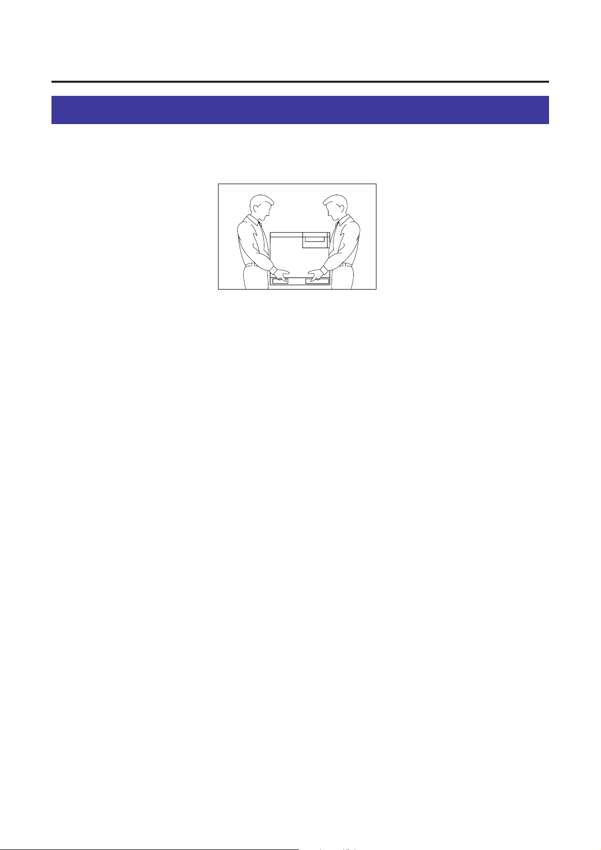
To avoid machine malfunction, do not use the equipment under the following conditions:
Cautions
Before You Start
BLiquids near the equipmentBUnstable or unlevel surfaces BDirectly in front of air
conditioning vents
BDirect exposure to sunlight
BExtremely high or low temperature [temperature range: 10˚C to
32.5˚C (50˚F to 90.5˚F)]
BExtremely high or low humidity (humidity range: 20% to 80% RH)
BCondensation due to rapid change of temperature
BAreas of poor ventilation
BAreas of high dust or chemical
fume concentration (solvent
etc.)
BToo much media/document
which exceeds the limit mark
on the guide of the tray.
BFront/right/left doors opened
while the printer is operating; it
may cause a media jam.
BAny toner other than genuine
Panasonic toner.
It may damage the printer.
Not genuine toner
Page 13
13
Before You Start
■Static Electricity Damage
To prevent static electricity damage to any of the following components, touch a grounded metal surface,
such as the printer’s bare metal frame prior to touching the component.
BThe interface connectors : SCSI, parallel and optional network
BElectrical components, connectors inside the printer and any components on the optional board (RAM
Expansion Board or Ethernet Card)
BThe connector pins on the optional 2nd cassette feeder for the printer
■Interface Cable
Always use a shielded interface cable. Use of an unshielded cable can result in radio interference with data.
■Waste Disposal Method
Waste material may be dumped or incinerated under conditions which meet all federal, state and local
environmental regulations.
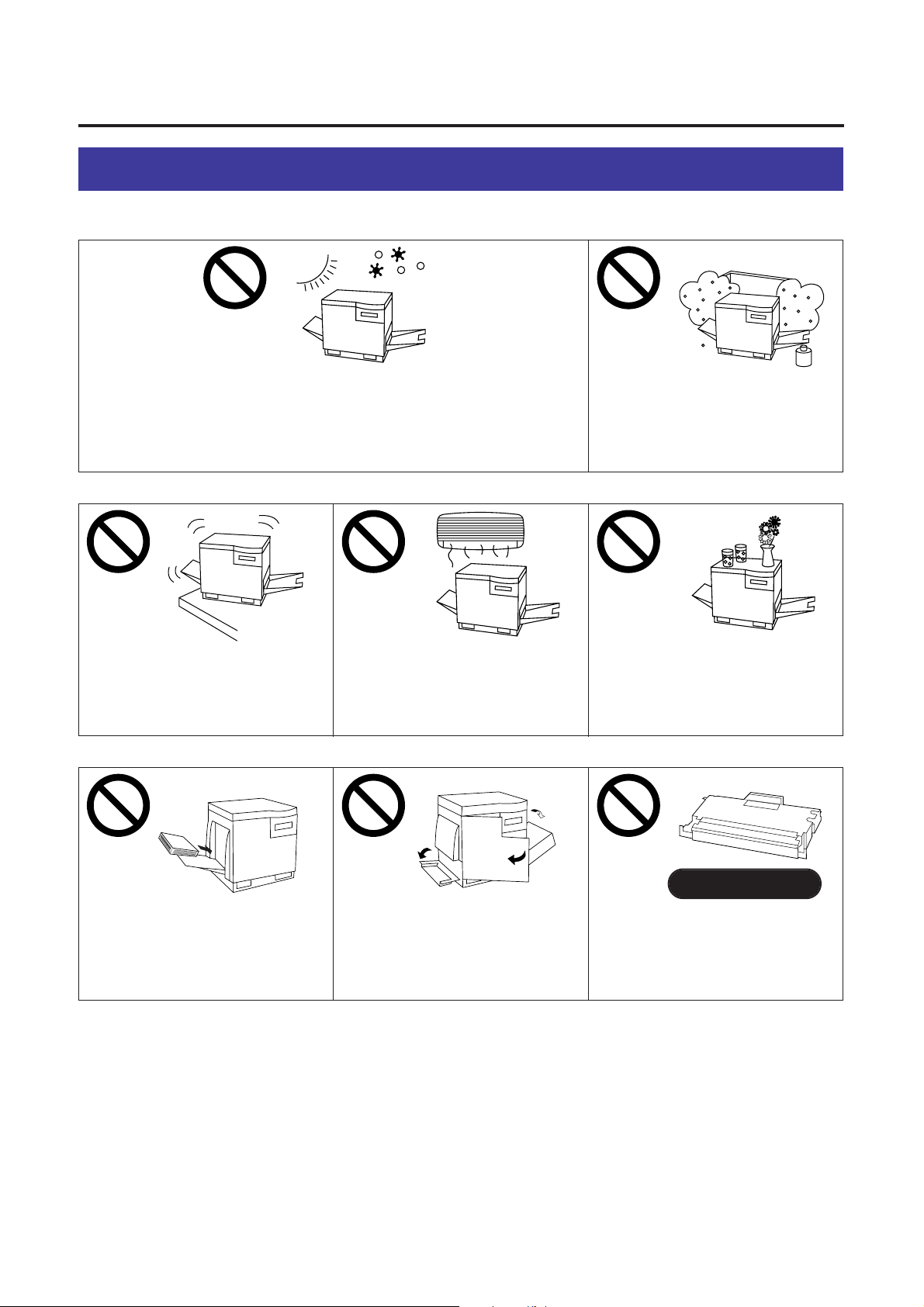
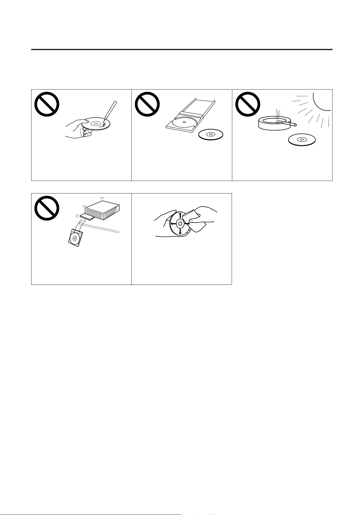
BDo not place heavy objects on
the disc case or drop the case.
BTo clean the disc, hold the disc
by its edges and wipe it from
the center to the edges with a
dry, soft cloth.
BDo not leave the disc in direct
sunlight or near heat sources.
BDo not touch or write on the
surface of the disc.
BDo not leave the disc out of the
protective case.
■CD-ROM
To prevent the CD-ROMs from accidental damages:
Page 14

14
Before You Start
Features
The KX-P8410 Color Laser Printer provides fast, high-quality color printing on plain
paper, plus the ease of operation and high performance you expect from a laser
printer.
Some of its features include:
■High quality
Resolution
Maximum 1200 dpi*
(* with SIMM options installed)
■High speed
Continuous printing on letter size/A4 size paper
Full-color mode: Maximum 3.5 ppm (pages per minute)
Monochrome mode: Maximum 14 ppm
■Easy operation
Printer driver
Easily print full-color documents.
Page 15

One of the following can be used:
■Parallel interface requirement
■SCSI interface requirements
SCSI cable
15
SCSI-2 (FAST SCSI) compatible ( ☞P. 172)
Interface
ASPI manager
ASPI Manager is required.
(Refer to the SCSI-2 board manual.)
Before You Start
System Requirements
PC
Interface
To operate the KX-P8410 effectively, see the following.
CPU: More than Pentium or Pentium PRO
(133 MHz or faster CPU is recommended.)
Operating System: Windows 3.1*1, Windows 95*2or Windows NT 4.0*3 *
4
(Intel Only)
RAM: 16 MB or more (More than 32 MB is recommended.)
Free disk space: 100 MB or more
Virtual memory: 16 MB or more (More than 32 MB is recommended.) for
Windows 3.1 / 95
50 MB or more*5(More than 100 MB is recommended.) for
Windows NT 4.0
Display: Video card that can display more than 256 colors.
(A video card that can display more than 32,000 colors is
recommended.)
Drive: CD-ROM drive
*1Microsoft Windows operating system Version 3.1 (hereafter Windows 3.1)
*2Microsoft Windows 95 operating system (hereafter Windows 95)
*3Microsoft Windows NT Workstation operating system, and Microsoft
Windows NT Server network operating system Version 4.0
(hereafter Windows NT 4.0)
*4Service Pack 3 or later version is required.
*5In the Virtual Memory window, change this setting in the Initial Size box.
SCSI-2 board
ASPI Manager compatible SCSI-2 board
(Adaptec AHA-2940 is recommended.)
Based on the IEEE P1284-C standard
(An ECP compatible parallel port is recommended
for Windows 95. To turn on the ECP mode, use the
computer’s BIOS setup. Refer to the computer’s
manual for details.)
Page 16
16
Before You Start
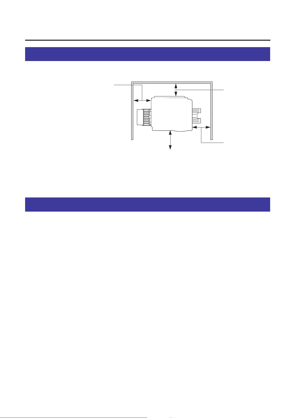
Minimum Space Requirements
Power Source
BThe voltage level of the power source must not vary more than ±10% from the
voltage level marked on the nameplate (located on the back of the unit).
BDo not use an extension cord.
BDo not use a line conditioner, transient suppressor or surge protector as it may
cause a machine error.
Left Right
Rear
35 cm (13.8″)
Controller Board
Opening Space
45 cm (17.7″)
Multi-Purpose Tray
Opening Space
60 cm (23.6″)
Front cover opening space
50 cm (19.7″)
Media tray Opening
Space
Page 17

17
Make sure that all of the items shown below were provided and have not been
damaged. Report damage or shortages to the reseller from which the unit was
purchased. Page 3 includes an area for recording important information such as the
name of reseller, serial number, and date of purchase.
Note:
B
Save the original carton and packing materials for future shipping and
transporting of the unit. They have been specifically designed to protect the
equipment during shipment.
Before You Start
Unpacking
1. Printer (Color imaging unit, Fuser unit, Paper tray and Output tray are included.)
2. Toner cartridges (black, cyan, magenta, and yellow)
3. Power cord
4. KX-P8410 CD-ROM (includes Driver & Utility and Operating Manual)
5. Color Calibration Card
6. Setup manual
123
5
6
4
Page 18
Before You Start
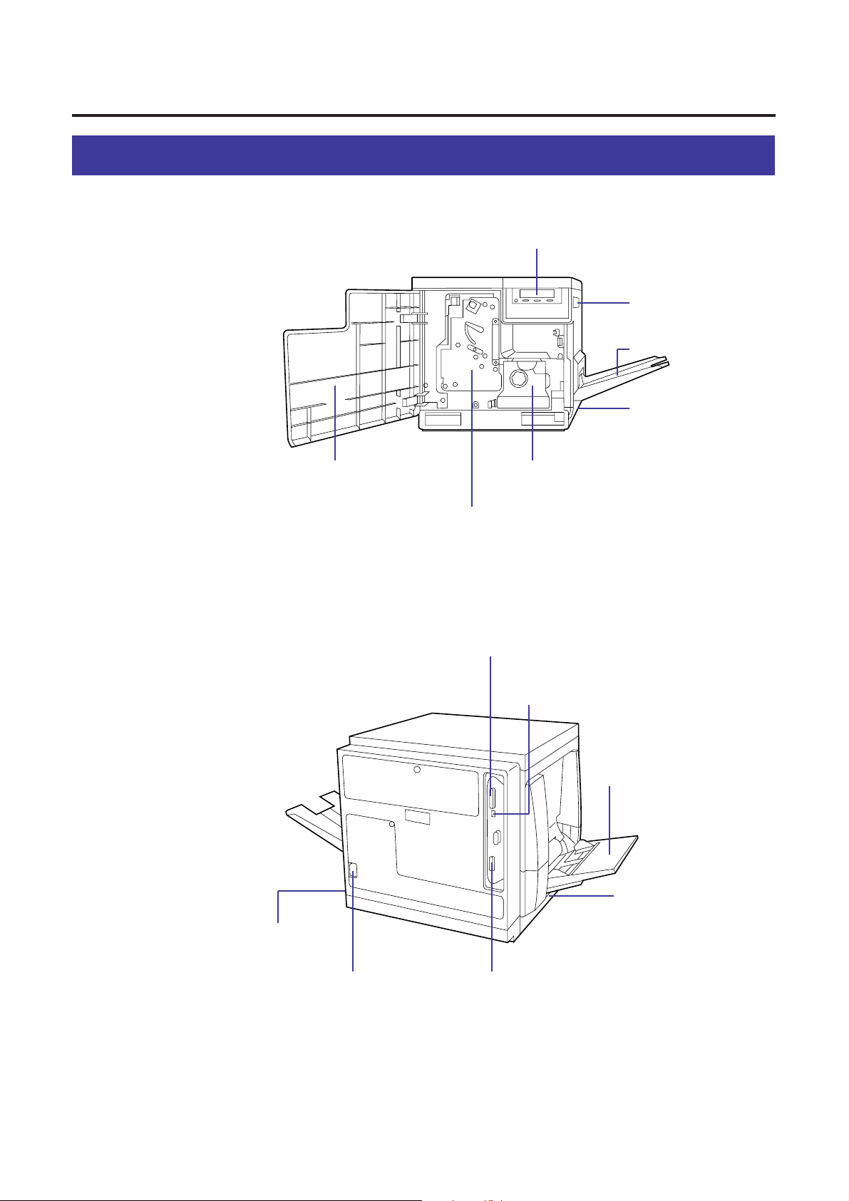
Part Names
■Front side view
Printer panel ( ☞P. 19)
Right side door
( ☞P. 23, 121)
Output tray ( ☞P. 22)
Media tray ( ☞P. 25)
Front door
( ☞P. 21)
■Rear side view
Fuser
( ☞P. 111, 116)
Imaging unit
( ☞P. 21, 110)
SCSI connector ( ☞P. 35)
SCSI ID NO. and
terminator switches ( ☞P. 37)
Multi-purpose tray (MPT)
( ☞P. 29)
18
Power switch
( ☞P. 38)
AC inlet
( ☞P. 34, 36)
Parallel interface
connector ( ☞P. 34)
Left side door ( ☞P. 29)
[Media thickness
switch* ( ☞P. 29)]
* Accessible by opening
the left side door
Page 19
19
MENU
/EXIT
CONTINUE
CANCEL
ENTER
READY
ERORR
Before You Start
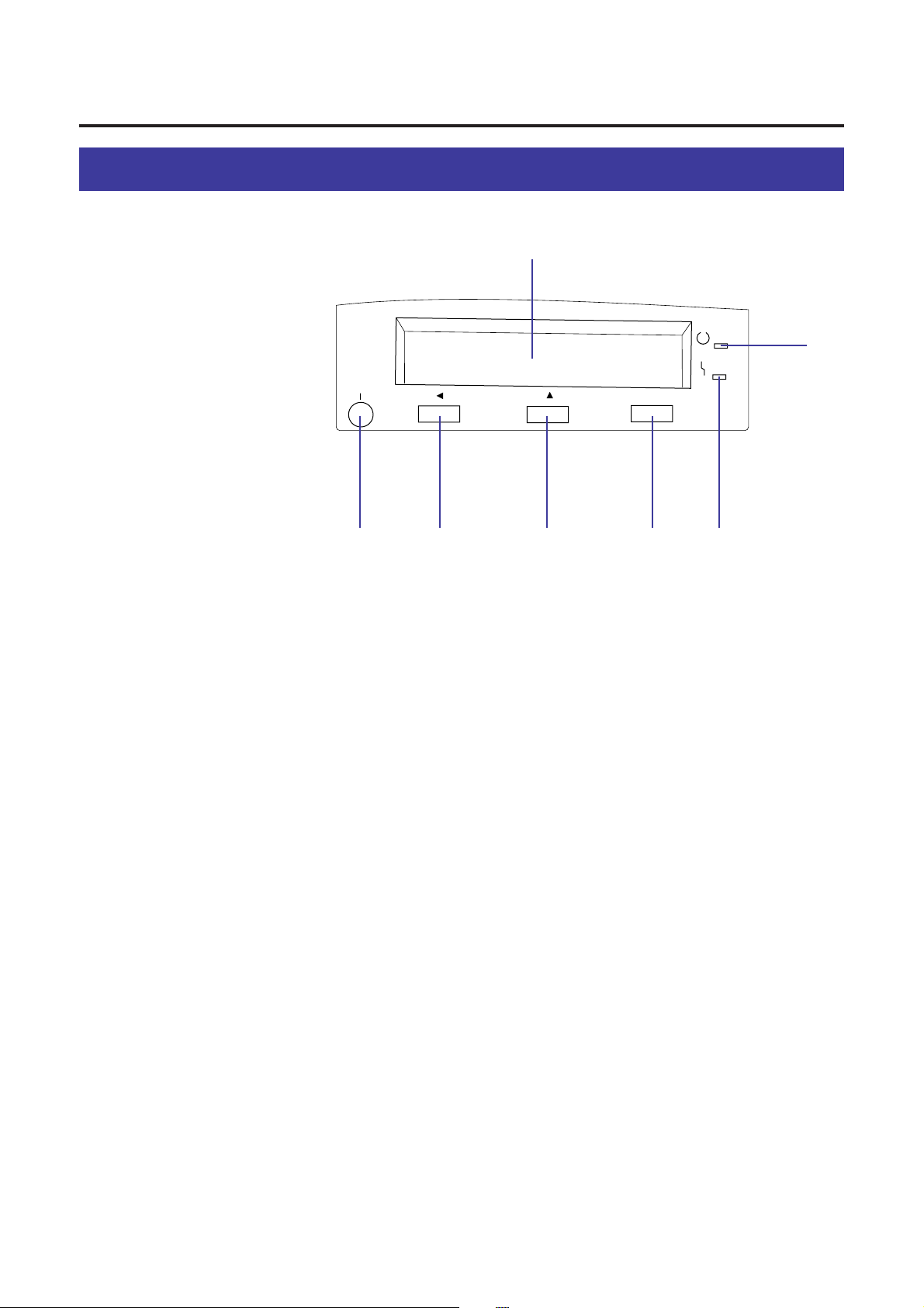
Printer Panel Overview
# LCD (Liquid Crystal Display) panel
The printer LCD has two 24-character lines to display the printer’s status/error
messages or menu settings.
$ MENU/EXIT button
BWhen the printer is ready, pressing this button enters the Menu mode.
BPressing this button exits the Menu mode.
%
II
/CANCEL button
BPressing this button for 2 or more seconds cancels the data in the printer.
BWhen the printer is in the Menu mode, pressing this button:
Displays the previous menu, item or selection.
Decreases the current numerical value of the selection.
Moves the cursor to left.
&
FF
/CONTINUE button
BWhen the printer is in the Menu mode, pressing this button:
Displays the next menu, item or selection.
Increases the current numerical value of the selection.
BWhen error messages such as “Memory Overflow” or “SCSI Communication
Error” are displayed on the LCD, press this button to recover from an error
situation.
' ENTER button
This button is effective only when the printer is in the Menu mode. Pressing
this button:
Enters a sub - menu.
Activates a selection.
$
#
)
%&'(
Page 20

20
Before You Start
( ERROR indicator (orange)
BON: an internal error (Call for Service Error) has occurred.
BBlinking: user correctable error, such as media jam, open door, or a missing
replaceable component (e.g. Toner) has occurred.
) READY indicator (green)
BON: the printer is ready for operation.
BBlinking: the printer is warming up or in the Menu mode.
BBlinking fast: the printer is printing.
Page 21

21
Open the front door.
Turn the upper green lever clockwise until it stops and the arrows
are aligned. (This tightens the internal belts to ready the unit for
printing.)
Close the front door.
Setup
1
2
3
Setting Up the Printer
Preparing the Imaging Unit
Page 22

22
Setup
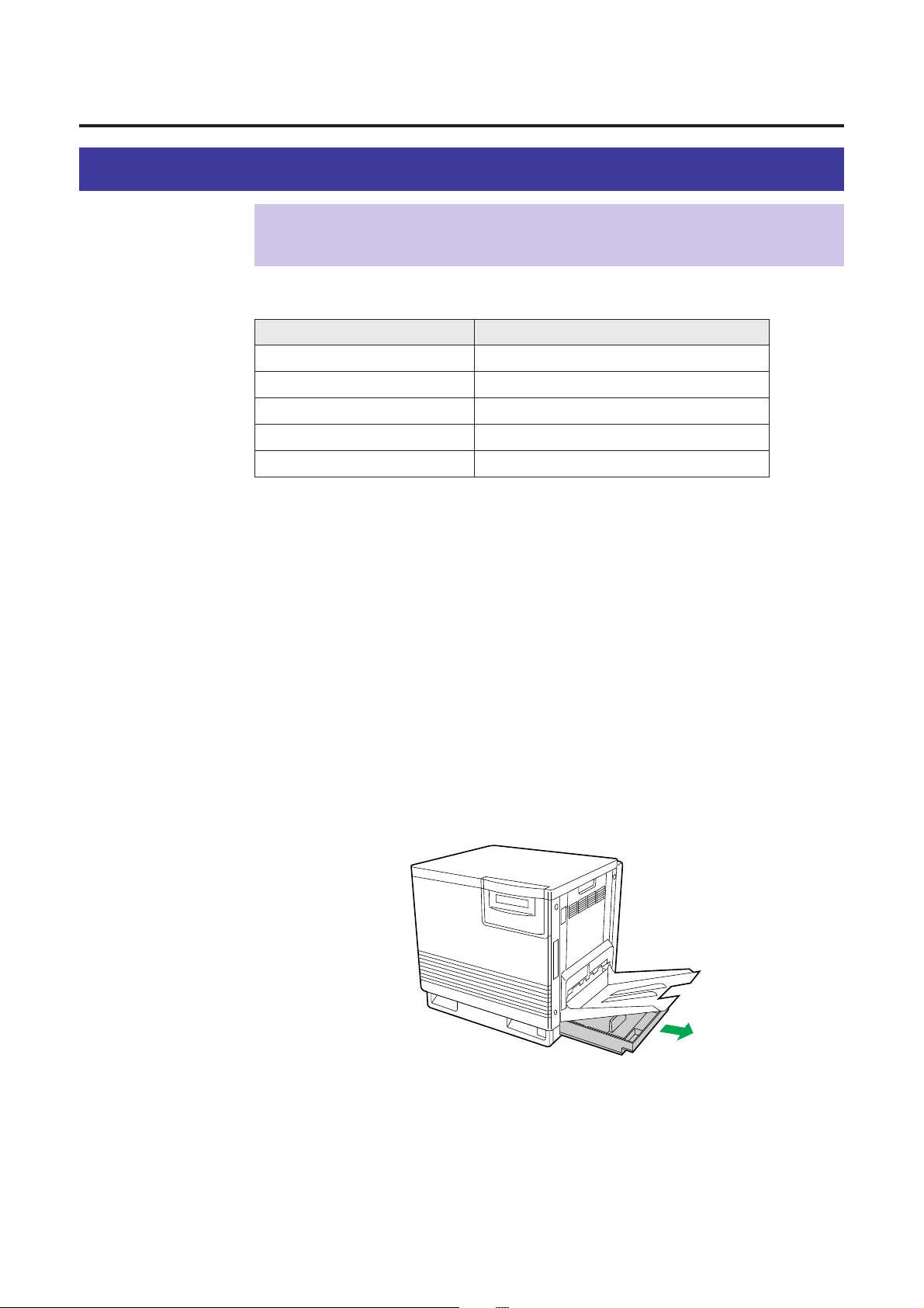
Setting Up the Output Tray
Remove the adhesive tape that holds the output tray against the
printer.
Lower the tray to the operating position.
1
2
Page 23

23
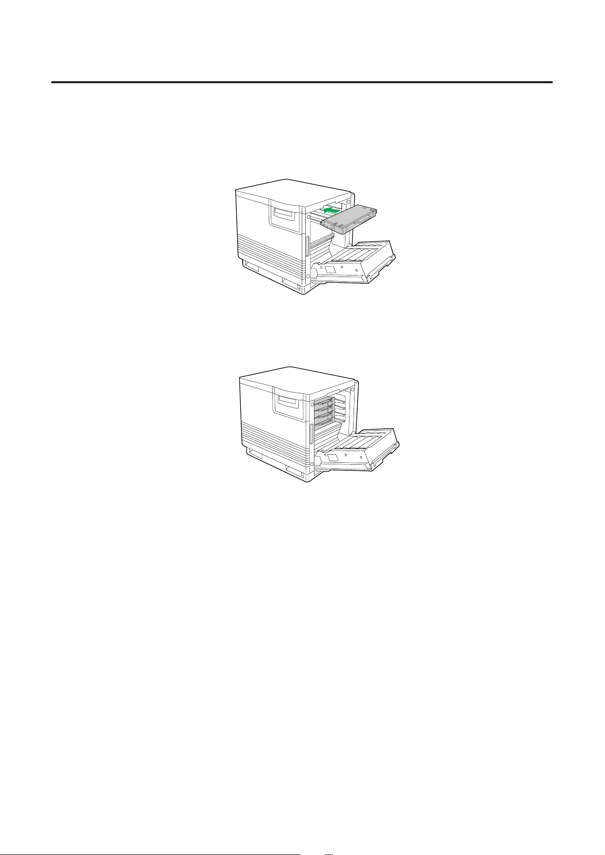
Setup
Installing the Toner Cartridges
Note:
B
The toner cartridges that are shipped with the printer are starter cartridges.
They are installed in exactly the same manner as the optional cartridges; the
only difference is that the starter cartridges have less toner. (The page life
expectancy is 3,000 pages, which is based on a 5% image area.)
Remove the packaging from the toner cartridge.
Remove the shipping cover from the cartridge.
Caution:
B
To avoid possible toner spillage, do not tilt cartridge.
Note:
B
Save all packing material for shipping purpose.
Open the right side door.
Caution:
B
Do not leave the right side door open for more than 1 minute; the imaging unit
will be exposed to light and could be damaged.
1
2
3
Page 24
24
Setup
Insert the toner cartridge in the appropriately labeled slot.
From top to bottom, the order of the color toner cartridges is BLACK, CYAN,
MAGENTA, YELLOW.
Repeat steps 1, 2 and 4 for each toner cartridge.
When you have installed all the toner cartridges, go to step 6.
Close the right side door.
4
5
6
Page 25
25
Legal Paper
Tray Size
A4 Paper
A4 Transparency
Letter Paper
Letter Transparency
210 mm x 297 mm (8.3″ x 11.7″)
210 mm x 297 mm (8.3″ x 11.7″)
216 mm x 279 mm (8.5″ x 11″)
216 mm x 279 mm (8.5″ x 11″)
216 mm x 356 mm (8.5″ x 14″)
The printer is shipped with a media tray (either Letter paper or A4 paper) installed.
Pull the media tray out of the printer.
Remove all packaging materials from inside the media tray; refer
to the instruction sheet attached to the tray.
Setup
Loading Media
Notes:
B
Make sure that you load the correct media. Each tray is designed and labeled
for only paper or transparency. If you load the incorrect media type in a tray, it
may cause a jam.
B
If you have the 2nd Cassette Feeder installed:
If you wish to use the automatic cassette-switching feature (a large print job,
for example), make sure that all trays in the printer are the same media type
and size.
The transparency tray should only be inserted in the upper or middle tray
slots.
1
2
Loading Paper or Transparencies in the Media Tray
The printer uses five different trays:
Page 26

26
Push down on the metal plate until it clicks, locking it in place.
Fan the media (paper/transparencies), then tap it on a level
surface to avoid media jams or skewed printing.
Notes:
B
To optimize your printer’s performance, always use clean, unused media.
B
Be careful not to leave fingerprints on the media, which can result in a smudged
print.
B
Reusing media that has been fed through the printer once (for example, after
jams) can reduce the life of the consumables and paper path components.
B
The recommended transparency is 3M CG3700. If the print quality is poor, print
on the other side.
Setup
3
4
Page 27
27
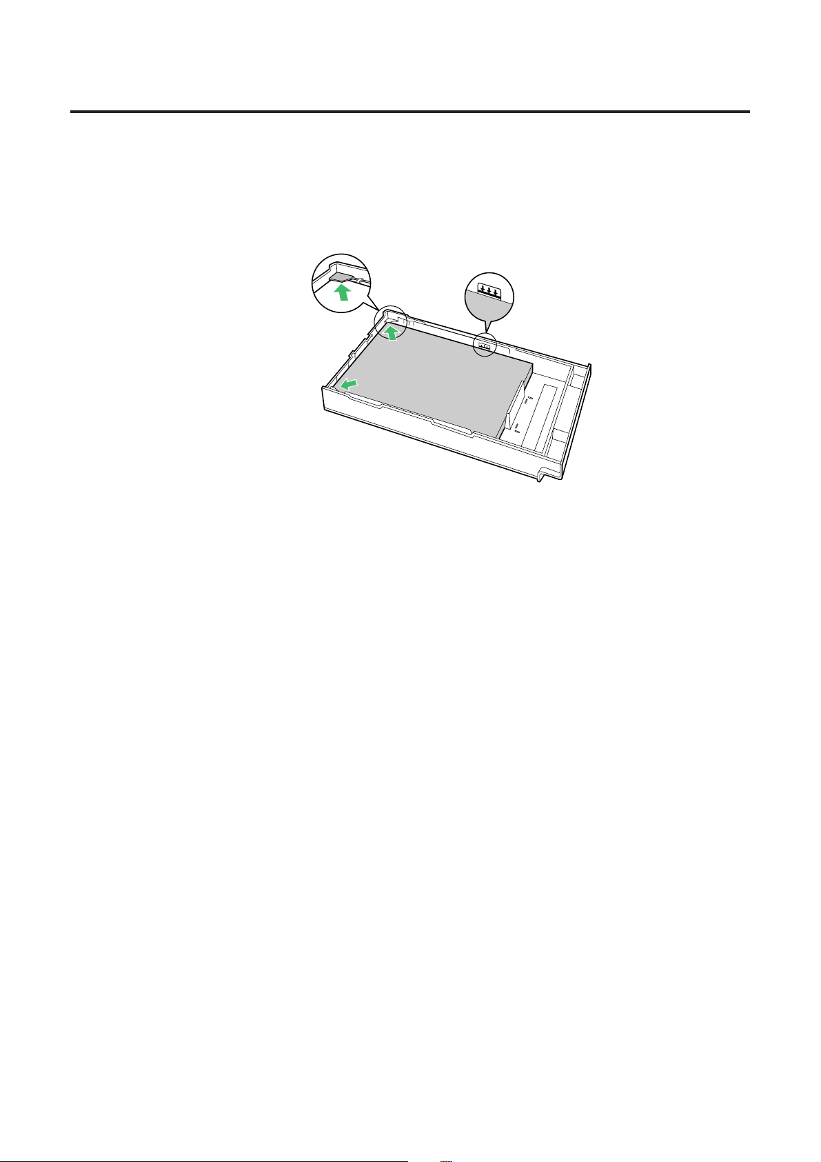
Place the media in the tray under the hooks.
The height of media should not exceed the limit mark on the tray, or it may
cause a jam.
Notes:
B
Load media with the print side down. Most media has instructions
recommending the side to be printed first.
B
Do not mix different types or thicknesses of media in the media tray at one time;
this may cause a jam.
Slide the media tray completely into the slot.
5
6
Setup
Page 28

28
Print area
5.8 mm
(0.23″)
Setup
When the image is printed on the media, the image (print area) is a bit smaller than
the media size. You may need to adjust the page margins in the application software
to match the print area.
The following table and illustrations show the page sizes, the largest print areas, and
the margins for the media sizes supported on this printer.
Margins
Media Page size
Top Bottom Sides
Letter
216 mm x 279 mm
(8.5″ x 11″)
208 mm x 269 mm
(8.2″ x 10.6″)
5.6 mm
(0.22″)
5.6 mm
(0.22″)
3.6 mm
(0.14″)
A4
210 mm x 297 mm
(8.3″ x 11.7″)
200 mm x 287 mm
(7.9″ x 11.3″)
5.1 mm
(0.2″)
4.7 mm
(0.19″)
4.7 mm
(0.19″)
Legal
216 mm x 356 mm
(8.5″ x 14″)
208 mm x 343 mm
(8.2″ x 13.5″)
5.8 mm
(0.23″)
3.6 mm
(0.14″)
Margins and Print Area
208 mm (8.2″) 200 mm (7.9″)
269 mm (10.6″)
287 mm (11.3″)
Letter A4 Legal
208 mm (8.2″)
343 mm (13.5″)
Page 29

The multi-purpose tray (MPT) serves as an additional tray for loading any type of
media that ranges in size from 91 mm x 254 mm to 216 mm x 356 mm (3.6″ x 10″ to
8.5″ x 14″). Use it to load a single sheet or a stack of media. The amount of media
you can load depends upon its thickness.
Use the multi-purpose tray to accomplish the following:
Print on standard and special media
BStandard media
Laser paper [75 to 165 g/m2(20 to 44 lbs.)]
BSpecial media
Labels
Envelope (#10 or larger size)* [Black Text only]
Transparency (The print quality may not be stable. Use the media tray for
best reliability.)
* If the Envelope is larger than #10, you must select a paper size that is larger than
your envelope.
Two-sided printing (double-sided) on laser paper
You should not expect the same print quality and reliability that you get with onesided printing. For details, refer to page 166.
Setting media thickness switch
Because the printer accommodates various media weights from the multi-purpose
tray, media thickness can be manually selected for the most reliable paper-picking.
Follow these steps:
Open the left side door (#). The green media thickness switch is
located on the paper feeder and has three settings:
Move the switch to the desired setting.
Close the left side door.
Laser paper 91 to 123 g/m2(25 to 32 lbs.)
Transparency, Label
29
Setup
1
2
3
Thin
Middle
Thick
Loading Media in the Multi-purpose Tray
Page 30

30
Setup
■Loading Paper, Transparency
Notes:
B
Reusing media that has been fed through the printer (for example, after jams)
can reduce the life of the consumables and paper path components.
B
When printing legal size using the multi-purpose tray, backside marking may
occur. If this occurs, use the legal cassette.
For detailed information on media, refer to page 165.
Set the media thickness switch ( ☞ P. 29).
# Open the Multi-purpose tray.
$ Extend the media support by sliding it outward.
Separate the media guides to the approximate width of the
media.
Fan the media, and then tap it on a level surface to avoid media
jams or skewed printing.
1
2
3
#
$
4
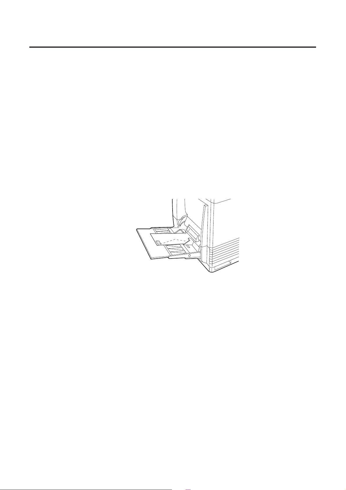
Page 31

31
Insert the media with the printing side up into the multi-purpose
tray.
The height of media should not exceed the limit mark on the left guide, or it
may cause a media jam.
Adjust the media guides to the media size.
Use the printer driver to select the multi-purpose tray.
Setup
5
6
7
Page 32
32
Setup
■Loading an Envelope
Do not insert more than one envelope at a time. Only black text can be printed
on envelopes. For more detailed information on envelopes, refer to page 168
Note:
B
The envelope may be creased when printed.
Set the media thickness switch ( ☞ P. 29).
Adjust the media guides to the width of the envelope.
Insert the envelope with the short end entering the printer first
and the printing side facing up. The edge where the stamp is
located enters the printer last.
Use the printer driver to select Envelope in the Paper size menu
and the Paper source menu.
■Loading Labels
For detailed information on labels, refer to page 167.
Set the media thickness switch ( ☞ P. 29).
Adjust the media guides to the width of the label sheets.
Insert the label sheets in the multi-purpose tray with the printing
side up and the top of the sheets enter first.
The height of labels should not exceed the limit mark on the guide.
Use the printer driver to select Label.
1
2
4
1
2
4
3
3
Page 33

33
Only one PC can be directly connected to your printer.
Setup
Connecting the Printer to a Computer
Page 34

34
If you do not have a parallel interface cable, you will need to purchase one from your
local computer store or dealer ( ☞ P. 171 for Parallel Interface specifications).
Make sure the computer, printer and the other connected
peripheral devices are turned off.
Connect the parallel interface cable to the computer’s parallel
interface connector and the printer’s parallel interface connector.
Notes:
B
The actual connector on the computer may differ depending on the
manufacturer of the computer.
B
If the cable is connected to the PC via a printer buffer or selector, the printer
may not print.
Connect the power cord to the printer’s AC inlet and to an AC
outlet.
Setup
1
2
3
Computer’s parallel
interface connector
Using a Parallel Interface Cable
Page 35

35
Note for Terminator setting:
B
The printer must be the last device in the chain. The terminator setting of all
other devices in the chain must be off.
Make sure the computer, printer and the other connected
peripheral devices are turned off.
Connect the SCSI cable to the computer’s SCSI connector and
the printer’s SCSI connector.
BA SCSI-2 board must be installed in the computer.
If you do not have a SCSI-2 board or a SCSI interface cable, you will need to
purchase one from your local computer store or dealer ( ☞ P. 15, 172 “SCSI
Interface” specifications).
Make sure the SCSI ID No. of the printer is 1 (default setting).
BIf you have other devices connected to the computer, make sure that each
SCSI device has a different ID No.
BTo change the printer’s ID No., use the ID No. switches (#1, #2, #3) located
on the back of the printer. Also refer to Table 1 on page 37.
1
2
3
1234
ON
Setup
Computer’s SCSI
connector
Using a SCSI Cable
Page 36

36
Make sure the terminator switch (#4) of the printer is set to ON
(default setting).
Connect the power cord to the printer’s AC inlet and to an AC
outlet.
4
5
Setup
Page 37

37
■Setting the SCSI ID Number
In most cases, there is no need to change the default settings.
However, if you have other peripheral devices connected in a SCSI chain, check if
their ID numbers conflict with that of the printer. Be sure to choose an unassigned ID
number.
ID number can be changed by using the SCSI ID No. switches (#1, #2, #3) [ ☞ Table
1 below].
Table 1
■Setting the Terminator
The terminator setting can be changed by using the terminator switch (#4).
Terminator ON:
Terminator OFF:
Setup
1234
ON
1234
ON
ID No.
SCSI ID No. switches
#3
0
1
2
3
4
5
6
7
#1
OFF
ON
OFF
ON
OFF
ON
OFF
ON
#2
OFF
OFF
ON
ON
OFF
OFF
ON
ON
OFF
OFF
OFF
OFF
ON
ON
ON
ON
SCSI ID No.
switches
Terminator switch
ON
1234
Page 38

38
Turn ON the printer, then the computer.
# The READY indicator on the printer starts flashing and
“Initializing” is displayed on the printer LCD panel.
$ After approximately 3.5 minutes, the printer’s READY indicator
is illuminated and “Ready” is displayed on the printer LCD
panel.
The printer is ready for printing.
Note:
B
When you power on your system for the first time, if “New Hardware Found” is
displayed on the computer screen, refer to page 43
.
Setup
Power On
1
2
Page 39

39
Setup
Printing a Test Page From the Printer Panel
The test page provides general information on printer settings and configuration.
Make sure the printer is ready and paper is loaded. Use the following procedure to
print a test page.
Press the MENU/EXIT button to enter the Menu Mode.
Press the ENTER button.
Press the ENTER button again.
The printer will start printing a configuration page:
1
2
3
Menu Mode
Test Page
Test Page
Configuration Page
Panasonic Color Laser Printer
Model Name
Printer Rom Version No.
Installed Memory
Installed Cassette
< Panel Settings >
System Setting
Maintenance
Color Calibration
: KX-P8410
:
VXXX : M8XXXX (R019)
: 008 MBytes
:
Media Tray - Letter
Energy Star
on
Auto Continue
off
Data Time Out off
Page Count 0000000000
Color Imaging Unit
000%
Transfer Unit 000%
Fuser Unit
000%
Oil Supply Roll 000%
OFFSET
00
CYAN
00
MAGENTA
00
YELLOW 00
BLACK 00
(C) 1996-1998 Kyushu Matsushita Electric Co.,Ltd.
(Example)
Page 40

40
Setup
Installing the KX-P8410 Software
The KX-P8410 software installation will create the following.
BPrinter driver for Windows 3.1, Windows 95 or Windows NT 4.0 ( ☞ P. 41, 42, 45)
BStatus Display for Windows 3.1, Windows 95 or Windows NT 4.0 ( ☞ P. 152)
Note:
B
If you are using Windows 3.1, disable or uninstall any application software’s
printer status to prevent conflicts with the KX-P8410 Status Display for
Windows 3.1.
B
When reinstalling the KX-P8410 software, do it immediately after restarting
Windows.
Page 41

41
Setup
Start Windows 3.1.
Quit all applications.
Insert the KX-P8410 CD-ROM into your computer’s CD-ROM
drive.
Click File from the Program Manager, then click Run... .
Click Browse and select your CD-ROM drive from the [Drives:]
box.
Select Setup.exe, and click OK .
Click OK .
The Installer starts.
Follow the instructions on the screen to complete the installation.
1
2
3
Installing the Printer Driver and Utilities for Windows 3.1
4
5
6
7
8
Page 42

42
Start Windows 95.
Quit all applications.
Click Start , move the pointer to Settings, then click
Control Panel.
The Control Panel window is displayed.
Double click Add/Remove Programs .
The Add/Remove Program Properties window is displayed.
Click Install .
The Install Program From Floppy Disk or CD-ROM window is displayed.
Insert the KX-P8410 CD-ROM into CD-ROM drive.
Click Next> .
The Run Installation Program window is displayed.
Click Finish .
Wait until the Panasonic KX-P8410 Utilities Welcome window is displayed.
Follow the instructions on the screen to complete the installation.
After installation, restart your system.
Note:
B
During installation, when “Setup is adding icon to the Printer folder. Please wait
several minutes” is displayed, the processing may take approximately 5 to 10
minutes to complete depending on the system.
7
4
5
6
8
1
2
3
Setup
Installing the Printer Driver and Utilities for Windows 95
9
Page 43

43
Setup
■Using Plug and Play
Turn on the printer.
Turn on the computer and start Windows 95.
The New Hardware Found window is displayed for a few seconds, then the
Update Device Driver Wizard window is displayed.
Insert the KX-P8410 CD-ROM into CD-ROM drive.
Click Next> .
“Windows was unable to locate a driver for this device” is displayed.
Click Other Locations... .
Type in your CD-ROM drive name followed by :\Win95\Disk2
(example; D:\Win95\Disk2) in the Location field and click
OK .
Click Finish .
The Insert Disk window is displayed.
Click OK .
The Copying Files window is displayed.
Type in your CD-ROM drive name followed by :\Win95\Disk2
(example; D:\Win95\Disk2) in the Copy File from field and click
OK .
Click OK .
The Select SETUP.EXE window is displayed.
Click OK . Select SETUP.EXE included on the KX-P8410 CD-
ROM in your CD-ROM drive and then click Open .
Wait until the Panasonic KX-P8410 Utilities Welcome windows is displayed.
Follow the instructions on the screen to complete the installation.
After installation, restart your system.
Note:
B
The Plug and Play installation procedure varies depending on the version of
Windows 95. Refer to Help in Windows 95.
1
2
7
3
4
5
6
8
9
10
11
12
Page 44

44
Setup
■Using Add Printer
Start Windows 95.
Quit all applications.
Click Start , move the pointer to Settings, then click Printers.
The Printers window is displayed.
Double click the Add Printer icon.
Install the KX-P8410 CD-ROM into CD-ROM drive.
Click Next> .
Select Local printer or Network printer and then click Next> .
Click Have Disk... .
Type in your CD-ROM drive name followed by :\Win95\Disk2
(example; D:\Win95\Disk2) in the Install From disk field and
click OK .
Click Next> .
Follow the instructions on the screen to complete the installation.
After installation, restart your system.
Notes:
B
The above “Using Add Printer” procedure installs only the printer driver. It does
not install the Status Display program.
B
After installing the printer driver, it will take several minutes for the printer to
register and display in Printers Folder.
1
2
7
3
4
5
6
8
9
10
11
Page 45

45
Start Windows NT 4.0.
Quit all applications.
Click Start , move the pointer to Settings, then click
Control Panel.
The Control Panel window is displayed.
Double click Add/Remove Programs .
The Add/Remove Program Properties window is displayed.
Click Install .
The Install Program From Floppy Disk or CD-ROM window is displayed.
Insert the KX-P8410 CD-ROM into CD-ROM drive.
Click Next> .
The Run Installation Program window is displayed.
Click Finish .
Wait until the Welcome window is displayed.
Click Next> .
The Choose Destination Location window is displayed.
Click the type of setup, then click Next> .
The Select Program Folder window is displayed.
Click Next> .
The Start Copying Files window is displayed.
7
4
5
6
8
1
2
3
Installing the Printer Driver and Utilities for Windows NT 4.0
9
Setup
10
11
Page 46

46
Setup
Click Next> .
After copying files, the Add Printer Wizard window is displayed.
Click Next> .
Select LPT port by clicking on the check box.
Click Next> .
Click Have Disk... .
The Install From Disk window is displayed.
Click Browse... .
Click Cancel .
The Locate File window is displayed.
Select CD-ROM drive.
Open Winnt40, Disk2, then select Pgdinta.inf file.
Click Open .
Follow the instructions on the screen to complete the installation.
BTo connect the printer to a SCSI port, the SCSI port needs to be installed.
Refer to the Ports tab of the Panasonic KX-P8410 Properties window
( ☞ P. 88 to 91).
12
13
14
15
16
17
18
19
20
21
22
Page 47

47
Setup
Installing the SCSI Port:
Notes:
B
It is recommended that you do not connect the printer directly to the file server.
Otherwise the printer and server performance may be diminished.
B
When printing through the SCSI port, the access speed between other
connected SCSI devices is diminished.
B
To connect the KX-P8410 to your SCSI port, a SCSI driver and ASPI Manager
must be installed. Refer to your SCSI board manual.
Click Start , select Settings, then click Printers.
Click the Panasonic KX-P8410 icon.
Click the File menu, then click Properties.
The Panasonic KX-P8410 Properties window is displayed.
Click the Ports tab.
Click Add Port... .
The Printer Ports window is displayed.
Click New Monitor... .
The Installing Print Monitor window is displayed.
Insert the KX-P8410 CD-ROM into CD-ROM drive.
Click Browse... .
Click Cancel .
The Locate File window is displayed.
Note:
B
The SCSI port cannot be installed through the Monitor.inf file when copied to a
directory with long file name.
4
5
1
2
3
7
6
8
9
Page 48

48
Setup
Select CD-ROM drive.
Open Winnt40, Disk2, then select Monitor.inf file.
Click Open .
The Installing Print Monitor is displayed.
Click OK .
The Printer Ports window is displayed.
Click New Port.... .
The Port Name window is displayed.
Type the port name (for example; KXP8410GDI), then click OK .
The Printer Ports window is displayed.
Click Close .
10
15
14
11
12
13
Page 49

49
Setup
■Using the Printer in a Network Environment
For the server computer:
To share the printer with other clients on the network, perform the following steps
after installing the printer driver.
Double click the My Computer icon.
Double click the Printer icon.
Select the Panasonic KX-P8410 printer.
Click File menu, then click Sharing... .
Click Shared.
Enter the printer name (ex. KX-P8410).
If the shared printer is used through Windows 95, the printer name must not
exceed 12 characters.
Click OK .
4
5
1
2
3
6
7
Page 50

50
Setup
For a client computer:
To use the printer connected to the server, perform the following steps after installing
the printer driver.
< For Windows NT 4.0 Users >
Click Start , move the pointer to Settings and click Printers.
Double click the Add Printer icon.
Select Network printer server.
Click Next> .
Select the Panasonic KX-P8410 printer in the Shared Printers
box.
Click OK and follow the instructions on the screen.
Click Finish .
< For Windows 95 Users >
Double click the My Computer icon.
Double click the Printers icon.
Double click the Add Printer icon.
Click Next> .
1
2
3
4
5
6
1
2
3
4
7
Page 51

51
Setup
Click Network printer, then click Next> .
Click Browse... .
Select the KX-P8410 printer.
Click OK .
Click Next> .
If the server does not have the Printer Driver for Windows 95, click
Have Disk... .
The Install From Disk window is displayed.
Click Browse... .
Insert the KX-P8410 CD-ROM into CD-ROM drive.
Select the CD-ROM drive.
Open Win95, Disk2, then select KXP8410.inf file. Click Open .
The Printer Drivers for Windows 95 window is displayed.
Click OK .
The Install From Disk window is displayed.
Click OK .
Click Next> .
Click Finish .
5
6
7
8
9
10
11
12
13
14
15
16
17
Page 52

52
Setup
■Removing the Printer Driver
Click Start , move the pointer to Settings and click Printers.
Select Panasonic KX-P8410.
Click File menu, then click Delete.
Click Yes .
1
2
3
4
Page 53

53
Setup
If you need to remove the KX-P8410 software, perform the following steps.
■For Windows 3.1 users:
From the Program Manager double click the Panasonic
KX-P8410 Utilities icon.
Double click the Uninstall Utilities icon.
Click Yes .
Follow the instructions on the screen.
■For Windows 95 / Windows NT 4.0 users:
Click Start , move the pointer to Programs, then to
KX-P8410 Utilities.
Click Uninstall .
Click Yes .
Follow the instructions on the screen.
Note:
B
For removing the Panasonic KX-P8410 icon in the Printer Folder, refer to Help
in Windows 95 / Windows NT 4.0.
1
2
1
2
3
4
Removing the KX-P8410 Software
3
4
Page 54

54
Setup
Installing Panasonic Font Manager
The Panasonic Font Manager is included in the KX-P8410 CD-ROM.
To install the above application, perform the following steps.
■For Windows 3.1 users:
Start Windows 3.1.
Quit all applications.
Insert the KX-P8410 CD-ROM into your computer CD-ROM drive.
Click File from the Program Manager, then click Run... .
Click Browse and select your CD-ROM drive from the [Drives:]
box.
Select Install.exe in the Font directory, and click OK .
Click OK .
The installer starts.
Follow the instructions on the screen to complete the installation.
1
2
3
4
5
6
7
8
Page 55

55
Setup
■For Windows 95 / Windows NT 4.0 users:
Start Windows 95 / Windows NT 4.0.
Quit all applications.
Insert the KX-P8410 CD-ROM into your computer CD-ROM drive.
Click Start , move the pointer to Run..., then click Run .
Click Browse and select your CD-ROM drive.
Select Install.exe in the Fonts folder, and click OPEN .
Click OK .
The installer starts.
Follow the instructions on the screen to complete the installation.
Note:
BWhen you insert CD-ROM into your drive, application installer may start
automatically. In this case, quit the Panasonic quick installer and use the
application installer.
For information on how to use the applications, refer to their manuals.
1
2
3
4
5
6
7
8
Page 56

56
The printer panel provides an interface to adjust the density of the toner applied to
the media. This feature compensates for the changes in density that can occur as
environmental conditions changes, toner cartridges or the imaging unit age.
Perform the following steps to adjust the color density:
To print a Color Calibration Page:
# Press the MENU/EXIT button on the printer panel.
$ Press the F button.
% Press the ENTER button.
& Press the F button 5 times and the following is displayed.
' Press the ENTER button.
A Color Calibration Page will be printed.
1
Setup
Setting the Color Density
Menu Mode
Test Page
Menu Mode
Color Calibration
Color Calibration
Calibration Offset
Color Calibration
Calibration Test Print
FI
MENU/EXIT ENTER
MENU
/EXIT
CANCEL
READY
ERORR
ENTER
CONTINUE
Page 57

57
Setup
Color Calibration Page (Example):
The current density setting for each color is indicated by the line enclosure on the
Color Calibration Page as shown in the following example.
The factory default setting for each color density is 0.
Current color
density settings
Page 58

58
Setup
Compare the current color density settings on the Color
Calibration Page with the color density samples on the Color
Calibration Card to see if they match.
Place the Color Calibration Page on at least 2 sheets of clean white paper in a
well-lighted area.
BIf they match, then you do not need to adjust the color density
and you may proceed with any operation you wish to perform.
BIf they do not match, go to step 3.
Determine which block on the Color Calibration Page most
closely matches the density of the cyan sample on the Color
Calibration Card.
BRepeat step 3 for each color.
2
3
Color Calibration
Card
Color Calibration
Page
Page 59

59
Setup
If you wish to adjust the density for all colors simultaneously,
perform the following, then go to step 5.
# Repeat instructions # through % of step 1 on page 56.
$ Press the ENTER button.
% Press the F/I button to darken/lighten all the colors.
Pressing the F/I button twice selects the next/previous level settings.
(For example:)
BIf you wish to make the density setting darker by 2 levels:
Press the F button 4 times.
BIf you wish to make the density setting lighter by 1 level:
Press the I button 2 times.
& Press the ENTER button.
' Press the F button 4 times and the following is displayed.
Color Calibration
Calibration Offset
Calibration Offset
0* (-5 to 5)
Color Calibration
CYAN
Color Calibration
Calibration Test Print
4
A
Page 60

60
If you wish to adjust the density for each color independently,
perform the following, then go to step 5.
# Repeat instructions # through % of step 1 on page 56.
$ Press the F button.
% Press the ENTER button.
& Press the F/I button to darken/lighten the cyan color.
Pressing the F/I button twice selects the next/previous level setting.
(For example:)
BIf you wish to make the density setting darker by 4 levels:
Press the F button 8 times.
BIf you wish to make the density setting lighter by 2 levels:
Press the I button 4 times.
' Press the ENTER button.
( Repeat instructions % through ' for each color
(MAGENTA, YELLOW, BLACK).
BTo skip a color, press the F button.
BTo return to a previous color, press the I button.
BBefore going to step 5, make sure the following is displayed.
Press the ENTER button to reprint the Color Calibration Page.
BThe line enclosure reflects the changes made to the settings.
BIf you are not satisfied with the current color density settings, repeat steps 4
and 5 above.
Notes:
B
The color density setting affects the average life of toner.
B
Save the Color Calibration Card for future calibrations.
Color Calibration
CYAN
Color Calibration
Calibration Test Print
CYAN
0* (-10 to 10)
Color Calibration
MAGENTA
4
B
5
Setup
Page 61

61
Main Menu
Using the Printer
Menu Mode
The Menu mode includes a Main menu, Item menu, Selection 1 menu and Selection
2 menu which can be changed from the printer panel.
When Ready is displayed in the upper line of the LCD, pressing the MENU/EXIT
button will allow you to enter the Menu mode.
Once in the Menu mode:
BPress the F/CONTINUE button to:
Display the next menu.
Display the next item.
Increase the numerical value of the selection by 1 or display the next selection.
BPress the I/CANCEL button to:
Display the previous menu.
Display the previous item.
Decrease the numerical value of the selection by 1 or display the next selection.
BPress the ENTER button to:
Enter a sub - menu.
Activate a selection.
Print a Configuration/Maintenance/Color Calibration Page.
Before you attempt to change any settings, check the factory default settings in the
following table. For details on changing the settings, refer to Outline for Operation
(☞ P. 64).
Once you have changed the printer panel settings, they are automatically saved as
user default settings even if the power is turned off.
Item Menu
Test Page
Selection 2 MenuSelection 1 Menu
Configuration Page
Calibration Offset
CYAN
MAGENTA
YELLOW
BLACK
Calibration Test Print
Reset Calibration
0*1(-5 to 5)
0*1(-10 to 10)
0*1(-10 to 10)
0*1(-10 to 10)
0*1(-10 to 10)
YES
NO
Color Calibration
(continued)
*1Factory default setting
Maintenance Page
CYAN
MAGENTA
YELLOW
BLACK
Page 62

62
Usage=xx%
Outline for Menus
Test Page
Prints the Configuration Page and Maintenance Page.
■Configuration Page
Prints general information on printer settings and configuration.
■Maintenance Page
Prints each color (Cyan, Magenta, Yellow or Black) halftone to check for print
quality.
Color Calibration
Adjusts the toner density for each color independently or all colors.
■Calibration Offset
Adjusts the density for all colors (CYAN, MAGENTA, YELLOW and BLACK).
Setting a higher number provides darker colors and setting a lower number
provides lighter colors.
■CYAN / MAGENTA / YELLOW / BLACK
Adjusts the density for each color independently. Setting a higher number provides
darker color and setting a lower number provides lighter color.
Using the Printer
xxxxxx
Usage=xx%
Usage=xx%
Usage=xx%
Page Count
Imaging Unit
Transfer Unit
Fuser Unit
Oil Roll
Maintenance
Item Menu Selection 2 MenuSelection 1 Menu Main Menu
*1Factory default setting
*2This menu appears when the optional network card is installed.
Energy Star
Auto Continue
ON*
1
Data Timeout
System Setting
OFF
ON
OFF*
1
ON 30*1(30 to 240s)
OFF*
1
IP Address xxx.xxx.xxx.xxx
xxx.xxx.xxx.xxx
xxx.xxx.xxx.xxx
Network *
2
Subnet Mask
Default Gateway
Page 63

63
■Calibration Test Print
Prints a Color Calibration Page with the current density settings.
■Reset Calibration
Setting YES resets the current settings back to the default settings.
Note:
B
The color density setting affects the average life of toner.
System Setting
Configures the printer.
■Energy Star
To conserve energy and operating cost, this printer is provided with a
programmable power save feature. Printer is factory set with the power save
feature turned on.
If Energy Star is enabled, the printer enters the Energy Star mode when the printer
is idle for 30 minutes.
■Auto Continue
With the Auto Continue set to ON, the printer automatically recovers from the
following error condition if no recovery operation is done for 10 seconds.
BMemory Overflow
■Data Timeout
With the Data Timeout set to ON, the printer automatically returns to Ready status if
the printer does not receive any data from a computer within the time period set in
this selection (30 to 240 seconds).
Network
Sets the addresses used in TCP / IP Protocol. During setting, use the I/CANCEL
button to move the cursor and the F/CONTINUE button to increase the numerical
value.
Maintenance
Displays the page count of the printer and the consumption of supplies. It also gives
you an idea when the following supplies need to be replaced. The following table
shows the average life of each supply, which is based on a 5% image area and
standard density. Refer to pages 110 and 111 for details.
*1When a supply is replaced with a new one, the printer will automatically reset the
page counter for that supply to 0.
*2Transparencies, coated paper and other specialty media will result in shortening
the life of a consumable.
Using the Printer
Average life
15,500 pagesOil Supply Roll
*
1
Supplies
Imaging Unit
*
1
Monochrome (60,000 pages)
Transfer Unit 80,000 pages
Fuser Unit
*
1
31,000 pages
*
2
Color (15,000 pages)
Page 64

64
Printer Panel
Press the MENU/EXIT button to enter the Menu mode.
Press the F/I button until the desired menu is displayed.
Press the ENTER button to enter the item menu.
Press the F/I button until the desired item is displayed.
Press the ENTER button to enter the Selection 1 menu.
BIf you have selected Configuration Page or Calibration Test Print in step 4,
the printer will exit the Menu mode after printing the page.
Press the F/I button to increase/decrease the numerical value
or display the desired selection.
Press the ENTER button to activate your selection and advance
to the next item in the same menu that you selected in step 2.
BIf you have selected Maintenance Page in step 4, the printer will exit the
Menu mode after printing a maintenance page in the selected color.
BIf you have selected Data Timeout in step 4, you will enter the Selection 2
menu. Press the F/I button to increase/decrease the data time out, then
press the Enter button to activate your selection and exit the Menu mode.
Using the Printer
Outline for Operation
1
2
3
4
5
6
7
MENU
/EXIT
CONTINUE
CANCEL
ENTER
READY
ERORR
FI
MENU/EXIT ENTER
Page 65

65
Using the Printer
If you wish to set more items in the same menu, repeat steps 4 to
7 above.
BTo exit the Menu mode at any stage, press the MENU/EXIT button.
BTo change the setting of an item of a different menu, first exit the Menu
mode, then repeat steps 1 to 8 above.
8
Page 66

66
The KX-P8410 window can be displayed from Windows ( ☞below) or from an
application ( ☞P. 68).
Note:
B
Available option tabs and operation buttons displayed through Windows 95 are
different from those displayed through Windows 3.1.
Choosing Printer Properties Under Windows:
■For Windows 95
Click Start , select Settings, then click Printers.
The Printers window is displayed.
Click the
Panasonic KX-P8410
icon.
Click the File menu, then click Properties.
The Panasonic KX-P8410 Properties window is displayed.
Using the Printer
Displaying the Panasonic KX-P8410 Window
(for Windows 95 / 3.1)
A
2
1
3
Page 67

67
Click a tab to view the features.
Details Tab ( ☞P. 69)
Paper Tab ( ☞P. 70)
Quality Tab ( ☞P. 72)
Option Tab ( ☞P. 74)
Memory Tab ( ☞P. 76)
■For Windows 3.1
Double-click
Main
icon and
Control Panel
icon, then double-click
Printers
icon.
The Printers window is displayed.
Select Panasonic KX-P8410 on LPT1S, then click Setup .
The Panasonic KX-P8410 window is displayed.
S
The port name (LPT1) may vary depending on the connection of your printer.
4
Using the Printer
1
2
Page 68

68
Using the Printer
Click a tab to view the features.
Paper Tab ( ☞P. 70)
Quality Tab ( ☞P. 72)
Option Tab ( ☞P. 74)
Memory Tab ( ☞P. 76)
From an application
For example, to print a document created in Microsoft WordPad in Windows 95,
perform the following steps.
Click Start , select Programs, select Accessories, then click
WordPad.
The WordPad window is displayed.
Click the File menu, then click Print... .
The Print window is displayed.
Select Panasonic KX-P8410 in the Name : box.
Click Properties .
The Panasonic KX-P8410 window is displayed.
Click a tab to view the features.
Paper Tab ( ☞P. 70)
Quality Tab ( ☞P. 72)
Option Tab ( ☞P. 74)
Memory Tab ( ☞P. 76)
Note:
B
The print options in the File menu depend on the Windows application. Refer to
the application manual.
B
2
1
3
4
The instructions described hereafter are based on Windows 95. However,
most instructions for Windows 3.1 are the same as Windows 95.
5
3
Page 69
69
Using the Printer
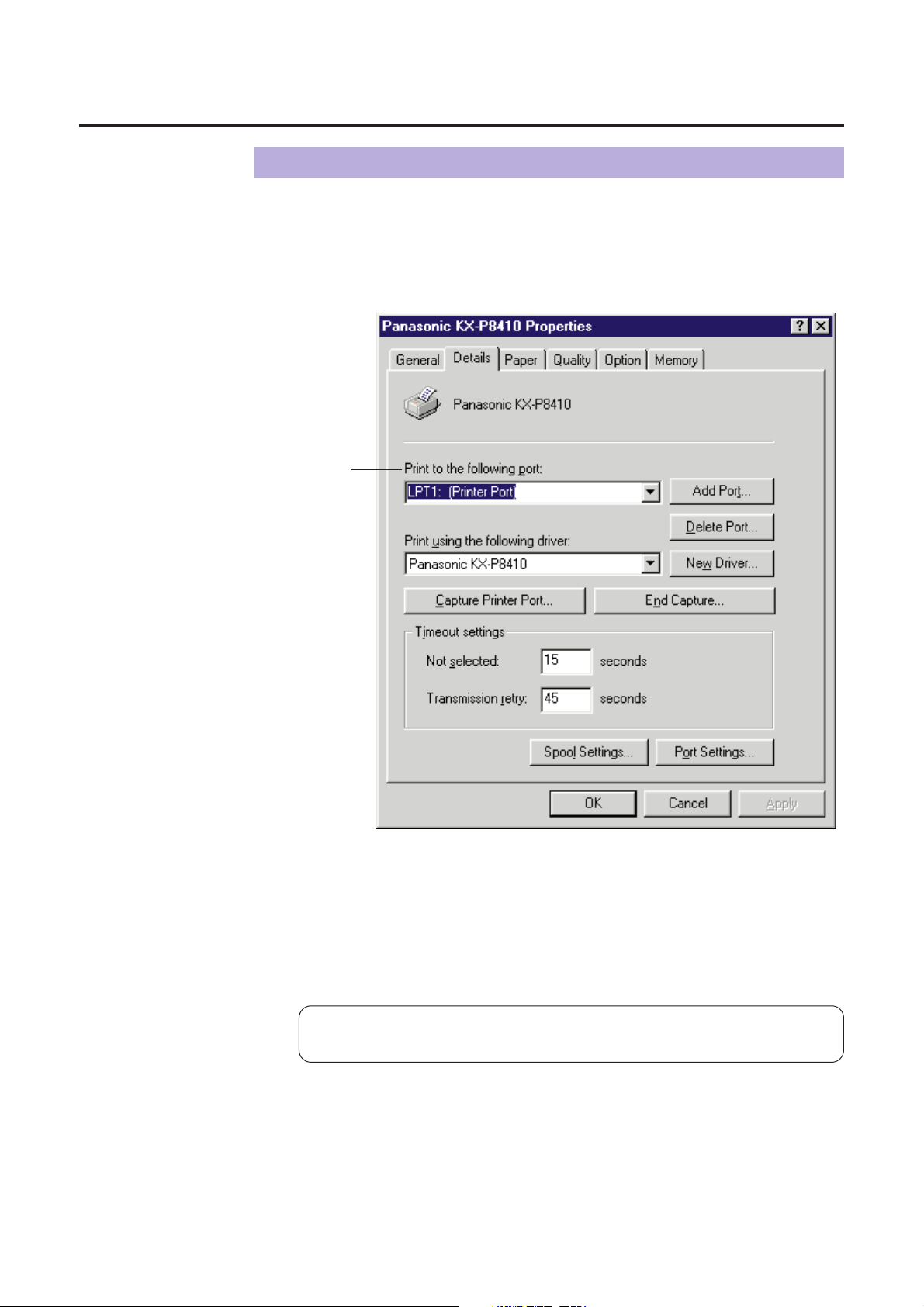
Details Tab
#
Print to the following port
Select the port where the parallel interface cable is connected.
When you are using the SCSI interface cable, select the KX-P8410GDI
(KX-P8410 on SCSI).
#
Note:
B
This option is available only in Windows 95.
For the functions of other buttons, refer to the Help menu in the
Windows.
Page 70

70
#
Paper size
Selects a different paper size.
Letter, A4, Legal or Envelope can be selected.
$
Orientation
Selects Portrait (vertical) or Landscape (horizontal).
Portrait Landscape
%
Output order
Specifies whether the document prints face up or face down in the output
tray. This selection is not effective when the multi-purpose tray (MPT Plain
Paper, MPT Transparency, etc.) is selected in the Paper source (☞P. 71).
When the multi-purpose tray is selected, Face up is selected automatically.
Using the Printer
Paper Tab
#
$
%
&
'
)(
A A
Page 71

71
&
Paper source
Selects media by choosing the location (trays) or the type of media.
BAuto [Plain Paper]:
Prints on paper loaded in a paper tray. The printer picks paper from the
paper tray that loaded with the media size you selected in an
application software. When the tray is empty, the printer automatically
picks from another paper tray of the same media size in the order of
Upper, Middle and Lower.
BAuto [Transparency]:
Prints on transparency loaded in a transparency tray. The printer picks
transparency from the transparency tray that loaded with the media
size you selected in an application software. When the tray is empty,
the printer automatically picks from another transparency tray of the
same media size in the order of Upper, Middle and Lower.
BUpper :
Prints on media loaded in the standard tray.
BMiddleS:
Prints on media loaded in the upper tray (optional feeder).
BLowerS :
Prints on media loaded in the lower tray (optional feeder).
BMPT Plain Paper, MPT Transparency, MPT Label, MPT Coated
Paper, MPT Envelope, MPT Paper 2nd Side :
Prints on paper, transparency or label , etc. loaded in the Multi-purpose
tray. The printer will print on the selected media with optimal quality.
S
If the optional feeder has not been installed, the printer selects the
standard tray automatically.
'
Copies
Determines how many copies of the document will be printed.
Note:
BThe number of copies can be also determined using some application
softwares. However, it is recommended to set the number of copies using
one method, either from this driver or from an application software to
avoid having a printing problem.
(
About... button
Displays the window which contains the program version and copyright
information.
)
Restore Defaults button
Resets the Paper tab’s settings to the default settings.
Using the Printer
Page 72

72
Using the Printer
Quality Tab
#
$
%
&
'
# Print style
Select a type which is the closest to your document to print for optimal
quality.
BBlack Text:
Prints the document in black and white the quickest. Select this for
black and white text files.
BGray Scale:
Prints the document in black and white. Select this for monochrome
halftone images.
BColor Graphics: (default)
Prints the document in color. Select this for computer graphics, colored
text, and spreadsheets with color graphics.
Small text can be printed more clearly than when printed in
Presentation.
BColor Photo:
Prints the document in color. Select this for photo images such as a
photo from a CD.
BPresentation:
Prints the document in color. Select this for presentation printing.
Presentation provides a clearer tone than Color Graphics.
Page 73

73
Using the Printer
$ Dithering mode
Color Graphics and Color Photo are print styles that simulate shades of
color by changing the dot patterns. You can select a dot pattern using
DefaultS, Dither A or Dither B.
This selection is effective only when Color Graphics or Color Photo is
selected.
S
Most appropriate Dithering mode may be automatically selected according
to the print style, print quality and printer memory you have selected.
Notes:
BWhen Color Graphics is selected in the Print Style, Dithering mode is
available for all print quality selections.
BWhen Color Photo is selected in the Print Style, Dithering mode is available
only for 600 dpi and 1200 dpi print quality selections.
BIf the error message “Memory Overflow” appears when Default or Dither B is
selected, change the selection to Dither A. With Dither A selected, memory
overflow may not occur.
%
Print quality
Selects a print quality. Fast (300 dpi), Standard (600 dpi) or High quality
(1200 dpi) can be selected. A higher resolution provides better print quality.
However, the throughput speed is diminished.
When Presentation is selected in the Print style, print quality cannot be
selected and 300 dpi is automatically assigned.
&
About button
Displays the window that contains the program version and copyright
information.
'
Restore Defaults button
Resets the Quality tab’s settings to the default settings.
Page 74

74
Using the Printer
Option Tab
# Color management
This feature provides two-color adjustment functions as described below.
These functions are effective only when printing a document with Color
Graphics, Color Photo or Presentation print style.
BUse Hyper-Tetra Adjustment
Adjusts the brightness, contrast, hue, saturation, or red, green, blue, or
cyan, magenta, yellow, black of the image. For the adjustment, refer to
Using the Hyper-Tetra Adjustment ( ☞P. 97).
BUse image color matching (ICM)
S1
The printer assigns the best color possible to represent the original
color accurately by selecting different rendering intents (Saturation,
Contrast or Colormetric). Click on this check box, then click the
Rendering intent button. The Rendering intent window appears. Select
the desired rendering intent, which determines how the printer assigns
the color.
S1
This option is available only for Windows 95.
#
$
%
&
'
Page 75

75
Using the Printer
$ Density (for Gray Scale)
Adjusts the density of the gray scale image. This function is effective only
when the Gray Scale print style ( ☞P. 72 Quality Tab) is selected.
For the adjustment, refer to Using the Density Adjustment ( ☞P. 102).
%
Print as a mirror image
Clicking on this check box allows you to print a mirror image of the
document.
&
About button
Displays the window that contains the program version and copyright
information.
'
Restore Defaults button
Resets the Option tab’s settings to the default settings.
Page 76

76
Memory Tab
#
Printer memory
Selects the amount of memory installed in the printer. If the amount of
memory in the printer does not match this setting, a MEMORY
OVERFLOW message might be displayed. To determine how much
memory is installed in the printer, print out the Test page ( ☞P. 39).
As the printer memory increases, printing throughput improves. If the total
printer memory is set more than 32 MB, Use printer memory to make
print quality better can be selected in the Printer memory usage box.
Using the Printer
#
$
% &
Page 77

77
$
Printer memory usage
Determines how the printer memory is used, either for better print
performance or for better print quality. This selection is effective only when
the Gray Scale or the Color Photo print style is selected and the
Standard (600 dpi) is selected.
BUse printer memory to make print performance better
Sends the data to the printer with the standard level of compression to
improve throughput.
BUse printer memory to make print quality better
Sends the data to the printer with the lower level of compression or
without compression to improve the print quality. However, the
throughput will be diminished. More than 32 MB is required on the
printer to select this option.
%
About button
Displays the window that contains the program version and copyright
information.
&
Restore Defaults button
Resets the Option tab’s setting to the default setting.
Using the Printer
Page 78

78
The KX-P8410 Default Document Properties window can be displayed from Printers
under Windows ( ☞see A below) or from an application
(☞see B on page 79).
From Printers Under Windows NT 4.0
Click Start , select Settings, then click Printers.
The Printers window is displayed.
Click the
Panasonic KX-P8410
icon.
Click the File menu, then click Document Defaults....
The Panasonic KX-P8410 Default Document Properties window appears.
A
2
1
3
Using the Printer
Displaying the Panasonic KX-P8410 Default Document Properties Window (for Windows NT 4.0)
Page 79

79
Using the Printer
Click a tab to view the features.
Page Setup Tab ( ☞P. 80)
Advanced Tab (☞P. 82)
4
From an application
For example, to print a document created in Microsoft WordPad on Windows NT 4.0,
perform the following steps.
Click Start , select Programs, select Accessories, then click
WordPad.
The WordPad window is displayed.
Click the File menu, then click Print... .
The Print window is displayed.
Select Panasonic KX-P8410 in the Name : box.
Click Properties .
The Panasonic KX-P8410 Document Properties window is displayed.
Click a tab to view the features.
Page Setup Tab ( ☞P. 80)
Advanced Tab ( ☞P. 82)
Note:
B
The print options in the File menu depend upon the Windows application. Refer
to the application manual.
B
2
1
3
4
5
Page 80

80
Using the Printer
#
Paper Size
Selects a different paper size.
Letter, A4, Legal or Envelope #10 can be selected.
Page Setup Tab
#
$
%
&
Page 81

81
Using the Printer
$
Paper Source
Selects media by choosing the location (trays) or the type of media.
BAuto [Plain Paper]:
Prints on paper loaded in a paper tray. The printer picks paper from the
paper tray that is loaded with the media size you selected in the
application software. When the tray is empty, the printer automatically
picks from another paper tray of the same media size in the order of
Upper, Middle and Lower.
BAuto [Transparency]:
Prints on transparency loaded in a transparency tray. The printer picks
transparency from the transparency tray that is loaded with the media
size you selected in the application software. When the tray is empty,
the printer automatically picks from another transparency tray of the
same media size in the order of Upper, Middle and Lower.
BUpper :
Prints on media loaded in the standard tray.
BMiddleS1:
Prints on media loaded in the upper tray (optional feeder).
BLowerS1:
Prints on media loaded in the lower tray (optional feeder).
BMPT Plain Paper, MPT Transparency, MPT Label, MPT Coated
Paper, MPT Envelope, MPT Paper 2nd Side :
Prints on paper, transparency or label, etc. loaded in the Multi-purpose
tray. The printer will print on the selected media with optimal quality.
S1
If the optional feeder has not been installed, the printer selects the
standard tray automatically.
%
Copy Count
Determines how many copies of the document will be printed.
Note:
B
The number of copies can also be determined using the application
software. However, it is recommended to set the number of copies using
one method, either from this driver or from the application software to
avoid printing problems.
&
Orientation
Selects Portrait (vertical) or Landscape (horizontal).
Portrait Landscape
A
A
Page 82

82
Using the Printer
Two categories (Paper/Output and Document Options) for document settings are
available. To display the items of a category, click on that category.
■ Paper/Output
As for the features of each items (Paper Size, Orientation, Paper Source, Copy
Count), refer to Page Setup Tab ( ☞ P. 80).
Clicking on an item displays its selections in the lower box. Click your desired
selection, then click OK .
Advanced Tab
Page 83

83
■ Document Options
# Print Style
Click on Print Style to display its selections in the lower box, and
select a type which is the closest to your document to ensure optimal
print quality.
BBlack Text:
Prints the document in black and white. Select this for black and white
text. This is the fastest printing option.
BGray Scale:
Prints the document in black and white. Select this for monochrome
halftone images.
BColor Graphics: (default)
Prints the document in color. Select this for computer graphics, color
text or spreadsheets with color graphics.
(Small text can be printed more clearly than when printed in
Presentation.)
BColor Photo:
Prints the document in color. Select this for photo images such as a
photo from a CD.
BPresentation:
Prints the document in color. Select this for presentation printing.
(Presentation provides a clearer tone than Color Graphics.)
Using the Printer
#
$
%
&
(
)
'
*
Page 84

84
Using the Printer
$
Print Quality
Click on Print Quality to display its selections in the lower box, and select
a print quality. Fast (300 dpi), Standard (600 dpi) or High quality (1200
dpi) can be selected. A higher resolution provides better print quality.
However, the throughput speed is diminished.
When Presentation is selected in the Print style, print quality cannot be
selected and 300 dpi is automatically assigned.
% Dithering Mode
Color Graphics and Color Photo are print styles that simulate shades of
color by changing the dot patterns. You can select a dot pattern using
DefaultS1, Dither A, or Dither B.
This selection is effective only when Color Graphics or Color Photo is
selected.
S
1
Most appropriate Dithering mode may be automatically selected
according to the print style, print quality and printer memory you have
selected.
Notes:
BWhen Color Graphics is selected in the Print Style, Dithering mode is
available for all print quality selections.
BWhen Color Photo is selected in the Print Style, Dithering mode is available
only for 600 dpi and 1200 dpi print quality selections.
BIf the error message “Memory Overflow” appears when Default or Dither B is
selected, change the selection to Dither A. With Dither A selected, memory
overflow may not occur.
Page 85

85
Using the Printer
& Output Order
Specifies whether the document exits face up or face down into the output
tray. This selection is not effective when the multi-purpose tray (MPT Plain
Paper, MPT Transparency, etc.) is selected in the Paper Source
( ☞ P. 81). When the multi-purpose tray is selected, Face up is selected
automatically.
'
Hyper-Tetra Adjustment...
Adjusts the brightness, contrast, hue, saturation, or red, green, blue, or
cyan, magenta, yellow, black of the image. For the adjustment, refer to
Using the Hyper-Tetra Adjustment ( ☞P. 97). This function is effective
only when the Color Graphics, Color Photo or Presentation print style is
selected.
(
Gray Scale Density Adjustment...
Adjusts the density of the gray scale image. This function is effective only
when the Gray Scale print style ( ☞P. 83 Advanced Tab) is selected.
For the adjustment, refer to Using the Density Adjustment ( ☞P. 102).
)
Print as a Mirror image
Clicking on Print as a Mirror image allows you to print a mirror image of
the document.
*
Metafile Spooling
Specifies the format in which the printing information is stored on your disk
for printing. Generally, metafile spooling set to Enabled frees up your
program faster than Disabled.
Page 86

86
Using the Printer
■ When Panasonic KX-P8410 Document Settings is
selected
#
Undo Changed Option
Returns the Page Setup and Advanced tab’s settings to the previous
settings.
$
About KX-P8410 Printer Driver...
Displays the window that contains the program version and copyright
information.
#
$
Page 87

87
Using the Printer
Click Start , select Settings, then click Printers.
The Printers window is displayed.
Click the
Panasonic KX-P8410
icon.
Click the File menu, then click Properties.
The Panasonic KX-P8410 Properties window is displayed.
Displaying the Panasonic KX-P8410 Properties Window (for Windows NT 4.0)
2
1
3
Click a tab to view the features.
Ports Tab ( ☞P. 88)
Sharing Tab ( ☞P. 92)
Device Settings Tab ( ☞P. 95)
4
For the features of the other tabs, refer to the Help menu in the
Windows NT 4.0.
Page 88

88
Using the Printer
#
Checked port
Documents will print to the checked port.
$
Add Port... button
Adds a new port ( ☞P. 89 Installing the SCSI port).
Ports Tab (SCSI port)
Note:
BThis option is available only for Windows NT 4.0.
#
$
Page 89

Click Add Port... .
The Printer Ports window appears.
89
Using the Printer
■ Installing the SCSI port
Notes:
B
It is recommended that you do not connect the printer directly to the file server.
Otherwise the printer and server performance may be diminished.
B
When printing through the SCSI port, the access speed between other
connected SCSI devices get slower.
B
To connect the KX-P8410 to your SCSI port, a SCSI driver and ASPI Manager
need to be installed. Refer to your SCSI board manual.
1
Click New Monitor... .
The Installing Print Monitor window appears.
2
Page 90

90
Using the Printer
Insert the KX-P8410 CD-ROM into the CD-ROM drive.
Click Browse... .
Click Cancel .
The Locate File window is displayed.
Note:
B
The SCSI port cannot be installed through the Monitor.inf file when copied to a
directory with long file name.
Select CD-ROM drive.
Open Winnt40, Disk2, then select Monitor.inf file.
Click Open .
Click OK .
The Printer Ports window is displayed.
3
4
5
6
7
8
Page 91

91
Using the Printer
Click New Port... .
The Port Name window is displayed.
Type the port name (for example; KXP8410GDI), then click
OK .
The Printer Ports window is displayed.
Click Close .
9
10
11
Page 92

92
Using the Printer
#
Shared
To share the printer over the network.
For the setup operation, refer to Sharing the printer with a client
computer ( ☞P. 93).
$
Alternate Drivers
To install an alternate driver.
For the installation, refer to Installing an alternate driver ( ☞P. 93).
Sharing Tab
#
$
Page 93

93
Using the Printer
■ Sharing the printer with a client computer
Click Shared.
Type the printer name (for example: KX-P8410).
Note:
B
If the shared printer is used through Windows 95, the printer name must not
exceed 12 characters.
Click OK .
■ I
nstalling an alternate driver (for example: Windows 95)
Select Windows 95, then click OK .
The Insert Disk window is displayed.
Click OK .
The Printer Drivers for Windows 95 window is displayed.
Click Browse... .
1
2
3
1
2
3
Page 94

94
Using the Printer
Click Cancel .
The Locate File window is displayed.
Insert the supplied KX-P8410 CD-ROM into the CD-ROM drive.
Select CD-ROM drive.
Open Win95, Disk2, then select KXP8410.inf file. Click Open .
The Printer Drivers for Window 95 window is displayed.
Click OK .
6
7
8
4
5
Page 95

95
Using the Printer
Device Settings Tab
#
Printer memory
Selects the amount of memory installed in the printer. If the amount of
memory in the printer does not match this setting, a MEMORY
OVERFLOW message might be displayed. To determine how much
memory is installed in the printer, print out the Test page ( ☞P. 39).
As the printer memory increases, printing throughput improves. If the total
printer memory is set more than 32 MB, Printer memory usage option ($)
becomes effective.
#
$
%
Page 96

96
Using the Printer
$
Printer memory usage
Determines how the printer memory is used, either for better print
performance or for better print quality. This selection is effective only when
the Gray Scale or the Color Photo print style is selected and the
Standard (600 dpi) is selected.
More than 32 MB is required on the printer to select this option.
BUse printer memory to make print performance better
Sends the data to the printer with the standard level of compression to
improve throughput.
BUse printer memory to make print quality better
Sends the data to the printer with a lower level of compression or
without compression to improve the print quality. However, the
throughput will be diminished.
%
Form To Tray Assignment
Server can assign and display the media loaded in the printer. Client can
view the media assignment. This assignment does not affect any print job.
■ When Panasonic KX-P8410 Device Settings is
selected
#
Undo Changed Option
Returns the Device Settings tab’s setting to the previous setting.
$
About KX-P8410 Printer Driver...
Displays the window that contains the program version and copyright
information.
#
$
Page 97

97
Using the Printer
You can adjust the color of your output using the Hyper-Tetra Adjustment window.
Displaying the Hyper-Tetra Adjustment Window
Using the Hyper-Tetra Adjustment
■For Windows 95 / 3.1
Click on the Use Hyper-Tetra Adjustment check box in the
Option tab
( ☞P. 74)
.
The Adjustment... button becomes effective.
Click Adjustment... .
The Hyper-Tetra Adjustment window is displayed.
■For Windows NT 4.0
Click on Hyper-Tetra Adjustment ... in the Advanced tab
( ☞ P. 82).
The Hyper-Tetra Adjustment... button appears in the lower box.
Click Hyper-Tetra Adjustment... .
The Hyper-Tetra Adjustment window is displayed.
1
2
1
2
Page 98

98
To adjust the brightness, contrast, hue or saturation of color, select Color
Adjustment in the
Hyper-Tetra Adjustment window
.
#
Brightness
Changes the brightness of an image. A higher brightness setting provides a
lighter image and a lower brightness setting provides a darker image.
$
Contrast
Adjusts the range between the darkest and the lightest shades in the
image.
%
Hue
Changes the aspect of color.
&
Saturation
Changes the brightness and vividness of color. Lower saturation settings
provide dull and dark images, and higher saturation settings provide bright
and vivid images.
The range of each option (#to &) is from 0 to 255.
'
OK button
Makes a selection effective and closes the window.
(
Cancel button
Cancels a selection and closes the window.
Using the Printer
Color Adjustment
#
$
%
&
' () *
Preview box
Page 99

99
)
About button
Displays the window that contains the program version and copyright
information.
*
Reset button
Resets the current setting(s) made in this window to the default setting(s).
Adjust the color by performing the following steps.
Drag each slider left or right or click Ior H, or type the
numerical value.
B
You can see the result of the adjustment in the Preview box.
B
To reset the setting, click Reset .
Click OK to make the setting(s) effective.
1
2
Using the Printer
Page 100

100
To adjust the level of red, green or blue, select Color Balance in the Hyper-Tetra
Adjustment window. The following options appear.
#
Red
Lightens or darkens red. A darker level setting provides a stronger cyan.
$
Green
Lightens or darkens green. A darker level setting provides a stronger
magenta.
%
Blue
Lightens or darkens blue. A darker level setting provides a stronger yellow.
The setting range of each option is from 0 to 255.
Color Balance
Using the Printer
#
$
%
Preview box
Adjust the color by performing the following steps.
Drag each slider left or right or click Ior H, or type the
numerical value.
B
You can see the result of the adjustment in the Preview box.
B
To reset the settings, click Reset .
Click OK to make the setting(s) effective.
Darker
1
2
Lighter
 Loading...