


Nortel Secure Router 8000 Series
Troubleshooting - VAS
Release:
Document Revision:
www.nortel.com
5.3
01.01
NN46240-709 324767-A

Nortel Secure Router 8000 Series
Release: 5.3
Publication: NN46240-709
Document status: Standard
Document release date: 30 March 2009
Copyright © 2009 Nortel Networks
All Rights Reserved.
Printed in Canada, India, and the United States of America
LEGAL NOTICE
While the information in this document is believed to be accurate and reliable, except as otherwise expressly
agreed to in writing NORTEL PROVIDES THIS DOCUMENT "AS IS" WITHOUT WARRANTY OR CONDITION OF
ANY KIND, EITHER EXPRESS OR IMPLIED. The information and/or products described in this document are
subject to change without notice.
Nortel, the Nortel logo, and the Globemark are trademarks of Nortel Networks.
All other trademarks are the property of their respective owners.
ATTENTION
For information about the safety precautions, read "Safety messages" in this guide.
For information about the software license, read "Software license" in this guide.

Nortel Secure Router 8000 Series
Troubleshooting - VAS Contents
Contents
About this document.......................................................................................................................1
1 AAA troubleshooting................................................................................................................1-1
1.1 AAA overview .............................................................................................................................................1-2
1.1.1 AAA, RADIUS, and HWTACACS...................................................................................................1-2
1.1.2 Domains and address pool.................................................................................................................1-4
1.1.3 Schemes and modes ..........................................................................................................................1-5
1.1.4 Server templates................................................................................................................................1-6
1.2 Troubleshooting local user authentication...................................................................................................1-6
1.2.1 Typical networking............................................................................................................................1-6
1.2.2 Configuration notes...........................................................................................................................1-7
1.2.3 Troubleshooting flowchart ................................................................................................................1-9
1.2.4 Troubleshooting procedure................................................................................................................1-9
1.3 Troubleshooting RADIUS authentication..................................................................................................1-10
1.3.1 Typical networking.......................................................................................................................... 1-11
1.3.2 Configuration notes.........................................................................................................................1-11
1.3.3 Troubleshooting flowchart ..............................................................................................................1-14
1.3.4 Troubleshooting procedure..............................................................................................................1-15
1.4 Troubleshooting HWTACAS authentication ............................................................................................. 1-17
1.4.1 Typical networking..........................................................................................................................1-17
1.4.2 Configuration notes.........................................................................................................................1-17
1.4.3 Troubleshooting flowchart ..............................................................................................................1-21
1.4.4 Troubleshooting procedure..............................................................................................................1-22
1.5 Troubleshooting cases ...............................................................................................................................1-23
1.5.1 FTP user fails to pass through RADIUS authentication ..................................................................1-23
1.5.2 HWTACACS user fails to get the delivered address.......................................................................1-25
1.6 FAQs..........................................................................................................................................................1-26
1.7 Diagnostic tools.........................................................................................................................................1-30
1.7.1 Display commands..........................................................................................................................1-30
1.7.2 Debugging commands.....................................................................................................................1-32
2 IPSec and IKE troubleshooting ...............................................................................................2-1
2.1 IPSec and IKE overview .............................................................................................................................2-3
Issue 01.01 (30 March 2009)
Nortel Networks Inc.
i

Contents
Nortel Secure Router 8000 Series
Troubleshooting - VAS
2.2 Troubleshooting manual IPSec SA setup.....................................................................................................2-6
2.2.1 Typical networking............................................................................................................................2-6
2.2.2 Configuration notes...........................................................................................................................2-6
2.2.3 Troubleshooting flowchart ..............................................................................................................2-11
2.2.4 Troubleshooting procedure..............................................................................................................2-12
2.3 Troubleshooting ISAKMP SA ...................................................................................................................2-14
2.3.1 Typical networking..........................................................................................................................2-14
2.3.2 Configuration notes.........................................................................................................................2-15
2.3.3 Troubleshooting flowchart ..............................................................................................................2-19
2.3.4 Troubleshooting procedure..............................................................................................................2-21
2.4 Troubleshooting SA setup using an IPSec policy template .......................................................................2-24
2.4.1 Typical networking..........................................................................................................................2-24
2.4.2 Configuration notes.........................................................................................................................2-25
2.4.3 Troubleshooting flowchart ..............................................................................................................2-30
2.4.4 Troubleshooting procedure..............................................................................................................2-31
2.5 Troubleshooting NAT traversal in the IPSec tunnel ..................................................................................2-32
2.5.1 Typical networking..........................................................................................................................2-33
2.5.2 Configuration notes.........................................................................................................................2-33
2.5.3 Troubleshooting flowchart ..............................................................................................................2-40
2.5.4 Troubleshooting procedure..............................................................................................................2-41
2.6 Troubleshooting GRE over IPSec or L2TP over IPSec............................................................................. 2-42
2.6.1 Typical networking..........................................................................................................................2-42
2.6.2 Configuration notes.........................................................................................................................2-43
2.6.3 Troubleshooting flowchart ..............................................................................................................2-46
2.6.4 Troubleshooting procedure..............................................................................................................2-47
2.7 Troubleshooting cases ...............................................................................................................................2-48
2.8 FAQs..........................................................................................................................................................2-49
2.9 Diagnostic tools.........................................................................................................................................2-50
2.9.1 Display commands..........................................................................................................................2-50
2.9.2 Debugging commands.....................................................................................................................2-59
3 Firewall troubleshooting ..........................................................................................................3-1
3.1 Firewall........................................................................................................................................................3-2
3.2 Troubleshooting the firewall........................................................................................................................3-2
3.2.1 Networking environment...................................................................................................................3-3
3.2.2 Configuration notes...........................................................................................................................3-3
3.2.3 Diagnostic flowchart .........................................................................................................................3-3
3.2.4 Troubleshooting procedures..............................................................................................................3-5
3.3 FAQs............................................................................................................................................................3-6
3.4 Diagnostic tools...........................................................................................................................................3-6
4 NAT troubleshooting ................................................................................................................4-1
4.1 NAT .............................................................................................................................................................4-2
ii
Nortel Networks Inc.
Issue 01.01 (30 March 2009)

Nortel Secure Router 8000 Series
Troubleshooting - VAS Contents
4.1.1 NAT attributes ...................................................................................................................................4-2
4.1.2 NAT modes........................................................................................................................................4-3
4.1.3 Special protocols supported by the address translation.....................................................................4-3
4.2 Troubleshooting NAT Troubleshooting.......................................................................................................4-4
4.2.1 Typical Networking...........................................................................................................................4-4
4.2.2 Configuration notes...........................................................................................................................4-5
4.2.3 Troubleshooting flowchart ................................................................................................................4-6
4.2.4 Troubleshooting procedures..............................................................................................................4-8
4.3 Troubleshooting cases .................................................................................................................................4-9
4.3.1 Internal Network Cannot Successfully Ping the External Network After NAT Is Configured on the
Router......................................................................................................................................................... 4-9
4.4 FAQs..........................................................................................................................................................4-10
4.5 Diagnostic tools.........................................................................................................................................4-11
4.5.1 Display commands.......................................................................................................................... 4-11
4.5.2 Debugging commands.....................................................................................................................4-19
Index ................................................................................................................................................ i-1
Issue 01.01 (30 March 2009)
Nortel Networks Inc.
iii


Nortel Secure Router 8000 Series
Troubleshooting - VAS Figures
Figures
Figure 1-1 RADIUS message structure ............................................................................................................1-2
Figure 1-2 Attribute format...............................................................................................................................1-3
Figure 1-3 Networking diagram of local authentication...................................................................................1-7
Figure 1-4 Troubleshooting flowchart of local user authentication ..................................................................1-9
Figure 1-5 Networking diagram of RADIUS authentication.......................................................................... 1-11
Figure 1-6 Troubleshooting flowchart of RADIUS authentication.................................................................1-14
Figure 1-7 Networking diagram of HWTACAS authentication .....................................................................1-17
Figure 1-8 Troubleshooting flowchart of HWTACACS authentication .........................................................1-21
Figure 1-9 Networking diagram of RADIUS authentication..........................................................................1-23
Figure 1-10 Networking diagram of HWTACAS authentication ...................................................................1-25
Figure 2-1 Format of the transport mode packets.............................................................................................2-4
Figure 2-2 Format of the tunnel mode packets.................................................................................................2-4
Figure 2-3 Networking diagram of the manual IPSec SA setup .......................................................................2-6
Figure 2-4 Troubleshooting flowchart of IPSec SA manual setup..................................................................2-11
Figure 2-5 Networking diagram of setting up ISAKMP IPSec ......................................................................2-15
Figure 2-6 Troubleshooting flowchart of SA setup in Phase 1 .......................................................................2-20
Figure 2-7 Troubleshooting flowchart of SA setup in Phase 2 .......................................................................2-21
Figure 2-8 Networking diagram of setting up SA using an IPSec policy template.........................................2-25
Figure 2-9 Troubleshooting flowchart of setting up IPSec SA using an IPSec policy template .....................2-30
Figure 2-10 Networking diagram of IPSec NAT ............................................................................................2-33
Figure 2-11 Troubleshooting flowchart of NAT traversal in IPSec ................................................................2-40
Figure 2-12 Networking diagram of configuring IPSec .................................................................................2-43
Figure 2-13 Troubleshooting flowchart of GRE over IPSec...........................................................................2-46
Figure 2-14 Networking diagram of IPSec setup ...........................................................................................2-48
Figure 3-1 Networking of the firewall..............................................................................................................3-3
Figure 3-2 Diagnostic flowchart for faults on the firewall ...............................................................................3-4
Issue 01.01 (30 March 2009)
Nortel Networks Inc.
v

Figures
Nortel Secure Router 8000 Series
Troubleshooting - VAS
Figure 4-1 NAT principles................................................................................................................................4-2
Figure 4-2 NAPT working mode......................................................................................................................4-3
Figure 4-3 NAT networking..............................................................................................................................4-4
Figure 4-4 Networking of the load balancing, flow control and BT speed control on the NAT server ............4-5
Figure 4-5 troubleshooting flowchart...............................................................................................................4-7
Figure 4-6 Internal network fails to ping the external network ........................................................................4-9
vi
Nortel Networks Inc.
Issue 01.01 (30 March 2009)

Nortel Secure Router 8000 Series
Troubleshooting - VAS Contents
Contents
About this document....................................................................................................................... 1
Issue 01.01 (30 March 2009)
Nortel Networks Inc.
i


Nortel Secure Router 8000 Series
Troubleshooting - VAS About this document
About this document
Overview
This section describes the organization of this document, product version, intended audience,
conventions, and update history.
Related versions
The following table lists the product versions related to this document.
Product Name Version
Nortel Secure Router 8000 Series V200R005
Intended audience
This document is intended for the following audience:
z
network operators
z
network administrators
z
network maintenance engineers
Organization
This document consists of three chapters related to Value Added Service (VAS)
troubleshooting and is organized as follows.
Chapter Description
1 AAA troubleshooting This chapter describes the troubleshooting procedure for the
Issue 01.01 (30 March 2009)
Authentication, Authorization, and Accounting (AAA)
protocol; frequently asked questions (FAQ); and diagnostic
tools.
Nortel Networks Inc.
1
About this document
Nortel Secure Router 8000 Series
Troubleshooting - VAS
Chapter Description
2 IPSec and IKE
troubleshooting
3 Firewall
Troubleshooting
4 NAT troubleshooting This chapter describes the troubleshooting procedure for
Conventions
This section describes the symbol and text conventions used in this document
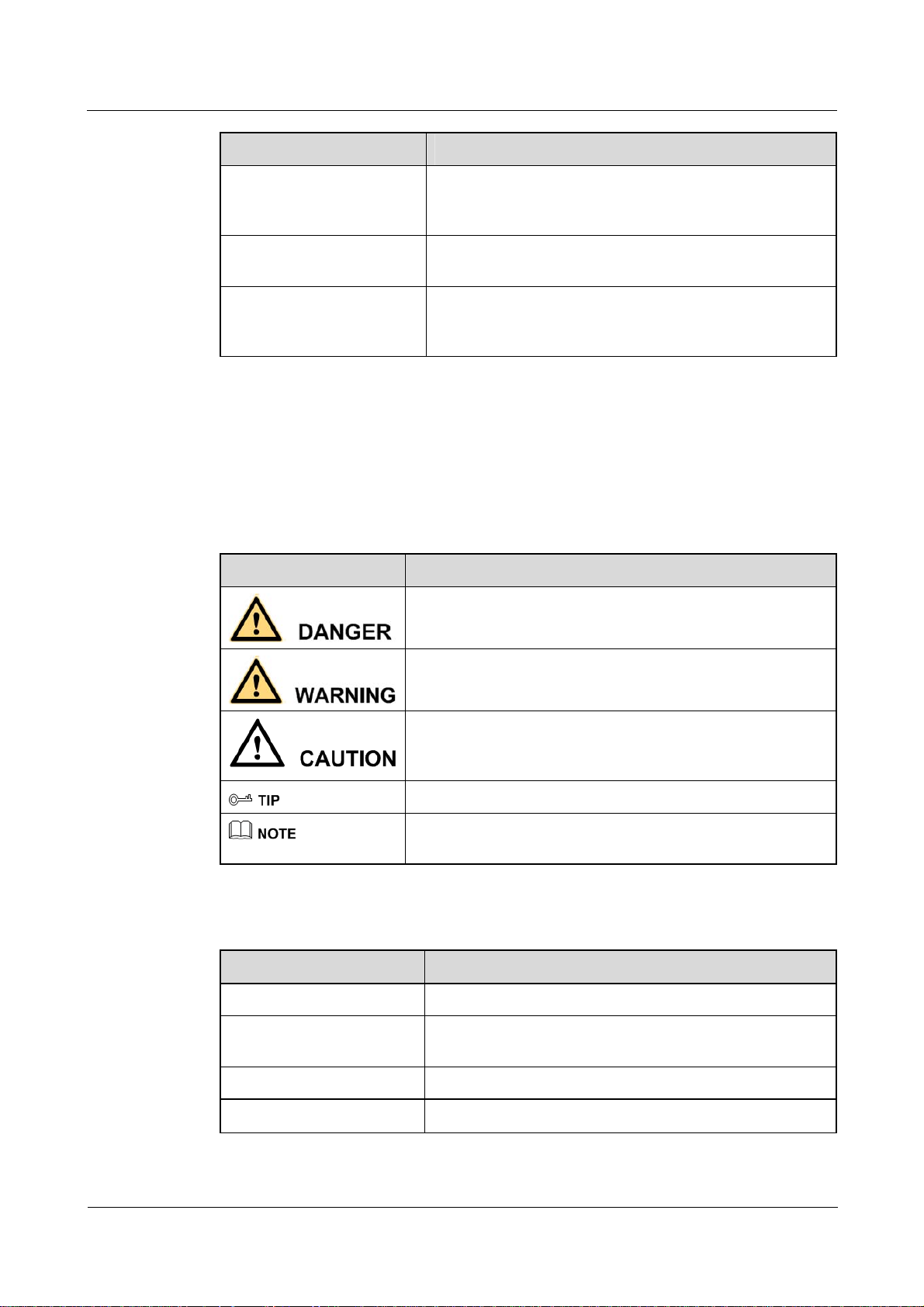
Symbol conventions
Symbol Description
This chapter describes troubleshooting procedures for IP
Security (IPSec) and Internet Key Exchange (IKE), FAQs,
and diagnostic tools.
This chapter describes the troubleshooting procedure for
Firewall, FAQs, and diagnostic tools.
Network Address Translation (NAT), FAQs, and diagnostic
tools.
Indicates a hazard with a high level of risk that, if not avoided,
can result in death or serious injury.
General conventions
Convention Description
Times New Roman Normal paragraphs are in Times New Roman font.
Boldface
Italic Book titles are in italics.
Courier New
Indicates a hazard with a medium or low level of risk that, if
not avoided, can result in minor or moderate injury.
Indicates a potentially hazardous situation that, if not avoided,
can cause equipment damage, data loss, and performance
degradation, or unexpected results.
Indicates a tip that may help you solve a problem or save time.
Provides additional information to emphasize or supplement
important points of the main text.
Names of files, directories, folders, and users are in
boldface. For example, log on as the user root.
Terminal display is in Courier New font.
2
Nortel Networks Inc.
Issue 01.01 (30 March 2009)
Nortel Secure Router 8000 Series
Troubleshooting - VAS About this document
Command conventions
Convention Description
Boldface
Italic Command arguments are in italics.
[ ] Items (keywords or arguments) in square brackets [ ] are
{ x | y | ... } Alternative items are grouped in braces and separated by
[ x | y | ... ] Optional alternative items are grouped in square brackets
{ x | y | ... } * Alternative items are grouped in braces and separated by
[ x | y | ... ] *
&<1-n> The parameter before the ampersand sign (&) can be
# A line starting with the number sign (#) contains comments.
The keywords of a command line are in boldface.
optional.
vertical bars. You can select one item.
and separated by vertical bars. You can select one item or
no item.
vertical bars. You can select a minimum of one item or a
maximum of all items.
Optional alternative items are grouped in square brackets
and separated by vertical bars. You can select no item or
multiple items.
repeated 1 to n times.
GUI conventions
Convention Description
Boldface
> Multilevel menus are in boldface and separated by the
Keyboard operation
Format Description
Key
Key 1+Key 2
Key 1, Key 2 Press the keys in sequence. For example, Alt, A means
Buttons, menus, parameters, tabs, windows, and dialog box
titles are in boldface. For example, click OK.
right-angled bracket sign (>). For example, choose File >
Create > Folder.
Press the key. For example, press Enter and press Tab.
Press the keys concurrently. For example, Ctrl+Alt+A
means press the three keys concurrently.
press the two keys in sequence.
Issue 01.01 (30 March 2009)
Nortel Networks Inc.
3

About this document
Mouse operation
Action Description
Click Select and release the primary mouse button without
Double-click Press the primary mouse button twice quickly without
Drag Press and hold the primary mouse button and move the
Update history
Updates between document versions are cumulative. Therefore, the latest document version
contains all updates made to previous versions.
Nortel Secure Router 8000 Series
Troubleshooting - VAS
moving the pointer.
moving the pointer.
pointer to a new position.
Updates in Issue 1.0 ( 6 June 2008 )
This is the first commercial release of this document.
4
Nortel Networks Inc.
Issue 01.01 (30 March 2009)

Nortel Secure Router 8000 Series
Troubleshooting - VAS Contents
Contents
1 AAA troubleshooting................................................................................................................1-1
1.1 AAA overview...............................................................................................................................................1-1
1.1.1 AAA, RADIUS, and HWTACACS......................................................................................................1-2
1.1.2 Domains and address pool ...................................................................................................................1-4
1.1.3 Schemes and modes.............................................................................................................................1-4
1.1.4 Server templates...................................................................................................................................1-5
1.2 Troubleshooting local user authentication.....................................................................................................1-6
1.2.1 Typical networking ..............................................................................................................................1-6
1.2.2 Configuration notes..............................................................................................................................1-7
1.2.3 Troubleshooting flowchart...................................................................................................................1-9
1.3 Troubleshooting RADIUS authentication ...................................................................................................1-10
1.3.1 Typical networking ............................................................................................................................1-11
1.3.2 Configuration notes............................................................................................................................1-11
1.3.3 Troubleshooting flowchart.................................................................................................................1-14
1.3.4 Troubleshooting procedure ................................................................................................................1-15
1.4 Troubleshooting cases.................................................................................................................................1-17
1.4.1 FTP user fails to pass through RADIUS authentication.....................................................................1-17
1.4.2 HWTACACS user fails to get the delivered address......................................................................... 1-17
1.5 FAQs ...........................................................................................................................................................1-19
1.6 Diagnostic tools...........................................................................................................................................1-22
1.6.1 Display commands.............................................................................................................................1-22
1.6.2 Debugging commands........................................................................................................................1-25
Issue 01.01 (30 March 2009) Nortel Networks Inc. i


Nortel Secure Router 8000 Series
Troubleshooting - VAS Figures
Figures
Figure 1-1 RADIUS message structure..............................................................................................................1-2
Figure 1-2 Attribute format ................................................................................................................................1-3
Figure 1-3 Networking diagram of local authentication.....................................................................................1-6
Figure 1-4 Troubleshooting flowchart of local user authentication....................................................................1-9
Figure 1-5 Networking diagram of RADIUS authentication............................................................................1-11
Figure 1-6 Troubleshooting flowchart of RADIUS authentication ..................................................................1-14
Figure 1-7 Networking diagram of HWTACAS authentication ...................................................................... 1-15
Figure 1-8 Troubleshooting flowchart of HWTACACS authentication .......................................................... 1-16
Figure 1-9 Networking diagram of RADIUS authentication............................................................................1-17
Figure 1-10 Networking diagram of HWTACAS authentication .....................................................................1-19
Issue 01.01 (30 March 2009) Nortel Networks Inc. iii


Nortel Secure Router 8000 Series
Troubleshooting - VAS 1 AAA troubleshooting
1 AAA troubleshooting
About this chapter
The following table shows the contents of this chapter.
Section Description
1.1 AAA overview This section describes the concepts you need to know
before troubleshooting Authentication, Authorization, and
Accounting (AAA).
1.2 Troubleshooting local user
authentication
1.3 Troubleshooting RADIUS
authentication
1.4 Troubleshooting cases This section presents several troubleshooting cases.
1.5 FAQs This section lists frequently asked questions (FAQs) and
1.6 Diagnostic tools This section describes common diagnostic tools: display
This section contains configuration notes for local user
authentication, and provides the local user authentication
troubleshooting flowchart and procedure for a typical
local user authentication network.
This section contains configuration notes for RADIUS
authentication, and provides the RADIUS authentication
troubleshooting flowchart and procedure for a typical
RADIUS authentication network.
their answers.
commands and debugging commands.
1.1 AAA overview
This section describes the basic concepts of AAA, RADIUS, and HWTACACS.
Issue 01.01 (30 March 2009) Nortel Networks Inc. 1-1
1 AAA troubleshooting
1.1.1 AAA and RADIUS
AAA
Authentication, Authorization, and Accounting (AAA) contains the following three types of
security services.
z
Authentication: specifies what type of user can access the network.
z
Authorization: specifies what type of service the user can use.
z
Accounting: records the network resource utilization of the user.
AAA adopts the client/server model, in which the client runs on the resource side and the
server stores information about the user. This model is extensible and provides an effective
way to manage users.
The two communication protocols used between the client and the server are as follows:
z
Remote Authentication Dial-In User Service (RADIUS) protocol
z
Huawei Terminal Access Controller Access Control System (HWTACACS) protocol
(HWTACACS is an enhancement of TACACS)
Nortel Secure Router 8000 Series
Troubleshooting - VAS
RADIUS
RADIUS is used for communication between the Network Access Server (NAS) and the
RADIUS server on the application layer.
RADIUS adopts the client/server model in which the client runs on the resource side and the
server stores information about the user.
To ensure reliability, RADIUS supports User Datagram Protocol (UDP) packets and a
retransmission and backup server mechanism. The authentication and accounting ports used
by RADIUS are 1645/1646 or 1812/1813.
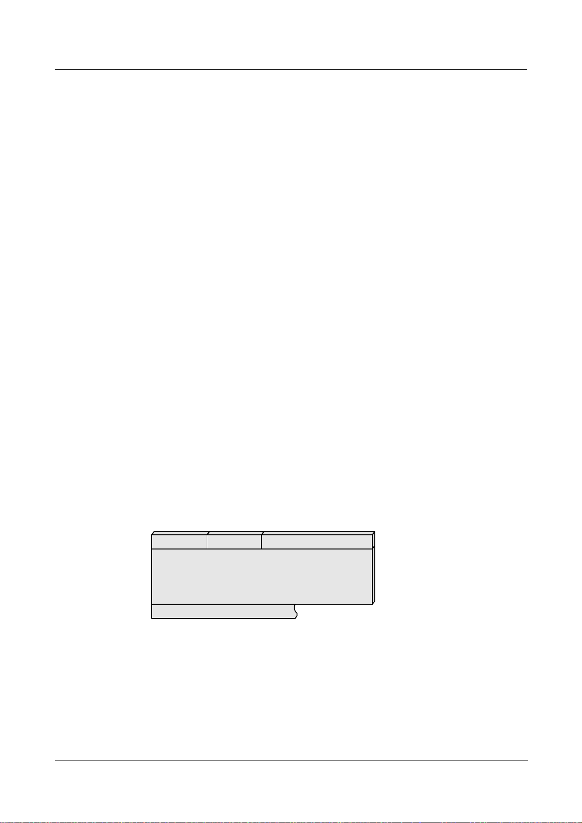
Figure 1-1 shows the RADIUS packet format.
Figure 1-1 RADIUS message structure
01234567012345670123456701234567
1
Cod e Identi fier Length
2
3
4
5
6
Attribute......
Authenticator
The following list describes the RADIUS message structure:
z
Code—contains 1 byte, indicating the RADIUS message type. The common code values
are as follows.
1-2 Nortel Networks Inc. Issue 01.01 (30 March 2009)
Nortel Secure Router 8000 Series
Troubleshooting - VAS 1 AAA troubleshooting
Value Packet type Indication Description
1 Access-request Sending an
authentication request
2 Access-accept Accepting the
authentication request
NAS sends an authentication
request to a RADIUS server.
A RADIUS server sends a
response packet to accept the
authentication request.
3 Access-request Rejecting the
authentication request
A RADIUS server sends a
response packet to reject the
authentication request.
4 Accounting-request Sending an
accounting request
5 Accounting-response Responding to the
accounting request
NAS sends an accounting
request to a RADIUS server.
A RADIUS server responds to
an accounting request packet.
The three types of accounting packets are as follows. They are distinguished by the No.40 attributes
area.
z
value of No.40 attributes area is 1: accounting start packets
z
value of No.40 attributes area is 2: hot billing packets
z
value of No.40 attributes area is 3: accounting stop packets
z
Identifier—contains 1 byte, used to match request packets or response packets.
z
Length—contains 2 bytes, indicating the total length of all fields.
z
Authenticator—contains 16 bytes. This value is used to authenticate the reply from the
RADIUS server, and is used in the password hiding algorithm.
z
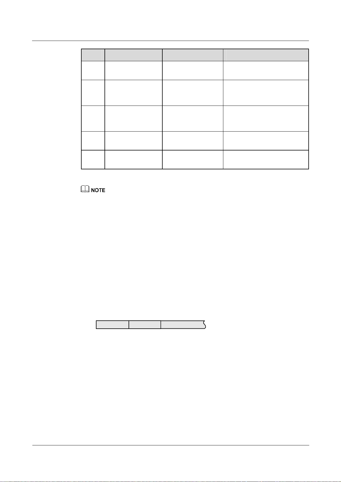
Attribute—has a flexible length and consists of various attributes. Figure 1-2 shows the
attribute format.
Figure 1-2 Attribute format
01234567012345670123456701234567
Type Length Value
− Type—indicates the attribute type.
− Length—indicates the length of every attribute and contains 1 byte.
− Value—indicates the attribute value and is flexible.
The NAS works as the RADIUS client and supports the following:
− standard RADIUS protocol and extended attributes, including RFC2865 and
RFC2866
− Nortel extended RADIUS+1.1 protocol
− active detection on the RADIUS server state
Issue 01.01 (30 March 2009) Nortel Networks Inc. 1-3

1 AAA troubleshooting
After receiving an AAA authentication or accounting message, the NAS enables
server detection if the status of the server is Down. It then transforms the message
into a packet and sends the packet to the current server. The NAS regards the server
as normal only after receiving a response packet from the current server.
− local buffer retransmission of Accounting Stop packets
If the number of retransmission events exceeds the value configured, packets are
saved to the buffer queue. The system timer periodically scans the queue, extracts the
packets, sends them to the specific server, and enables the waiting timer. If the
transmission fails or no response packet is received from the server within the
timeout period, the packet is again put back into the buffer queue.
− autoswitch of the RADIUS server
If the waiting timer expires and the current server is Down or the number of
retransmission events exceeds the maximum, another server in the server group
assumes the role of the current server to transmit packets.
1.1.2 Domains and address pool
Domains
Nortel Secure Router 8000 Series
Troubleshooting - VAS
Address pool
Most AAA configurations are related to domains. NAS divides users into different groups
based on the character string that follows the @ symbol in user names. For example,
user0001@isp1 belongs to the domain isp1 and user0002@isp2 belongs to isp2.
If no @ symbol appears in the user name, the user belongs to the default domain.
Users in the same domain have similar attributes. Configuration in a domain view can affect
all users in the domain, and domain resources can be used by all the users in the domain.
You can configure AAA schemes in a domain view. For the default domain, AAA uses the
default schemes for the domain. You can also configure a RADIUS or HWTACACS server
template.
Point-to-Point Protocol (PPP) users can use PPP address negotiation to obtain the IP address
of the local interface from the NAS. The methods are as follows:
z
Use the remote address command in the interface view to allocate an IP address to the
peer.
z
Configure an address pool in the AAA view and then use the remote address pool
command to allocate the address from the address pool to the peer.
Allocating the address from the address pool is the more flexible approach. In addition, the
address pool can be used together with the domain. Configure a global address pool in the
AAA view and a domain address pool in the domain view. Users in the domain can use the
domain address pool preferentially.
1.1.3 Schemes and modes
Authentication schemes and modes
AAA supports four authentication modes:
z
local authentication
1-4 Nortel Networks Inc. Issue 01.01 (30 March 2009)

Nortel Secure Router 8000 Series
Troubleshooting - VAS 1 AAA troubleshooting
z
non-authentication
z
RADIUS authentication
z
HWTACACS authentication
AAA also allows a random combination of the four modes.
Configure the authentication mode in the authentication scheme view. By default, local
authentication is used. Use non-authentication mode only as a last option.
The authentication-mode radius local command uses the RADIUS authentication mode first.
If that fails, it uses the local authentication mode.
Authorization schemes and modes
AAA supports four authorization modes:
z
local authorization
z
direct authorization
z
if-authenticated authorization
z
HWTACACS authorization
AAA also allows a random combination of the four modes.
The authorization-mode hwtacacs local command indicates to use the HWTACACS
authorization mode first. When that fails, it uses the local authorization mode.
In a combination containing the direct authentication mode, direct authentication should be
last, such as authorization-mode hwtacacs local none.
By default, use the local authentication mode. RADIUS performs authentication together with
authorization. RADIUS authorization does not exist.
Accounting schemes and modes
AAA supports six accounting modes:
z
local accounting
z
non-accounting
z
RADIUS accounting
z
HWTACACS accounting
z
combination of RADIUS and local accounting
z
combination of HWTACACS and local accounting
By default, the non-accounting mode is used.
Configure the hot billing interval in the accounting scheme. By default, the interval is 5
minutes.
1.1.4 Server templates
RADIUS server template
The RADIUS server template describes details of the RADIUS server. On the RADIUS server
template, you can configure authentication and accounting servers or backup authentication
and accounting servers as required.
Issue 01.01 (30 March 2009) Nortel Networks Inc. 1-5
1 AAA troubleshooting
Configure the shared key on the RADIUS server template. The shared key should be the same
as that on the server side.
RADIUS supports a specified source address. You can configure the IP address of the
specified loopback interface as the source address of RADIUS packets. You can then send the
packets to a RADIUS server.
After configuring a RADIUS server template, associate the template name with a domain in
the corresponding domain view.
HWTACACS server template
The HWTACACS server template is different from the RADIUS server template as follows:
z
It contains an authorization server and a backup authorization server.
z
It supports packets with the source address configured directly instead of the address of
the loopback interface.
After configuring an HWTACACS template, associate the template name with a domain in
the corresponding domain view.
Nortel Secure Router 8000 Series
Troubleshooting - VAS
1.2 Troubleshooting local user authentication
This section covers the following topics:
z
Typical networking
z
Configuration notes
z
Troubleshooting flowchart
z
Troubleshooting procedure
1.2.1 Typical networking
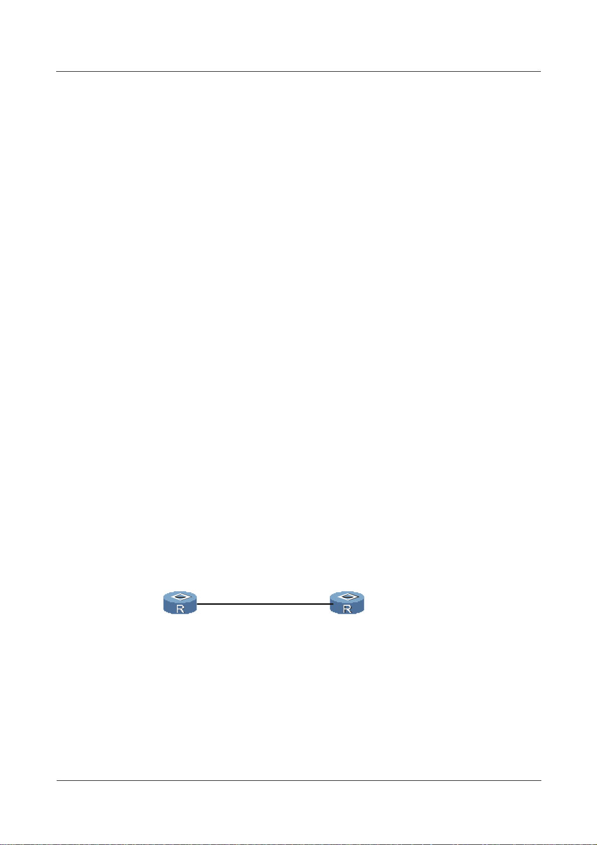
Figure 1-3 shows a typical networking diagram for local authentication.
Figure 1-3 Networking diagram of local authentication
Client
PPP Serial 4/ 0/0
9.1.1.1
Host
PPP Serial 1/ 1/0
9.1.1.2
1-6 Nortel Networks Inc. Issue 01.01 (30 March 2009)
Nortel Secure Router 8000 Series
Troubleshooting - VAS 1 AAA troubleshooting
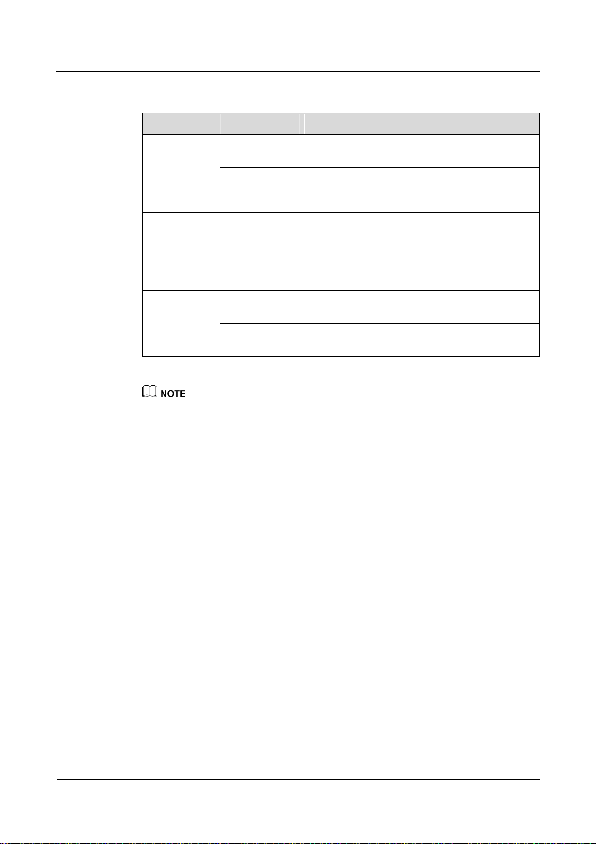
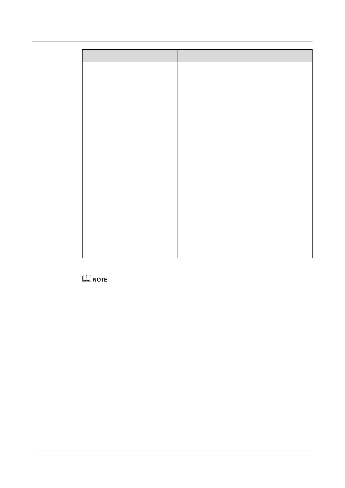
1.2.2 Configuration notes
Item Sub-item Description
Configuring
serial
interfaces on
the client side
Configuring
serial interfaces
Configure the IP
address
Configure PAP
user
authentication
Configure the IP
address
The IP address on the client side must be the same as
that on the host side.
The Password Authentication Protocol (PAP) user
name and password configured on the client side
must be consistent with those on the host side.
The IP address on the host side must be in the same
network segment as that on the client side.
on the host side
Configure PPP
authentication
The PAP user name and password configured on the
host side must be consistent with those on the client
side.
AAA on the
Configure the
domain
Configure the domain to which a PAP user belongs. Configuring
host side
Configure the
Configure the local user in the AAA view.
local user
The following sections cover part of the commands for configuring AAA, RADIUS, and HWTACACS .
For more information, see Nortel Secure Router 8000 Series Configuration Guide - Security
(NN46240-600).
Configuring the serial interface on the client side
Configure an IP address for the serial interface. In PPP/PAP mode, you need to configure the
user name and password.
<Nortel> system-view
[Nortel] interface Serial 4/0/0
[Nortel-Serial4/0/0] ip address 9.1.1.1 255.255.255.0
[Nortel-Serial4/0/0] ppp pap local-user user001@nortel password simple abc123
[Nortel-Serial4/0/0] quit
Configuring the serial interface on the host side
Configure an IP address for the serial interface and set the PPP authentication mode to PAP.
[Nortel] interface Serial 1/1/0
[Nortel-Serial1/1/0] ip address 9.1.1.2 255.255.255.0
[Nortel-Serial1/1/0] ppp authentication-mode pap
[Nortel-Serial1/1/0] quit
Configuring AAA on the host side
Configure local authentication mode.
[Nortel] aaa
[Nortel-aaa] display this
Issue 01.01 (30 March 2009) Nortel Networks Inc. 1-7

1 AAA troubleshooting
#
aaa
authentication-scheme default
#
authorization-scheme default
#
accounting-scheme default
#
domain default
#
#
Configure the local user and the domain. Configure a PAP user user001@nortel on the client
side as the local user.
[Nortel-aaa] local-user user001@nortel password simple abc123
[Nortel-aaa] domain nortel
By default, the newly configured domain is in local authentication mode, so the PAP user
user001@nortel also uses this mode. After passing through local authentication, PPP link
authentication succeeds.
Nortel Secure Router 8000 Series
Troubleshooting - VAS
1-8 Nortel Networks Inc. Issue 01.01 (30 March 2009)
Nortel Secure Router 8000 Series
Troubleshooting - VAS 1 AAA troubleshooting
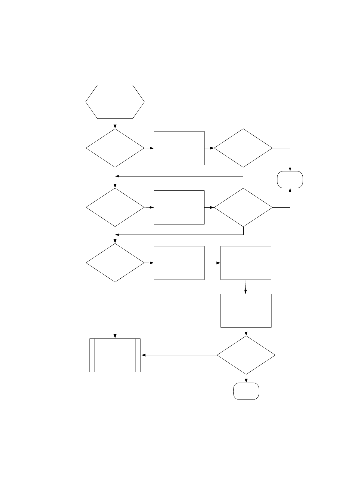
1.2.3 Troubleshooting flowchart
Figure 1-4 Troubleshooting flowchart of local user authentication
In PAP mode, the
local user
authentication fails
Ensure the PPP in
Normal PPP link?
No
up state when no
authentication mode
is configured
The fault
disappears?
Yes
Yes
Correct PAP
configuration?
Yes
Correct AAA
configuration?
Yes
No
Modify PAP
No
Is the user domain
configured?
No
The fault
disappears?
No
Is the local
authentication mode
configured?
Ensure the password
of the local user is
the same as that
used in PAP
End
Yes
Seek technical
support
No
The fault
disappears?
Yes
End
Troubleshooting procedure
Step 1 Check the PPP link.
Issue 01.01 (30 March 2009) Nortel Networks Inc. 1-9

1 AAA troubleshooting
If PAP mode is not used, check that the PPP link is Up.
# Configure the serial interface on the client side.
[Nortel] interface Serial 4/0/0
[Nortel-Serial4/0/0] ip address 9.1.1.1 255.255.255.0
[Nortel-Serial4/0/0] quit
# Configure the serial interface on the host side.
[Nortel] interface Serial 1/1/0
[Nortel-Serial1/1/0] ip address 9.1.1.2 255.255.255.0
[Nortel-Serial1/1/0] quit
In normal situations, the host can ping through 9.1.1.1. Use the display this interface
command in the interface view to view that Link Control Protocol (LCP) and IP Control
Protocol (IPCP) are “opened.” If the PPP link is Up, continue with the following steps.
Step 2 Check PAP.
Debug PAP on each interface. The following display indicates that PAP is not configured on
the peer and LCP negotiation fails.
%Sep 16 14:01:54 2005 Nortel PPP/5/NEGOTIATEFAIL:Slot=3;Serial3/0/0:0: We want to
negotiate pap , but the peer doesn't have pap configuration. So LCP negotiate fail, PPP
session will be closed.
Nortel Secure Router 8000 Series
Troubleshooting - VAS
If the PAP link is Up, continue with the following step.
Step 3 Check AAA.
Based on the preceding two steps, you can determine that a problem may exist with AAA. In
this case, check AAA as follows:
1. Use the display this command in the AAA view to check that the domain nortel exists.
2. Check if the user type is consistent with that configured in AAA. You can use the
display local-user command in the user interface view.
3. Check if the authentication scheme of the domain nortel, the default authentication
scheme, or the user-configured authentication scheme is in local authentication mode.
4. Check if user001@nortel is configured in the AAA view and the user001 password
agrees with that of the PAP user.
If the fault persists, contact Nortel technical support.
----End
1.3 Troubleshooting RADIUS authentication
This section covers the following topics:
z
Typical networking
z
Configuration notes
z
Troubleshooting flowchart
z
Troubleshooting procedure
1-10 Nortel Networks Inc. Issue 01.01 (30 March 2009)
Nortel Secure Router 8000 Series
Troubleshooting - VAS 1 AAA troubleshooting
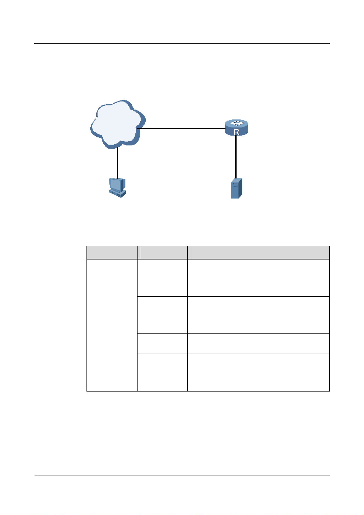
1.3.1 Typical networking
Figure 1-5 shows the networking of RADIUS authentication.
Figure 1-5 Networking diagram of RADIUS authentication
ISDN/
PSDN
Remote User
1.3.2 Configuration notes
Item Sub-item Description
Configuring the
RADIUS
server template
Configure the
authentication
server
NAS
RADIUS Server
The IP address and port of the RADIUS
authentication server are configured.
Note that the port on the template has the same
configuration as that on the RADIUS server.
Configure the
accounting
server
Configure the
shared key
Configure the
user name
format
The IP address and port for the RADIUS accounting
server are configured.
Note that the port on the template has the same
configuration as that on the RADIUS server.
The shared key of the RADIUS server template
should be the same as that on the RADIUS server.
The user name can either contain a domain name or
not contain a domain name.
In this example, the user name does not contain a
domain name.
Issue 01.01 (30 March 2009) Nortel Networks Inc. 1-11
1 AAA troubleshooting
Item Sub-item Description
Nortel Secure Router 8000 Series
Troubleshooting - VAS
Configuring
AAA
Enabling FTP
server
Configuring the
RADIUS server
Configure the
authentication
scheme
Configure the
accounting
scheme
Configure the
domain nortel
Enable the FTP
server
Configure
authentication
and accounting
ports
Configure the IP
address and
shared key for
the NAS
Configure
user001
The RADIUS authentication mode is used.
The RADIUS authentication mode is used.
A domain named nortel is created and is associated
with the authentication scheme, accounting scheme,
and RADIUS server template in the domain.
None.
For example, 1812 is the authentication port number
and 1813 is the accounting port number.
Note that the shared key of the NAS should be the
same as that on the RAIDUS server template.
In this example, the domain name is not included in
the user name. You need to configure the password
for user001. In addition, you need to configure the
delivery FTP directory on the RADIUS server.
z
The following sections cover part of the commands for configuring AAA, RADIUS, and
HWTACACS. For more information, see Nortel Secure Router 8000 Series Configuration Guide -
Security (NN46240-600).
z
RADIUS servers are configured differently, but they all support the preceding configurations.
Creating a RADIUS server template
Create a RAIDUS server template and configure the IP addresses and the port for the
authentication server and accounting server. Note the following:
z
IP addresses of RADIUS servers are routable.
z
The port configuration on the NAS should be the same as the port configuration on the
server.
z
The shared key on the NAS should be the same as the shared key on the servers.
z
In this example, the user name does not contain the domain name.
<Nortel> system-view
[Nortel] radius-server template rt_nortel
[Nortel-radius-rt_nortel] radius-server authentication 192.168.1.202 1812
[Nortel-radius-rt_nortel] radius-server accounting 192.168.1.202 1813
[Nortel-radius-rt_nortel] radius-server shared-key nortel
[Nortel-radius-rt_nortel] undo radius-server user-name domain-included
1-12 Nortel Networks Inc. Issue 01.01 (30 March 2009)

Nortel Secure Router 8000 Series
Troubleshooting - VAS 1 AAA troubleshooting
[Nortel-radius-rt_nortel] quit
Configuring AAA
z
Create a RADIUS authentication scheme and a RADIUS accounting scheme.
z
Create a domain named nortel.
z
Configure the authentication scheme, the accounting scheme, and the RADIUS server
template in the domain view.
[Nortel] aaa
[Nortel-aaa] authentication-scheme radius
[Nortel-aaa-authen-radius] authentication-mode radius
[Nortel-aaa-authen-radius] quit
[Nortel-aaa] accounting-scheme radius
[Nortel-aaa-accounting-radius] accounting-mode radius
[Nortel-aaa-accounting-radius] quit
[Nortel-aaa] domain nortel
[Nortel-aaa-domain-nortel] authentication-scheme radius
[Nortel-aaa-domain-nortel] accounting-scheme radius
[Nortel-aaa-domain-nortel] radius-server rt_nortel
[Nortel-aaa-domain-nortel] quit
[Nortel-aaa] quit
Enabling the FTP server
Enable the FTP server in the system view of the NAS.
[Nortel] ftp server enable
Info:Start FTP server
Configuring the RADIUS server
Configure the RADIUS server based on the Help files.
Configure the following items:
z
the authentication and accounting ports
z
an IP address and the shared key for the NAS
z
the user name, the password, and the authorization information
Check whether AAA takes effect on the RADIUS server by using the tool provided by the
operating system.
Issue 01.01 (30 March 2009) Nortel Networks Inc. 1-13

1 AAA troubleshooting
1.3.3 Troubleshooting flowchart
Figure 1-6 Troubleshooting flowchart of RADIUS authentication
The FTP user fails to
pass the RADIUS
authentication
Login record?
Yes
No
Can NAS transmit
the authentication
information to the
RADIUS server?
Nortel Secure Router 8000 Series
Troubleshooting - VAS
Yes
The fault disappears?
No
Failing authentication
information?
No
Can NAS
receivethe authorized
FTP directory?
Yes
Can the user
log on to the NAS
FTP server?
No
Remove the fault
No
based on the failing
authentication
information
Configure the
No
authentication mode
on the RADIUS
server correctly
Yes
Yes
The fault disappears?
No
Yes
The fault disappears?
No
End
Seek the
technical
support
1-14 Nortel Networks Inc. Issue 01.01 (30 March 2009)

Nortel Secure Router 8000 Series
Troubleshooting - VAS 1 AAA troubleshooting
1.3.4 Troubleshooting procedure
Step 1 Check that the RADIUS server displays logon records.
In a normal situation, you can view the logon records by checking the display on the server..
When the user logs on to a RAIDUS server, the server records the user name and successful
authentication. Otherwise, it records the faults and the possible causes.
If there is no records prompt on the server, the authentication relationship is not established
between the NAS and RADIUS server. Check the link, the NAS, and the RADIUS server.
1. Check the link.
If the link is Down, remove the faults on the link.
2. On the NAS, check the following:
− The domain nortel is configured.
− The RADIUS authentication mode is configured in the domain view.
− The RADIUS server template is configured in the domain view.
− The IP addresses and ports of the server are configured.
Then, use the debugging radius packet command to view whether RADIUS packets are sent
out.
<Nortel> debugging radius packet
<Nortel> terminal debugging
<Nortel> terminal monitor
If debugging is enabled but no display prompts, the fault is in the NAS. You need to check
whether the domain is associated with the RADIUS server template.
If debugging information exists, you can see the sent RADIUS authentication packet.
*0.264194889 RT1 RDS/8/debug2:
Radius Sent a Packet
Server Template: 0
Server IP : 192.168.1.128
Protocol: Standard
Code : 1
Len : 210
ID : 0
[User-name(1) ] [5 ] [tao]
[Password(2) ] [18] [5220c68cbd7014d96a3c9c5a6750d67e]
[NAS-Port(5) ] [6 ] [0]
[Service-Type(6) ] [6 ] [6]
[Framed-Protocol(7) ] [6 ] [6]
[Framed-IP-Address(8) ] [6 ] [192.168.1.202]
[NAS-Identifier(32) ] [5 ] [RT1]
[NAS-Port-Type(61) ] [6 ] [5]
[NAS-Port-Id(87) ] [34] [slot=0;subslot=0;port=0;vlanid=0]
[Login-IP-Host(14) ] [6 ] [3232235978]
[NAS-Startup-Timestamp(26-59) ] [6 ] [952825733]
[Ip-Host-Addr(26-60) ] [33] [192.168.1.202 ff:ff:ff:ff:ff:ff]
[Connect_ID(26-26) ] [6 ] [6000]
*0.264196064 RT1 RDS/8/debug2:
[Version(26-254) ] [30] [Nortel VRP Software Version ]
[Product-ID(26-255) ] [5 ] [VRP]
[NAS-IP-Address(4) ] [6 ] [192.168.1.1]
Issue 01.01 (30 March 2009) Nortel Networks Inc. 1-15

1 AAA troubleshooting
The preceding display indicates that the RADIUS authentication packet has been sent out.
You must then check whether the response packet is received. If the following display
prompts, the authentication server is not started. You then need to check the RADIUS
authentication server.
#Mar 12 01:49:08 2000 RT1 RDS/5/RDAUTHDOWN:RADIUS authentication server(IP 192.168.1.128)
is down!
Step 2 Check the RADIUS authentication server.
Check whether the IP address and the port of the authentication server are configured
correctly. If so, check whether the RADIUS server is running normally.
To check whether the related services are enabled on ports, use the diagnostic tool provided
by the operating system.
If the RADIUS server and the NAS can receive packets from each other, continue to check
the following.
Step 3 Check whether the RADIUS server displays failing authentication information.
Although the NAS and RADIUS server can communicate, the authentication fails. The cause
is the RADIUS server. Check the following:
Nortel Secure Router 8000 Series
Troubleshooting - VAS
z
The NAS address and the shared key are configured on the RADIUS server.
z
The shared key configured on the RADIUS server is consistent with that on the NAS.
z
The user is configured on the RADIUS server. Note that the server template configured
on the NAS can strip the domain name from the logon user name.
z
The password of the user configured on RADIUS server is consistent with that of the
logon user.
If the authentication fails, the output or the logon record is displayed. You can view the
records to determine the causes for the authentication failure. The possible causes are as
follows:
z
The user name does not exist.
z
The password including the shared key on the server is not consistent with that on the
NAS.
z
The NAS address is not configured.
After the preceding check and modifications, most authentication faults disappear.
If FTP fails after the authentication succeeds, continue to check the following.
Step 4 Check that NAS can receive the authorized FTP directory.
If the FTP logon view displays “503 Logged fail, authentication directory is incorrect or
Connection closed by remote host,” the FTP directory authorization is incorrect.
After RADIUS packet debugging is enabled, you can view that the NAS can receive the
debugging information about authentication response packets sent by the RADIUS server.
Radius Received a Packet
Server Template: 0
Server IP : 192.168.1.202
Server Port : 1812
Protocol: Standard
Code : 2
Len : 33
1-16 Nortel Networks Inc. Issue 01.01 (30 March 2009)

Nortel Secure Router 8000 Series
Troubleshooting - VAS 1 AAA troubleshooting
ID : 15
[Ftp-Directory ] [7 ] [hda1:]
The preceding display indicates that the RADIUS server delivers the attribute of the FTP
directory. The value of the attribute is hda1. If no such display appears, you need to configure
the list of the delivered attributes for the user.
If the fault persists, contact Nortel technical support.
----End
1.4 Troubleshooting cases
This section provides the following troubleshooting cases:
z
FTP user fails to pass through RADIUS authentication
z
Error! Reference source not found.
1.4.1 FTP user fails to pass through RADIUS authentication
Fault symptom
Figure 1-7 Networking diagram of RADIUS authentication
NAS
192.168.1.6
ISDN/
PSDN
Remote
User
RADIUS Server
192.168.1.202
The legal remote user user001@nortel tries to log on to the NAS through FTP and fails to
pass through RADIUS authentication.
Fault analysis
z
Check whether the RADIUS server has records about the logon user. If not, the NAS and
RADIUS sever cannot communicate. Then, check the NAS.
z
Use the debugging radius packets command in the user view of NAS to view output
prompts.
z
If you check AAA, you may find that the domain nortel contains no RADIUS server
template. After configuring a template, view the debugging information on the NAS to
check whether any response packet is received.
Issue 01.01 (30 March 2009) Nortel Networks Inc. 1-17

1 AAA troubleshooting
z
Check that the authentication port number is the same as that configured on the NAS and
the RADIUS server template.
z
Check that the password configured on the RADIUS server is consistent with the shared
key configured on the NAS.
z
Check that the attributes of the FTP directory are delivered. Then, check that user001
adds the delivered attributes.
z
After attributes of the FTP directory are delivered, the user can log on to the FTP server.
The fault disappears.
Troubleshooting procedure
Step 1 Check whether the RADIUS server has records about the logon user.
Step 2 If there are no logon records, use the debugging radius packet command on the NAS to
check whether NAS has sent out authentication request packets.
Step 3 If the NAS fails to send out authentication request packets, check AAA and the RADIUS
server template on the NAS. Note that the user can view the sent RADIUS authentication
request packets when logging on.
Step 4 If the RADIUS server still has no logon user records, check the IP address and the port
configuration. Note the following:
Nortel Secure Router 8000 Series
Troubleshooting - VAS
Step 5 If the faulty authentication persists when the NAS and RADIUS server can communicate, the
Step 6 If the authentication succeeds but the authorization fails after the NAS and RADIUS server
Summary
z
The server and the NAS can ping through each other.
z
Port configuration on the RADIUS server must be the same as that on the RADIUS
server template.
possible causes are as follows:
z
The NAS address is not added.
z
The shared key on the NAS is incorrect.
z
The user name and password are incorrect.
can communicate, check whether the user is authorized by the RADIUS server.
----End
If RADIUS authentication fails, ensure the following:
z
successful communication between the NAS and the RADIUS server
z
successful authentication
z
successful authorization
You can locate the fault through the debugging information on the NAS and RADIUS server.
1-18 Nortel Networks Inc. Issue 01.01 (30 March 2009)

Nortel Secure Router 8000 Series
Troubleshooting - VAS 1 AAA troubleshooting
1.5 FAQs
Q: Nortel devices and non-Nortel devices use the same TACACS server but the
authentication fails. Why?
A: The user class range set by the third party is different from that set by Nortel. The user
class range set by Nortel is from 0 to 3 and any value that exceeds 3 is incorrect, so the
authentication fails. To remove this fault, configure users for the products of the third party
and Nortel accordingly.
Q: A Telnet user who passes RADIUS authentication cannot enter the system
view? Why?
A: The user is not authorized by the RADIUS server.
z
If shiva (RADIUS software) is used as the RADIUS server, configure exec-privilege for
it; if another type of server is used, configure the extended exec-privilege for it. That is,
add the extended attribute (29) contained in the standard attribute (26) to the related
attribute dictionary.
z
For FTP users, if shiva is used as the RADIUS server, configure ftp-directory for it; if
another type of server is used, configure the extended ftp-directory. That is, add the
extended attribute (29) contained in the standard attribute (26) to the related attribute
dictionary.
Q: How does AAA allocate addresses to PPP users?
A: The address allocation rules are as follows:
z
To the unauthenticated user: If the interface is configured with an IP address, the NAS
allocates the address to the peer directly; if the interface is configured with an IP address
pool, the NAS allocates the address in the address pool to the peer.
z
To the authenticated default domain user: If the RADIUS server delivered the IP address,
the NAS allocates this address to the peer directly; if the RADIUS server delivered the IP
address pool ID, the NAS allocates the address in the global or domain address pool to
the peer. If the RAIDUS server has not delivered the address pool ID but the interface is
configured with an IP address pool, the NAS allocates the address in this global address
pool to the peer.
z
To the authenticated common domain user: If the RADIUS server delivered the IP
address, the NAS allocates the address to the peer directly. If the RADIUS server
delivered the IP address pool ID, the NAS allocates the address in the specified domain
address pool to the peer. If the RAIDUS server has not delivered the address pool ID but
the interface is configured with an IP address, the NAS allocates this address to the peer.
If the interface is configured with an IP address pool, the NAS allocates the address in
the domain address pool to the peer.
In the preceding three cases:
z
If all the addresses in the specified global address pool have been used, the NAS
traverses the entire address pool, starting from the first address pool configured.
z
If all the addresses in the specified domain address pool have been used, the NAS
traverses from the first domain address pool configured. Users in a domain prefer
addresses in the address pool of the domain in which they reside.
Issue 01.01 (30 March 2009) Nortel Networks Inc. 1-19

1 AAA troubleshooting
z
If all the domain address pools have no address to allocate, the NAS traverses from the
global address pool.
Q: What are the common RADIUS attributes?
A: The following table describes the common RADIUS attributes.
Value Attributes Field format Usage
Nortel Secure Router 8000 Series
Troubleshooting - VAS
1 User-name String (1 to
32)
Configure the user name by using
commands. A user name can either
contain a domain name or not contain a
domain name, for example,
user0001@isp or user0001.
2 Password String (16 to
128)
The encrypted password is valid in
PAP.
3 Challenge-Password String (17) The password (MD5 encrypted
authenticator) is valid in CHAP
authentication.
4 NAS-IP-Address IP address If a RADIUS server is bound with a
specific interface address, use this
address as the IP address of the NAS.
You can also use the address of the
interface from which the packets are
sent.
5 NAS-Port Integer The user access port is in the format of
4 slot numbers + 2 card numbers + 5
port numbers + 21 VLAN numbers.
6 Service-Type Integer Types of users are as follows:
2 indicates the access user.
6 indicates the administrative user.
7 Framed-Protocol Integer The value is fixed to be 1, indicating
PPP type.
8 Framed-IP-Address Address The IP address allocated to the user by
a RADIUS server. If the value is
0xFFFFFFFE, the IP address of the
user should be allocated by a NAS.
9 Framed-Netmask Address The IP address masks allocated to the
user by a RADIUS server.
11 Filter-ID String (1) Indicates the User Control List (UCL)
group and interworking group, which
are in the format
UCL-Group@Inter-Group.
14 Login-IP-Host Address The IP address of the logon user.
1-20 Nortel Networks Inc. Issue 01.01 (30 March 2009)

Nortel Secure Router 8000 Series
Troubleshooting - VAS 1 AAA troubleshooting
Value Attributes Field format Usage
15 Login-Service Integer Indicates the logon user type, such as
Telnet, Rlogin, TCP Cear, PortMaster
(proprietary), and LAT.
18 Reply-Message String (1 to
128)
z
In the authentication acceptance
packet, this indicates successful
authentication.
z
In the authentication rejection
packet, this indicates the failed
authentication.
25 Class String A RADIUS server sends the
authentication acceptance packet
together with the class attributes to a
NAS. The NAS then sends back the
class attributes together with
accounting request packets. On the
standard RADIUS server, the class
attributes also contain the Committed
Access Rate (CAR).
27 Session-TimeOut Integer The timeout period of the user, in
seconds. In the Extensible
Authentication Protocol (EAP)
challenge packets, this indicates the
reauthenticated time for the user.
28 Idle-TimeOut Integer The idle timeout period, in seconds.
31 Calling-Station-Id String Indicates the MAC address.
32 NAS-Identifier String If the NAS ID is configured, the NAS
identifier should be the NAS ID.
Otherwise, the NAS identifier can be
the host name.
40 Acct-Status-Type Integer Indicates the type of accounting
request packets.
z
1 indicates the accounting start
packet.
z
2 indicates the accounting stop
packet.
z
3 indicates the hot billing packet.
z
4 indicates the accounting packet
resetting.
41 Acct-Delay-Time Integer Indicates the time taken to send
accounting packets, in seconds. The
network transmission time is excluded.
42 Acct-Input-Octets Integer Indicates the number of received bytes,
in bytes, Kbytes, Mbytes, or Gbytes.
Issue 01.01 (30 March 2009) Nortel Networks Inc. 1-21

1 AAA troubleshooting
Value Attributes Field format Usage
43 Acct-Output-Octets Integer Indicates the number of sent bytes, in
44 Acct-Session-Id String The accounting access ID.
45 Acct-Authentic Integer The user authentication mode.
46 Acct-Session-Time Integer The online time of the user, in seconds.
47 Acct-Input-Packets Integer The number of received packets.
48 Acct-Output-Packets Integer The number of packets sent by users.
49 Terminate-Cause Integer The cause for session interruption.
Nortel Secure Router 8000 Series
Troubleshooting - VAS
bytes, Kbytes, Mbytes, or Gbytes.
z
1 indicates RADIUS authentication.
z
2 indicates local authentication.
52 Acct-Input-Gigawords Integer Indicates the number of received bytes
53 Acct-Output-Gigawor
ds
55 Event-Timestamp Integer Indicates the generating time of
60 CHAP-Challenge String (16) Indicates the CHAP challenge field.
61 NAS-Port-Type Integer Indicates the type of the NAS port.
87 NAS-Port-Id String Indicates the port ID of the access user
1.6 Diagnostic tools
32
is a multiple of 4 G (2
Integer Indicates the number of sent bytes is a
multiple of 4 G (2
).
32
).
accounting request packets, in seconds.
This is the absolute second since
00:00:00, January 1
st
, 1970.
in the format slot=XX; subslot=XX;
port=XXX; VLANID=XXXX; or
slot=XX; subslot=XX; port=XXX;
VPI=XXX; VCI=XXXX.
1.6.1 Display commands
Command Description
display radius-server configuration template
display authentication-scheme
display authorization-scheme
display accounting-scheme
1-22 Nortel Networks Inc. Issue 01.01 (30 March 2009)
Displays the RADIUS server template.
Displays the authentication scheme.
Displays the authorization scheme.
Displays the accounting scheme.

Nortel Secure Router 8000 Series
Troubleshooting - VAS 1 AAA troubleshooting
Command Description
display domain
display radius-server configuration template
display hwtacacs-server template
display radius-server configuration template
<Nortel> display radius-server configuration template rt_1
-------------------------------------------------------------------
Server-template-name : rt_1
Protocol-version : standard
Traffic-unit : B
Shared-secret-key : nortel
Timeout-interval(in second) : 5
Primary-authentication-server : 192.168.1.202:1812:LoopBack-1
Primary-accounting-server : 192.168.1.202:1813:LoopBack-1
Secondary-authentication-server : 0.0.0.0:0:LoopBack0
Secondary-accounting-server : 0.0.0.0:0:LoopBack0
Retransmission : 3
Domain-included : NO
-------------------------------------------------------------------
Displays the domain.
Displays the RADIUS server template.
Displays the HWTACACS server
template.
display authentication-scheme hwtacacs
[Nortel-aaa] display authentication-scheme hwtacacs
--------------------------------------------------------------------------
Authentication-scheme-name : hwtacacs
Authentication-method : HWTACACS authentication
-------------------------------------------------------------------------
display authorization-scheme
[Nortel-aaa] display authorization-scheme hwtacacs
--------------------------------------------------------------------------
Authorization-scheme-name : hwtacacs
Authorization-method : HWTACACS authorization
--------------------------------------------------------------------------
display accounting-scheme
[Nortel-aaa] display accounting-scheme hwtacacs
--------------------------------------------------------------------------
Accounting-scheme-name : hwtacacs
Accounting-method : HWTACACS accounting
Realtime-accounting-switch : Open
Realtime-accounting-interval(min) : 5
Start-accounting-fail-policy : Cut user
Realtime-accounting-fail-policy : Cut user
Realtime-accounting-failure-retries : 3
--------------------------------------------------------------------------
Issue 01.01 (30 March 2009) Nortel Networks Inc. 1-23

1 AAA troubleshooting
display domain
<Nortel> display domain nortel
-------------------------------------------------------------------
Domain-name : nortel
Domain-state : Active
Authentication-scheme-name : hwtacacs
Accounting-scheme-name : hwtacacs
Authorization-scheme-name : hwtacacs
User-CAR : Web-IP-address : Next-hop : Primary-DNS-IP-address : Second-DNS-IP-address : Primary-NBNS-IP-address : Second-NBNS-IP-address : Acl-number : Idle-data-attribute (time,flow) : 0, 60
User-priority : User-access-limit : 256
Online-number : 0
RADIUS-server-template : rt_1
HWTACACS-server-template : -
-------------------------------------------------------------------
Nortel Secure Router 8000 Series
Troubleshooting - VAS
display radius-server configuration template
<Nortel> display radius-server configuration template rt_1
-------------------------------------------------------------------
Server-template-name : rt_1
Protocol-version : standard
Traffic-unit : B
Shared-secret-key : nortel
Timeout-interval(in second) : 5
Primary-authentication-server : 192.168.1.202:1812:LoopBack-1
Primary-accounting-server : 192.168.1.202:1813:LoopBack-1
Secondary-authentication-server : 0.0.0.0:0:LoopBack0
Secondary-accounting-server : 0.0.0.0:0:LoopBack0
Retransmission : 3
Domain-included : NO
-------------------------------------------------------------------
display hwtacacs-server template
<Nortel> display hwtacacs-server template ht_1
--------------------------------------------------------------------------
HWTACACS-server template name : ht_1
Primary-authentication-server : 192.168.1.60:49
Primary-authorization-server : 192.168.1.60:49
Primary-accounting-server : 192.168.1.60:49
Secondary-authentication-server : 0.0.0.0:0
Secondary-authorization-server : 0.0.0.0:0
Secondary-accounting-server : 0.0.0.0:0
Current-authentication-server : 192.168.1.60:49
Current-authorization-server : 192.168.1.60:49
Current-accounting-server : 192.168.1.60:49
1-24 Nortel Networks Inc. Issue 01.01 (30 March 2009)

Nortel Secure Router 8000 Series
Troubleshooting - VAS 1 AAA troubleshooting
Source-IP-address : 0.0.0.0
Shared-key : nortel
Quiet-interval(min) : 5
Response-timeout-Interval(sec) : 5
Domain-included : No
Traffic-unit : B
--------------------------------------------------------------------------
1.6.2 Debugging commands
Command Description
debugging radius packet
debugging hwtacacs all
Debugs the RADIUS packet.
Debugs the HWTACACS packet.
Issue 01.01 (30 March 2009) Nortel Networks Inc. 1-25

Nortel Secure Router 8000 Series
Troubleshooting - VAS Contents
Contents
2 IPSec and IKE troubleshooting ...............................................................................................2-1
2.1 IPSec and IKE overview ...............................................................................................................................2-3
2.2 Troubleshooting manual IPSec SA setup ......................................................................................................2-6
2.2.1 Typical networking ..............................................................................................................................2-6
2.2.2 Configuration notes..............................................................................................................................2-6
2.2.3 Troubleshooting flowchart.................................................................................................................2-11
2.2.4 Troubleshooting procedure ................................................................................................................2-12
2.3 Troubleshooting ISAKMP SA.....................................................................................................................2-14
2.3.1 Typical networking ............................................................................................................................2-14
2.3.2 Configuration notes............................................................................................................................2-15
2.3.3 Troubleshooting flowchart.................................................................................................................2-19
2.3.4 Troubleshooting procedure ................................................................................................................2-21
2.4 Troubleshooting SA setup using an IPSec policy template .........................................................................2-24
2.4.1 Typical networking ............................................................................................................................2-24
2.4.2 Configuration notes............................................................................................................................2-25
2.4.3 Troubleshooting flowchart.................................................................................................................2-30
2.4.4 Troubleshooting procedure ................................................................................................................2-31
2.5 Troubleshooting NAT traversal in the IPSec tunnel ....................................................................................2-32
2.5.1 Typical networking ............................................................................................................................2-33
2.5.2 Configuration notes............................................................................................................................2-33
2.5.3 Troubleshooting flowchart.................................................................................................................2-40
2.5.4 Troubleshooting procedure ................................................................................................................2-41
2.6 Troubleshooting GRE over IPSec or L2TP over IPSec...............................................................................2-42
2.6.1 Typical networking ............................................................................................................................2-42
2.6.2 Configuration notes............................................................................................................................2-43
2.6.3 Troubleshooting flowchart.................................................................................................................2-46
2.6.4 Troubleshooting procedure ................................................................................................................2-47
2.7 Troubleshooting cases.................................................................................................................................2-48
2.8 FAQs ...........................................................................................................................................................2-49
2.9 Diagnostic tools...........................................................................................................................................2-50
2.9.1 Display commands.............................................................................................................................2-50
2.9.2 Debugging commands........................................................................................................................2-59
Issue 01.01 (30 March 2009) Nortel Networks Inc. i


Nortel Secure Router 8000 Series
Troubleshooting - VAS Figures
Figures
Figure 2-1 Format of the transport mode packets...............................................................................................2-4
Figure 2-2 Format of the tunnel mode packets...................................................................................................2-4
Figure 2-3 Networking diagram of the manual IPSec SA setup.........................................................................2-6
Figure 2-4 Troubleshooting flowchart of IPSec SA manual setup ...................................................................2-11
Figure 2-5 Networking diagram of setting up ISAKMP IPSec........................................................................2-15
Figure 2-6 Troubleshooting flowchart of SA setup in Phase 1.........................................................................2-20
Figure 2-7 Troubleshooting flowchart of SA setup in Phase 2.........................................................................2-21
Figure 2-8 Networking diagram of setting up SA using an IPSec policy template ..........................................2-25
Figure 2-9 Troubleshooting flowchart of setting up IPSec SA using an IPSec policy template....................... 2-30
Figure 2-10 Networking diagram of IPSec NAT..............................................................................................2-33
Figure 2-11 Troubleshooting flowchart of NAT traversal in IPSec..................................................................2-40
Figure 2-12 Networking diagram of configuring IPSec...................................................................................2-43
Figure 2-13 Troubleshooting flowchart of GRE over IPSec ............................................................................2-46
Figure 2-14 Networking diagram of IPSec setup .............................................................................................2-48
Issue 01.01 (30 March 2009) Nortel Networks Inc. iii


Nortel Secure Router 8000 Series
Troubleshooting - VAS 2 IPSec and IKE troubleshooting
2 IPSec and IKE troubleshooting
About this chapter
The following table shows the contents of this chapter.
Section Description
2.1 IPSec and IKE overview This section describes the concepts you need to know
before troubleshooting IP Security (IPSec) and Internet
Key Exchange (IKE).
2.2 Troubleshooting manual
IPSec SA setup
2.3 Troubleshooting ISAKMP
SA
2.4 Troubleshooting SA setup
using an IPSec policy template
2.5 Troubleshooting NAT
traversal in the IPSec tunnel
This section contains configuration notes for manually
setting up IPSec Security Association (SA) and provides
the troubleshooting flowchart and procedure for a typical
IPSec SA network.
This section contains configuration notes for Internet
Security Association and Key Management Protocol
(ISAKMP) and provides the troubleshooting flowchart
and procedure for a typical ISAKMP network.
This section contains notes about configuring SA setup
using an IPSec policy template and provides the
troubleshooting flowchart and procedure for a typical
network. environment
This section contains notes about configuring Network
Address Translation (NAT) traversal in the IPSec tunnel
and provides the troubleshooting flowchart and procedure
for a typical network environment.
2.6 Troubleshooting GRE over
IPSec or L2TP over IPSec
2.7 Troubleshooting cases This section presents several troubleshooting cases.
Issue 01.01 (30 March 2009) Nortel Networks Inc. 2-1
This section contains configuration notes for Generic
Routing Encapsulation (GRE) over IPSec or Layer Two
Tunneling Protocol (L2TP) over IPSec. It provides the
troubleshooting flowchart and procedure for a typical
network of GRE over IPSec or L2TP over IPSec.

2 IPSec and IKE troubleshooting
Section Description
2.8 FAQs This section lists frequently asked questions (FAQs) and
2.9 Diagnostic tools This section describes common diagnostic tools: display
Nortel Secure Router 8000 Series
Troubleshooting - VAS
their answers.
commands and debugging commands.
2-2 Nortel Networks Inc. Issue 01.01 (30 March 2009)

Nortel Secure Router 8000 Series
Troubleshooting - VAS 2 IPSec and IKE troubleshooting
2.1 IPSec and IKE overview
The IP Security (IPSec) protocol suite is a series of protocols defined by the Internet
Engineering Task Force (IETF). It provides high-quality, interoperable, and cryptology-based
security for IP packets.
IPSec consists of two protocols:
z
Authentication Header (AH) protocol
z
Encapsulating Security Payload (ESP) protocol
Internet Key Exchange (IKE) supports autonegotiation of keys. It sets up and maintains the
Security Association (SA) to simplify IPSec application and management.
The IKE protocol is based on the Internet Security Association and Key Management Protocol
(ISAKMP). It provides automatic protection, through which the following tasks can be
performed in an unsafe network:
z
distributing shared keys
z
authenticating the user
z
setting up an IPSec SA
Security Association
IPSec provides secure communication between two ends, called IPSec peers. It allows users
or administrators to control the granularity of security services between peers.
An SA is standard for some elements of communication peers and is the basis of IPSec. It
determines the following:
z
which protocol to apply (AH, ESP or both)
z
which encapsulation mode to apply (transport mode or tunnel mode)
z
which cryptographic algorithm to apply (DES or 3DES)
z
the shared key in the specified protected data flow and its duration
An SA is unidirectional, so you need at least two SAs to protect data flow in bidirectional
communication.
An SA is uniquely identified by the following three parameters:
z
Security Parameter Index (SPI)
The SPI is a 32-bit number generated to uniquely identify an SA. It is contained in the
AH/ESP header during transmission.
z
destination IP address
z
security protocol ID (AH or ESP)
The SA duration is calculated as follows:
z
Time-based duration: updates the SA at a specific interval.
z
Traffic-based duration: updates the SA after transmission of certain data (bytes).
Regardless of the type of duration, when it expires, the SA becomes invalid. Before this
occurs, IKE negotiates to set up a new SA for IPSec. The new SA is available when the old
SA becomes invalid.
Issue 01.01 (30 March 2009) Nortel Networks Inc. 2-3

2 IPSec and IKE troubleshooting
IPSec encapsulation modes
The SA specifies the protocol encapsulation modes. IPSec has two encapsulation modes:
z
Transport mode: AH/ESP is inserted following the IP header but before all transport
layer protocols or all other IPSec protocols.
mode packets.
z
Tunnel mode: AH/ESP is inserted before the original IP header but after the new IP
header.
Figure 2-1 Format of the transport mode packets
Figure 2-2 shows the format of tunnel mode packets.
Nortel Secure Router 8000 Series
Troubleshooting - VAS
Figure 2-1 shows the format of transport
Mode
Protocol
AH
ESP
AH-ESP
IP Header AH dataTCP Header
IP Header TCP Header
ESP data ESP Tail ESP Auth data
ESP data ESP Tail ESP Auth dataIP Header TCP HeaderAH
Transport
Figure 2-2 Format of the tunnel mode packets
Mode
Protocol
AH
ESP
AH-ESP
new IP Header AH dataTCP Header
new IP Header ESP dataTCP Headerraw IP Header ESP Tail ESP Auth data
Tunnel
raw IP Header
ESP data ESP Tail ESP Auth datanew IP Header TCP HeaderAH
raw IP Header
Transport mode is suitable for communication between two hosts or between a host and a
security gateway. In this mode, the two devices that encrypt or decrypt packets must be the
original packet sender and the final receiver respectively.
Tunnel mode is suitable for communication between two security gateways.
Authentication algorithms and encryption algorithms
z
Authentication algorithms
AH and ESP can authenticate the integrity of an IP packet to determine whether the
packet is modified during transmission. Authentication is implemented based on the hash
function. IPSec peers calculate the message summary. If they get the same summaries, it
indicates the packet is integrated and unmodified. The two types of IPSec authentication
algorithms are as follows:
2-4 Nortel Networks Inc. Issue 01.01 (30 March 2009)

Nortel Secure Router 8000 Series
Troubleshooting - VAS 2 IPSec and IKE troubleshooting
− Message Digest 5 (MD5) enters a message of any length and generates a 128-bit
message summary.
− Secure Hash Algorithm (SHA-1) enters a message less than 2
64
bits and generates a
160-bit message summary.
The SHA-1 summary is longer than that of MD5; therefore, using SHA-1 is safer than
using MD5.
z
Encryption algorithms
ESP can encrypt an IP packet to prevent disclosure of the packet contents during
transmission. The encryption algorithm is implemented through a symmetric key system.
Data is encrypted or decrypted with the same key. IPSec uses two types of encryption
algorithms:
− DES encrypts 64-bit clear text by using a 56-bit key.
− 3DES encrypts clear text by using three 56-bit DES keys (168-bit key).
The 3DES encryption algorithm is safer than DES; however, 3DES data encryption
speed is slower.
Negotiation modes
There are two negotiation modes for setting up an SA:
z
Manual mode (manual): All information about the SA must be configured manually.
This mode does not support some advanced IPSec features, such as updating shared keys
at specific intervals. Manual mode can, however, implement IPSec independent of IKE.
z
IKE autonegotiation mode (isakmp): This mode is easier because the SA can be set up
and maintained through the IKE security policies.
IKE security mechanism
The IKE security mechanisms are as follows:
z
Diffie-Hellman (DH) exchange and shared key distribution: DH is a public shared key
algorithm. The two parties can exchange some data and then calculate the shared key
instead of exchanging shared keys directly.
z
Perfect Forward Secrecy (PFS): Indicates that one breached password does not affect
other keys because they have no derivation relationship. This feature is implemented by
adding shared key exchange to Phase 2 IKE negotiation.
z
Authentication: Identifies two communication parties.
z
Protection: Protects authentication data by encrypting them with shared keys.
IKE exchange phases
IKE implements IPSec shared key negotiation and sets up an SA in two phases:
z
Phase 1: Create a security tunnel that passes the authentication between two
communication parties. In addition, set up an ISAKMP SA, also called an IKE SA.
z
Phase 2: Set up IPSec SA setup negotiation on the created security tunnel to ensure
secure IP data transmission.
IKE negotiation modes
In Phase 1, IKE has two negotiation modes:
Issue 01.01 (30 March 2009) Nortel Networks Inc. 2-5

Nortel Secure Router 8000 Series
2 IPSec and IKE troubleshooting
z
Main mode: Isolates the shared key exchange from the authentication information to
ensure the user’s identity.
z
Aggressive mode: Allows transmitting payloads related to the SA, shared key, and
authentication.
2.2 Troubleshooting manual IPSec SA setup
This section covers the following topics:
z
Typical networking
z
Configuration notes
z
Troubleshooting flowchart
z
Troubleshooting procedure
2.2.1 Typical networking
Based on Figure 2-3, you can set up an IPSec SA manually.
Troubleshooting - VAS
Figure 2-3 Networking diagram of the manual IPSec SA setup
Router A
10.1.1.
1
10.1.1.
2
Pos1/0/1
202.38.163.1
The networking environment is as follows:
z
Set up the IPSec SA manually.
z
Create a security tunnel between Router A and Router B.
z
Provide security protection to the data flow between the two network segments 10.1.1 x
and 10.1.2.x.
z
Specify the security protocol, the encryption algorithm, and the authentication algorithm.
2.2.2 Configuration notes
Internet
Pos2/0/1
Router B
202.38.162.1
10.1.2.
1
10.1.2.
2
Item Sub-item Description
Configuring the
ACL
Configure the ACL
number
Configure the source
and destination address
specified in ACL rules
Use the advanced Access Control List
(ACL), ranging from 3000 to 3999.
Specify the source and destination IP
address of the data flow to protect. Nortel
recommends that you avoid using the
keyword any.
2-6 Nortel Networks Inc. Issue 01.01 (30 March 2009)

Nortel Secure Router 8000 Series
Troubleshooting - VAS 2 IPSec and IKE troubleshooting
Item Sub-item Description
Configuring the
IPSec proposal
Configuring the
IPSec policy
Configure the source
and destination port
specified in ACL rules
Configure the other
items in ACL rules
Configure the number of
ACL rules
Configure the name of
the IPSec proposal
Configure the
encapsulation mode
Configure the security
protocol
Configure the
authentication algorithm
Configure the
encryption algorithm
Configure the name of
the IPSec policy
Optional.
Not required.
Configure only one rule.
The name is a string of 1 to 15 characters.
Transport mode or tunnel mode.
AH, ESP, or AH-ESP.
MD5 or SHA-1.
DES or 3DES.
The name is a string of 1 to 15 characters.
Policies with the same name are in a policy
group. The name and sequence number
define one policy; each policy group has a
maximum of 10000 policies.
Configure the sequence
number of the IPSec
policy
Configure the
The sequence number ranges from 1 to
10000. The lower the value, the higher the
priority.
Set up SAs manually.
negotiation mode
Configure the ACL Each security policy can use only one ACL
rule. If there are several ACL rules, the last
configured ACL takes effect.
Configure the IPSec
protocol used
In IPSec SA manual setup, each policy can
use only one proposal.
Remove the previously configured proposal
before you establish a new one.
The security protocol, the algorithm, and
the encapsulation type must be the same on
the two ends of the tunnel.
Configure the IP address
The IP address for the peer.
of the peer
Issue 01.01 (30 March 2009) Nortel Networks Inc. 2-7

2 IPSec and IKE troubleshooting
Item Sub-item Description
Nortel Secure Router 8000 Series
Troubleshooting - VAS
Configure the SPIs of
SAs
Configure the
authentication shared
keys for SAs
Configure SAs on inbound and outbound
directions.
Note the following:
z
SA parameters on both ends should
match.
z
The SPI on the local inbound direction
should be the same as that on the
outbound direction of the peer.
z
The SPI on the local outbound direction
should be the same as that on the inbound
direction of the peer.
Configure the authentication shared keys
both on inbound and outbound directions.
Note the following:
z
SA parameters on the two ends should
match.
z
The authentication shared key on the local
inbound should be the same as that on the
outbound of the peer.
z
The authentication shared key on the local
outbound direction should be the same as
that on the inbound direction of the peer.
The shared key has two formats:
z
hexadecimal numerals
z
character string
Use the sa string-key command to enter a
character string or use the
sa authentication-hex command to enter
hexadecimal numerals.
If both formats are used, the format used
last takes effect.
Note: Use the same shared key format on
the two ends. For example, if the shared key
is a character string on one end but is in
hexadecimal numeral format on the other,
the IPSec tunnel cannot be set up.
Configure the
encryption shared keys
If the ESP protocol is used, configure the
encryption shared key.
for SAs
2-8 Nortel Networks Inc. Issue 01.01 (30 March 2009)

Nortel Secure Router 8000 Series
Troubleshooting - VAS 2 IPSec and IKE troubleshooting
Item Sub-item Description
Configuring the
IPSec policy
Configure the interface
type and ID
group
application
Configure the name of
the IPSec policy group
The Secure Router 8000 Series implements
IPSec not only on physical interfaces, such
as the serial interface and the Ethernet
interface, but also on virtual interfaces, such
as the tunnel interface and the virtual
template interface. That is, IPSec is also
applicable on the GRE or L2TP tunnel.
Applying an IPSec group means using all
IPSec policies so that different data flow
can be protected by different IPSec policies.
Note that an interface can be configured
with only one IPSec policy group. If
another policy group is required, remove the
previous group. One policy group can be
applied to several interfaces.
Sent packets search IPSec policies and
select the one with the lowest sequence
number. If the packets match an ACL rule,
the policy using this ACL is applied. If they
do not match an ACL rule, they continue to
search the following policies. Finally, if no
matching ACL rules are configured, packets
are sent directly without security protection.
Router A serves as an example for the configuration notes for setting up SAs manually. Router
B and Router A are mutually mirroring.
The following sections cover part of the commands for configuring IPSec SA. For more information, see
Nortel Secure Router 8000 Series Configuration Guide - Security (NN46240-600).
Configuring an ACL
# Configure an ACL, permitting the data flow from 10.1.1.x to 10.1.2.x.
[RouterA] acl number 3101
[RouterA-acl-adv-3101] rule permit ip source 10.1.1.0 0.0.0.255 destination 10.1.2.0
0.0.0.255
Configuring an IPSec proposal
# Configure the name of the IPSec proposal to tran 1, the encapsulation mode to tunnel mode,
the protocol to ESP, the authentication algorithm to SHA-1, and the encryption algorithm to
DES.
[RouterA-ipsec-proposal-tran1] encapsulation-mode tunnel
[RouterA-ipsec-proposal-tran1] transform esp
[RouterA-ipsec-proposal-tran1] esp authentication-algorithm sha1
[RouterA-ipsec-proposal-tran1] esp encryption-algorithm des
Issue 01.01 (30 March 2009) Nortel Networks Inc. 2-9

2 IPSec and IKE troubleshooting
Configuring an IPSec policy
# Configure the name of the IPSec policy to map1. In this policy, set the sequence number to
10 and the negotiation mode to manual; use the ACL and the IPSec proposal; and configure an
IP address, SPI, and the shared key for the remote tunnel end.
[RouterA] ipsec policy map1 10 manual
[RouterA-ipsec-policy-manual-map1-10] security acl 3101
[RouterA-ipsec-policy-manual-map1-10] proposal tran1
[RouterA-ipsec-policy-manual-map1-10] tunnel remote 202.38.162.1
[RouterA-ipsec-policy-manual-map1-10] sa spi outbound esp 12345
[RouterA-ipsec-policy-manual-map1-10] sa spi inbound esp 54321
[RouterA-ipsec-policy-manual-map1-10] sa string-key outbound esp abcdefg
[RouterA-ipsec-policy-manual-map1-10] sa string-key inbound esp gfedcba
Applying the IPSec policy
# Apply the IPSec policy map1 on the serial interface.
[RouterA] interface Pos 5/1/0
[RouterA-Pos5/1/0] ipsec policy map1
Nortel Secure Router 8000 Series
Troubleshooting - VAS
2-10 Nortel Networks Inc. Issue 01.01 (30 March 2009)

Nortel Secure Router 8000 Series
Troubleshooting - VAS 2 IPSec and IKE troubleshooting
2.2.3 Troubleshooting flowchart
Figure 2-4 Troubleshooting flowchart of IPSec SA manual setup
IPSec tunnel
fails
Can two ends of the
tunnel with no IPSec policy ping
through each other ?
Yes
Are adopted
ACLs on two ends
mutual-mirroring?
Yes
Are adopted
IPSec proposals on two
ends consistent?
Yes
The start and
the end points defined on two ends
are the same
Yes
Are the manually
configured SPIs on two ends
inretroactive agreement?
Check the route
No
and the physical
No
No
adopted IPSec
No
Modify the start
and the end
No
link between
them
Modify ACLs
Modify the
proposals
points
Modify SPIs
The fault
disappears?
No
The fault
disappears?
No
The fault
disappears?
No
The fault
disappears?
No
The fault
disappears?
Yes
Yes
Yes
Yes
Yes
Yes
Are manually
configured authentication
and encryptionshared keys
in retroactive
agreement?
Yes
The fault disappears?
Yes
No
No
Modify the
authentication
and encryption
shared keys
Seek
technical
support
No
The fault
disappears?
No
End
Yes
Issue 01.01 (30 March 2009) Nortel Networks Inc. 2-11

2 IPSec and IKE troubleshooting
2.2.4 Troubleshooting procedure
Step 1 Check whether two ends of the tunnel are reachable with no IPSec policy applied.
Use the undo ipsec policy command on interfaces at the IPSec tunnel ends.
On PC A, ping PC B.
A failed ping indicates a faulty route or link between PC A and PC B. For information about
removing the fault, see Nortel Secure Router 8000 Series Troubleshooting - IP Routing
(NN46240-706).
If the ping succeeds, the fault may be related to IPSec. Continue with the following steps.
Step 2 Check that ACLs used in IPSec policies at two ends are mutually mirroring.
Use the display acl 3101 command on Router A and Router B to check that the source and
destination addresses defined in the ACL rules are mutually mirroring.
# View the ACL on Router A.
<RouterA> display acl 3101
Advanced ACL 3101, 1 rule
Acl's step is 5
rule 5 permit ip source 10.1.1.0 0.0.0.255 destination 10.1.2.0 0.0.0.255 (0 ti
mes matched)
Nortel Secure Router 8000 Series
Troubleshooting - VAS
# View the ACL on Router B.
<RouterB> display acl 3101
Advanced ACL 3101, 1 rule
Acl's step is 5
rule 5 permit ip source 10.1.2.0 0.0.0.255 destination 10.1.1.0 0.0.0.255 (0 ti
mes matched)
If the source and destination addresses are not mutually mirroring, modify the ACL rules. If
they are mutually mirroring, continue with the following steps.
Step 3 Check that IPSec proposals applied on the tunnel ends are consistent.
Use the display ipsec proposal name command on Router A and Router B to view whether
the configured IPSec proposals are consistent.
<RouterA> display ipsec proposal name tran1
IPsec proposal name: tran1
encapsulation mode: tunnel
transform: esp-new
ESP protocol: authentication sha1-hmac-96, encryption des
If the IPSec proposals are different, modify them. Otherwise, continue with the following
steps.
Step 4 Check that IPSec policies are configured correctly.
Check whether IPSec policies are configured correctly and whether they are applied to the
specified interfaces.
Use the display ipsec policy name command to view the specified IPSec policy.
<RouterA> display ipsec policy name map1
===========================================
2-12 Nortel Networks Inc. Issue 01.01 (30 March 2009)

Nortel Secure Router 8000 Series
Troubleshooting - VAS 2 IPSec and IKE troubleshooting
IPsec Policy Group: "map1"
Using local-address: {}
Using interface: {Ethernet0/2/0}
===========================================
---------------------------- IPsec policy name: "map1"
sequence number: 10
mode: manual
---------------------------- security data flow : 3101
tunnel local address: 202.38.163.1
tunnel remote address: 202.38.162.1
proposal name:tran1
inbound AH setting:
AH spi:
AH string-key:
AH authentication hex key:
inbound ESP setting:
ESP spi: 54321 (0xd431)
ESP string-key: gfedcba
ESP encryption hex key:
ESP authentication hex key:
outbound AH setting:
AH spi:
AH string-key:
AH authentication hex key:
outbound ESP setting:
ESP spi: 12345 (0x3039)
ESP string-key: abcdefg
ESP encryption hex key:
ESP authentication hex key:
The preceding display indicates that the IPSec policy is applied to the interfaces. If it is not,
the following two items are null.
Using interface: { }
tunnel local address: 0.0.0.0
Note the following:
z
The IPSec tunnel is bidirectional. For one data flow, you must configure SAs on the
inbound direction and the outbound direction. Therefore, SPIs, authentication shared
keys, and encryption shared keys on the outbound of Router A should be the same as
those on the inbound of Router B, while SPIs, authentication shared keys, and encryption
shared keys on the inbound of Router A should be the same as those on the outbound of
Router B.
z
The local and remote addresses of the two tunnel ends on Router A and Router B should
be in retroactive agreement. That is, the tunnel local address of Router A is in agreement
with the tunnel remote address on Router B, and the tunnel remote address on Router A
is in agreement with tunnel local address on Router B.
If the configuration on the two ends is consistent, continue with the following steps.
Step 5 Check whether SAs are generated.
SAs are generated when some matched data passes the interface after IPSec policies are
applied. Use the display ipsec sa policy command to view the SA setup.
Issue 01.01 (30 March 2009) Nortel Networks Inc. 2-13

2 IPSec and IKE troubleshooting
<RouterA> display ipsec sa policy map1
===============================
Interface: Ethernet0/2/0
path MTU: 1500
===============================
---------------------------- IPsec policy name: "map1"
sequence number: 10
mode: manual
---------------------------- encapsulation mode: tunnel
tunnel local : 202.38.163.1 tunnel remote: 202.38.162.1
[inbound ESP SAs]
spi: 54321 (0xd431)
proposal: ESP-ENCRYPT-DES ESP-AUTH-SHA1
No duration limit for this sa
[outbound ESP SAs]
spi: 12345 (0x3039)
proposal: ESP-ENCRYPT-DES ESP-AUTH-SHA1
No duration limit for this sa
Nortel Secure Router 8000 Series
Troubleshooting - VAS
Use the display ipsec sa brief command to view brief information about IPSec SAs.
<RouterA> display ipsec sa brief
Src Address Dst Address SPI VPN Protocol Algorithm
-------------------------------------------------------------------
202.38.162.1 202.38.163.1 54321 0 ESP E:DES; A:HMAC-SHA1-96;
202.38.163.1 202.38.162.1 12345 0 ESP E:DES; A:HMAC-SHA1-96;
Compare the SA setup on Router A and Router B. If the SAs are not in retroactive agreement,
modify the incorrect SA configuration.
If the fault persists, contact Nortel technical support.
----End
2.3 Troubleshooting ISAKMP SA
This section covers the following topics:
z
Typical networking
z
Configuration notes
z
Troubleshooting flowchart
z
Troubleshooting procedure
2.3.1 Typical networking
Figure 2-5 shows the IPSec SA setup in ISAKMP mode.
2-14 Nortel Networks Inc. Issue 01.01 (30 March 2009)

Nortel Secure Router 8000 Series
Troubleshooting - VAS 2 IPSec and IKE troubleshooting
Figure 2-5 Networking diagram of setting up ISAKMP IPSec
Router A
10.1.1.
1
10.1.1.
2
Pos1/0/1
202.38.163.1
The networking environment is as follows:
z
Set up IPSec SA in IKE negotiation mode.
z
Create a security tunnel between Router A and Router B.
z
Provide security protection to the data flow between the two network segments 10.1.1.x
and 10.1.2.x.
z
Specify the security protocol, the encryption algorithm, and the authentication algorithm.
2.3.2 Configuration notes
Item Sub-item Description
Internet
Pos2/0/1
Router B
202.38.162.1
10.1.2.
1
10.1.2.
2
Configuring the
ACL
Configuring the
IPSec proposal
Configuring the
local ID for IKE
Configuring IKE
proposals
Configure the ACL
number
Configure the source
and destination
addresses specified in
ACL rules
Configure the source
and destination ports
specified in ACL rules
Configure the other
items in ACL rules
Configure the number
of ACL rules
Configure the name of
an IPSec proposal
Configure the
encapsulation mode
Configure the security
protocol
Use the advanced ACL, ranging from 3000
to 3999.
Specify the source and destination IP
address of the data flow to protect. Nortel
recommends that you avoid using the
keyword any.
Optional.
Not required.
Configure only one ACL rule.
The name of an IPSec proposal has 1 to 15
characters.
Transport mode or tunnel mode.
AH, ESP, or AH-ESP.
Configure the
MD5 or SHA-1.
authentication algorithm
Issue 01.01 (30 March 2009) Nortel Networks Inc. 2-15

2 IPSec and IKE troubleshooting
Item Sub-item Description
Nortel Secure Router 8000 Series
Troubleshooting - VAS
Configure the
encryption algorithm
Configure the local ID
for IKE
Configure the priority of
the IKE proposal
Configure the
authentication mode
Configure the
authentication algorithm
Configure the
encryption algorithm
DES or 3DES.
In the aggressive negotiation mode, if name
is used as the local authentication type,
configure the local ID.
In the main mode, the local ID is not
necessary.
This is an integer from 1 to 100, indicating
the priority of a specified IKE proposal.
The lower the value, the higher the priority.
Specify pre-shared key as the IKE proposal
authentication mode. You need to configure
the authenticator for pre-shared key.
By default, the authentication mode is
pre-shared key.
MD5 or SHA-1.
By default, the authentication algorithm is
SHA-1.
DES or 3DES.
By default, the encryption algorithm is DES.
IKE peer
Configure the
Diffie-Hellman group
flag
Configure the ISAKMP
SA duration
Configure the name of
the IKE peer
Configure the IKE
negotiation mode
The Diffie-Hellman group flag can be
group1 (768 bits) or group2 (1024 bits).
By default, use group1 (768 bits) as the
Diffie-Hellman group.
Specify the ISAKMP SA duration, ranging
from 60 to 604800 seconds. The default is
86400 seconds per day.
Before the duration expires, a new SA
negotiation is set up to replace the old SA.
Use the old SA until the new SA negotiation
is complete. When the new SA is set up, the
old one is removed.
In IKE negotiation, the DH algorithm is
required. To ensure secure communication
in ISAKMP SA updates, configure the
duration to more than 10 minutes.
The name is a string of 1 to 15 characters. Configuring the
Main mode or aggressive mode.
By default, main mode is used.
2-16 Nortel Networks Inc. Issue 01.01 (30 March 2009)

Nortel Secure Router 8000 Series
Troubleshooting - VAS 2 IPSec and IKE troubleshooting
Item Sub-item Description
Configure the IKE
proposal ID
Configure the local ID
type
Configure the
authenticator
Configure the IP
addresses or address
segments of the peer
In main mode, use the configured IKE
proposal.
In aggressive mode, use the default IKE
proposal.
Specify the IKE ID. This can be an IP
address or the name of the IKE peer.
In main mode, only the IP address can be
the local ID. By default, the IP address is
the IKE ID.
Currently, only the pre-shared key
authentication type is applicable.
You need to configure shared keys on the
peer. The shared keys at two ends must be
the same.
Configure the IP addresses or address
segments for the IKE peer. If
high-ip-address is not specified, configure
only one IP address for the IKE peer.
Here, the peer should be configured as an IP
address, but not an IP address segment
Configuring
IPSec policies
Configure the peer
name
The name is a string of 1 to 15 characters.
If “name” is used as the local authentication
mode, specify the peer name.
Enable NAT By default, NAT is disabled.
Before configuring the IKE peer, disable
NAT
Configure the name of
the IPSec policy
The name is a string of 1 to 15 characters.
Policies with the same name are in a policy
group. The name and sequence number
define one policy; each policy group has a
maximum of 100 policies.
Configure the sequence
number of the IPSec
policy
Configure the
The sequence number ranges from 1 to
10000. The lower the value, the higher the
priority.
Set up SAs in ISAKMP mode.
negotiation mode
Configure the ACL Each IPSec policy can use only one ACL.
Configure the IPSec
protocol
The security protocol, algorithm, and
encapsulation type must be the same on the
two ends of the tunnel.
Configure the IKE peer The IPSec policy uses the IKE peer.
Issue 01.01 (30 March 2009) Nortel Networks Inc. 2-17

2 IPSec and IKE troubleshooting
Item Sub-item Description
Nortel Secure Router 8000 Series
Troubleshooting - VAS
Configure PFS PFS is enabled in IPSec negotiation.
By default, PFS is disabled.
Perform a PFS exchange in the IPSec
negotiation. If you are specifying PFS on
the local end, you need to enable PFS
exchange when the peer initiates the
negotiation; that is, in Phase 2, add an
additional shared key exchange to ensure
high security. The Diffie-Hellman group
specified on the two ends must be the same
or the negotiation fails.
Configuring the
IPSec policy
Configure the interface
type and ID
group
application
Configure the name of
IPSec policy group
Router A serves as an example of the configuration notes for setting up ISAKMP SAs. The
configurations on Router B are the same as the configurations on Router A.
The following sections cover part of the commands for configuring ISAKMP SA. For more information,
see Nortel Secure Router 8000 Series Configuration Guide - Security (NN46240-600).
Configuring the local ID for IKE
# Configure the host local ID in aggressive IKE negotiation mode.
<RouterA> system-view
[RouterA] ike local-name routera
Indicates the interface on which the IPSec
policy is applied..
For configuration notes, see the notes for
Troubleshooting manual IPSec SA setup .”
“
Apply only one IPSec policy group on one
interface.
For configuration notes, see the notes for
Troubleshooting manual IPSec SA setup .”
“
Configuring an IKE proposal
Use the default IKE proposal between the IKE peers.
Configuring the IKE peer
# Configure the name of the IKE peer to routerb, use aggressive negotiation mode, use
“name” as the ID authentication type, preset the shared key to nortel, and set the remote IP
address to 202.38.162.1. Note that shared keys configured on the peers must be consistent.
[RouterA] ike peer routerb
[RouterA-ike-peer-routerb] exchange-mode aggressive
[RouterA-ike-peer-routerb] local-id-type name
[RouterA-ike-peer-routerb] pre-shared-key nortel
[RouterA-ike-peer-routerb] remote-name routerb
2-18 Nortel Networks Inc. Issue 01.01 (30 March 2009)

Nortel Secure Router 8000 Series
Troubleshooting - VAS 2 IPSec and IKE troubleshooting
[RouterA-ike-peer-routerb] remote-address 202.38.162.1
1. Configure an ACL.
# Configure an ACL, specifying the data flow from 10.1.1.x to 10.1.2.x.
[RouterA] acl number 3101
[RouterA-acl-adv-3101] rule permit ip source 10.1.1.0 0.0.0.255 destination 10.1.2.0
0.0.0.255
2. Configure an IPSec proposal.
# Specify the name of the IPSec proposal as tran1. In this proposal, set the protocol
encapsulation mode to tunnel mode, the security protocol to ESP, the authentication
algorithm to SHA1, and the encryption algorithm to DES.
[RouterA] ipsec proposal tran1
[RouterA-ipsec-proposal-tran1] encapsulation-mode tunnel
[RouterA-ipsec-proposal-tran1] transform esp
[RouterA-ipsec-proposal-tran1] esp authentication-algorithm sha1
[RouterA-ipsec-proposal-tran1] esp encryption-algorithm des
3. Configure an IPSec policy.
# Specify an IPSec policy named map1. The sequence number is 10 and the negotiation
mode is ISAKMP. In this policy, use the configured ACL and the security proposal and
specify the IKE peer.
[RouterA] ipsec policy map1 10 isakmp
[RouterA-ipsec-policy-isakmp-map1-10] security acl 3101
[RouterA-ipsec-policy-isakmp-map1-10] proposal tran1
[RouterA-ipsec-policy-isakmp-map1-10] ike-peer routerb
4. Apply the IPSec policy group.
# Apply the IPSec policy map1 on the serial interface.
[RouterA] interface Pos 1/0/1
[RouterA-Pos1/0/1] ipsec policy map1
2.3.3 Troubleshooting flowchart
Figure 2-6 and Figure 2-7 show the troubleshooting flows both in Phase 1 and in Phase 2.
Issue 01.01 (30 March 2009) Nortel Networks Inc. 2-19

2 IPSec and IKE troubleshooting
Figure 2-6 Troubleshooting flowchart of SA setup in Phase 1
Fail to set
up SAs in
Phase 1
Nortel Secure Router 8000 Series
Troubleshooting - VAS
Are IKE
proposals on two
ends the
same?
Yes
The two
ends have the
same shared
key
Yes
Correct
peer addresses
specified on each
end?
Yes
Is the
negotiation mode
in aggressive
mode?
No
Modify IKE proposal
configurations.
No
Modify the shared
keys
No
Modify the IKE peers
No
Seek technical
support
The fault
disappears?
No
The fault
disappears?
No
The fault
disappears?
No
Yes
End
Yes
End
Yes
End
Yes
Configure
name to be local
authentication
Yes
correct IKE local
ID?
Yes
Seek technical
support
ID
No
No
Seek technical
support
Modify local ID
configuration
The fault
disappears?
No
Yes
End
2-20 Nortel Networks Inc. Issue 01.01 (30 March 2009)

Nortel Secure Router 8000 Series
Troubleshooting - VAS 2 IPSec and IKE troubleshooting
Figure 2-7 Troubleshooting flowchart of SA setup in Phase 2
Fail to set
up SAs in
Phase 2
Succeed
to set up SAs in
Phase 1
Yes
Are proposals
on two ends
consistent?
Yes
Are adopted
ACLs on two ends
mutual-mirroring?
Yes
The fault
disappears?
No
No
No
Remove faults
based on the Phase
1 SA troubleshooting
flow
Modify IKE
proposal
configurations
Modify ACLs
No
The fault
disappears?
No
The fault
disappears?
No
The fault
disappears?
No
Seek technical
support
Yes
End
Yes
End
Yes
End
Yes
End
2.3.4 Troubleshooting procedure
Step 1 Check whether two ends of the tunnel are reachable with no IPSec policy applied.
Use the undo ipsec policy command on two ends of the IPSec tunnel.
On PC A, ping PC B.
A failed ping indicates a faulty route or link between PC A and PC B. For information about
removing the fault, see Nortel Secure Router 8000 Series Troubleshooting - IP Routing
(NN46240-706).
If the ping succeeds, continue with the following steps.
Step 2 Check whether the SA is set up in Phase 1.
Issue 01.01 (30 March 2009) Nortel Networks Inc. 2-21

2 IPSec and IKE troubleshooting
Use the display ike sa command to view SAs in Phase 1.
<RouterA> display ike sa
connection-id peer VPN flag phase doi
----------------------------------------------------------
14 202.38.162.1 RD|ST 1 IPSEC
The display indicates that in Phase 1, the SA on the peer 202.38.162.1 has been set up. If no
SA is displayed or the flag is not RD, it indicates that SA setup in Phase 1 fails.
You then need to check the IKE proposals and the IKE peer on the two ends.
1. Check the IKE proposals configured on the tunnel ends.
Users can apply the default IKE proposal or specify flexible proposals. Use the display
ike proposal command to check whether configurations on both ends are the same.
<RouterA> display ike proposal
priority authentication authentication encryption Diffie-Hellman duration
method algorithm algorithm group (seconds)
------------------------------------------------------------------------ default PRE_SHARED SHA DES_CBC MODP_768 86400
2. Check the IKE peer on the tunnel ends.
Nortel Secure Router 8000 Series
Troubleshooting - VAS
Use the display ike peer name command to view the IKE peer.
<RouterA> display ike peer name routerb
-------------------------- IKE Peer: routerb
exchange mode: aggressive on phase 1
pre-shared-key: nortel
proposal:
local id type: name
peer ip address: 202.38.162.1
peer name: routerb
nat traversal: disable
---------------------------
If the SA is set up successfully in Phase 1, continue with the following steps.
Step 3 Check whether the SA is set up in Phase 2
Use the display ike sa command to view SAs in Phase 2.
<RouterA> display ike sa
connection-id peer flag VPN phase doi
----------------------------------------------------------
15 202.38.162.1 RD|ST 0 2 IPSEC
14 202.38.162.1 RD|ST 0 1 IPSEC
The preceding display indicates that in Phase 1 and Phase 2, SAs on the peer 202.38.162.1
have both been set up. If no SA is displayed or the flag is not RD, it indicates that SA setup in
Phase 2 fails.
After IKE SA setup in Phase 2 is complete, an IPSec SA is generated based on the Phase 2
IKE SA and then delivered to IPSec.
An IPSec SA has an inbound and an outbound. You can use the display ipsec sa policy
command to view IPSec SAs specified with IPSec policies.
2-22 Nortel Networks Inc. Issue 01.01 (30 March 2009)

Nortel Secure Router 8000 Series
Troubleshooting - VAS 2 IPSec and IKE troubleshooting
<RouterA> display ipsec sa policy map1
===============================
Interface: Ethernet4/2/0
path MTU: 1500
===============================
---------------------------- IPsec policy name: "map1"
sequence number: 10
mode: isakmp
---------------------------- connection id: 37
encapsulation mode: transport
tunnel local : 202.38.163.1 tunnel remote: 202.38.162.1
[inbound ESP SAs]
spi: 2940433602 (0xaf4374c2)
proposal: ESP-ENCRYPT-DES ESP-AUTH-SHA1
sa remaining key duration (bytes/sec): 1887436496/708
max received sequence-number: 4
udp encapsulation used for nat traversal: N
[outbound ESP SAs]
spi: 3424984209 (0xcc251c91)
proposal: ESP-ENCRYPT-DES ESP-AUTH-SHA1
sa remaining key duration (bytes/sec): 1887436448/708
max sent sequence-number: 5
udp encapsulation used for nat traversal: N
You can also use the display ipsec sa brief command to display brief information about
IPSec SAs.
<RouterA> display ipsec sa brief
Src Address Dst Address SPI Protocol Algorithm
--------------------------------------------------------------
202.38.162.1 202.38.163.1 1918468181 ESP E:DES; A:HMAC-SHA1-96;
202.38.163.1 202.38.162.1 1156810487 ESP E:DES; A:HMAC-SHA1-96;
If SA setup in Phase 2 fails, the reasons are as follows:
z
IPSec proposals or IPSec policies configured on the peer are mismatched.
z
ACLs at two ends are not mutually mirroring.
You can use the display ipsec proposal name command and the display ipsec policy name
command on two ends to view IPSec proposals and policies and check whether ALCs are
mutually mirroring.
For more information, see “
Troubleshooting manual IPSec SA setup .”
If the SA is set up successfully in Phase 2, continue with the following steps.
Step 4 Check whether IPSec can encapsulate or decapsulate packets based on the SA.
Use the debugging ipsec packet command to view IPSec packet encapsulation and
decapsulation. You can also use the display ipsec statistics command to view IPSec statistics.
<RouterA> display ipsec statistics
the security packet statistics:
input/output security packets: 56/56
input/output security bytes: 4816/5600
input/output dropped security packets: 0/2
Issue 01.01 (30 March 2009) Nortel Networks Inc. 2-23

2 IPSec and IKE troubleshooting
dropped security packet detail:
no enough memory: 0
can't find SA: 2
queue is full: 0
authentication is failed: 0
wrong length: 0
replay packet: 0
too long packet: 0
wrong SA: 0
with secp,process packets failure statistics:
m2cqueue full: 0 m2csend: 0 m2ctimer: 0
c2mid: 0 c2msequence: 0 secpprocess: 0
Yon can view the sent and received IPSec packets. Routers can classify lost packets based on
packet loss causes.
If the fault persists, contact Nortel technical support.
----End
Nortel Secure Router 8000 Series
Troubleshooting - VAS
2.4 Troubleshooting SA setup using an IPSec policy template
This section covers the following topics:
z
Typical networking
z
Configuration notes
z
Troubleshooting flowchart
z
Troubleshooting procedure
2.4.1 Typical networking
Some uncertain factors exist in the network, such as the IP addresses of mobile users. IP
addresses assigned to mobile users differ each time they dial in. In this way, the IP addresses
of IPSec tunnel ends and the protected data flow are not specified and problems occur with
IPSec deployment. In this case, configure an IPSec policy template on the receiver.
Figure 2-8 shows the networking diagram for setting up SAs using an IPSec policy template.
Based on this diagram, you can also remove faults occurring in SA setup.
2-24 Nortel Networks Inc. Issue 01.01 (30 March 2009)
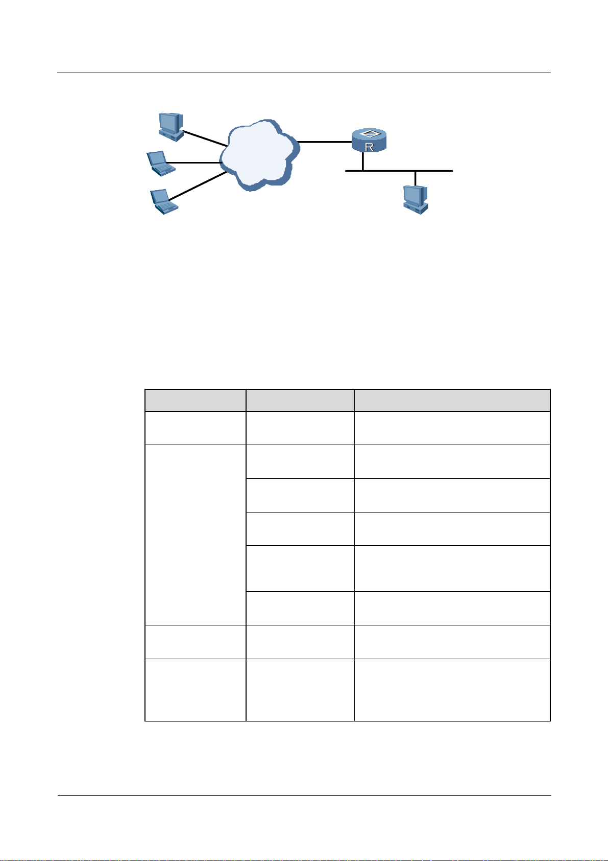
Nortel Secure Router 8000 Series
Troubleshooting - VAS 2 IPSec and IKE troubleshooting
Figure 2-8 Networking diagram of setting up SA using an IPSec policy template
PC C
The networking environment is as follows:
z
Set up an IPSec tunnel between Router A and PC C. The IP address of PC C is uncertain.
z
Set up an SA using an IPSec policy template on Router A.
z
Provide security protection to the data flow between PC A (at 10.1.1.x) and PC C.
z
Specify the security protocol, the encryption algorithm, and the authentication algorithm.
2.4.2 Configuration notes
Item Sub-item Description
Internet
202.38.163.1
GE1/0/1
Router A
10.1.1.X
Ethernet
PC A
10.1.1.2
Configuring the
ACL
Configuring the
IPSec proposal
Configuring the
local ID for IKE
Configuring the
IPSec proposal
Configure the ACL Not required.
Configure the name of
The name is a string of 1 to 15 characters.
the IPSec proposal
Configure the
Transport mode or tunnel mode.
encapsulation mode
Configure the security
AH, ESP, or AH-ESP.
protocols
Configure the
MD5 or SHA-1.
authentication
algorithm
Configure the
DES or 3DES.
encryption algorithm
Configure the local ID
for IKE
Configure the priority
of the IKE proposal
Configuration required only in aggressive
negotiation mode.
This is an integer from 1 to 100, indicating
the priority of a specified IKE proposal.
The lower the value, the higher the
priority.
Issue 01.01 (30 March 2009) Nortel Networks Inc. 2-25

2 IPSec and IKE troubleshooting
Item Sub-item Description
Nortel Secure Router 8000 Series
Troubleshooting - VAS
Configure the
authentication mode
Configure the
authentication
algorithm
Configure the
encryption algorithm
Configure the
Diffie-Hellman group
flag
Configure the
ISAKMP SA duration
Specify pre-shared key for the IKE
proposal authentication mode. You need to
configure the authenticator for pre-shared
key.
By default, the authentication mode is
pre-shared key.
MD5 or SHA-1.
By default, the authentication algorithm is
SHA-1.
DES or 3DES.
By default, the encryption algorithm is
DES.
The Diffie-Hellman group flag can be
group1 (768 bits) or group2 (1024 bits).
By default, use group1 (768 bits) as the
Diffie-Hellman group.
Specify an ISAKMP SA duration.
For configuration notes, see the notes for
“Troubleshooting ISAKMP SA.”
Configuring the IKE
peer
Configure the name of
the IKE peer
Configure the IKE
negotiation mode
Configure the IKE
proposal number
Configure the local ID
type
Configure the
authenticator
Configure the IP
addresses or address
segments of peers
The name is a string of 1 to 15 characters.
Main mode or aggressive mode. By
default, main mode is used.
In main mode, use the configured IKE
proposals.
In aggressive mode, use the default IKE
proposals.
Specify an IKE ID. This can be the IP
address or the name of the IKE peer. In
main mode, the IP address is configured as
the local ID.
By default, the IP address is used.
Currently, only the pre-shared key
authentication type is applicable.
You must configure shared keys on all
peers. The shared key of two ends in the
same SA must be the same.
Configure the IP addresses or address
segments for an IKE peer.
Nortel recommends that you configure an
IP address range for the remote end rather
than specify the IP address.
2-26 Nortel Networks Inc. Issue 01.01 (30 March 2009)

Nortel Secure Router 8000 Series
Troubleshooting - VAS 2 IPSec and IKE troubleshooting
Item Sub-item Description
Configuring the
IPSec policy
template
Configure the peer
name
The name is a string of 1 to 15 characters.
If the local authentication mode is name,
you need to specify the peer name.
Enable NAT By default, NAT is disabled.
Configure the name of
the IPSec policy
template
The name is a string of 1 to 15 characters.
Policies with the same name are in a
policy group. The name and sequence
number define one policy; each policy
group has a maximum of 100 policies.
Parameters of the IPSec policy template
must be the same as those of IPSec
ISAKMP.
Note that parameters such as proposal and
ike-peer are mandatory while other
parameters are optional.
In IKE negotiation, if the IPSec policy
template is used, all configured parameters
on the two ends must match. If no
parameters are configured for an IPSec
policy template, the parameters of the
IPSec policy are the same as those of the
initiator.
Configuring the
IPSec policies and
using the IPSec
policy template
Configure the
sequence number of
the IPSec policy
template
Configure the
negotiation mode
The sequence number of the IPSec policy
template ranges from 1 to 10000.
The lower the sequence number, the
higher the priority.
This is null because you can only use
ISAKMP mode.
Configure the ACL This can be unspecified.
Configure the IPSec
protocol
The security protocol, algorithm, and
encapsulation type must be the same on
two ends of the tunnel.
Configure the IKE
Configure the IKE peer to the policy.
peer
Configure PFS For configuration precautions, see the
configuration notes for “
Troubleshooting
ISAKMP SA.”
Configure the name of
the IPSec policy
The name is a string of 1 to 15 characters.
Policies with the same name are in a
policy group. The name and sequence
number define one policy; each policy
group has a maximum of 100 policies.
Issue 01.01 (30 March 2009) Nortel Networks Inc. 2-27

2 IPSec and IKE troubleshooting
Item Sub-item Description
Nortel Secure Router 8000 Series
Troubleshooting - VAS
Applying the IPSec
policy group
Configure the
sequence number of
the IPSec policy
Configure the
negotiation mode
Use the IPSec policy
template
Configure the
interface type and ID
Configure the name of
the IPSec policy
group
The sequence number ranges from 1 to
10000. The lower the value, the higher the
priority.
Set up SAs in ISAKMP mode.
Use the previously configured IPSec
policy template. The SA set up by a
referential policy template can be the
responder, but not the negotiation initiator.
Enable the IPSec policy group on the
specified group.
For configuration notes, see the notes for
Troubleshooting manual IPSec SA
“
setup .”
Apply one IPSec policy group on one
interface.
For configuration notes, see the notes for
Troubleshooting manual IPSec SA
“
setup .”
The peer PC C with an uncertain IP address must have IPSec capability and must have related
software installed. If the peer is a router, ISAKMP SA should be configured. For details, see
the configuration notes for “
The following sections cover part of the commands for setting up SA using the IPSec policy template.
For more information, see Nortel Secure Router 8000 Series Configuration Guide - Security
(NN46240-600).
Configuring an IKE proposal
Use the default IKE proposal.
Configuring an IKE peer
# Configure the name of the IKE peer to routerb, the negotiation mode to main mode, and the
shared key to nortel. Note that shared keys on two ends must be consistent.
<RouterA> system-view
[RouterA] ike peer routerb
[RouterA-ike-peer-routerb] exchange-mode main
[RouterA-ike-peer-routerb] pre-shared-key nortel
The peer can be without ACL rules. The data to protect is specified in ACL rules on the
negotiation initiator.
Troubleshooting ISAKMP SA.”
2-28 Nortel Networks Inc. Issue 01.01 (30 March 2009)

Nortel Secure Router 8000 Series
Troubleshooting - VAS 2 IPSec and IKE troubleshooting
Configuring an IPSec proposal
# Configure the name of the IPSec proposal to tran1 and the encapsulation type to transport
mode to save bandwidth. Configure the proposal to use the security protocol ESP, the
algorithm SHA-1, and the encryption algorithm DES.
[RouterA] ipsec proposal tran1
[RouterA-ipsec-proposal-tran1] encapsulation-mode transport
[RouterA-ipsec-proposal-tran1] transform esp
[RouterA-ipsec-proposal-tran1] esp authentication-algorithm sha1
[RouterA-ipsec-proposal-tran1] esp encryption-algorithm des
Configuring an IPSec policy template
# Configure the name of the IPSec policy template to maptemp and the sequence number to
10. The ACL is not required. Apply the configured IPSec proposal to the policy and specify
the IKE peer.
[RouterA] ipsec policy-template maptemp 10
[RouterA-ipsec-policy-templet-maptemp-10] proposal tran1
[RouterA-ipsec-policy-templet-maptemp-10] ike-peer C
Configuring an IPSec policy
# Configure the name of IPSec policy to map1, the sequence number to 100, and the
negotiation mode to ISAKMP, and use the IPSec policy template maptemp.
[RouterA] ipsec policy map1 100 isakmp template maptemp
Applying an IPSec policy group
# Apply the IPSec policy map1 on the GE interface.
[RouterA] interface GigabitEthernet 1/0/1
[RouterA-GigabitEthernet1/0/1] ipsec policy map1
Issue 01.01 (30 March 2009) Nortel Networks Inc. 2-29

2 IPSec and IKE troubleshooting
2.4.3 Troubleshooting flowchart
Figure 2-9 Troubleshooting flowchart of setting up IPSec SA using an IPSec policy template
IPSec tunnel fails
Nortel Secure Router 8000 Series
Troubleshooting - VAS
Can two
ends of the tunnel with no IPSec
policy applied ping through
each other ?
Yes
Does the configured
parameters in the policy module
match with those
on the peer?
Yes
Does the
end adopting IPSec policy
module initiate the
negotiation?
Yes
Is the ACL
referred by the peer IPSec
policy of single
rule?
Yes
No
No
No
No
Check the route
检查之间的
and the physical
路
GRE相关配
link
置
Ignore or modify
configured
parameters
Configure the
peer to initiate
the SA
negotiation
Modify the ACL
The fault
disappears?
No
The fault
disappears?
No
The fault
disappears?
No
The fault
disappears?
No
Yes
Yes
Yes
Yes
Is the policy
adopting the IPSec policy
module of a
lowest priority?
Yes
The fault disappears?
Yes
No
No
Modify the
policy's priority.
Seek
technical
support
End
2-30 Nortel Networks Inc. Issue 01.01 (30 March 2009)

Nortel Secure Router 8000 Series
Troubleshooting - VAS 2 IPSec and IKE troubleshooting
2.4.4 Troubleshooting procedure
Step 1 Check whether two ends of the tunnel are reachable with no IPSec policy applied.
Use the undo ipsec policy command on the IPSec tunnel ends.
Close the IPSec client on PC C. Ping PC A from PC C.
A failed ping indicates a faulty route or link between PC A and PC C. For information about
removing the fault, see Nortel Secure Router 8000 Series Troubleshooting - IP Routing
(NN46240-706).
If the ping succeeds, the fault may be related to IPSec. Continue with the following steps.
Step 2 Check that IPSec tunnel setup is not triggered by the communication party applying the IPSec
policy template.
Ping PC A from PC C.
The IP address of PC C is uncertain, so on Router A, the IPSec template specifies no policy
rules. Router A should operate as the negotiation responsor.
Step 3 Check that SAs are set up in Phase 1 and Phase 2.
Refer to the troubleshooting procedure in “
After SA setup succeeds in Phase 1 and Phase 2, continue with the following steps.
Step 4 Check IPSec policies:
z
Check whether the ACL used by the IPSec policy on the negotiation responder contains a
single rule.
If the peer is a PC with an uncertain IP address, the PC should have IPSec capability and
should have the related software installed. The details vary based on the applied software
and are not described here.
If the peer is a router with an uncertain IP address, ensure that the ACL contains a single
rule.
z
The ACL can be unspecified on the end using the IPSec policy template.
On the end using the IPSec policy template, if the peer has an unspecified IP address,
you need not configure the ACL used in the IPSec policy template.
z
The IP address can be unspecified on the end using the IPSec policy template.
On the end that uses the IPSec policy template, if the peer has an unspecified IP address,
you need not configure the IP address or address segment used in the IPSec policy
template.
z
Check whether the priority of the policy that uses the IPSec policy template is the lowest.
Within the same IPSec policy group, check whether the priority of the policy is the
lowest.
You can use the display ipsec policy name command to view details about IPSec policy
groups or the display ipsec policy brief command to view brief information.
<RouterA> display ipsec policy name map1
===========================================
IPsec Policy Group: "map1"
Using local-address: {}
Using interface: {GigabitEthernet1/0/1}
===========================================
Troubleshooting ISAKMP SA.”
Issue 01.01 (30 March 2009) Nortel Networks Inc. 2-31

2 IPSec and IKE troubleshooting
---------------------------- IPsec policy name: "map1"
sequence number: 10
mode: isakmp
---------------------------- security data flow : 3101
ike-peer name: routerc
perfect forward secrecy: None
proposal name: tran2
IPsec sa local duration(time based): 3600 seconds
IPsec sa local duration(traffic based): 1843200 kilobytes
---------------------------- IPsec policy name: "map1"
sequence number: 100
mode: template
---------------------------- policy template name: maptemp
<RouterA> display ipsec policy brief
IPsec-Policy-Name Mode acl ike-peer Local-Address Remote-Address
------------------------------------------------------------------------map1-10 isakmp 3101 routerc
map1-100 template
Nortel Secure Router 8000 Series
Troubleshooting - VAS
Based on the preceding display, view the priorities of the policies; that is, check whether the
sequence number of the policy that uses the IPSec policy template is the highest.
For information about checking other items, see the troubleshooting procedure for
Troubleshooting ISAKMP SA.”
“
If IPSec policies are correct, continue with the following steps.
Step 5 Check whether IPSec can encapsulate or decapsulate packets based on SAs.
Use the debugging ipsec packet command to view IPSec packet encapsulation and
decapsulation.
You can also use the display ipsec statistics command. For details, see the troubleshooting
procedure for “
Troubleshooting ISAKMP SA.”
If the fault remains, contact Nortel technical support.
----End
2.5 Troubleshooting NAT traversal in the IPSec tunnel
This section covers the following topics:
z
Typical networking
z
Configuration notes
z
Troubleshooting flowchart
z
Troubleshooting procedure
2-32 Nortel Networks Inc. Issue 01.01 (30 March 2009)

Nortel Secure Router 8000 Series
Troubleshooting - VAS 2 IPSec and IKE troubleshooting
2.5.1 Typical networking
Figure 2-10 shows the networking diagram of NAT traversal in the IPSec tunnel.
Figure 2-10 Networking diagram of IPSec NAT
Router A
10.1.1.1
PC A
Eth1/0/1
202.38.163.1
Firewall C
Eth0/ 0/1
202.38.162. 10
Internet
Eth2/0/1
202.38.162.1
Router B
10.1.2.1
10.1.2.210.1.1.2
PC B
The networking environment is as follows:
z
A firewall (Firewall C) exists between Router A and Router B.
z
Create a security tunnel between Router A and Router B.
z
Set up SAs using an IPSec policy template.
z
Provide security protection to the data flow between the subnetwork segments 10.1.1.x
and 10.1.2.x.
z
Specify the security protocol, the encryption algorithm, and the authentication algorithm.
2.5.2 Configuration notes
The internal NAT network uses the normal ISAKMP SA configurations. The following table
lists the notes and constraints.
Item Sub-item Description
Configuring the
ACL
IPSec proposal
Configure the
ACL number
Configure other
items
Configure the
IPSec proposal
name
Configure the
encapsulation
mode
Use the advanced ACL, ranging from 3000 to
3999.
For configuring the internal NAT network, see
Troubleshooting ISAKMP SA.” You must
“
configure the ACL.
See the configuration notes for “
Troubleshooting
ISAKMP SA.”
The name is a string of 1 to 15 characters. Configuring the
This must be tunnel mode.
Issue 01.01 (30 March 2009) Nortel Networks Inc. 2-33

2 IPSec and IKE troubleshooting
Item Sub-item Description
Nortel Secure Router 8000 Series
Troubleshooting - VAS
Configuring the
local ID for IKE
Configuring the
IPSec proposal
Configuring the
IKE peer
Configure other
items
Configure the
local ID for IKE
See the configuration notes for “Troubleshooting
ISAKMP SA.”
You must configure a local ID for IKE because
NAT traversal uses aggressive IKE negotiation
and the local name is configured as the local
authentication type.
— See the configuration notes for “Troubleshooting
ISAKMP SA.”
Configure the
The name is a string of 1 to 15 characters.
IKE peer name
Configure the
Use aggressive negotiation mode.
IKE negotiation
mode
Configure the
Use the default IKE proposal in aggressive mode.
sequence number
of IKE proposals
Configure the
Specify the local name as the local ID.
local ID type
Configure the
authenticator
Currently, only the pre-shared key authentication
type is applicable.
You must configure shared keys on the peer. The
shared keys of two ends in the same SA must be
the same.
Configuring the
IPSec policy
Configure the IP
address or address
segments of the
peer
Configure the IP addresses or address segments
for the IKE peer. If high-ip-address is not
specified, configure only one IP address for the
IKE peer.
Here, the IP address of the peer must be a unique
address because the IPSec policy template does
not use the IKE peer.
To configure IP addresses or address segments for
peers, run the remote-address [ vpn-instance
vpn-instance-name ] low-ip-address
[ high-ip-address ] command in the IKE proposal
view.
Configure the
peer name
The name is a string of 1 to 15 characters.
If the local authentication mode is “name,” you
must specify the peer name.
Enable NAT Enable NAT.
— See the configuration notes for “Troubleshooting
ISAKMP SA.”
2-34 Nortel Networks Inc. Issue 01.01 (30 March 2009)

Nortel Secure Router 8000 Series
Troubleshooting - VAS 2 IPSec and IKE troubleshooting
Item Sub-item Description
Applying the
IPSec policy
— See the configuration notes for “Troubleshooting
ISAKMP SA.”
group
For configuring the external NAT network, see “
Troubleshooting SA setup using an IPSec
policy template.” The following table lists the notes and constraints.
Item Sub-item Description
Configuring the
ACL
Configuring the
IPSec proposal
— Configure the external NAT network using the
template. ACL configuration is not required.
Configure the
The name is a string of 1 to 15 characters.
IPSec proposal
name
Configure the
This must be tunnel mode.
encapsulation
mode
Configuring the
local ID for IKE
Configure other
items
Configure the
local ID for IKE
See the configuration notes for “
ISAKMP SA.”
You must configure the local ID because NAT
traversal uses aggressive IKE negotiation and the
local name is configured as the local
authentication type.
Troubleshooting
Configuring the
IPSec proposal
Configuring the
IKE peer
— See the configuration notes for “Troubleshooting
ISAKMP SA.”
Configure the
The name is a string of 1 to 15 characters.
IKE peer name
Configure the
Use aggressive negotiation mode.
IKE negotiation
mode
Configure the
Use the default IKE proposal in aggressive mode.
sequence number
of IKE proposals
Configure the
Specify the local name as the local ID.
local ID type
Configure the
authenticator
Currently, only the pre-shared key authentication
type is applicable.
You must configure shared keys on the peer. The
shared keys of two ends in the same SA must be
the same.
Issue 01.01 (30 March 2009) Nortel Networks Inc. 2-35

2 IPSec and IKE troubleshooting
Item Sub-item Description
Nortel Secure Router 8000 Series
Troubleshooting - VAS
Configuring the
IPSec policy
template
Configuring the
IPSec policies
and applying the
IPSec policy
template
Configure the IP
addresses or
address segments
of the peer
Configure the IP addresses or address segments for
an IKE peer. If high-ip-address is not specified,
configure only one IP address for an IKE peer.
Here, the IP address of the peer must be a unique
address because the IPSec policy template does
not use the IKE peer.
To configure IP addresses or address segments for
peers, run the remote-address [ vpn-instance
vpn-instance-name ] low-ip-address
[ high-ip-address ] command in the IKE proposal
view.
Configure the
peer name
The name is a string of 1 to 15 characters.
If the local authentication mode is “name,” you
must specify the peer name.
Enable NAT Enable NAT.
— See the configuration notes for “Troubleshooting
SA setup using an IPSec policy template.”
— See the configuration notes for “
Troubleshooting
SA setup using an IPSec policy template.”
Firewall C
Router A
Applying the
IPSec policy
— See the configuration notes for “Troubleshooting
SA setup using an IPSec policy template.”
group
Configure Router A, Firewall C, and Router B.
The commands listed in the following sections cover part of IPSec configuration. For more information,
see Nortel Secure Router 8000 Series Configuration Guide - Security (NN46240-600).
Configure routes and an address pool with addresses from 202.38.162.11 to 202.38.162.20 on
Firewall C. Enable NAT on the egress Ethernet 0/0/1.
For information about firewall configuration, see the related firewall configuration documentation.
For detailed configuration information and precautions, see the configuration notes for
“
Troubleshooting ISAKMP SA.”
1. Configure the IKE local ID.
2-36 Nortel Networks Inc. Issue 01.01 (30 March 2009)

Nortel Secure Router 8000 Series
Troubleshooting - VAS 2 IPSec and IKE troubleshooting
# Configure the host local ID in aggressive IKE negotiation mode.
<RouterA > system-view
[RouterA] ike local-name routera
2. Configure IKE proposals.
By default, use the default IKE proposals.
3. Configure the IKE peer.
# Configure the name of the IKE peer to routerb. Configure aggressive negotiation mode
and set “name” as the local ID authentication type. Preset the shared key to nortel.
Configure an IP address 202.38.162.1 for the peer and enable NAT on it.
Note the following:
z
The shared keys configured on the connected peer must be consistent.
z
“Name” is used as the ID authentication type. The remote name must be the same as the
local IKE ID configured on the peer through the ike local-name command.
[RouterA] ike peer routerb
[RouterA-ike-peer-routerb] exchange-mode aggressive
[RouterA-ike-peer-routerb] local-id-type name
[RouterA-ike-peer-routerb] pre-shared-key nortel
[RouterA-ike-peer-routerb] remote-name routerb
[RouterA-ike-peer-routerb] remote-address 202.38.162.1.
[RouterA-ike-peer-routerb] nat traversal
4. Configure an ACL.
# Configure an ACL, specifying the data flow from 10.1.1.x to 10.1.2.x..
[RouterA] acl number 3101
[RouterA-acl-adv-3101] rule permit ip source 10.1.1.0 0.0.0.255 destination 10.1.2.0
0.0.0.255
5. Configure an IPSec proposal.
# Configure the name of IPSec proposal to tran1. The proposal uses the tunnel mode,
SHA-1 authentication algorithm, and DES encryption algorithm.
[RouterA] ipsec proposal tran1
[RouterA-ipsec-proposal-tran1] encapsulation-mode tunnel
[RouterA-ipsec-proposal-tran1] transform esp
[RouterA-ipsec-proposal-tran1] esp authentication-algorithm sha1
[RouterA-ipsec-proposal-tran1] esp encryption-algorithm des
6. Configure an IPSec policy.
# Configure the name of IPSec policy to map1, the sequence number to 10, and the
negotiation mode to ISAKMP. Apply the configured IPSec proposal tran1 to the policy,
and configure the IKE peer to routerb.
[RouterA] ipsec policy map1 10 isakmp
[RouterA-ipsec-policy-isakmp-map1-10] security acl 3101
[RouterA-ipsec-policy-isakmp-map1-10] proposal tran1
[RouterA-ipsec-policy-isakmp-map1-10] ike-peer routerb
7. Apply the IPSec policy.
# Apply the IPSec policy map1 on the serial interface.
[RouterA] interface Ethernet 1/2/0
Issue 01.01 (30 March 2009) Nortel Networks Inc. 2-37

2 IPSec and IKE troubleshooting
[RouterA-Ethernet1/2/0] ipsec policy map1
Router B
For information about configuring Router B, see the configuration notes for “Troubleshooting
SA setup using an IPSec policy template.”
1. Configure the local ID for IKE.
# Configure the local ID of the host in aggressive IKE negotiation mode.
<RouterB> system-view
[RouterB] ike local-name routerb
2. Configure IKE proposals.
If no proposal is configured, the remote IKE ends use the default IKE proposals.
3. Configure the IKE peer.
# Configure the name of the IKE peer to routera, use aggressive negotiation mode, set
“name” as the local ID authentication type, and preset the shared key to nortel. Enable
NAT on it.
Nortel Secure Router 8000 Series
Troubleshooting - VAS
Note the following:
z
The shared keys configured on the connected peer must be consistent.
z
“Name” is used as the ID authentication type. The remote name must be the same as the
local IKE ID configured on the peer through the ike local-name command.
z
You need not configure the remote IP address.
[RouterB] ike peer routera
[RouterB-ike-peer-routera] exchange-mode aggressive
[RouterB-ike-peer-routera] local-id-type name
[RouterB-ike-peer-routera] pre-shared-key nortel
[RouterB-ike-peer-routera] remote-name routera
[RouterB-ike-peer-routera] nat traversal
4. Configure an ACL.
No ACL is configured; that is, the data to protect is unspecified but defined in the ACL
rules of the negotiation initiator.
5. Configure an IPSec proposal.
# Configure the name of IPSec proposal to tran1. The proposal uses the tunnel mode,
SHA-1 authentication algorithm, and DES encryption algorithm.
[RouterB] ipsec proposal tran1
[RouterB-ipsec-proposal-tran1] encapsulation-mode tunnel
[RouterB-ipsec-proposal-tran1] transform esp
[RouterB-ipsec-proposal-tran1] esp authentication-algorithm sha1
[RouterB-ipsec-proposal-tran1] esp encryption-algorithm des
6. Configure an IPSec policy template.
# Configure the name of the IPSec policy template to maptemp and the sequence number
to 10. The ACL is not required. Use the configured IPSec proposal tran1 and configure
the IKE peer to routerb.
[RouterB] ipsec policy-template maptemp 10
[RouterB-ipsec-policy-templet-maptemp-10] proposal tran1
2-38 Nortel Networks Inc. Issue 01.01 (30 March 2009)

Nortel Secure Router 8000 Series
Troubleshooting - VAS 2 IPSec and IKE troubleshooting
[RouterB-ipsec-policy-templet-maptemp-10] ike-peer routerb
7. Configure an IPSec policy.
# Configure the name of the IPSec policy to map1, the sequence number to 100, and the
negotiation mode to ISAKMP. Use the IPSec policy template maptemp.
[RouterB] ipsec policy map1 100 isakmp template maptemp
8. Apply the IPSec policy group.
# Apply the IPSec policy map1 on the Ethernet interface.
[RouterB] interface Ethernet 2/1/0
[RouterB-Ethernet1/2/0] ipsec policy map1
Configuring routes
On Router B, there should be a route to 10.1.1.0/24 with the egress as Ethernet 2/0/1.
After IPSec packets are decapsulated, the original IP packets are displayed. NAT fails because
the original IP packets are encrypted through the ESP protocol. Packets still use the IP address
that has not been translated by the firewall. When the response packets reach Router B and
find no routes to the destination, they cannot be forwarded through the IPSec tunnel.
Issue 01.01 (30 March 2009) Nortel Networks Inc. 2-39

2 IPSec and IKE troubleshooting
2.5.3 Troubleshooting flowchart
Figure 2-11 Troubleshooting flowchart of NAT traversal in IPSec
IPSec tunnel
fails
Nortel Secure Router 8000 Series
Troubleshooting - VAS
Can tunnel ends
with no IPSec policy ping
through each other ?
Yes
Is IKE
negotiation in Phase 1 in
aggressive mode?
Yes
Is name
configured as the peer ID
authentication type
Yes
Is NAT enabled on IKE peers?
Yes
Is ESP adopted
in IPSec proposals?
Yes
No
?
No
Check the route
and the physical
link between them
Modify the
No
negotiation mode
in Phase 1
Modify the ID
No
authentication
type
No
Enable NAT
No
Modify the
adopted protocol
type
The fault
disappears?
No
The fault
disappears?
No
The fault
disappears?
No
The fault
disappears?
No
The fault
disappears?
No
Yes
End
End
Yes
Yes
End
Yes
End
Yes
End
Is the
tunnel mode adopted in IPSec
proposals?
Yes
The fault disappears?
Yes
End
No
No
Modify the
adopted
encapsulation type
The fault
disappears?
No
Seek
technical
support
Yes
End
2-40 Nortel Networks Inc. Issue 01.01 (30 March 2009)

Nortel Secure Router 8000 Series
Troubleshooting - VAS 2 IPSec and IKE troubleshooting
2.5.4 Troubleshooting procedure
Step 1 Check whether two ends of the tunnel are reachable with no IPSec policy applied.
Use the undo ipsec policy command on both the ends of the IPSec tunnel.
On PC A, ping PC B.
A failed ping indicates a faulty link or route between PC A and PC B. For information about
removing the fault, see Nortel Secure Router 8000 Series Troubleshooting - IP Routing
(NN46240-706).
If the ping succeeds, the fault may be related to IPSec. Continue with the following steps.
Step 2 Ensure that IPSec tunnel setup is not triggered by the communication party applying the
IPSec policy template.
Ping PC B from PC A. The IPSec template used by Router B specifies no policy rules, so
Router B can operate only as the negotiation responsor.
Continue with the following steps.
Step 3 Check that SAs are set up in Phase 1 and Phase 2.
See the troubleshooting procedure for “
Troubleshooting ISAKMP SA.”
Continue with the following steps.
Step 4 Check that IKE peer configurations agree with the constraint conditions.
Check the following:
z
whether the negotiation in Phase 1 is in aggressive mode
z
whether the peer name is used as the local ID type
z
whether NAT is enabled on the IKE peer
Use the display ike peer name command.
<RouterA> display ike peer name routerb
-------------------------- IKE Peer: routerb
exchange mode: aggressive on phase 1
pre-shared-key: nortel
proposal:
local id type: name
peer ip address: 202.38.162.1
peer name: routerb
nat traversal: enable
---------------------------
Use the preceding command on Router A and Router B to view the constraint conditions. If
the IKE peer configurations are correct, continue with the following steps.
Step 5 Check that IPSec proposals agree with the constraint conditions.
Check the following:
z
whether ESP is used in IPSec proposals
z
whether the encapsulation type is transport mode
Issue 01.01 (30 March 2009) Nortel Networks Inc. 2-41

2 IPSec and IKE troubleshooting
Use the display ipsec proposal name command to view if the specified IPSec proposals on
two ends are the same.
<RouterA> display ipsec proposal name tran1
IPsec proposal name: tran1
encapsulation mode: tunnel
transform: esp-new
ESP protocol: authentication sha1-hmac-96, encryption des
Use the preceding command on Router A and Router B to view the constraint conditions. If
the IPSec proposals are correct, continue with the following steps.
Step 6 Check that IPSec can encapsulate or decapsulate inbound and outbound packets.
Use the debugging ipsec packet command to view if IPSec can encapsulate or decapsulate
packets.
You can also use the display ipsec statistics command to view IPSec statistics. See the
troubleshooting procedure for “
Step 7 Check that IPSec tunnel ends in the external and internal NAT network are routable.
If Router B has no route to 10.1.1.0/24, use the debugging ipsec packet and the display ipsec
statistics commands to determine the following:
Nortel Secure Router 8000 Series
Troubleshooting - VAS
Troubleshooting ISAKMP SA.”
z
Router A can send the encapsulated IPSec packets but cannot decapsulate packets.
z
Router B can receive and decapsulate IPSec packets but cannot encapsulate packets.
In this case, you need to specify a route to 10.1.1.0/24 on Router B.
In the internal NAT network, Router A uses the private IP address. It is not advisable to configure a
private route from Router B to Router A. In an actual application, PC A and PC B are configured with
loopback addresses.
If the fault persists, contact Nortel technical support.
----End
2.6 Troubleshooting GRE over IPSec or L2TP over IPSec
This section covers the following topics:
z
Typical networking
z
Configuration notes
z
Troubleshooting flowchart
z
Troubleshooting procedure
2.6.1 Typical networking
The basic concepts of GRE over IPSec and L2TP over IPSec are the same. That is, the tunnel
is first encapsulated with GRE or L2TP and then with IPSec. The processing of IPSec packets
and common IP packets is almost the same. In practice, IPSec packets are the data transmitted
on two IPSec tunnel ends.
Figure 2-12 shows GRE over IPSec. The troubleshooting procedure is based on this diagram.
2-42 Nortel Networks Inc. Issue 01.01 (30 March 2009)

Nortel Secure Router 8000 Series
Troubleshooting - VAS 2 IPSec and IKE troubleshooting
Figure 2-12 Networking diagram of configuring IPSec
Router
10.1.1.1
10.1.1.2
A
PC
A
Pos1/0/1
202.38.163.1
Internet
IPSe
c
Pos2/0/1
202.38.162.1
GREIPSec
Router
B
10.1.2.1
10.1.2.2
PC
B
The networking environment is as follows:
z
Create a GRE tunnel between Router A and Router B.
z
Create an IPSec tunnel between Router A and Router B to protect packets forwarded
through the GRE tunnel.
z
Specify the data flow between subnetwork segments 10.1.1.x and 10.1.2.x to pass the
GRE tunnel.
z
Set up IPSec SAs in ISAKMP mode.
2.6.2 Configuration notes
Item Sub-item Description
Configuring the
GRE tunnel
Configuring the
ACL
Configure the tunnel type Configure a GRE tunnel.
Configure the source IP
address of the tunnel
Configure the destination
IP address of the tunnel
Configure the ACL number Use the advanced ACL, ranging from
Configure the protocol ID
specified in the ACL
Configure the source and
destination addresses
specified in ACL rules
For configuration notes, see the section
about GRE troubleshooting in Nortel
Secure Router 8000 Series
Troubleshooting - VPN (NN46240-710).
For configuration notes, see the section
about GRE troubleshooting in Nortel
Secure Router 8000 Series
Troubleshooting - VPN (NN46240-710).
3000 to 3999.
The protocol ID of GRE.
The source and destination IP addresses of
the GRE tunnel.
Configure other items in
Not required.
ACL rules
Issue 01.01 (30 March 2009) Nortel Networks Inc. 2-43

2 IPSec and IKE troubleshooting
Item Sub-item Description
Nortel Secure Router 8000 Series
Troubleshooting - VAS
Configuring the
IPSec proposal
Configuring the
local ID for
IKE
Configuring the
IKE proposals
Configuring the
IKE peer
Configuring the
IPSec policy
Applying the
IPSec policy
Configure the number of
Configure only one ACL rule.
ACL rules
Configure the name of
The name is a string of 1 to 15 characters.
the IPSec proposal
Configure the
encapsulation mode
Transport mode or tunnel mode.
To save bandwidth, transport mode is
preferred.
Configure other items See “
Troubleshooting ISAKMP SA.”
— See “Troubleshooting ISAKMP SA”.
— See “Troubleshooting ISAKMP SA.”
— See “Troubleshooting ISAKMP SA.”
— See “Troubleshooting ISAKMP SA.”
Configure the type and
number of interfaces
Enable IPSec on the physical interfaces on
a GRE tunnel. The source and the
destination IP addresses of the tunnel must
not be loopback addresses.
IPSec over GRE supports applying a
policy group to GRE virtual interfaces.
Router A serves as an example of the configuration notes for GRE over IPSec. Router B and
Router A are mutually mirroring.
The following sections cover part of the commands used to configure IPSec. For more information, see
Nortel Secure Router 8000 Series Configuration Guide - Security (NN46240-600).
Configuring a GRE tunnel
# Encapsulate the tunnel with GRE. Configure the IP addresses for the source and destination
tunnel ends. Note that the two addresses cannot be loopback addresses.
<RouterA> system-view
[RouterA] interface tunnel 1/0/1
[RouterA-Tunnel1/0/1] tunnel-protocol gre
[RouterA-Tunnel1/0/1] source 202.38.163.1
Configure the IPSec policy
group name
Apply only one IPSec policy group on one
interface.
For configuration notes, see
Troubleshooting ISAKMP SA.”
“
2-44 Nortel Networks Inc. Issue 01.01 (30 March 2009)

Nortel Secure Router 8000 Series
Troubleshooting - VAS 2 IPSec and IKE troubleshooting
[RouterA-Tunnel1/0/1] destination 202.38.162.1
Configuring IKE proposals
If no IKE proposal is configured, the remote end uses default IKE proposals.
Configuring the IKE peer
# Configure the name of the IKE peer to routerb and use aggressive negotiation mode. Preset
the shared key to nortel. Note that the shared keys configured on two ends must be consistent.
Configure an IP address 202.38.162.1 for the remote end.
[RouterA] ike peer routerb
[RouterA-ike-peer-routerb] exchange-mode agressive
[RouterA-ike-peer-routerb] pre-shared-key nortel
[RouterA-ike-peer-routerb] remote-address 202.38.162.1
Configuring an ACL
# Configure an ACL, defining the protected GRE packets.
[RouterA] acl number 3101
[RouterA-acl-adv-3101] rule permit gre source 202.38.163.1 0 destination 202.38.162.1
0
Configuring an IPSec proposal
# Configure the name of the IPSec proposal to tran1 and use transport mode to save
bandwidth. The policy uses the ESP security protocol, the SHA-1 authentication algorithm,
and the DES encryption algorithm.
[RouterA] ipsec proposal tran1
[RouterA-ipsec-proposal-tran1] encapsulation-mode transport
[RouterA-ipsec-proposal-tran1] transform esp
[RouterA-ipsec-proposal-tran1] esp authentication-algorithm sha1
[RouterA-ipsec-proposal-tran1] esp encryption-algorithm des
Configuring an IPSec policy
# Configure the name of IPSec policy to map1, the sequence number to 10, and the
negotiation mode to ISAKMP. Apply the configured ACL and IPSec proposal tran1 to the
policy. Configure the IKE peer to routerb.
[RouterA] ipsec policy map1 10 isakmp
[RouterA-ipsec-policy-isakmp-map1-10] security acl 3101
[RouterA-ipsec-policy-isakmp-map1-10] proposal tran1
[RouterA-ipsec-policy-isakmp-map1-10] ike-peer routerb
Applying the IPSec policy group
# Apply the IPSec policy group map1 on the specified interface.
Note that the interface should be the physical interface on the tunnel with the source address
202.38.163.1. It should not be the GRE virtual interface tunnel 1/0/1.
[RouterA] interface Pos 1/0/1
[RouterA-Pos1/0/1] ipsec policy map1
Issue 01.01 (30 March 2009) Nortel Networks Inc. 2-45

2 IPSec and IKE troubleshooting
2.6.3 Troubleshooting flowchart
Figure 2-13 Troubleshooting flowchart of GRE over IPSec
GRE over
IPSec fails
Nortel Secure Router 8000 Series
Troubleshooting - VAS
Can tunnel
endsapplying no IPSec
policy ping through each
other ?
Yes
Are the source
and the destination IP
addresses specified in
the ACL just addresses of
GRE tunnel ends?
Yes
Are GRE tunnel
ends loopback interfaces
No
or with loopback
addresses?
No
Is the IPSec
policy group applied on
GRE tunnel ends?
Check routes,
No
physical links and
GRE configurations
Modify the source
No
and the destination
IP addresses in the
ACL.
Modify the ports
No
because GRE over
IPSec does not
support loopback
interfaces
Apply IPSec policy
No
to the specified
interface
The fault
disappears?
No
The fault
disappears?
No
The fault
disappears?
No
The fault
disappears?
Yes
End
Yes
End
Yes
End
Yes
End
Yes
Are SAs set up manually?
Yes
Are SAs set up
in ISAKMP mode?
Yes
The fault disappears?
Yes
End
No
No
Refer to manual
troubleshooting
Refer to ISAKMP
troubleshooting.
No
IPSec SA
IPSec SA
No
The fault
disappears?
No
The fault
disappears?
No
Seek technical
support
Yes
End
Yes
End
2-46 Nortel Networks Inc. Issue 01.01 (30 March 2009)

Nortel Secure Router 8000 Series
Troubleshooting - VAS 2 IPSec and IKE troubleshooting
2.6.4 Troubleshooting procedure
Step 1 Check whether the tunnel is reachable with no IPSec policy applied.
As shown in
Figure 2-12, use the undo ipsec policy command to disable the IPSec policy on
Router A and Router B. The packets are forwarded through the GRE tunnel.
On PC A, ping PC B.
If the ping succeeds, the route, the link, and the GRE tunnel between PC A and PC B are
normal. The fault may be caused by the IPSec configuration. Proceed to Step 2.
If the ping fails, modify the configuration so the packets from PC A to PC B do not pass the
GRE tunnel.
z
If the ping still fails after the modification, it indicates that a fault occurs on the route or
the link between PC A and PC B is incorrect.
z
If the ping succeeds and the GRE tunnel is unused after the modification, the fault is
caused by an incorrectly configured GRE tunnel. For information about removing the
fault, see the section about GRE troubleshooting in Nortel Secure Router 8000 Series
Troubleshooting - VPN (NN46240-710).
Step 2 Check whether SAs are set up in Phase 1 and Phase 2.
See the troubleshooting procedure for “
Troubleshooting ISAKMP SA.”
If SAs are configured in Phase 1 and Phase 2, continue with the following steps.
Step 3 Check IPSec policies.
Check the following:
z
whether GRE tunnel ends are loopback interfaces or whether they are configured with
loopback addresses (GRE over IPSec does not support loopback interfaces)
z
whether the source and destination IP addresses specified in the ACL agree with the
addresses of GRE tunnel ends
z
whether the IPSec policy group is applied on interfaces where GRE tunnel ends are
located
For details, see the troubleshooting procedure for “
Troubleshooting ISAKMP SA.”
If the IPSec policies are correct, continue with the following steps.
Step 4 Check whether IPSec can encapsulate or decapsulate packets.
Use the debugging ipsec packet command to view whether IPSec can encapsulate and
decapsulate packets based on SAs.
You can also use the display ipsec statistics command to view IPSec statistics. For details,
see the troubleshooting procedure “
Troubleshooting ISAKMP SA.”
If the fault persists, contact Nortel technical support.
----End
Issue 01.01 (30 March 2009) Nortel Networks Inc. 2-47

2 IPSec and IKE troubleshooting
2.7 Troubleshooting cases
Fault symptom
Figure 2-14 shows a diagram of IPSec SA setup in ISAKMP mode.
Figure 2-14 Networking diagram of IPSec setup
Nortel Secure Router 8000 Series
Troubleshooting - VAS
Fault analysis
Router A
10.1.1.1
Pos1/0/1
202.38.163.1
Internet
Pos2/0/1
202.38.162.1
Router B
10.1.2.1
10.1.2.210.1.1.2
After Router A is restarted, the IPSec tunnel fails.
z
Use the debugging ipsec packet command on Router B. IPSec packets sent from Router
B to Router A can be encapsulated.
z
Use the debugging ipsec packet command on Router A. Packet decapsulation on Router
A fails.
z
Use the display ipsec sa command on Router A and Router B. You cannot find the SA on
Router A.
The cause for this fault may be that the default timeout period for the ISAKMP SA to wait for
Keep Alive packets is not configured. After Router A is restarted, Router B is not notified to
remove the corresponding SA. Router B continues to use the previous SA.
Enable the keep-alive function of ISAKMP SA to remove this fault. If the SA duration
exceeds the keep-alive value, remove SAs on both ends and reinitiate a negotiation.
Troubleshooting procedure
Step 1 Use the reset ipsec sa command or the reset ike sa command in the system view to remove
the corresponding SA from Router B.
Step 2 Use the ike sa keepalive-timer interval second command in the system views of Router A
and Router B to specify the interval at which Keep Alive packets are sent.
Step 3 Use the ike sa keepalive-timer timeout seconds command in the system views of Router A
and Router B to specify the timeout period for waiting for Keep Alive packets sent from the
peer of ISAKMP SA.
Step 4 Save the configuration.
After completing the previous steps, the IPSec tunnel can operate normally.
----End
2-48 Nortel Networks Inc. Issue 01.01 (30 March 2009)

Nortel Secure Router 8000 Series
Troubleshooting - VAS 2 IPSec and IKE troubleshooting
Summary
If the keep-alive function of ISAKMP SA is disabled, you must remove the related SA
manually after the device is restarted.
2.8 FAQs
Q: In an unstable network, SAs cannot be set up or SAs are set up but the
communication between peers fails although the ACLs have matching security
proposals. Why?
A: The possible cause is that the router on one end restarts after SAs are set up.
z
Use the display ike sa command to check whether IKE SAs in Phase 1 are set up on
peers.
z
Use the display ipsec sa policy command to check whether IPSec SAs are set up on the
interfaces.
z
If the output shows that only one end is configured with an SA, use the reset ike sa
command to remove the SA and initiate a new negotiation.
Q. During IPSec debugging, the message "Got NOTIFY of type
NO_PROPOSAL_CHOSEN or drop message from A.B.C.D due to notification
type NO_PROPOSAL_CHOSEN" is displayed. What does this indicate?
A: The possible cause is that the negotiation ends have no matched proposal.
z
Check whether the IKE proposals on two ends are matched in Phase 1 negotiation.
z
Check whether the IPSec policy parameters, the IPSec proposals, the encryption
algorithm, and the authentication algorithm applied on two ends are matched in Phase 2
negotiation.
Q. How do I validate modified IPSec or IKE configurations?
A: If you modify IPSec or IKE parameters, such as parameters of IKE proposals, IKE peers,
or IPSec proposals, reapply the IPSec policy to the interface and then use the reset ike sa
command in the user view to validate the configuration.
Q: Is the IPSec tunnel the same as the SA?
A: The IPSec tunnel and SA are different. The IPSec tunnel is bidirectional while an SA is
unidirectional. An IPsec tunnel consists of two SAs with reverse directions.
Q: What are guidelines for ACL used in IPSec?
A: The guidelines are as follows:
z
Only the data flows matching ACL rules are protected.
z
Configure an ACL as required to permit data flows.
z
Avoid setting the keyword any randomly.
Issue 01.01 (30 March 2009) Nortel Networks Inc. 2-49

Nortel Secure Router 8000 Series
2 IPSec and IKE troubleshooting
z
The local and remote ACLs must be mutually mirrored. (When the IPSec policy template
is used, this item can be ignored.)
Troubleshooting - VAS
Q: Can AH and ESP be used at the same time?
A: They can be used either separately or together. If they are used together, the user is
authenticated twice. Nortel recommends that you do not use them at the same time.
Q: Can ESP perform only packet encryption but not authentication?
A: Nortel recommends that you do not send unauthenticated packets.
Q: Can transport mode be used when the communication port and IPSec tunnel
port are different?
A: In transport mode, if the protected data flow is not on the IPSec tunnel port (that is, the
protected flow is not on any end of the tunnel), it cannot be securely protected.
Q: What are the constraints on configuring encryption and authentication shared
keys manually?
A: The constraints are as follows:
z
The shared key on the local inbound should be the same as that on the outbound of the
peer.
z
The shared key on the local outbound should be the same as that on the inbound of the
peer.
z
The shared keys on the two ends should be in the same format. For example, if on one
end, the shared key is a character string, it cannot be a hexadecimal numeral on the
remote end. If they are not in the same format, the IPSec tunnel setup fails.
Q: Can an SA that is set up using an IPSec policy template initiate an SA
negotiation?
A: The SA cannot be the negotiation initiator but it can be the responder.
Q: Why do I not need to specify the local IP address in the IPSec tunnel?
A: You can use the interface address as the local IP address after applying the IPSec policy on
an interface.
2.9 Diagnostic tools
2.9.1 Display commands
Command Description
display ipsec proposal name
display ipsec policy name
2-50 Nortel Networks Inc. Issue 01.01 (30 March 2009)
Displays the IPSec protocol.
Displays the IPSec policy.

Nortel Secure Router 8000 Series
Troubleshooting - VAS 2 IPSec and IKE troubleshooting
Command Description
display ipsec sa policy
display ipsec sa brief
display ike proposal
display ike peer name
display ike sa
display ipsec statistics
display ipsec proposal name
<RouterA> display ipsec proposal name tran1
IPsec proposal name: tran1
encapsulation mode: tunnel
transform: ah-esp-new
AH protocol: authentication sha1-hmac-96
ESP protocol: authentication sha1-hmac-96, encryption 3des
encapsulation mode: tunnel
The display indicates two IPSec packet encapsulation types: transport mode and tunnel mode.
You can use the encapsulation-mode { transport | tunnel } command to modify the
configuration.
Displays the SA associated with the IPSec policy.
Displays brief information about the IPSec SA.
Displays the IKE protocol.
Displays the IKE peer.
Displays the IKE SA.
Displays IPSec statistics.
transform: ah-esp-new
The display indicates the security protocols in the IPSec proposal: AH, ESP, and AH-ESP.
You can use the transform { ah | esp | ah-esp } command to modify the configuration.
AH protocol: authentication sha1-hmac-96
The display indicates the authentication algorithms in the AH protocol: SHA-1 (sha1-hmac-96)
and MD5 (md5-hmac-96).
You can use the ah authentication-algorithm { md5 | sha1 } command to modify the
configuration.
ESP protocol: authentication sha1-hmac-96, encryption 3des
The display indicates the authentication algorithms and encryption algorithms in ESP. The
authentication algorithms are SHA-1 and MD5 and the encryption algorithms are DES and
3DES.
You can use the esp authentication-algorithm { md5 | sha1 } command and the esp
encryption-algorithm { 3des | des } command to modify the configuration.
display ipsec policy name
z
IPSec policies manually configured:
<RouterA> display ipsec policy name map1
===========================================
IPsec Policy Group: "map1"
Issue 01.01 (30 March 2009) Nortel Networks Inc. 2-51

2 IPSec and IKE troubleshooting
Using local-address: {}
Using interface: {Ethernet0/2/0}
===========================================
---------------------------- IPsec policy name: "map1"
sequence number: 10
mode: manual
---------------------------- security data flow : 3101
tunnel local address: 202.38.163.1
tunnel remote address: 202.38.162.1
proposal name:tran1
inbound AH setting:
AH spi:
AH string-key:
AH authentication hex key:
inbound ESP setting:
ESP spi: 54321 (0xd431)
ESP string-key: gfedcba
ESP encryption hex key:
ESP authentication hex key:
outbound AH setting:
AH spi:
AH string-key:
AH authentication hex key:
outbound ESP setting:
ESP spi: 12345 (0x3039)
ESP string-key: abcdefg
ESP encryption hex key:
ESP authentication hex key:
Using interface: {Ethernet0/2/0}
Nortel Secure Router 8000 Series
Troubleshooting - VAS
The display indicates the interface that uses the IPSec policy group.
You can use the ipsec policy command to change the interface that uses IPSec policies.
mode: manual
The display indicates two IPSec policy modes: manual mode and ISAKMP mode.
You can use the ipsec policy policy-name seq-number { manual | isakmp } command to
configure IPSec policies.
security data flow : 3101
The display indicates the ACL used in the IPSec policy.
You can use the security acl command to modify the configuration.
tunnel local address: 202.38.163.1
The display indicates the local address of IPSec tunnel. This address is the address of the
interface that uses the IPSec policy group.
tunnel remote address: 202.38.162.1
The display indicates the IP address of the remote end on the IPSec tunnel. You need to
configure this address only for the manually set up IPSec SA.
You can use the tunnel remote command to modify the configuration.
2-52 Nortel Networks Inc. Issue 01.01 (30 March 2009)

Nortel Secure Router 8000 Series
Troubleshooting - VAS 2 IPSec and IKE troubleshooting
proposal name:tran1
The display indicates the proposal in the IPSec policy.
You can use the proposal command to modify the configuration.
inbound AH setting:
AH spi:
AH string-key:
AH authentication hex key:
The display indicates the SPI and the AH shared keys both in character strings and in
hexadecimal numerals on the inbound of the manually set up SA .
You can use the sa spi inbound ah command, the sa string-key inbound ah command, or the
sa authentication-hex inbound ah command to modify the configuration.
inbound ESP setting:
ESP spi: 54321 (0xd431)
ESP string-key: gfedcba
ESP encryption hex key:
ESP authentication hex key:
The display indicates the SPI and the ESP shared key in character strings and the ESP
authentication and encryption shared keys in hexadecimal numerals on the inbound of the
manually set up SA.
You can use the sa spi inbound esp command, the sa string-key inbound esp command, the
sa encryption-hex inbound esp command, or the sa authentication-hex inbound esp
command to modify the configuration.
outbound AH setting:
AH spi:
AH string-key:
AH authentication hex key:
The display indicates the SPI and AH authentication shared keys both in character strings and
in hexadecimal numerals on the outbound of the manually set up SA.
You can use the sa spi outbound ah command, the sa string-key outbound ah command and
the sa authentication-hex outbound ah command to modify the configuration.
outbound ESP setting:
ESP spi: 12345 (0x3039)
ESP string-key: abcdefg
ESP encryption hex key:
ESP authentication hex key:
The display indicates the SPI and the ESP shared key in character strings and the ESP
authentication and encryption shared keys in hexadecimal numerals on the outbound of the
manually set up SA.
You can use the sa spi outbound esp command, the sa string-key outbound esp command,
the sa encryption-hex outbound esp command, or the sa authentication-hex outbound esp
command to modify the configuration.
z
IKE policies
<RouterA> display ipsec policy name map1
===========================================
IPsec Policy Group: "map2"
Issue 01.01 (30 March 2009) Nortel Networks Inc. 2-53
 Loading...