

Page 1
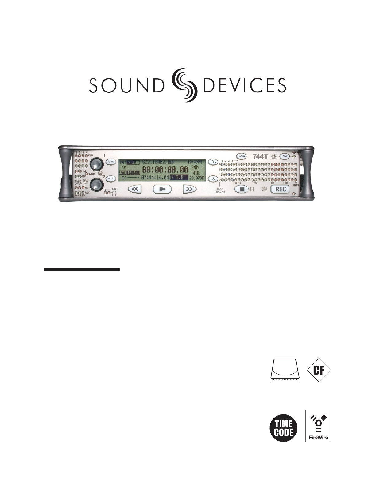
744T
High Resolution Digital Audio Recorder with Time Code
User Guide and Technical Information
rev. 1.04
1.8" HDD
2.5" HDD
Sound Devices, LLC
300 Wengel Drive • Reedsburg, WI • USA
+1 (608) 524-0625 • fax: +1 (608) 524-0655
Toll-Free: (800) 505-0625
www.sounddevices.com
Page 2

Page 3

Table of Contents
Introduction
Table of Contents . . . . . . . . . . . . . . . . . . . . . . . . . . . 1
Quick Start Guide . . . . . . . . . . . . . . . . . . . . . . . . . . . 3
Powering the Unit
Menu Navigation Basics
Connecting Audio Sources
Routing Inputs to Tracks
Recording Parameter Setup
Time Code Setup
Recording
Playback
FireWire File Transfer
Front Panel Descriptions . . . . . . . . . . . . . . . . . . . . . 6
LCD Display Descriptions . . . . . . . . . . . . . . . . . . . . 9
Left Panel Connectors and Controls . . . . . . . . . . 11
Right Panel Connectors and Controls . . . . . . . . . 12
Back Panel Descriptions . . . . . . . . . . . . . . . . . . . . 13
Input Setup and Control . . . . . . . . . . . . . . . . . . . . . 14
Input Source Selection
Analog Inputs 1 and 2
Analog Inputs 3 & 4
Signal Presence and Peak Indicator
Digital Inputs – AES3
Digital Inputs – AES3id (S/PDIF)
Input Delay
Word Clock . . . . . . . . . . . . . . . . . . . . . . . . . . . . . . . 17
Clock Master
Clock Slave
C. Link – Multi-Unit Linking
Input-to-Track Routing . . . . . . . . . . . . . . . . . . . . . . 18
Outputs – Analog and Digital . . . . . . . . . . . . . . . . 20
Master Output Bus
Output Bus 2
Headphone Output . . . . . . . . . . . . . . . . . . . . . . . . . 21
Choosing Headphone Sources
Setting Headphone Source Options
Multi-Function Controller Behavior
Headphone Favorite Selection
Headphone Playback Mode
Warning Tones
Metering . . . . . . . . . . . . . . . . . . . . . . . . . . . . . . . . . . 23
Output Meter
Meter Ballistics
Peak LEDs
Tone Oscillator
LCD Contrast & Backlight, LED Brightness
Sample Rate and Bit Depth . . . . . . . . . . . . . . . . . . 25
Sample Rates
Bit Depths
Time Code . . . . . . . . . . . . . . . . . . . . . . . . . . . . . . . . 26
Frame Rate
Time Code Mode
Jam Menu
User Bits
NTSC Standard Def Video Production
Audio File Formats . . . . . . . . . . . . . . . . . . . . . . . . . 29
WAV / BWF
MP3 – MPEG Layer 3
Recording and Playback . . . . . . . . . . . . . . . . . . . . 29
Recording
Playback
AutoPlay
Storage Medium – Internal Drive . . . . . . . . . . . . . . 31
Formatting
Drive Repair
Drive Type
Drive Life Span
Drive Replacement
Storage Medium – Compact Flash . . . . . . . . . . . . 33
When to Use CF
Formatting
Testing
Drive Repair
Qualifi ed CF Cards
File Naming / Numbering . . . . . . . . . . . . . . . . . . . . 34
Scene Numbers
Take Numbers
File Management and Copying . . . . . . . . . . . . . . . 35
File Finder Navigation
File Directory Screen
Setting/Clearing Flag Bits
Automatic Flag Clearing
Folders
File Time and Date
File Size Maximum
File Copying – Between Internal Drives
File Transfer – FireWire
Powering . . . . . . . . . . . . . . . . . . . . . . . . . . . . . . . . . 39
Lithium Ion Rechargeable Battery
External Powering
Charging
Time Code Master Clock Battery
Firmware Upgrades . . . . . . . . . . . . . . . . . . . . . . . . 41
Version Information
Upgrade Process
Setup Menu Presets . . . . . . . . . . . . . . . . . . . . . . . . 42
Built-In Presets
User Setups
Setup Menu . . . . . . . . . . . . . . . . . . . . . . . . . . . . . . . 44
Specifi cations . . . . . . . . . . . . . . . . . . . . . . . . . . . . . 51
Connector Pin Assignments . . . . . . . . . . . . . . . . . 53
Recording Time Calculation . . . . . . . . . . . . . . . . . 54
Uncompressed Recording Time in Track-Hours
MP3 Compressed Record Time in Hours
Accessories . . . . . . . . . . . . . . . . . . . . . . . . . . . . . . 56
Menu Navigation Shortcuts . . . . . . . . . . . . . . . . . . 57
Glossary of Terms . . . . . . . . . . . . . . . . . . . . . . . . . . 58
Warranty and Technical Support . . . . . . . . . . . . . . 59
Software License . . . . . . . . . . . . . . . . . . . . . . . . . . 60
Notes . . . . . . . . . . . . . . . . . . . . . . . . . . . . . . . . . . . . 61
1
Page 4

744T User Guide and Technical Information
Welcome
Thank you for purchasing the 744T. The super-compact 744T records and plays back audio to and
from its internal hard drive or Compact Flash medium, making fi eld recording simple and fast.
It writes and reads uncompressed PCM audio at 16 or 24 bits with sample rates between 32 kHz
and 192 kHz. Compressed (MP3) audio playback and recording are also supported. The time code
implementation makes the 744T ready for any recording job—from over-the-shoulder to cart-based
production.
The 744T implements a no-compromise audio path that includes Sound Devices’ next generation
microphone preamplifi ers. Designed specifi cally for high bandwidth, high bit rate digital recording,
these preamps set a new standard for frequency response linearity, low distortion performance, and
low noise.
With documentary and ENG mixing engineers in mind, the 744T is very small, while still being feature-rich. No other recorder on the market matches its size and feature set. In addition, its learning
curve is quite short—powerful does not mean complicated. While the 744T is a very capable recorder
by itself, it truly excels when used in conjunction with an outboard audio mixer such as Sound
Devices’ own 442 or 302.
Sound Devices took advantage of the best in professional and consumer electronics technologies to
bring incredible feature depth with ease of use. Its two recording media (hard drive and Compact
Flash) are highly reliable, industry standard, and easily obtainable. The removable, rechargeable battery is a standard Sony-compatible Li-ion camcorder cell. The 744T interconnects with Windows and
Mac OS computers for convenient data transfer and backup.
Copyright Notice and Release
All rights reserved. No part of this publication may be reproduced, stored in a retrieval system, or transmitted in any form or by any
means, electronic, mechanical, photocopying, recording, or otherwise, without the expressed written permission of SOUND DEVICES,
LLC. SOUND DEVICES is not responsible for any use of this information.
SOUND DEVICES, LLC shall not be liable to the purchaser of this product or third parties for damages, losses, costs, or expenses
incurred by purchaser or third parties as a result of: accident, misuse, or abuse of this product or unauthorized modifi cations, repairs, or
alterations to this product, or failure to strictly comply with SOUND DEVICES, LLC’s operating and installation instructions.
Microsoft Windows is registered trademarks of Microsoft Corporation. Macintosh is a registered trademark of Apple Computer. Other
product and company names mentioned herein may be the trademarks of their respective owners.
The sound waves logo is a registered trademark of Sound Devices, LLC.
2
firmware v. 1.04 Features and specifications are subject to change. Visit www.sounddevices.com for the latest documentation.
Page 5
Quick Start Guide
Quick Start Guide
The 744T is an extremely powerful and fl exible portable audio recorder. Before recording, familiarity
with the product is essential. Several settings should be verifi ed or set based on individual recording
needs.
Powering the Unit
1. Apply power to the unit by connecting the (included) removable, rechargeable Li-ion (lithium ion) battery to the back panel battery mount. The metal tabs on the mount line up with the electrical contacts
on the battery. From the factory, the battery may not have a charge, so external DC may be needed for
initial operation and charging. Connect the included AC-to-DC power adapter to the DC input plug to
power and charge the removable Li-on battery.
2. Press and hold the power key (150 ms) to power up the unit. To power down the unit the power button
must be held for one second.
If this is the fi rst time the recorder has been powered, or if it has been without a battery for an extended period, the date and time may need to be set.
Charge the included Li-ion battery for 6 hours prior to initial use.
Menu Navigation Basics
The setup menu provides options for recording, routing, and control parameters. The one layer
menu structure allows for very quick navigation and selection of functions. To enter the setup menu
press the front panel key. Once in the setup menu, the following conventions are shared for
navigating among selections and to select specifi c parameters.
• - enters setup menu
• iitemh - highlighted menu item
• - selects highlighted item or parameter
• - moves up in menu and between menu parameters
• - moves down in menu and between menu parameters
• - exits the selected menu or menu altogether
• The stop key will exit from any menu and cancel any changes. Use it to escape out of the
setup menus.
The right panel Multi-Function Controller (labeled “Select”) is a convenient control to quickly navigate among menu items and item options. Its push-to-select function duplicates the check mark in most
menus.
Connecting Audio Sources
1. Connect audio sources, either analog or digital, to the appropriate input connector.
2. When using either input XLR 1, set the appropriate input level—mic, line, or digital—with the adjacent
slide switch.
3. If mic-level inputs are used on XLR 1 or XLR 2, make certain that phantom power, input limiters, and
high-pass fi lters are activated, as required.
4. When using inputs 3 or 4, set gain levels in the setup menu.
3
Page 6
744T User Guide and Technical Information
Routing Inputs to Tracks
Before recording, inputs must be assigned to tracks. Each of the 744T’s four inputs (1, 2, 3, 4) can
be assigned to any of the four tracks (A, B, C, D). These sixteen possible routing combinations are
shown on the front panel with 16 blue LEDs. Illuminated LEDs indicate input-to-track assignment.
1. Press the input key to cycle through factory routing presets. The 744T has six often-used presets
for quick setup of input-to-track routing combinations. Note the routing combinations on the blue LEDs
with each successive press.
2. If none of the preset routing combinations are suitable, assign a custom routing. Sequential presses of
the input key will eventually cycle to the custom routing option (see Input to Track Routing, pg. 18).
3. Press Exit to leave input routing mode.
The custom input routing menu allows any input to be assigned to any track. Multiple inputs can be assigned to a single track.
Recording Parameter Setup
For most productions, the general recording parameters of sample rate, bit depth, media selection,
and fi le format are changed infrequently. Enter the setup menu to verify recording settings. Sample
rate and bit depth are displayed on the LCD panel.
1. Select the bit depth as needed.
2. Set the sample rate as needed.
3. Select the fi le format for recorded fi les.
4. Select the storage medium (internal hard drive, Compact Flash, or both) for recording.
Time Code Setup
When using a time code workfl ow, proper time code setup is essential. Skip this section if time code
is not being used.
1. Select a time code frame rate appropriate for your project. For fi lm, typical the time code rates are 30 fps
non-drop (US) or 25 fps (EU). For standard defi nition video projects, use either 29.97 or 29.97 non-drop.
For high-defi nition projects, use either 23.976 or 29.97.
2. Select the time code run mode: free run, continuous jam, record run, or 24 hr. run.
3. Use the 744T as the master clock source and jam time code to all other recording devices. This will
assure that every device is using the same time reference. (See Time Code for additional information on
time code setup).
Recording
Now that fi le basics are set, you are ready to begin recording. The 744T is a record-priority box.
Pressing the record key cancels all functions—except fi le operations—and immediately starts recording a new fi le. When record is pressed, the red record LED illuminates to confi rm record mode. The
fi lename in the LCD display shows the currently recorded fi le. Push the stop (150 ms) key to
end recording.
Playback
When recording is stopped, the most recently recorded fi le is immediately available for playback.
Press the key to begin fi le playback from the beginning of the fi le.
To select a fi le for playback:
4
firmware v. 1.04 Features and specifications are subject to change. Visit www.sounddevices.com for the latest documentation.
Page 7
Quick Start Guide
1. Press and hold the key to select the volume for playback. The default playback directory is the
present volume being recorded.
2. Use the Multi-Function Controller, or the arrow soft-keys, to navigate through the fi le directory.
3. Once a fi le is highlighted, press the
play key to begin playback.
When playback has fi nished, the fi lename will begin fl ashing. Use the fast-forward key or
rewind key to step through fi les in the folder, or press the stop key to exit playback mode.
FireWire File Transfer
When connected via FireWire (IEEE-1394a) to a Mac OS or Windows OS computer (see Specifi cations
for computer requirements), the internal hard drive and connected Compact Flash storage mediums are
mounted onto the computer as “letter” accessible drives. Use the appropriate FireWire cable, either
6-pin to 4-pin or 6-pin to 6-pin, for interconnection. Files on the 744T can be treated as if they are local fi les, including renaming fi les, copying, and playing directly from the 744T medium.
In general, it is good practice to copy all needed audio fi les from the 744T to a computer before any processing is performed on the fi les.
To connect the 744T for FireWire transfer:
1. Stop all playback and recording activity.
2. Make certain the 744T battery is fully charged, or connect to external DC.
3. Connect the 744T to the host computer with a FireWire cable.
4. The 744T will enter FireWire transfer, indicated by COMPUTER CONNECTION in the LCD display. All
functions of the 744T are stopped while the 744T is connected to a computer through FireWire.
5. Navigate the drives on the computer and copy all needed audio fi les to the computer.
To avoid possible directory corruption on the 744T internal media, do not interrupt the connection process and always properly dismount the drives from the operating system. On Mac OS platforms, drag the
drive icons to the trash. On Windows platforms, use the “Disconnect External Media” icon in the system
tray.
5
Page 8
744T User Guide and Technical Information
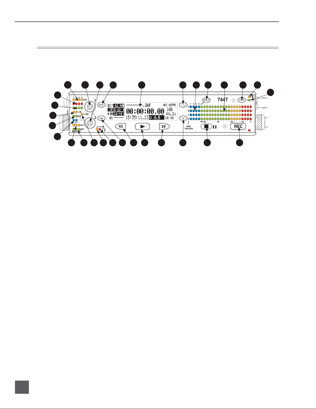
Front Panel Descriptions
All settings of the 744T can be accessed and monitored through the front panel LCD and navigation keys. This allows the unit to be placed in a production bag along with fi eld mixers and wireless
transmitters and receivers.
2 1
29
28
27
26
25
4
1) Digital Input LEDs
Indicates the presence of digital signal
on the respective input. When fl ashing,
indicates that digital input is selected
but no valid digital clock signal is present.
2) Input 1 Gain
Controls the analog gain (input trim) of
the channel 1 input. Normal mic input
range is from 25 dB to 70 dB, low gain
mic range is from 10 dB to 55 dB, line
input range is from −6 dB to 18 dB. For
line-level inputs, this control can be
defeated and gain can be setup menucontrolled. If the LCD display shows
“locked” when the pot is turned, gain
control of the line-level input is menucontrolled. When inputs are linked as a
stereo pair input gain 1 controls the gain
of both inputs.
3) Input 2 Gain
Controls input 2, as in #2 above. When
inputs are linked as a stereo pair input
controls left-to-right balance.
4) MENU Key
Used to access all 744T setup menu
selections. When in menu mode, used to
move up through the menu selections.
Pressing the HDD and MENU keys
simultaneously brings up the time code
jam menu.
5 6
5) LCD Display
6) Tone Oscillator
7) Input-to-Track Matrix LEDs
8) INPUT Select Key
9)
10)
13
10
11
7 8 9 3
15 16 17 18 19
14 20 21 22 23 24
Primary display of 744T status. The
LCD is backlit using the LCD backlight
control (#15).
Tone frequency, tone level, and routing
are controlled in the setup menu. Press
and hold to activate the tone oscillator.
Blue LEDs indicate inputs (1, 2, 3, 4)
enabled for recording to tracks (A, B, C,
D). A solid blue LED indicates an input
is routed to a track. A fl ashing LED during “custom” routing mode shows the
selected input/track combination.
Pressing this key cycles through the six
factory preset input-to-track routing
combinations plus the custom routing
menu. In the custom routing menu any
input can be routed to any track. See
Input-to-Track Routing, page 18.
Level Meter LEDs
Four, 19-segment track level-meters indicate level in dBFS. Metering ballistics
are selected in the setup menu.
Power Key
Press and hold (150 ms) to power up the
744T. Press and hold (1 second) to power
down.
12
6
firmware v. 1.04 Features and specifications are subject to change. Visit www.sounddevices.com for the latest documentation.
Page 9

Hardware Descriptions
11) Charge LED
Indicates the status of the onboard
battery charger. Flashes when external power is connected and battery is
charging; solid when battery is fully
charged.
12) Power LED
Indicates the 744T is powered and available for operation. Flashes when the
removable battery or external DC is in a
low-voltage state.
13) Record Key
Starts recording. The 744T is a recordpriority box, pressing this key activates
recording and discontinues all other
functions, except fi le operations. Pressing key while recording can set a cue
marker or start a new fi le, as selected in
the setup menu.
14) Stop/Pause Key
Press (150 ms) to stop recording.
In playback mode, a single press pauses
playback (play-pause), enabling audio
scrubbing with the FF and REW keys.
Another press of the key enters playstop mode where the FF and REW keys
select fi les for playback from the current
directory. One more press of the key
exits playback mode. In the setup menu
the stop key is also used exit from any
menu, returning to the main display.
17) Play Key
Plays back the fi le displayed on the
LCD. If pressed immediately after
recording is stopped, the most recently
recorded fi le is played back.
18) Rewind Key
Performs reverse (REW) scrubbing
through the played fi le when pressed in
playback and play-pause mode. Playpause indicated by fl ashing A-time on
LCD. Reverse playback rate increases
the longer the key is held. In play-stop
mode (indicated by fl ashing fi lename
on LCD) selects the previous fi le in the
record folder (either daily folder or main
folder).
19) HDD Key
Press to enter the directory listing of the
selected storage medium (either internal
hard drive or CF). Selected medium is
shown in white type. Press-and-hold to
toggle between available mediums. If
only one media is present, press-andhold is disabled.
Pressing simultaneously with MENU
opens the time code jam menu.
20) Headphone Output Peak LED
Indicates overload of the headphone
amplifi er. When lit, the headphone circuit is overloading. Reduce headphone
level.
15) LCD Backlight
Toggles LCD and key backlighting. Hold
down and turn the Multi-Function Controller to vary the brightness of LEDs. In
menu mode, functions as the cancel key.
16) Fast Forward Key
Performs fast-forward (FF) scrubbing
through the played fi le when pressed in
playback and play-pause mode. Playpause indicated by fl ashing A-time on
LCD. Fast forward rate increases the longer the key is held. In play-stop mode
(indicated by fl ashing fi lename on LCD)
selects the next fi le in the record folder
(either daily folder or main folder).
21) LIM LED
Indicates that the microphone input
limiters are activated. This LED does not
show input limiting activity (see descrip-
tor #27, Microphone Input Limiter LEDs).
22) Link LED
Indicates that channels 1 and 2 are
linked as a stereo pair. In link mode the
channel 1 potentiometer controls gain,
channel 2 potentiometer controls leftto-right balance. Inputs can be linked as
either a stereo L/R pair or as an MS pair.
7
Page 10

744T User Guide and Technical Information
23) Media Ready LEDs
Indicates storage media is present and
available to record; IN (internal hard
drive), CF (Compact Flash), EX (external Firewire device) [EX not available in
fi rmware version 1.x]. Flashing indicates
media problem.
24) Media Activity LEDs
Indicates storage media read/write
activity. IN (internal hard drive), CF
(Compact Flash), EX (external Firewire
device) [EX not available in fi rmware ver-
sion 1.x].
25) High-Pass Filter LEDs (mic-level only)
Indicates that the high-pass (low-cut)
fi lter is active for the individual channel.
26) Phantom Power LEDs
Indicates phantom power (48 V) is active for the individual channel.
27) Microphone Input Limiter LEDs
Illuminates orange when limiting is
occurring on the microphone input. If
constantly lit, the microphone input is
being “hit” with too high of a signal.
Turn down the input sensitivity until
limiting occurs infrequently.
28) Input Signal Presence LEDs
Indicates presence of analog or digital
signal and its relative level on each of
the four inputs.
29) Input Peak (Overload) LED
Indicates analog signal is approaching
clipping (–3 dBFS) on each of the four
inputs.
8
firmware v. 1.04 Features and specifications are subject to change. Visit www.sounddevices.com for the latest documentation.
Page 11
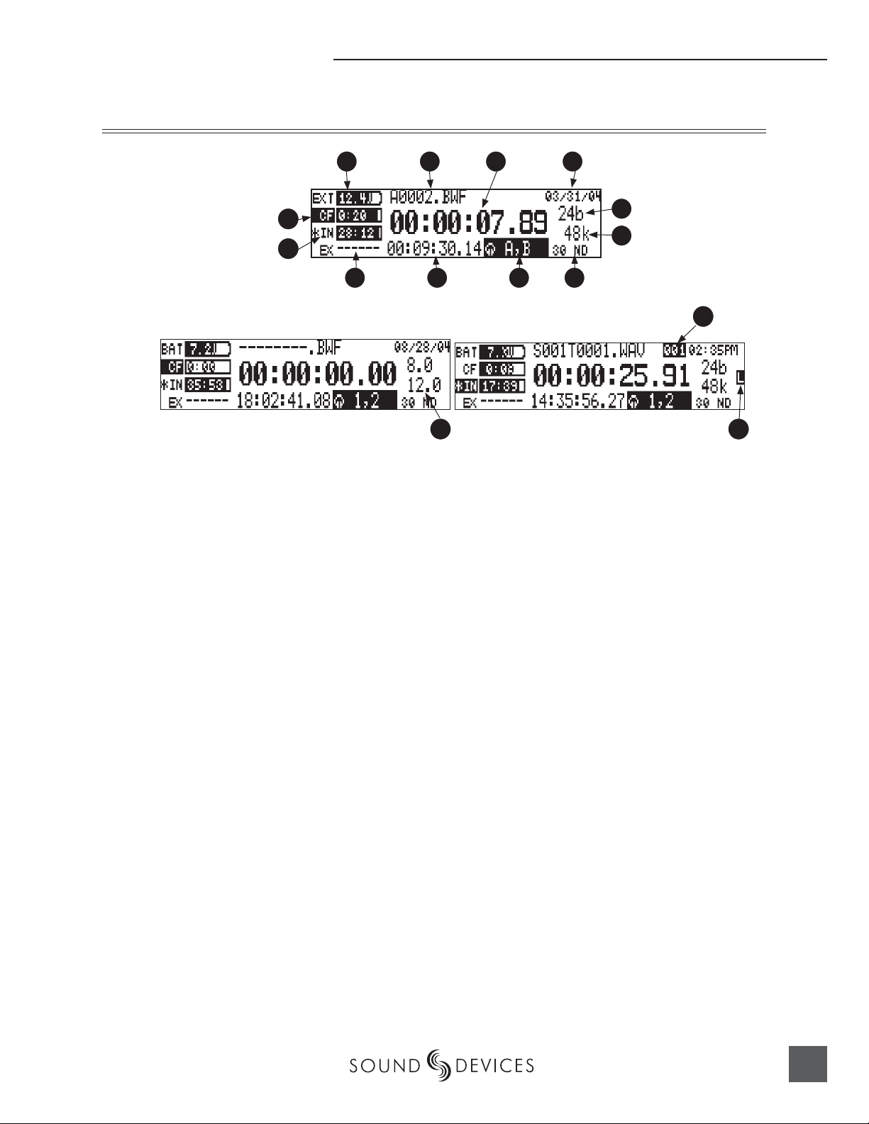
LCD Display Descriptions
Hardware Descriptions
1
12
11
1) Battery Level Indicator
Shows voltage level of removable battery or external power sources. External
power overrides internal power when
present. Graphical bar for relative level
and numeric indicator for precise voltage measurement.
2) File Name Display
Shows fi le name actively being recorded
or played back. In playback-stop mode,
fl ashing fi le name indicates that the fastforward and rewind keys are available
for stepping through fi les in the current
playback directory.
3) Absolute Time (A-time) Display
Shows the elapsed time of the fi le being
recorded or played back. Flashes in
playback pause mode. In this mode the
FF/REW keys will scrub through an
open audio fi le.
4) Time & Date Display
Alternating display between the set date
and time of the 744T. This information is
written as the creation date for generated audio fi les.
9 10
13
4 2 3
5
6
8 7
6) Sample Rate Indicator
Shows the set record sample rate. In
playback, shows the fi le sample rate.
7) Time Code Rate
Shows the set time code frame rate. If a
fi le has time code information embedded, the playback frame rate is indicated. If external time code is connected
and the external rate differs from the
rate set internally, the time code rate will
fl ash.
8) Headphone Source Display
Indicates the source for headphone output. Sources and selection order are user
selectable in the setup menus.
9) Time Code Display
In stop and record, shows the time code
generated by the 744T. In play mode, the
display shows the play fi le’s time code
information (if available). If non-time
code fi les are playing, the display shows
dashes.
14
15
5) Bit Depth Indicator
Shows the set record bit depth. In playback, shows the fi le bit depth.
9
Page 12

744T User Guide and Technical Information
10) External Media Space Status
(space remaining/record ready)
Not available on version 1.x fi rmware. Bar
graph indicates amount of record time
remaining on the external FireWire volume. Numbers show time in hours and
minutes based on the presently selected
number of record tracks, sample frequency, bit rate, and fi le type.
11) Compact Flash Status
(space remaining/record ready)
Bar graph indicates amount of record
time remaining on the Compact Flash
media. Numbers show time in hours
and minutes based on the presently selected number of record tracks, sample
frequency, bit rate, and fi le type.
12) Internal Hard Drive Status
(space remaining/record ready)
Bar graph indicates amount of record
time remaining on the internal hard
drive. Numbers show time in hours and
minutes based on the presently selected
of number of record tracks, sample frequency, bit rate, and fi le type.
15) External Digital Clock Indicator
The 744T is locked to a valid external
digital or word clock source when the L
is in the display.
For all three media types, an asterisk in front
of the media descriptor indicates that the media is selected for record. Highlighted media
descriptor indicates media selected for record
monitoring, playback or fi le directory display.
13) Input 1/2 Level
When control knobs are adjusted,
indicates the gain level in dB for each
analog input gain control. Normal mic
input gain range is from 26 dB to 70 dB,
low gain mic range is from 10 dB to 50
dB, line input range is from −6 dB to 18
dB. “Locked” will be displayed on the
LCD when the pot is turned with digital
inputs, and with line inputs with menu
control.
14) Cue Marker Display
In record mode, indicates when cue
markers are set. Markers set by pressing
the record key (option must be selected
in setup menu). In playback mode, displays cue points numerically as they are
reached in a fi le.
10
firmware v. 1.04 Features and specifications are subject to change. Visit www.sounddevices.com for the latest documentation.
Page 13
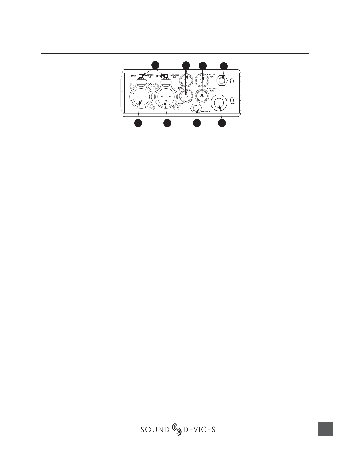
Left Panel Connectors and Controls
Hardware Descriptions
1) XLR Input 1/AES3 Input 1&2
Dual function input connection. Input
type set with switch above. Active-balanced analog microphone- or line-level
input for input 1. Transformer-balanced
two-channel AES3 input (1 and 2).
2) XLR Input 2/AES3 Input 3&4
Dual function input connection. Input
type set with switch above. Active-balanced analog microphone- or line-level
input for input 2. Transformer-balanced
two-channel AES3 input (3 and 4).
1 8 7
3
2
4
5
7) Headphone Volume
Adjusts the headphone volume. NOTE:
the 744T is capable of producing eardamaging levels in headphones.
8) Tape Output
Unbalanced tape (–10 dBv nominal)
output on 3.5 mm TRS stereo connector.
Signal source is identical to the Master
Output Bus. Tip left, ring right, sleeve
ground.
6
3) Mic-Line-AES3 Input Switch
Selects the input level and mode of the
associated XLR input connector.
4) TA3 Channel 3&4 Line Inputs
Active-balanced line-level input connectors. Pin-1 ground, pin-2 (+), pin-3 (−).
5)
TA3 Master (L/R) Analog Outputs
Active-balanced, line-level analog L/R
outputs for the Master Output Bus. Program source and attenuation level are
user selectable. Pin-1 ground, pin-2 (+),
pin-3 (–).
Headphone Output
6)
3.5 mm TRS stereo headphone connector. Can drive headphones from 8 to
1000 ohm impedances to required levels.
Tip left, ring right, sleeve ground.
11
Page 14
744T User Guide and Technical Information
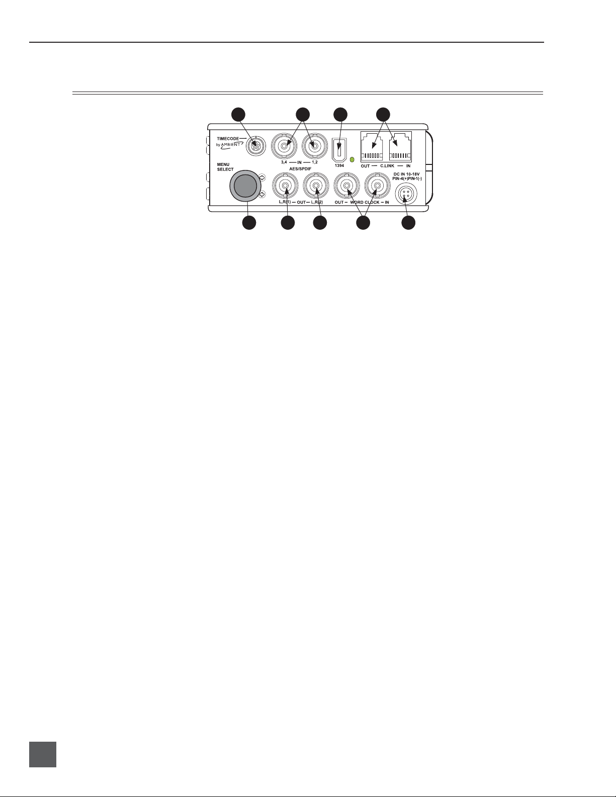
Right Panel Connectors and Controls
1
9 8 7 6 5
1) Time Code Multi-Pin
Time code input and output on 5-pin
LEMO® connector.
2) AES3id Inputs 1/2 and 3/4
Unbalanced digital inputs accept four
channels of either AES3 or S/PDIF on
BNC connectors.
3) FireWire (IEEE-1394) Port
Connection to a computer for access the
internal hard drive and Compact Flash
volumes as mass storage devices. Direct
connection to Mac OS (X-only) and Windows (XP- and 2000-only) computers.
4) C. Link In/Out
RS-232 protocol interface on 6-pin
modular (“RJ-12”) connector for linking
multiple 744T’s together. Word clock,
machine transport, and time code are
carried on C. Link connector.
5)
External DC In
Accepts sources of 10–18 volts DC for
unit powering and removable Li-on
battery charging. The Hirose 4-pin connector is wired pin-1 negative (−), pin-4
positive (+). Pin-2 (−) and pin-3 (+) are
used to charge the removable Li-on battery. DC ground is at the same potential
as chassis and signal ground.
4 3 2
Word Clock Input and Out
6)
Provides clock input and output for the
744T. Word input accepts sample rates
between 32 kHz and 192 kHz. Word
clock out is rate that box is running.
There is no sample rate conversion utility in the 744T.
7) AES3id Master Output Bus
Unbalanced digital output, two-channel,
for the Master Output Bus. Signal source
is menu-selected and is identical to the
Analog Master Output Bus signal.
8) AES3id Output Bus 2
Unbalanced digital output, two-channel,
for Output Bus 2. Signal source is menuselected.
9) Multi-Function Controller
When in the setup menu, the controller
scrolls between menu selections; push
enters selection or enters data. In record
and playback modes, selects headphone
monitor source; pus-h action user selectable.
12
firmware v. 1.04 Features and specifications are subject to change. Visit www.sounddevices.com for the latest documentation.
Page 15
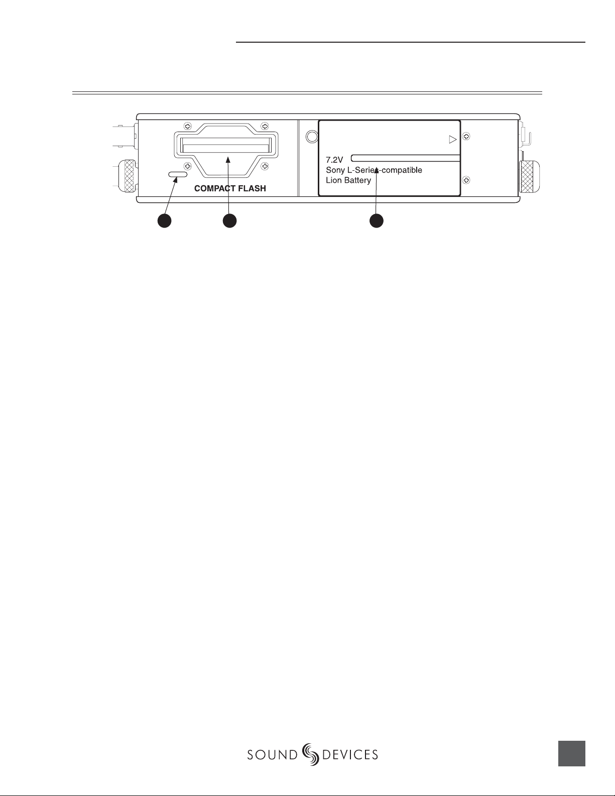
Back Panel Descriptions
Hardware Descriptions
1 32
1) Security Slot
Compatible with the Kensington Security Slot specifi cation. Useful for securing the recorder to a fi xed object with a
compatible computer lock.
2) Compact Flash Slot
Insert Compact Flash medium with the
label-side up. Compatible with Type I,
Type II, and MicroDrives.
3) Battery Mount
Accepts Sony® InfoLithium L- or MSeries batteries. Also accepts batteries
conforming to this mount. Numerous
capacities, from 1500 mAh to 5400 mAh
can be accommodated.
13
Page 16

744T User Guide and Technical Information
Input Setup and Control
The 744T has four inputs and four record tracks. Inputs are selectable among analog or digital sources. Analog inputs 1 and 2 use XLR connectors; analog inputs 3 and 4 use TA3 connections. Digital
inputs can be either AES3 (balanced XLR) or AES3id (BNC) inputs.
One analog pair and one digital pair can be used simultaneously.
Input Source Selection
Input sources are selected in pairs, 1, 2 and 3, 4. Each input pair (1, 2 and 3, 4) accepts analog or digital audio. The XLR input signal is selected with slide switch above the connector. Inputs 3 and 4 are
selected from the setup menu.
Manually selecting the audio source is used to force the inputs to analog while using an AES3 or
AES3id input to lock the 744T to an external sample rate.
Digital sources connected to AES3id BNC inputs override analog signals on the correspond-
ing XLR input. The BNC input signal type is set in the menu settings Input 1,2: Source and
Input 3,4:Source. For most situations the appropriate setting is auto select—the 744T will choose
the input type based on signal present.
The 744T is capable of off-speed sample rates when clocked from either external digital inputs or the
word clock input.
Input sources can be set to “disabled (power save)”. This option shuts down all circuitry associated
with an input pair to save power and prolong battery life. When an input pair is disabled, the digital
input LEDs associated with the pair will slowly fl ash. In playback-only applications, both input pairs
can be shut down to maximize power-effi ciency and extend battery runtime.
Analog Inputs 1 and 2
Analog inputs 1 and 2, on XLR connectors, are the primary connections into the recorder. These
inputs accept balanced or unbalanced mic- or line-level inputs. Gain control for mic inputs 1 and 2 is
adjusted solely by the front panel push knobs. Gain for the line level inputs can be controlled by the
front panel potentiometers or menu settings. Line input gain is available in 0.1 dB steps.
A digital input present on the BNC inputs will override an analog signal present on the XLR inputs unless the input source is set to analog in the setup menu.
In the setup menu, the following functions can be controlled for analog inputs 1 and 2:
Phantom Power (mic- and line-level inputs)
Phantom power (48 volts) can be activated for inputs 1 and 2. When active, phantom is indicated by
front panel LEDs ( ).
14
Phantom power is available for both mic and line level inputs. Using line-level inputs with microphones
is useful in extreme SPL environments such as concert recording. Make certain to deactivate phantom
power when line level output devices are connected that are susceptible to damage from DC.
Shortcut: To toggle phantom power without entering the menus, press and hold the tone key then
press the menu key for channel 1. Channel 2 phantom can be toggled by pressing the tone key then
firmware v. 1.04 Features and specifications are subject to change. Visit www.sounddevices.com for the latest documentation.
Page 17
Input Setup and Control
pressing the HDD key. If the inputs are in line level mode, phantom power will not activate from the
shortcut keys and must be activated from the menus.
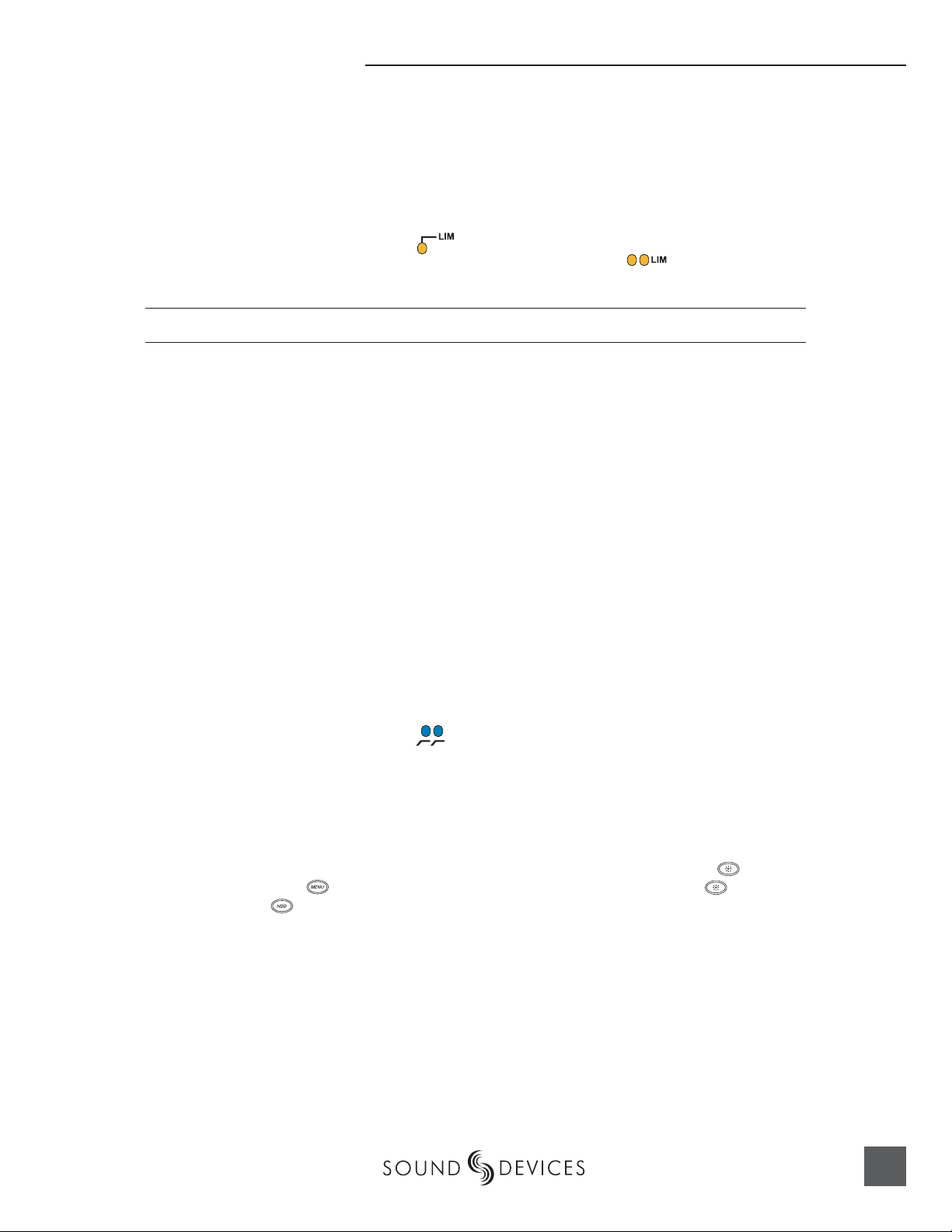
Input Limiters (mic-level only)
Microphone inputs 1 and 2 each have a limiter circuit designed to prevent input overload. In normal operation, with proper gain settings, the limiters should rarely engage. When activated, these
limiters will prevent unusually high input signal levels from clipping the analog input stage of
the preamp. The front panel LIM LED ( ) shows that the limiter is engaged. Limiter activity is
indicated by additional front panel LEDs, one for each input channel ( ). The input limiters are
active only with mic-level inputs. The limiters are engaged by (factory) default.
When limiters are engaged, audio on channels 1 and 2 is limited to −6 dBFS.
Microphone-Level Control
Microphone gain is controlled by the front panel recessed knobs. The gain control adjusts an analog
gain stage and is identical to the input trim on a mixing console or stand-alone microphone preamplifi er.
Line-Level Gain Control
When in line-level position, the gain for inputs 1 and 2 is controlled by the front panel recessed
knobs or by a menu sensitivity setting. When set for front panel control, the user menu selection for
input 1 and 2 line input sensitivity are lined out and not accessible.
Input Linking (mic- and line-level)
Analog inputs 1 and 2 can be linked as a stereo pair. When linked, the channel 1 front panel potentiometer controls the signal level of both inputs, and the channel 2 pot controls the left-to-right balance
of the pair. When the inputs are linked, their peak limiters are linked, as well.
When set as an MS pair, the inputs gain and balance for the pair work the same as stereo linking.
There is no stereo width control as an MS pair since gain is adjusted.
High-Pass Filters (microphone-level only)
The high pass fi lters on the microphone inputs use a combination of analog and digital fi lters to reduce sensitivity to low frequency signals. When the high-pass is engaged on an input, its front-panel
LED illuminates to indicate it is active ( ). The fi rst pole of the high-pass circuit is an analog fi lter
at 40 Hz, 6 dB per octave and is part of the microphone preamplifi er circuit. Additional poles of
high-pass fi ltering are done in DSP.
Several frequency and slope combinations are selectable, including corner frequencies of 40, 80, 160,
or 240 Hz, and fi lter slopes of 12 dB, 18 dB, or 24 dB per octave. The high-pass is selected in the setup
menu for each input independently.
Shortcut: The fi lters can be toggled with a two-key combination. Press and hold the LCD back-
light key and press the menu key for channel 1 high-pass. Press and hold the LCD backlight
key and press the HDD key to toggle channel 2 high-pass.
Gain Range (microphone-level only)
The microphone inputs operate in two gain ranges, normal and low. The normal range is from 25 dB
to 70 dB of gain. The low range is from 10 dB to 55 dB. The low range is useful for high SPL recording environments.
Analog Inputs 3 & 4
Appearing on TA3 connectors, inputs 3 and 4 accept balanced or unbalanced line-level signals. These
inputs have few controls and are typically fed from the output of a mixer or preamplifi er.
15
Page 18
744T User Guide and Technical Information
Gain (sensitivity) for inputs 3 & 4 is controlled in the setup menu. Gain resolution is in 0.1 dB increments.
Analog Line Input Sensitivity
Input level sensitivity for the line-level inputs is adjustable, in 0.1 dB steps, from -6 dBu to +18 dBu.
While adjusting the input sensitivity, the meters will show the relative signal level present on each
input on the meters.
While channel 1 and 2 levels can be controlled by either the menu settings or the front panel pots,
channels 3 and 4 are adjusted only in the setup menu.
Signal Presence and Peak Indicator
The four signal presence and peak indicators show audio activity before input-to-track routing. Input signal presence LED’s illuminate when a -50 dBFS or greater signal is present. Input signal
peak LEDs illuminate when signal levels reach -3 dBFS or greater.
Digital Inputs – AES3
The 744T accepts AES3 (AES/EBU) balanced digital at the XLR connectors. Digital inputs are in
pairs—AES3 signals on XLR-1 appear at inputs 1 and 2, AES3 signals input to XLR-2 appear at inputs 3 and 4. To use the AES3 inputs, the input mode-select switch must be set to AES/EBU.
The front panel digital input LEDs will illuminate when digital input is selected for the in-
dicated track(s). If the LED is fl ashing, digital input is selected but a no valid digital clock is received.
Digital Inputs – AES3id (S/PDIF)
The 744T accepts AES3id and S/PDIF unbalanced digital signals at the BNC connectors. The 744T
will auto detect the type of digital signal and adjust accordingly. Input signals are in pairs, signals on
BNC 1 appear at inputs 1 and 2, signals on BNC 2 appear at inputs 3 and 4.
AES3id inputs override analog signals present at the XLR inputs. To input analog audio while using
the AES3id signal as a digital clock source, you must select analog in the input source menu selection
for the appropriate inputs.
When a digital signal is present, the 744T will lock its sample rate to the source frequency. This is
indicated by a highlighted block on the main LCD display to the right of the bit depth and sample
rate indicators. Recording bit depth is not affected by the external digital source.
If you are locking the 744T to an external digital signal, be certain the source is stable. Loss of the
digital signal will cause the 744T to revert to its internally set sample rate, even while recording. The
portion of the fi le recorded after the loss of signal may not play back properly. Once recording has
begun, unused digital inputs are muted, digital signals that appear on them after the record key has
been pressed will not be recorded or affect the sample rate of the 744T.
The 744T will clock itself to the fi rst digital signal presented to it. If the 744T detects a digital signal on
the BNC inputs and locks to that signal, a digital signal applied to the XLR input will be ignored until
the fi rst digital signal is removed.
16
Input Delay
A digital delay is selectable on each channel of the 744T. Delay time per input in one microsecond
(µS) steps. 1,000 microseconds equals 1 millisecond (ms). The Multi-Function Controller and menu
firmware v. 1.04 Features and specifications are subject to change. Visit www.sounddevices.com for the latest documentation.
Page 19
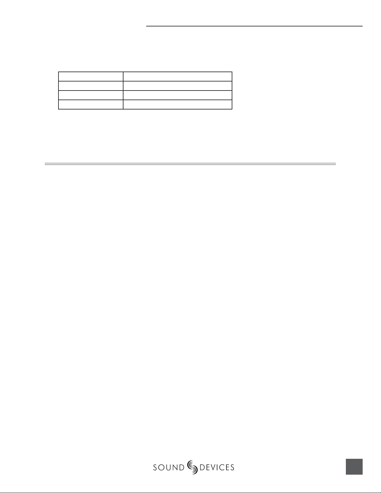
arrows are accelerated. The more you press or spin, the faster the delay setting will increment or
decrement. Delay is not set until enter is pressed. The amount of delay available is dependent on the
sampling frequency in use.
Sample Frequency Maximum Amount of Delay Available (per input)
32, 44.1, 48, 48.048 kHz 30,000 µS
88.2, 96, 96.096 kHz 15,000 µS
176.4, 192 kHz 7,500 µS
Input delay can be useful for time aligning input signals from differing sources. For example, digital
wireless mics that have a processing delay in their outputs or recording a direct PA board feed as
well as a live mic in the front of house space.
Word Clock
Stable word clock is fundamental to a high quality audio signal. The 744T uses a rock-stable time
code crystal to generate its internal word clock frequencies. The 744T can clock external devices from
its word clock and accept external clock sources for recording.
Word Clock
The 744T can be used as a master word clock source or it can lock to external word clock during
recording. The 744T disregards external clock, both AES and word clock, during playback.
Clock Master
When sending digital audio to several devices, one unit is designated as the word clock master and
the others should be slaves. Generally, the device with the analog-to-digital converter is designated
as the word clock master.
The 744T can function as an A/D converter and can be used as the master word clock source. Slaved
devices will derive their word clock timing from either their digital audio inputs, S/PDIF or AES/
EBU, or through their word clock input connection. As a word clock master the 744T generates word
clock whether or not audio is sent.
Clock Slave
When using an external digital preamplifi er connected to the 744T inputs, the recorder can derive its
clock signal from the AES (S/PDIF) stream (it will slave to the external device), or the external device
can be slaved from the 744T (if the external device has word clock input). If, for example, you are using a wireless receiver with a digital output, it may not have an external word clock input, and will
be the word clock master.
If digital audio is connected to the 744T from more than one digital device, you must word clock the
sources to the same clock, otherwise variations between the sources will render their signals unusable.
If the 744T is slaved to external word clock, be certain that the source is stable. Loss of the word clock
signal during recording can cause the 744T to revert back to its internally set sampling frequency.
If this occurs, the portion of the fi le recorded after the loss of word clock may not play back at the
proper speed. For reliability, we recommend you set the 744T to the same sample frequency as the
word clock source. Loss of the word clock signal in this case will most likely cause a glitch in the fi le,
but the fi le will still be usable.
17
Page 20
744T User Guide and Technical Information
To avoid digital loops, when using the word clock and digital input signals, you must make the 744T the
word clock follower of the digital source.
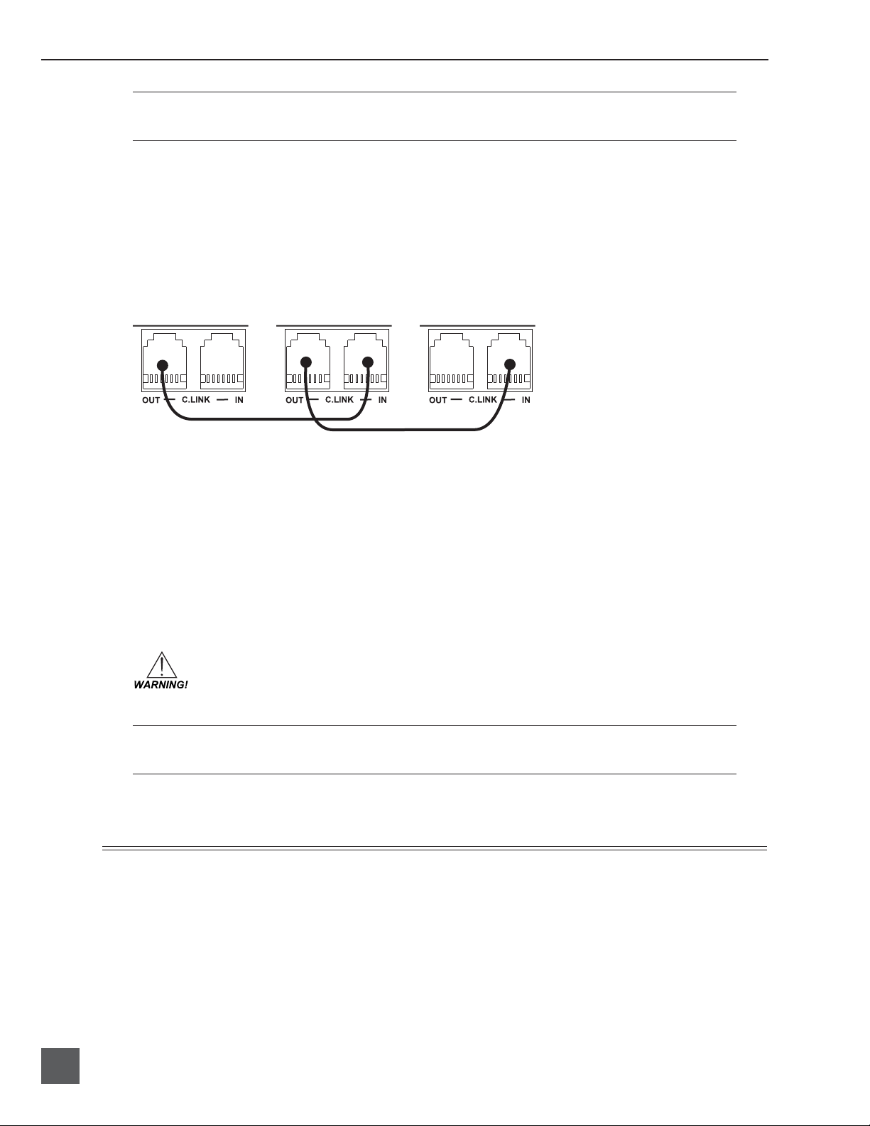
C. Link – Multi-Unit Linking
The proprietary C. Link protocol (control link) allows multiple 744T’s and 722 recorders to be connected and word clocked together. When linked, the 744T units have a master/slave relationship.
When the master recorder is put into record, the slave unit will roll as well. Multiple units can be
daisy-chained together to record many tracks. The C. Link protocol links carries the following data:
• word clock
• time code information
• RS-232 machine transport data
master
unit
To link units:
1. Connect multiple units as shown in the illustration above.
2. Set all linked recorders to the same sample rate, bit depth, fi le format, and time code frame rate (if
used). This will ensure that all fi les generated are compatible.
3. If time code is being used, set slave units to continuous jam mode so that they will follow the master
recorder’s time code generator.
4. Set scene and take numbers on all linked recorders to the same starting fi le name. There is no fi le name
synchronization with multiple unit linking.
When linked, record start and stop on slave units will not affect units “above” it in the
linked chain. This makes it possible for units to get out of synchronization if a unit other
than the master is set to record or stop. Using the master unit will assure that all machines
begin and end recording together.
The C. Link jack is a proprietary RS-232 port. Under no circumstances should analog or digital telephone
lines be connected to either jack. Serious damage could result.
slave
unit
slave
unit
Input-to-Track Routing
18
The 744T uses a simple, yet powerful routing scheme. The microprocessor-controlled matrix allows
any input to be routed to any track. Multiple inputs can be routed to a single track to create monomixed recordings.
The 4 by 4 blue LED matrix makes it easy to check your current routing at a glance. A solid blue LED
indicates an input is assigned to a record track.
firmware v. 1.04 Features and specifications are subject to change. Visit www.sounddevices.com for the latest documentation.
Page 21

Input-to-Track Routing
any combination of
the four inputs can
be routed to any of
the four tracks
Regardless of which tracks are assigned for recording, monophonic fi le numbering always starts with 1,
i.e., if only track D is selected for recording in a monophonic .WAV fi le, the resulting fi lename will have a
_1 suffi x, not _4. Polyphonic fi les will play back the recorded track starting from track A, i.e., if a poly fi le
is recorded on tracks B and D, playback will occur on tracks A and B.
Use the Input:Routing selection in the menu to enter input select mode. Alternatively, press the
input key to cycle through the six preset input routing combinations.
The last selection in the list is Custom Route. Press the EDIT soft key to enter custom routing mode.
Custom routing allows any input to be assigned to any record track. When assigning customer routing, active input and track combination are displayed in white text. The four inputs are shown on the
left; the four record tracks are shown on the right.
To assign custom input routing:
1. Press the input key until Input Routing is displayed in the LCD display.
arrow indicates highlighted input is assigned
to highlighted track
select to exit menu and
apply selected routing
selet to move up
and down menu
2. Press the EDIT soft button (
3. Using either the Multi-Function Controller or the up and down arrows, navigate to desired input-to-
track combinations.
4. When a chosen pairing is highlighted press either the ASSIGN soft key or the Multi-Function Controller
to assign the combination. Assigned tracks are noted on the screen by the addition of an arrow pointing
to the record track. The LED routing matrix will also show a fl ashing blue LED for the currently selected
input-to-track combination.
5. Once a track is assigned move to the next input-to-track combination desired.
6. To remove an input-to-track combination assignment, navigate that combination and press the
UNASSIGN soft key.
7. Exit and complete the assignment by pressing the check mark soft key.
) and scroll to the appropriate input screen.
select to remove
input assignment
The input routing menu will always exit to the main screen whether entered from the input key or the
menu selection.
19
Page 22

744T User Guide and Technical Information
Outputs – Analog and Digital
The 744T has two discrete output buses , the Master Output Bus and Output Bus 2. Each of these
two-channel buses are assigned their audio sources independently, enabling the 744T to feed multiple sources with unique two-channel program.
The chart below shows the audio sources available for the Master Output Bus and for Output Bus 2.
The audio sources for each output bus are selected in the setup menu.
Master Output
Bus and Output
Bus 2 Sources
Stereo input pairs. Input 1 (and 3) is assigned to left output; input 2 (and 4) is assigned to right
Inputs 1,2
Inputs 3,4
Tr a ck s A,B
Tr a ck s C,D
Monitor A,B
Monitor C,D
output.
When inputs are selected as the source for the outputs, the state of recording or playback
activity has no effect on the output signal. This allow uninterrupted audio at the outputs.
Stereo track pairs. Track 1 (and 3) are assigned to the left output; track 2 (and 4) is assigned to
right output. On playback, will play as track monitor.
Stereo monitoring of playback (post-record) track pairs. Highlighted media is source of monitor
program. Track 1 (and 3) is assigned to left output; track 2 (and 4) is assigned to right output. When
not playing or recording there is no output. There is significant delay in the monitor signal while
recording due to the record buffer topology.
Description
Master Output Bus
Audio signals routed to the Master Output Bus are sent to three output connections:
• analog line out, 2 x TA3, two-channel
• analog tape out, 3.5 mm TRS, two-channel
• digital 1, AES3id, BNC connection, two-channel
Analog Line Out L, R
The analog line outputs are active-balanced line-level signals on Switchcraft TA3M locking connectors. The output level is a nominally +4 dBu at −20 dBFS. The level of the line output can be attenuated in the setup menu by up to 40 dB in 1 dB increments.
Analog Tape Output
The tape output connection is stereo, unbalanced consumer output level (–10 dBV) on a TRS 3.5 mm
connector. Output attenuation does not affect this output level.
Digital AES3id Output
The unbalanced AES3id output is directly compatible with most S/PDIF inputs. Attenuation to the
Master Output Bus affects both analog and digital signals.
Output Bus 2
Just as with the Master Output Bus, Output Bus 2 can be assigned signal sources from inputs or
tracks. Sources assigned to Output Bus 2 are exclusive and do not affect the assignments to the Master Output Bus or headphone assignments. The same signal sources available for the Master Output
Bus are available for Output Bus 2 (see chart above).
20
Digital AES3id Output 2
Output Bus 2 appears solely on the AES3id BNC output connector. There is no analog output connections for Output Bus 2. The unbalanced AES3id output is directly compatible with most S/PDIF
inputs. The maximum output level is 0 dBFS and can be attenuated in the setup menu in 1 dB increments by 40 dB.
firmware v. 1.04 Features and specifications are subject to change. Visit www.sounddevices.com for the latest documentation.
Page 23

Headphone Output
Headphone Output
The 744T headphone output is a fl exible tool for monitoring audio in the fi eld. The 744T allows the
user to monitor inputs, tracks, or post-record tracks. The headphone output is independent of the
Master Output Bus and Output Bus 2—audio sources can be routed to headphones independent of
routing assignments to output buses.
The 744T is capable of driving headphones to extremely high sound pressure levels. Hearing experts
advise against exposure to high sound pressure levels for extended periods.
Choosing Headphone Sources
The headphone source display on the main LCD screen ( ) shows the audio sources sent
to headphones. The 744T comes from the factory with 10 preset headphone audio source selections
available on the Multi Function Controller. These selections include inputs, tracks and track monitors. Turn the Multi-Function Controller on the right panel when at the main LCD screen to select
among the available headphone monitoring sources.
Track Monitor
The 744T can monitor recorded audio from the internal hard drive or Compact Flash while recording. To monitor recorded tracks, select one of the track modes with an “m” following the track
designations. Because of the record buffering of the 744T, a delay of up to 12 seconds can be expected
before recorded audio appears at the output. The 744T will play back recorded audio from the media
highlighted in the LCD panel (see File Management and Copying for more information on selecting
and highlighting recording medium).
Setting Headphone Source Options
In addition to the 10 preset headphone routings, a total of 20 available “slots” can be fi lled in a user
defi ned order. Headphone monitoring sources can be set from various combinations of inputs,
tracks, and post-record tracks, including stereo and MS decoding. The order of headphone selections
is user selectable. Available audio sources for headphone monitoring include:
HP Sources Description
Inputs 1,2
Inputs 3,4
Tr a ck s A,B
Tr a ck s C,D
Monitor A,B
Monitor C,D
Input 1
Input 2
Input 3
Input 4
Tr a ck A
Tr a ck B
Tr a ck C
Tr a ck D
Monitor Am
Monitor Bm
Monitor Cm
Monitor Dm
Inputs 1,2 MS
Inputs 3,4 MS
Stereo monitoring of input pairs. Inputs 1 and 3 are assigned to left headphone output; inputs 2 and
4 are assigned to right headphone output.
Stereo monitoring of track pairs. Tracks 1 and 3 are assigned to left headphone output; tracks 2 and
4 are assigned to right headphone output. Upon playback, will play as track monitor.
Stereo monitoring of playback (post-record) track pairs. Tracks 1 and 3 are assigned to left headphone output; tracks 2 and 4 are assigned to right headphone output.
Solo monitoring of selected input. This signal is sent to both sides of the headphones.
Solo monitoring of selected track. This signal is sent to both sides of the headphones. Upon playback, will play as track monitor.
Solo monitoring of playback (post-record) track. Highlighted media is source of monitor program.
This signal is sent to both sides of the headphones. When not in playback, headphones have no
program.
Stereo monitoring of discrete M (mid) and S (side) input pairs. Highlighted media is source of monitor program.
21
Page 24

744T User Guide and Technical Information
HP Sources Description
Tr a ck s A,B MS
Tr a ck s C,D MS
Monitor A,B MSm
Monitor C,D MSm
When tracks (A, B, C, or D) are assigned to headphones, audio assigned to the tracks appear in headphones during recording whereas the recorded track audio appear in headphones during playback.
To set the available headphone source options for headphone monitoring enter the HP: Monitor
modes menu. Once you enter the Monitor Modes menu you will immediately be in slot-1. Rotate the
Multi-Function Controller to select the source you wish to appear fi rst in your Headphone moni-
tor list. Once the chosen source appears, press the Multi-Function Controller or the soft key ENTER
(tone) key to move to the next slot. Continue down the list to select the source for each slot in the list.
Once all sources have been chosen, press (done). This will exit the headphone monitor mode setup.
You can exit the selection process by pressing the stop or cancel (backlight) key at any time.
If you press (done) in the fi rst headphon slot, the 744T will select a single option (Tracks A, B) for headphone monitoring. The 10 factory presets will be erased.
Stereo monitoring of discrete M (mid) and S (side) track pairs. Highlighted media is source of monitor program. Upon playback will function as MS track monitor.
Stereo monitoring of playback (post-record) discrete M (mid) and S (side) track pairs. Highlighted
media is source of monitor program. When not in playback, headphones have no program.
Multi-Function Controller Behavior
The action of the Multi-Function Controller during recording and playback is set from among the
four available options:
• Disabled: pushing the controller has no effect.
• Selects Favorite Mode: places the headphone source into the mode selected in the HP Favorite
menu.
• Headphones to C/D meters: shows the level of the headphone output on the C/D track me-
ters.
• Playback/Monitor Drive Select: pushing the controller toggles between the available media to
select the drive available for playback and track monitor while recording.
Headphone Favorite Selection
If “Selects Favorite Mode” (above) is selected, a press of the Multi-Function Controller selects the
assigned “Headphone Favorite” audio source. This feature is helpful to quickly return to a selected
headphone monitoring source while recording or playing. All possible headphone sources are available to choose as the Headphone Favorite. The Headphone Favorite is selected in setup menu #60.
Headphone Playback Mode
The user may select a headphone source that will automatically be selected by the 744T upon playback. All headphone source selections are available for Headphone Playback Mode, as well as “No
Change”, which leaves the headphone source set to the currently selected mode. Headphone Playback Mode is controlled in setup menu #61.
22
Warning Tones
The 744T can generate an audible beep, or warning “bell”, in the headphones when an error has occurred. The specifi c error will be reported on the LCD. The output level of the warning bell is menuselectable from off to 0 dBFS in setup menu #62.
firmware v. 1.04 Features and specifications are subject to change. Visit www.sounddevices.com for the latest documentation.
Page 25

Metering
The 744T features a 76 LED (4 x 19) output meter. The DSP-controlled output meter provides a selection of ballistics and lighting intensities. In addition, peak indicators on input channels show clipping activity.
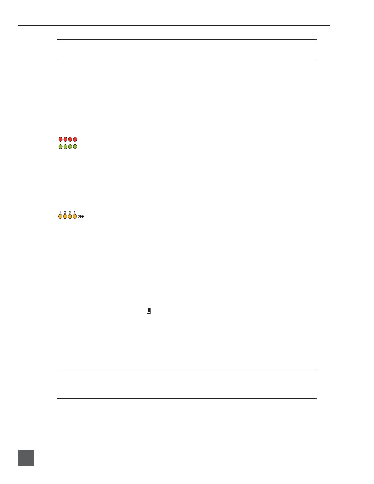
Output Meter
0 dBFS track LEDs are programmable
as peak LEDs
(0 dBFS to −20 dBFS)
The meter uses energy effi cient LEDs which are viewable in full sunlight. The 744T output meter is
unaffected by shock or extremes in temperature and humidity. Meter ballistics are setup menu selectable among VU, Peak, Peak-Hold, VU + Peak and VU + PeakHold.
The meter uses a non-linear metering scale which increases meter resolution in the most important
part of the scale. From −50 to −40 dBFS, each LED segment equals approximately 10 dB. From −40 to
−12 dBFS, each segment equals 2 dB. From −12 to 0 dBFS each segment equals 4 dB.
Metering
Meter Ballistics
The output meter can be set to display any of fi ve types of meter ballistics: VU, Peak, Peak-hold,
a combination of VU and Peak, and a combination of VU with Peak-hold. The meter ballistics are
selected in the setup menu.
VU - (Volume Units)
Ballistics correspond closely to how the human ear perceives loudness and provides a good visual
indication of how loud a signal will be. In VU mode, the attack and decay of the meter signal is
300 mS. While giving a very good visual indication of perceived loudness, VU meters gives poor
information on actual signal peaks and are virtually useless for tracking to the 744T. In VU mode, the
front panel meter labeling is in volume units.
Peak
Peak-reading ballistics correspond to actual signal maximums, but don’t necessarily correspond to
perceived signal loudness. A peak meter has a near-instantaneous attack to display maximum signal
amplitude and a slow decay to allow the user to see them. Peak metering is essential for digital recording, since signal overload can cause immediate distortion. The peak meters front panel markings
are calibrated in dBFS, decibels relative to full scale digital signal.
Peak Hold
Essentially the same as Peak metering where the peak level indication will hold for the peak level
indication for several seconds. Peak-hold indicators are useful for metering in applications when an
overload condition is unacceptable.
Peak/VU
The meter can simultaneously display VU and Peak level information. In this mode the perceived
loudness (VU) is displayed on a bar graph, and the Peak signal on a dot above the VU. With this
23
Page 26

744T User Guide and Technical Information
combination the user gets the best of both VU and Peak metering by seeing both the “loudness” of
the signal and the peaks at the same time. Peak/VU is the factory default.
Peak Hold/VU
Similar to VU/Peak mode, this mode holds the peak level indication for several seconds before
releasing. Peak Hold indicators are useful for metering in applications when an overload condition is
unacceptable.
Peak LEDs
input peak LEDs
input signal present LEDs
headphone peak LED
In addition to the main LED output meter, peak LEDs show input peaks, track peaks, and headphone peaks.
Input Peak
The 744T has a peak LED associated with each input. These LEDs illuminate when input signals
reach the user-selected signal threshold.
Track Peak
The 0 dBFS LED on each track can also function as a track peak indicator. The user can select a signal
threshold above which the 0 dB LED will fl ash.
Headphone Peak
Like the channel peak LEDs, the headphone circuit has an indicator for peak overload. This LED is
useful, since headphones can often overload before the recorder overloads. Monitoring without a
visual indication of headphone clipping may mislead the operator into thinking that the output or
return tracks are distorting.
Tone Oscillator
The tone oscillator level and frequency are user selectable. Reference level is adjustable over a range
of −40 to 0 dBFS. Reference tone frequency is adjustable from 100 to 10,000 Hz. Standard tone levels
vary according to the practices and needs of production and post-production, but are generally in
the -20 to −12 dBFS range. Select a range that is appropriate for your project one that will allow suffi cient headroom.
The tone oscillator is activated by pressing the front panel key. Tone is sent to all active tracks
while the key is depressed.
LCD Contrast & Backlight, LED Brightness
24
LCD
LCD contrast is setup menu controlled. From the factory the contrast is set to 20%, suitable for most
viewing conditions. Contrast can be increased or decreased.
The front panel key toggles the LCD and key backlight. Backlighting is suitable for low- and
no-light recording.
firmware v. 1.04 Features and specifications are subject to change. Visit www.sounddevices.com for the latest documentation.
Page 27

Sample and Bit Rate
LED brightness is continuously adjustable from low to high brightness. Hold down the key
and turn the Multi-Function Controller to change brightness levels. All LED’s are adjusted. In stealth
mode (setup menu selected) the LEDs are toggled on and off with the brightness key.
Sample Rate and Bit Depth
When recording to BWF (and WAV fi les) the 744T generates uncompressed, PCM audio fi les at userselected sample rates and bit depths. The 744T LCD indicates available recording time based on the
sample rate, bit depth, and number of tracks set for recording. See the Calculating Recording Time later
in this guide to estimate record time.
Sample Rates
When a sample rate is selected for recording, all tracks are recorded at the selected sample rate.
Sample rates are selected among common rates from 32 kHz to 192 kHz. Additionally, non-standard
sample rates can be applied when the 744T is word clocked from an external source.
Sampling Frequency = Available Audio Bandwidth
The sampling frequency is expressed in samples per second (in hertz) and defi nes the number of
times in a second that the analog audio signal has been measured. Sampling frequency determines
the audio bandwidth, or frequency response, that can be represented by the digital signal. A quick
estimate of the maximum bandwidth capable of being represented at a given sample rate is maximum analog frequency = sampling frequency/2. Higher sampling frequencies allow for wider audio
bandwidth.
Bit Depths
The 744T records at bit depths of either 16 or 24 bit. 24 bit recording provides greater dynamic range
and addition headroom for signal peaks relative to 16 bit recordings. 24 bit acquisition is a signifi cant
benefi t for fi eld production audio tracks.
Bit Depth = Available Dynamic Range
Bit depth defi nes the digital “word length” used to represent a given sample. Bit depth correlates to
the maximum dynamic range that can be represented by the digital signal. Larger bit depths theoretically yield more dynamic range. A quick estimate of maximum dynamic range capable of being
represented by a given word length is dynamic range ~= no. of bits x 6 dB. Bit depth is an exponential measure (exponent of 2), so as bit depth increases, the amount of data it represents increases
exponentially. The majority of fi eld recording is done with 16-bit audio, therefore, each sample is represented by a digital word of 2^16 (65,536) possible values. 24-bit audio has a word length of 2^24
(16.7 million) possible values per sample.
The 744T has 24 bit analog-to-digital converters. To obtain 16 bit recording the 744T can be set to
dither 24 bit digital signals to 16 bit. The 744T uses a proprietary pseudo-random dither routine for
accurate bit rate reduction. Dither can be defeated in the user menu. Without dither 24 bit audio is
truncated to 16 bit, meaning the least signifi cant 8 bits are discarded.
25
Page 28

744T User Guide and Technical Information
Once a fi le is recorded its sample rate and bit depth can not be changed in the recorder. The 744T can not
perform sample rate conversion or bit depth changes. File conversion must be done in another environment, such as an audio workstation. Alternatively, a real-time analog transfer is often performed instead
of sample rate conversion.
Time Code
The 744T uses time code circuitry developed by Ambient Recording GmbH, a leading developer of
stable, portable time code products (visit Ambient on the web at www.ambientaudio.com). Clock
stability and continuity are critical aspects of the 744T time code implementation. Its temperaturecontrolled (compensated) crystal oscillator ensures rock solid TC stability and accuracy (< 0.2 ppm
when tuned with an Ambient Mastercontroller).
The 744T holds accurate time code for up 8 hours between battery changes using its internal, rechargeable AA NiMH time code cell. This time code battery is charged from internal or external
power whenever the 744T is powered up.
Non-linear fi le-based recordings place a single time code number in the data header of an AES31
(.BWF) fi le. The 744T generates SMPTE time code from this number and extrapolates it based on the
time code frame rate for playback.
Frame Rate
Time code frame rate is selected in the Timecode:Framerate menu.
The 744T supports the most common production time code rates:
• 23.976 – used with Sony high defi nition video cameras
• 24 – to sync audio to fi lm where no transfer to NTSC video is expected
• 25 – to sync sound to PAL video
• 29.97 – to sync sound to NTSC video shot in non-drop frame mode and Panasonic high defi ni-
tion cameras
• 29.97DF - to sync sound to NTSC video shot in drop frame mode
• 30 – to sync sound to fi lm where transfer to NTSC video is expected
• 30DF – to sync sound to fi lm for transfer to NTSC video in drop-frame mode 30 fps
Time Code Mode
The 744T has fi ve time code modes: off, Free Run, Record Run, Continuous Jam, and 24 Hour Run.
Off:
The time code generator is disabled. The front panel time code display is blank.
Free Run:
The internal time code generator runs continuously without regard to the record mode. Time code
value defaults to 00:00:00:00, a user entered value, or the value last in the internal generator. The user
can jam any start value into the generator from the jam menu.
26
Record Run
The time code generator runs only when the 744T is recording. Time code in this mode defaults to
firmware v. 1.04 Features and specifications are subject to change. Visit www.sounddevices.com for the latest documentation.
Page 29

00:00:00:00 at power-up. When switching to record run from another mode, the internal generator
will stop at the last number generated. A user-defi ned value can be jammed into the internal generator from the jam menu.
Continuous Jam:
The onboard time code generator will re-jam from external time code whenever time code is connected to the TC input. Similar to free run mode, the generator runs continuously without regard to
record mode. For a jam to occur, the time code signal must be disconnected and re-connected to the
time code input. Continuous jam is useful when slaving additional recorders to a master recorder.
Slaves should be set to continuous jam to follow the master time code device.
24 Hour Run
Identical to free run with the exception that the generator will automatically jam itself from the
time-of-day clock on power-up. The generator will also re-jam if the time-of-day clock is reset. Once
jammed, the generator will run continuously from the time code clock, not the time-of-day clock.
If the time-of-day clock is reset during the production day, the time code generator value will change. You
must re-jam all time code devices to ensure proper synchronization.
Jam Menu
incoming received
timecode or zero value
Time Code
press to jam
menu selection
744T current timecode value
Time code setup is done from the jam menu, Timecode Jam Menu. Pressing the drive key and
menu keys simultaneously quickly enters the jam menu. In this menu, the top of the display
shows the value of signal present on the time code input and the bottom of the display shows the
currently set time code value. In addition, the 744T displays the frame rate of the incoming time code
and the current frame rate setting of the 744T. If there is a mismatch between the incoming and 744Tset time code frame rate the incoming frame rate value will fl ash.
The 744T time code generator can be set in three ways.
Jam RX TC
To jam the internal generator to the external value, press the enter key or the Multi-Function Controller button. The screen will say “JAMMING”. Once the 744T is jammed to the external time code, the
external and internal numbers will match and run in sync.
Identical to the Ambient Recording series of time code products, the 744T time code generator is capable
of “cross jamming” differing frame rates. The 744T will cross jam time code at the top of the second giving phase-accurate (the 00 frames will match) time code at the frame rate set in the 744T instead of the
incoming frame rate.
Jam Zeros
This menu selection resets the internal generator to zero.
27
Page 30

744T User Guide and Technical Information
Jam Value
Press enter (tone key) or the controller button to jam the user-entered time code start value into the
internal generator.
Edit Value
This menu allows the user to set any valid time code value (00:00:00:00–23:59:59:29) for entry
with the jam value selection above. The initial screen of this menu shows the currently set value as
well as the current time code setting of the 744T. Press the controller or the enter key (tone key) to
enter into edit mode. The user can set the time code numbers in pairs (hours, minutes, seconds and
frames). Once (DONE) is selected the value is available to jam into the internal generator with the
jam value selection.
The value is not jammed into the 744T time code generator until jam value is selected.
User Bits
The 744T has six user selectable user bit modes. Time code user bits are a portion of the time code
data which can be allocated however the user chooses. Commonly, user bits carry information such
as the date, take, sound roll, or camera roll number.
User bits are edited from the Edi t U-Bit selection in the jam menu. Press enter (tone key) or the
controller to enter user bit edit mode. The screen will show the format and setting of the user bits.
Using the controller or the soft-button up and down arrows, user bit digits can be edited (in pairs).
Once DONE is selected, the user bits are set. If editing is not available in the selected user bit mode
“No User Edits“ will appear in the screen.
NTSC Standard Def Video Production
NTSC video uses a frame rate of 29.97 frames per second. Unfortunately, that leaves 108 frames per
hour unaccounted. To keep 29.97 time code in sync with “clock” time, the concept of “drop frame”
was devised. Two frames are dropped at the top of each minute not divisible by 10. 54 drops per
hour x 2 frames = 108 frames per hour.
To sync the 744T to a video camera, fi rst determine if the camera is in drop frame or non-drop frame
mode. If you, the DP or the producer are unsure about what setting to use, check with post-production, if possible.
As a rough guideline, video for NTSC broadcast is drop-frame, you can use non-drop frame for anything
else, as long as all recorders are recording in the same mode.
1. Set the 744T to either 29.97DF or 29.97 respectively.
2. Jam the camera using a LEMO-5 to BNC adapter cable connected to the time code input on the video
camera.
3. Switch the camera to free run time code. The 744T time code should appear in the time code display on
the camera.
4. Disconnect the time code cable.
The camera and recorder time code should now be running in sync. Check it after roughly 5 minutes
to be certain synchronization is maintained.
28
Video cameras are notorious for time code instability when switched off. If the video camera must be shut
down, re-jam it when it is powered back up.
firmware v. 1.04 Features and specifications are subject to change. Visit www.sounddevices.com for the latest documentation.
Page 31

Audio File Formats
The 744T records audio to industry-standard fi le formats—Windows Wave (WAV), Broadcast Wave
(BWF, monaural and polyphonic) and MPEG Layer 3 (MP3).
WAV / BWF
The 744T adheres to the AES-31 BWF fi le specifi cation. The fi lename extension is user-selectable
between .WAV or .BWF. There is no difference between the two fi le types except for the extension.
Users wishing to record “standard” wave fi les should select the .WAV extension. Time code will be
stamped at the head of the fi le, but software that does not recognize the broadcast wave data chunk
will simply ignore this added information.
The BWF fi les created by the 744T contain production information in the Broadcast Audio Extension
data chunk. Among the values recorded are:
• time code stamp
• time code frame rate
• date and time of the original recording
• bit depth
• sample rate
• originating machine serial number
All of the information contained in this chunk is available for post-production.
File Formats
There are several PC and Mac utilities that will show the data from the BWF header.
MP3 – MPEG Layer 3
For music and voice recording applications where compressed audio is acceptable, the 744T can
record to industry standard MPEG Layer 3 (MP3) audio fi les. These data-compressed fi les are generated using a high-quality MP3 codec. Numerous data rates are available. When recording MP3 fi les,
the time code generator will remain running internally, but will not record time code to the fi le. The
only time reference available is the Absolute Time (A-Time) of the fi le.
The 744T can play back MP3 fi les, as well as record them. This is very useful on-set to play a personal MP3 audio library during downtime.
By defi nition of the fi le format, MP3 recordings are limited to two tracks, therefore only tracks A and B
are available for assignment. Time code is not a part of the MP3 format. Even with time code enabled and
running during MP3 recording, time code will not be recorded with the fi le.
Recording and Playback
Recording and playback of audio are unquestionably the most important functions of the 744T. The
user interface of the product has been designed to leverage the existing paradigm of a “tape recorder” so that the unit is easily understood. Recording and playback functions are quite similar to that
of tape-based machines, however the nature of a non-linear recording medium provides additional
control not possible with tape-based recorders.
29
Page 32

744T User Guide and Technical Information
Recording
The largest, most easily accessed control on the 744T is its record key. Recording takes
priority over all activity except for disk formatting, disk speed tests, and fi le transfers. The 744T will
immediately enter record mode whenever the record key is pressed. When recording, the adjacent
red LED will illuminate to indicate that the unit is in record mode.
If no inputs are routed to tracks, recording cannot take place. Make certain that at least one record track is
assigned for recording.
While recording, the power, ff, rew, input, tone, and drive keys are disabled. Recording is stopped by
pressing and holding the STOP key. The Stop key must be held for at least 150 ms to end recording.
Although you can enter the setup menu during recording, menu items that will affect recording are
lined out in the menu list.
When using the recorded track monitor selection, there is a sample rate dependent delay in the signal. At
48 kHz sampling, the delay is approximately 12 seconds. This delay is due to the record buffering topology. Audio can not be monitored until it has left the record buffer and written to the recording media.
During recording, subsequent presses of the record key can perform one of three setup-menu-selected actions:
• no action,
• new cue - cue markers are set within the fi le being written,
• new fi le - a new fi le is started with each press of the record key, the take counter is increased by
one.
When removing the CF from the 744T, always observe the amber activity LED for the CF medium. If it is
lit, wait until it goes out before removing the CF. If you remove the CF while the LED is lit, the fi le will be
corrupted and there is a possibility of FAT corruption as well.
Playback
Just like a “tape recorder”, pressing play will begin fi le playback. The 744T has high-resolution playback circuitry and is appropriate for any reference audio application. Any fi le recorded by the 744T
can be played back, including all uncompressed audio fi les and MP3 fi le playback. In addition, fi les
copied to the storage mediums from a computer can be played back. This is useful when using the
744T as a high-resolution playback device.
The 744T plays back the last recorded audio fi le unless another fi le is selected. There are two ways to
select another fi le for playback. To select another fi le in the current record directory, push either the
FastForward or reverse key to put the 744T in to play-stop mode. The fi lename display will begin
fl ashing and the FastForward and Reverse keys are used to step through fi les available in the current
record directory. To select a fi le in an alternate directory, press the HDD key to enter the media directories. Navigate to the appropriate directory. Select the fi le that to play back with the Multi-Function
Controller and press play.
30
If the stop key is pressed while playing fi les from an alternate directory, the 744T will revert to the
current daily directory.
firmware v. 1.04 Features and specifications are subject to change. Visit www.sounddevices.com for the latest documentation.
Page 33

AutoPlay
The 744T can be set to play back all valid audio fi les in a directory. Files will play back in their order
in the directory. Autoplay can be set with the following options:
• Disabled – auto playback is off
• Play all – all fi les in the directory will play, then stop when all fi les have been played
• Repeat one – the selected fi le will play back, then continue until
• Repeat all – all fi les in the directory will play in succession, then repeat until stopped by the
user
Storage Medium – Internal Drive
The 744T’s internal hard disk drive is the 744T’s primary storage medium. The large capacity and
fast data read/write speeds of hard drives are a perfect choice when long form, high data rate
recording is performed. This is a good balance of speed, reliability, noise performance, and current
draw. Higher speed drives may be used with the 744T, however they will not signifi cantly improve
performance. They will slightly increase transfer throughput with the penalty of increased current
draw and reduced battery run time.
Storage Medium
Formatting
The drive installed in the 744T is formatted at the factory as a single-partition FAT32 volume. If a
drive with multiple partitions is installed, the 744T will only “see” the primary partion. The 744T can
only address one partition.
As a matter of routine maintenance, periodic re-formatting of the 744T hard drive is recommended.
Formatting the hard drive rebuilds the FAT (fi le allocation table) and erases any audio or other data
fi les present on the medium. This reduces possibility of directory corruption.
Be certain that all fi les on the 744T drive have been backed up to another media before formatting. Once
formatted, all data on the drive will be erased.
To format the 744T internal hard drive:
1. Ensure that all data on the hard drive has been copied or is no longer needed.
2. Press the Menu key.
3. Use the Multi-Function Controller to scroll to In HDD: (Erase).
4. Press the controller button to begin formatting.
5. Press the controller once more to confi rm the operation.
Formatting the 744T hard drive can take up to 30 seconds. When the format is completed, the 744T
will create a fresh menu hierarchy, including the daily folder, if selected. Once you exit back to the
main screen the 744T is ready for recording.
Drive Repair
Included in the software for the 744T is a basic drive repair utility. The utility is similar to Windows
“Scandisk” and will check for fi le system integrity, recover lost cluster-chains, fi x or recover damaged fi le allocation tables (FAT), and repair corrupted WAV fi les. This utility should be run after
improper media removal, or in the event of a write error during recording.
31
Page 34

744T User Guide and Technical Information
When selected from the setup menu, the repair utility will scan the drive for problems, report the
number of errors and correct the errors.
Drive Type
The 744T ships with a 2.5-inch ATA-5 interface, 4200 RPM hard drive. Sound Devices has chosen the
specifi c mechanism for maximum vibration and shock resistance. Most 2.5 inch drives conforming to
the ATA specifi cation can be substituted for the factory hard drive. When choosing a substitute hard
drive, note that higher RPM hard drives draw more current, reducing battery run time.
Drive Failure
Hard disk drives are mechanical devices and are susceptible to damage from physical shock. One
type of physical shock, called operating shock, occurs when the disk is in operation. During operation, the drive head is typically over the drive platters reading and writing data. When a physical
shock to the drive occurs during operation, the head and the platters can come into contact causing
both components to be damaged. The second type of shock, called non-operating shock, occurs
when the head is in the unloaded position, or not positioned over the platters. When a physical
shock occurs in the non-operating state, the head can contact the ramp it is positioned over and damage the ability of the head to read and write data to the hard disk drive. All devices with hard drives
are subject to damage from operating and non-operating shock.
The mechanical construction of the 744T is designed to minimize the transmission of shock to the
hard drive. The drive is isolated from the chassis using special shock-reducing closed-cell foam. This
material increases the amount of shock the hard drive can withstand. Additional protection can be
achieved by operating the unit in a carry case.
If the recorder is used in applications subject to extreme motion, Sound Devices recommends recording to
CF medium only. The hard drive will park its write heads to reduce the chance of failure.
With all electrical devices, the higher the ambient temperature the shorter the device’s operational
life. Therefore, take care observe the specifi cied temperature rating.
There is also a risk from sudden temperature changes, which can create condensation inside the
drive. This condensation can lead to the drive’s read/write heads adhering to the disk surfaces
which will, in turn, stop the hard disk from rotating. Condensation tends to occur when the temperature inside the drive suddenly falls, for example, just after the unit is moved to a new position, or
after operation is stopped in a cold environment.
Sudden changes in temperature or air pressure can cause disk surface material to evaporate, which
can also cause the head to adhere to the disk surface. This can happen when a hard disk drive is left
unused for a long period of time.
Drive Replacement
The internal hard drive can be removed and replaced if the device fails or if a different capacity drive
is needed. The internal hard drive is not a swappable medium. Its multi-pin connector is not rated
for repeated insertion and removal cycles and may be prone to breakage with repeated cycling.
32
In typical service conditions Sound Devices recommends hard drive replacement once every three years.
The hard drive is mounted to the bottom-side of the recorder’s chassis and is screwdriver accessible. The drive is “suspended” in the unit with a shock isolating membrane and is attached to the
main circuit board via a “fl ex board”. Since the unit’s high-density circuitry and tight construction
firmware v. 1.04 Features and specifications are subject to change. Visit www.sounddevices.com for the latest documentation.
Page 35

Storage Medium
require specifi c electronics knowledge, Sound Devices strongly recommends drive replacement be
performed by a qualifi ed technician using proper ESD precautions. Drive replacement done by a
qualifi ed technician has no warranty implications.
744T with bottom panel
removed showing hard
drive mounting location
The internal hard drive is not intended as a swappable exchange medium. Only qualifi ed service technician using proper ESD precautions should perform drive replacement.
Storage Medium – Compact Flash
Compact Flash (CF) is a practical, portable storage medium for audio recording. Its speed, reliability,
and price continue to evolve to the benefi t of portable recorders. The 744T can write to and read from
CF as either its sole recording medium or simultaneously with the internal hard drive.
When to Use CF
The key benefi ts of CF include:
• wider temperature range capability than hard drives
• increased shock immunity versus hard drives
• convenient media insertion and removal
• established workfl ow and ubiquitous card readers and transfer tools
Formatting
Upon insertion of an unformatted (or non-FAT32 formatted) CF medium, the 744T will prompt the
user to format the card. If the card is formatted as a FAT32 volume the card will be ready to be selected as a recording medium. To reformat the CF medium, follow the same procedure as formatting
the hard drive, substituting the CF menu selection for the hard drive.
Formatting the CF rebuilds the FAT (fi le allocation table) and erases any audio or other data fi les
present on the medium. While some PC utilities can recover fi les immediately after formatting the
drive, consider that the fi les have been permanently erased. FAT32 volumes generated by the 744T
may not be compatible with numerous consumer electronic devices, including entry-level digital
cameras.
33
Page 36

744T User Guide and Technical Information
After recording is stopped, it can take several seconds for the 744T to fi nish “housekeeping” on CF. When
preparing to remove the CF, always observe the amber activity LED for the CF medium. If it is lit, wait
until it goes out before removing the CF. If the CF is removed while the LED is lit, at the very least the fi le
will be corrupted and there is a possibility of FAT corruption as well.
Testing
CF cards varied widely in their write/read throughput. Later generation “24x” and greater CF cards
can reliably read and write multi-track, high sample rate audio. The 744T includes a drive speed test
to measure the throughput speed of CF medium. Measured numbers greater than 3000 KB/s can
reliably write 24/96 x 4 channels.
Not all CF medium can sustain write speeds for reliable 192 kHz recording. Use the speed test utility to
make certain that installed medium can support the selected number of tracks at 192 kHz.
Drive Repair
The same drive repair utilities are available for the CF as the internal hard drive.
Qualifi ed CF Cards
Several CF mediums have been tested and “approved” for use in the 7-Series, including Lexar
Media, SanDisk, and Kingston Technology cards in capacities ranging from 512 MB to 4 GB. It is not
feasible for Sound Devices to test all available CF cards for compatibility or maximum throughput
with the 744T. Use the CF transfer speed test to verify that an installed card can support the needed
read/write speed.
File Naming / Numbering
Files generated by the 744T are named using a syntax made up of four parts: scene number, take
number, mono track designator (if mono fi le is selected), and extension.
scene
number
take
number
Scene Numbers
mono
file
designator
extension
34
Scene numbers are user-selected in the setup menu and remain unchanged until changed by the
user. Scene numbers start with the letter “S” followed by three-digit integers between 001 and 999.
Scene numbers are helpful to match audio with the corresponding scene in production.
firmware v. 1.04 Features and specifications are subject to change. Visit www.sounddevices.com for the latest documentation.
Page 37

File Management
Take Numbers
Take numbers are four-digit integers between 0001 and 9999, starting with the letter “T”. Take
numbers increase by one each time a new fi le is generated. Take numbers auto-increment, although
the take number can be overridden and a new take number can be selected selected in the setup
menu. If the 744T detects a fi le with a duplicate name in the destination directory, the letter suffi x,
starting with “A” is added to the fi le name after the take number with poly fi les and after the track
designator in mono fi les. Note that take number handling can be selected to reset to 0001 if “daily
folder with take reset” is applied in the setup menu (see File Management and Copying on page 35).
File Management and Copying
The 744T, like a computer, writes its audio recordings to a fi le system. That system is FAT32. The
744T formats its internal hard drive and Compact Flash medium as single volumes named “744T”.
All fi les generated by the 744T are placed in the folder (directory) named SOUNDDEV. The 744T does
not write to the root of the volume. If Daily Folders are selected, the 744T will generate a new folder,
named by date, each day upon power-up. Otherwise all recorded fi les will be stored directly in the
SOUNDDEV directory.
A hierarchical view of fi les generated by the 744T is below. Notice the volume name, SOUNDDEV
folder, and daily folders, along with fi les contained within the folders.
744T
SOUNDDEV
.. S001T0001.BWF
.. S001T0002.BWF
.. S001T0003.BWF
.. S001T0004.BWF
.. S001T0005.BWF
.. S002T0001.BWF
.. S002T0002.BWF
......S999T0001.MP3
......S999T0002.MP3
Y04M06D01
Y04M06D02
Y04M06D02
File Finder Navigation
Moving from fi le to fi le is similar to navigating among fi les on a computer.
1. Enter the fi le menu by either selecting File:View Files fi le in the setup menu or by pressing the front
panel HDD key. By default the current record folder is opened.
2. To move up the hierarchy scroll up to the top of the menu to “\..” .
3. Press enter or the Multi-Function Controller button to go up one menu level.
4. From the root menu, selecting \.. opens the media select screen.
5. Pressing enter or the controller button opens the root directory of the highlighted media.
6. Continuing up the fi le hierarchy the media menu is viewable. Select either internal hard drive or CF (if
installed) and drill down through the directories of that medium to the fi le required.
35
Page 38

744T User Guide and Technical Information
Larger fi les take added time to show details; this is normal.
File Directory Screen
The fi le directory screen contains information about the individual audio fi les contained in the directory. The left side of the display shows fi les and folders. The top line displays the directory path in
the form of media\folder name. File names are listed in the order they were recorded.
Data fi les not native to the 744T will show in the fi le directory view but no detail will be available. They
will report as “Invalid File Format.”
File detail is shown at the right side of the display. The center divider points to the fi le selected for
information viewing. Information shown includes:
• fi le creation date and time stamp
• fi le size
• number of tracks
• bit depth and sample rate
• beginning (BEG) time code stamp of the fi le for BWF fi les or the length (LEN) of MP3 fi les
• fi le archive bit status, checked means the fi le archive bit is set, clear means the fi le archive bit is
cleared.
The fi le directories always exit to the main screen whether entered via the menus or the HDD key.
Setting/Clearing Flag Bits
Pressing the tone key in the fi le directory display opens the “Set or Clear Flag Bit” screen.
The options for setting or clearing fl ag bits include: set or clear the selected fi le, set or clear all the
fi les in the current folder, or set or clear all fi les on the volume.
36
All fi les created by the 744T have their archive bit set to on.
firmware v. 1.04 Features and specifications are subject to change. Visit www.sounddevices.com for the latest documentation.
Page 39

File Management
Automatic Flag Clearing
The 744T can be set to clear the fl ag bit of copied fi les automatically. When enabled in the
File: Copy Flag Control menu, all fi les copied internally by the 744T, but not via FireWire, will
have their fl ag bits cleared on the original fi le.
Folders
Files generated by the 744T are placed in either the root SOUNDDEV folder or a daily sub-folder
within the SOUNDDEV folder. Options are chosen in the setup menu from the following:
• Single folder - all fi les are placed in a SOUNDDEV folder. This is appropriate for non-sync fi les
such as wild sounds, effects, etc. Note that if many production days and many fi les are generated, this fi ling action can become cumbersome to manage.
• Daily folder - a new folder is generated in the SOUNDDEV folder each calendar day. All fi les
recorded on that day are placed within it. The daily folder is made based on the onboard clock
and used the syntax of “YxxMxxDxx, where Y is year, M is month, and D is day.
• Daily folder w/take reset - same as daily folder, with the fi le take number reset when a new
daily folder is generated (at 12:00a).
File Time and Date
Similar to a computer fi le system, all fi les recorded by the 744T are stamped with the time and date
of fi le generation. To ensure that accurate time and fi le generation date are written with each fi le,
make certain that the system time and date are accurately set.
File time and date and time code are unrelated.
1. Enter the TIME/DA TE: Set menu.
2. Set the current time and date using the navigation below.
soft keys increment
and decrement
time and date,
controller can be
turned, as well
Once set, the time and date clock will be kept while the removable rechargeable battery is attached.
If it is removed the internal AA NiMH time code battery maintain the date for up to 5 days.
advances to the
next selection
returns to the
previous setting
File Size Maximum
The 744T data volumes (internal hard drive and CF) are formatted and write to FAT32 fi le structures.
This structure allows these drives to directly mount in a wide variety of computer platforms, including Windows and Mac OS. Using the FireWire connection both internal drives (internal hard drive
and CF) appear as external FAT32 volumes.
Windows XP has a limitation on FAT32 drive formatting; XP can format a FAT32 volume to a maximum
of 32 GB, however it can read FAT32 volumes as large as 2 TB.
FAT32 has a maximum fi le size limitation of 4 GB. While it is possible to have thousands of fi les
on the 744T medium(s), the largest any single fi le may be is 4 GB. The 744T automatically splits an
audio fi le before the 4 GB size is reached and begins writing to a new fi le. When joined in an editing program, these fi les match seamlessly with no samples lost. The 744T has menu-selectable fi le
37
Page 40

744T User Guide and Technical Information
size maximums of 650 MB, 1 GB, 2 GB, and 4 GB. The 650 MB size allows the user to break an audio
program into CD-R sized fi les for backup to inexpensive CD-R medium.
File Copying – Between Internal Drives
Audio fi les are easily transferred between CF and the 744T’s hard drive. File transfer is initiated with
the setup menu option File:Copy File Sel e ct.
The Copy File Select menu has four options for each media type:
Copy All [Media] > [Media]:
Copies all fi les from one media to the other.
Last 24Hr [Media] > [Media]:
Copies fi les created in the last 24 hours between media.
Last 48Hr [Media] > [Media]:
Copies fi les created in the last 48 hours between media.
Flagged [Media] > [Media]:
Copies all fi les with their archive bit set between.
Once fi le copying has begun, the 744T searches the source media for the selected fi les. The 744T will
then search the destination drive looking for duplicate fi le names. The LCD will report the number
of fi les found, the number of duplicates found and the net number of fi les to be copied and prompt
to continue.
Pressing the enter key or controller button begins copying. The LCD will report progress of the fi le
being copied and the number of fi les remaining to be copied. When fi le copy is complete, the 744T
will report the number of fi les successfully copies and show a progress bar showing the percentage
of fi les successfully copied.
Error Conditions:
If a fi le is to large for the destination medium, the 744T will give you the option to skip the it or cancel copying. If an error occurs during fi le copying, the 744T will prompt to cancel the transfer. When
the destination medium is full, the 744T will report the error and end the transfer.
File Transfer – FireWire
FireWire port
38
FireWire cable - 744T to computer
Software revision 1.0 does not support drive mirroring to external FireWire volumes.
The 744T’s FireWire (IEEE-1394) port makes transfer of recorded fi les to a delivery medium quick
and easy. When connected via a 6-pin Firewire cable, the internal media of the 744T will mount to
the Mac or Windows platform as local drives. Using Windows Explorer, Mac Finder or any other fi le
utility, fi les can be copied from the 744T directly to an edit system or to a host system for transfer to a
removeable delivery medium.
firmware v. 1.04 Features and specifications are subject to change. Visit www.sounddevices.com for the latest documentation.
Page 41

CompactFlash media must be present in the 744T upon FireWire connection to be properly mounted
by the host computer. CF media may not be “hot-swapped” after mounting—directory corruption may
occur. If the CF slot is empty when the 744T is connected to the host system, a drive letter will still be
assigned, but will not be accessible.
To connect the 744T for FireWire transfer:
1. Stop all playback and recording activity.
2. Interconnect the 744T to the host computer.
3. The 744T will now show COMPUTER CONNECTION in the LCD. While audio will still pass through
the 744T, no recording or playback is possible.
4. Navigate the drives on the computer and copy all needed audio to local storage.
To avoid possible directory corruption on the 744T internal media, always properly dismount the
drives from the operating system. On Mac platforms, drag the drive icons to the trash. On Windows platforms, use the “Disconnect External Media” icon in the system tray.
Powering
Powering
The 744T is powered from either a removable, rechargeable Li-on battery or external DC power. The
included 7.2 V Li-on cell can be used as either primary or backup power. The unit automatically
chooses the power source depending on the voltage levels of the removable battery and external
sources. The switch between external and removable battery is seamless and does not affect recording or playback.
One of the hallmarks of Sound Devices’ equipment is its power effi ciency. During normal operation
using the rechargeable cell the 744T will run for approximately two hours (1500 mAh Li-on battery).
Lithium Ion Rechargeable Battery
The 744T is powered from Sony-compatible L- or M-type Li-on battery cells. Numerous battery
capacities are available in these battery mounts, ranging from 1000 mAh to 6000 mAh. The 744T’s
mount can accommodate a variety of cells since the back panel mount accommodates unlimited battery depth. Larger amp-hour cells provide more run time.
When powered by the removable rechargeable battery, the LCD display shows the battery voltage
level. The nominal operating voltage for the rechargeable battery is 7.2 V, with operating voltages
from 6.5–8.5 V. When the battery drops to 6.5 V, battery voltage display in the LCD and the power
LED begins fl ashing, warning that the battery is nearly exhausted. When the voltage reaches 6.3
volts the 744T will power down—any recordings in-process will automatically stop.
External Powering
The 744T can be powered from clean DC power sources within a range of 10–18 VDC, 12 watts
minimum. Connection to the 744T is through the 4-pin Hirose connector (Part # HR10-7P4P). Pin-1 of
the connector is negative (−) and pin-4 is positive (+). Additionally, pin-2 (−) and pin-3 (+) are used to
supply current to the charging circuitry for the removable Li-on cell.
Pin-1 and pin-2 of the external DC input are at the same ground potential as chassis ground and signal
ground.
39
Page 42

744T User Guide and Technical Information
The voltage level of the source powering the unit is shows on the LCD ( ). When the
744T senses a low voltage condition from an external DC source the power LED and battery voltage
display fl ashes, to alert the user. When the external DC reaches 9 volts, the 744T will automatically
switch over to its removable battery. If no battery is installed the unit will shut down.
The included AC-to-DC power supply can run the unit and charge removable batteries simultaneously.
Charging
The 744T has a battery charger for the Li-on battery. The charger is active when 10–18 VDC is applied
to pins 2 (–) and 3 (+) of the Hirose connector. When power is applied, the charging circuit evaluates
the battery condition and supplies charging current, if necessary. When charging, the amber charge
LED will fl ash. Once the battery is fully charged, the charger will enter a trickle mode to maintain
the battery. The charge LED fl ashes to indicate the status of the charging circuit. The chart below
describes the different fl ashes and their meanings:
Charge LED Activity Description of Activity
Off Charger disabled
On Completed charge / battery fully charged
1 blink Charger enabled / battery is charging
2 blinks No Li-ion battery attached
3 blinks High/low internal temperature state
4 blinks Battery level error code (>15 min. in slow mode)
5 blinks 8 hour time limit error code
If the charge LED shows anything but a successful charge, the Li-on battery may require replacement.
Time Code Master Clock Battery
The 744T has an internal NiMH LR6 (AA) cell providing power to the time code generator circuitry
and time-of-day clock. This battery is charged simultaneously with the Li-on battery. With a fully
charged battery, accurate time code will be held for to eight hours after power down. Because of this
battery the 744T can be powered down without worry of time code jumps or inaccuracy. When the
NiMH battery is near exhaustion, the time code generator will shut off and the time-of-day clock
keep running for up to one month.
744T will maintain accurate time code for 8 hours after power-down as long as the NiMH battery is
charged.
40
firmware v. 1.04 Features and specifications are subject to change. Visit www.sounddevices.com for the latest documentation.
Page 43

Firmware Upgrades
The 744T uses upgradable EEPROM (electrically erasable programmable read-only memory) to hold
the unit’s operating system software, or fi rmware. Firmware is the source code which controls all
aspects of the device, including: menu options, signal routing, signal processing, LED’s, controls,
and data ports.
Version Information
During manufacturing the unit’s hardware revision number and serial number are burned
into a protected area of the EEPROM and are not changeable. These numbers are viewed in the
Info:Versi on selection of the setup menu. Info:Versi on also shows the fi rmware version of the
recorder.
The 744T fi rmware version and unit serial numbers are written to the data chunk of every WAV and
BWF audio fi le generated by the 744T.
Firmware
Upgrade Process
From time to time Sound Devices may issue revisions (new versions) of fi rmware for the 744T. Firmware is user-upgradeable. To upgrade fi rmware follow the steps below.
1. Download the fi rmware fi le from the Sound Devices web site or obtain it on disk.
2. Transfer the fi rmware fi le (it will be named versi on_number.prg) to the 744T internal hard drive via
FireWire or onto a CF card. If there are multiple fi rmware fi les on the media, the 744T will select the fi rst
fi rmware fi le available. There is no provision to skip to the next fi le. To prevent confusion, ensure that
there is only one fi rmware fi le available on any 744T media.
3. Enter the fi rmware upgrade menu. You will be prompted to search for the fi rmware fi le. If a valid
fi rmware fi le is present on either the internal hard drive or CF the recorder will prompt if the path is the
proper fi le to use. Press the Multi-Function Controller or the tone key to say yes. The 744T will begin
fi rmware upgrade and validation. Progress is indicated with a bar graph.
4. When the upgrade and verify process is complete, power cycle the 744T. On power-up the LCD will
turn solid black and the green LED next to the FireWire port will blink 20 times. When the update sequence is complete, the 744T will reboot once again.
5. Verify the fi rmware version using the Info:Software menu.
6. Reset the time-of-day clock to the present time and date. Reset the time code to an appropriate value.
Firmware upgrades are designed to preserve all user menu settings. As a precaution, we recommend saving the present state as a setup fi le on the hard drive or CF. Once a fi rmware upgrade is complete, restore
settings from this fi le, if necessary.
41
Page 44

744T User Guide and Technical Information
Setup Menu Presets
Presets are useful shortcuts to speed setting the numerous parameters available in the setup menu.
The 744T has four built-in presets and unlimited user presets.
Built-In Presets
The 744T is shipped from the factory with the factory preset applied. Its settings are listed below.
Three additional presets, fi lm, reporter, and music presets allow for quick setup of typical parameters for the defi ned application. Presets are applied by entering the setup menu and selecting the
preset. All previous settings are lost when a preset is applied.
Parameter
Sample Rate
Bit Depth
Input 1,2 Gain Controls
Record Dither
Pre-Record Buffer Time
Input 1 Delay
Input 2 Delay
Input 3 Delay
Input 4 Delay
LED Brightness
LCD Backlight Enable
LCD Backlight Mode
LCD Contrast
Meter Ballistics
Input #3 Gain
Input #4 Gain
Input #3/4 Source
Input #1 Low-cut mode
Input #2 Low-cut mode
Limiter Enable
Input Peak LED Threshold
Track Peak LED Threshold
Timecode Frame Rate
Timecode Mode
Timecode User Bit Mode
Time Format
Date Format
Record Timer Enable
Start Timer enable
Record Take Count
Record File Format
Media Select
Marker Mode
Marker Pre-roll
Auto-file-split Size
Digital Output Source
Digital Output Attenuation
Factory
Preset
48 kHz 48 kHz 44.1 kHz 44.1 kHz
24 bit 24 bit 16 bit 16 bit
unlinked unlinked unlinked linked
off off on on
0 2 2 2
0 0 0 0
0 0 0 0
0 0 0 0
0 0 0 0
10 10 10 10
enabled enabled enabled enabled
normal normal normal normal
50 50 50 50
Peak+VU Peak+VU Peak+VU Peak+VU
+20 dBu +20 dBu +20 dBu +20 dBu
+20 dBu +20 dBu +20 dBu +20 dBu
auto auto auto auto
0 0 80 Hz, 18 dB/oct. 0
0 0 80 Hz, 18 dB/oct. 0
on on on off
−3 dBFS −3 dBFS −3 dBFS −3 dBFS
0 0 0 0
30ND 30ND 30ND 30ND
free run free run off off
mm:dd:yy:tt mm:dd:yy:tt mm:dd:yy:tt mm:dd:yy:tt
12 hour 12 hour 12 hour 12 hour
MM/DD/YYYYY MM/DD/YYYY MM/DD/YYYY MM/DD/YYYY
Off off off off
Off off off off
1 1 1 1
poly WAV mono WAV MP3 128 poly WAV
CF & hard drive CF & hard drive hard drive CF & hard drive
Off new file new file new file
disabled disabled disabled disabled
4 GB 4 GB 4 GB 4 GB
Tr A/B Tr A/B Tr A/B Tr A/B
0 dB 0 dB 0 dB 0 dB
Film
Preset
Reporter
Preset
Music
Preset
42
firmware v. 1.04 Features and specifications are subject to change. Visit www.sounddevices.com for the latest documentation.
Page 45

Setup Menu
Parameter
Line Output Source
Line Output Attenuation
HPMon1
HPMon2
HPMon3
HPMon4
HPMon5
HPMon6
HPMon7
HPMon8
HPMon9
HPMon10
HPMon11
HPMon12
HPMon13
HPMon14
HPMon15
HPMon16
HPMon17
HPMon18
HPMon19
HPMon20
Number of HP Monitor Modes
Current HP Monitor Mode
HP Monitor Favorite Mode
Headphone Monitor Controller Sw. Function
Input Routing Selection
Record Folder Option
Tone Level (relative to 0 dBFS)
Tone Frequency
Tone Mode
Channel #1 Phantom Power
Channel #2 Phantom Power
Input 1/2 Source
Input 1/2 Control
Input 1 Gain
Input 2 Gain
External Voltage Threshold
Clear Source Flag Bit after File Copy
Auto-Play mode
Factory
Preset
Tr C/D Tr C/D Tr C/D Tr C/D
0 0 0 0
inputs1/2 inputs1/2 inputs1/2 inputs1/2
inputs 3/4 inputs 3/4 inputs 3/4 inputs 3/4
tracks A/B tracks A/B tracks A/B tracks A/B
tracks C/D tracks C/D tracks C/D tracks C/D
input 1 input 1 input 1 input 1
input 2 input 2 input 2 input 2
input 3 input 3 input 3 input 3
input 4 input 4 input 4 input 4
mon A/B mon A/B mon A/B mon A/B
mon C/D mon C/D mon C/D mon C/D
end of list end of list end of list end of list
----
----
----
----
----
----
----
----
----
10 10 10 10
Tr A/B Tr A/B Tr A/B Tr A/B
Tr A/B Tr A/B Tr A/B Tr A/B
fav. mode fav. mode fav. mode fav. mode
4-track 4-track mono 2 stereo
daily take clear daily daily
−20 −20 −12 −12
1 kHz 1 kHz 1 kHz 1 kHz
Tr & outs Tr & outs Tr & outs Tr & outs
off on on on
off on on on
auto auto auto auto
knobs knobs knobs knobs
20 dB 20 dB 20 dB 20 dB
20 dB 20 dB 20 dB 20 dB
11 VDC 11 VDC 11 VDC 11 VDC
enabled enabled enabled enabled
play all play all play all play all
Film
Preset
Reporter
Preset
Music
Preset
User Setups
All of the set parameters in the table above can be saved in a fi le to internal hard drive or to CF card.
By entering the Get/Save Setup Menu, the user can save or retrieve parameters to a data fi le. This
binary fi le is named 744T.SUP and is saved in the SOUNDDEV directory on the selected medium.
43
Page 46

744T User Guide and Technical Information
Setup Menu
The setup menu controls a wide range of parameters for the 744T, including all audio routing,
recording settings, and time code options. The setup menu is a single, fl at architecture with no submenus, easing navigation. Each setup controls a specifi c parameter with several selections. The chart
below shows the setup number, a description of the control, and the menu options available.
# Setup Name Setup Description Setup Parameters
Quick Setup
1
Rec: Sample Rate
2
Rec: Bit Depth
3
File: Format
4
Rec: Media Select
5
Rec: Take Counter
6
Rec: Scene Number
7
Rec: Pre-Roll Time
8
Rec: Dither
9
Rec: Timer Star t
10
Allows the user to quickly apply default
menu setups and save/retrieve user
setups to disk or CF.
Sets the audio sampling frequency of the
744T
Sets the bit depth of the 744T recordings. • 16 bit,
Selects the file format type recorded to
the selected medium. WAV and BWF files
are identical, the only difference is the
file extension.
Selects the media used for recording. All
media are selectable even if not present.
Reset-able numeric counter that increments every time record is pushed. Used
to create unique file names.
Numeric scene number used for file
naming.
Selects the amount of pre-roll time the
744T will add to the beginning of each
file.
Selects whether to dither is added to 24
bit digital signals while recording 16 bit
files.
Sets a specific start time/date for unattended recording. Unit must be powered.
• Load Factory Settings
- restores the factory default settings
• Load Film Settings
- applies typical setups for film production
• Load Music Settings
- applies typical setups for music recording
• Load User from INHDD
- applies settings saved by user to hard disk
• Load User from CF
- applies settings saved by user to CF
• Save User to INHDD
- saves present state to file on hard drive
• Save User to CF
- saves present state to file on CF
• 32 kHz
• 44.1 kHz
• 48 kHz
• 48.048 kHz
• 88.2 kHz
• 24 bit
• .WAV poly
• .WAV mono
• .BWF poly
• .BWF mono
• .MP3 – 64 kb/s • 96 kb/s • 128 kb/s • 160 kb/s
• 192 kb/s • 256 kb/s • 320 kb/s
• IN HDD Only
• CF Only
• IN HDD and CF
<number>
<number>
0–10 sec. @ 48 kHz
0–5 sec. @ 88.2–96.096 kHz
0–3.5 sec. @ 192 kHz
• Off
• On (16 bit only)
<enter time, date>
• 96 kHz
• 96.096 kHz
• 174.4 kHz
• 192 kHz
44
firmware v. 1.04 Features and specifications are subject to change. Visit www.sounddevices.com for the latest documentation.
Page 47

# Setup Name Setup Description Setup Parameters
Rec: Timer Stop
11
Rec: Error Handler
12
13 Input: Routing Allows the user to setup their routing
Input 1: 48V Phantom
14
Input 2: 48V Phantom
15
Mic Inputs: Limiter
16
Mic Input 1: Low Cut
17
Mic Input 2: Low Cut
18
Mic Input 1: Low Cut Freq
19
Mic Input 2: Low Cut Freq
20
Mic Input 1: Gain Range
21
Mic Input 2: Gain Range
22
Input 1, 2: Source
23
Input 3, 4: Source
24
Input 1,2: Linking, MS
25
Line Input 1,2: Gain Control
26
Line Input 1: Gain
27
Line Input 2: Gain
28
Line Input 3: Gain
29
LIne Input 4: Gain
30
Input 1: Delay
31
Input 2: Delay
32
Input 3: Delay
33
Input 4: Delay
34
Set a specific time/date to stop recording. May be used with or without the Rec:
Timer Start. May be set before the Timer
Start time to temporarily stop recording
and then resume recording with Timer
Start.
Sets the behavior when a hard drive
write error occurs.
matrix among all available inputs and
tracks. There are four preset routings and
one custom routing available. Pressing
the input select key repeatedly will cycle
through all preset routings.
Primarily accessible from the Input
Select Key.
Enables or disables 48 V phantom power
on inputs 1 and 2.
Enables or disables the analog input
limiter on input 1 and 2 mic preamps.
Enables the high-pass (low cut) filter to
reduce sensitivity to low frequencies.
Selection of twelve high-pass filter
frequency and slope combinations for
microphone inputs.
Selects the sensitivity of the microphone
input. Low sensitivity is used for very
loud and/or very hot microphones.
Forces the inputs to analog or digital
mode. Default is auto-select.
Selects whether the input 1 & 2 levels are
controlled independently or grouped as a
pair with or without mid-side decoding.
When inputs 1 and 2 are in LINE input
mode, selects whether the gain setting is
controlled by the front panel knobs or by
the menu sensitivity settings below.
Adjusts the input sensitivity in 0.1 dB
steps -6 dB and +18 dB.
Sets a digital delay for each input. Can
be used to compensate for delay in various digital wireless microphone units or
digital processors.
<enter time, date>
• Stop recording
• Create New Take
• 1 A / 2 B
• 1 A / 1 B
• 1 A,B / 2 A,B
• 1 A / 2 B / 3 C / 4 D
• 1,2,3 A / 1 B / 2 C / 3 D
• 1 A,C / 2 B,D
• 3 C / 4 D
• Custom Route
• Off
• On - Mic
• On - Mic and Line
• Disabled
• Enabled
• Disabled
• Enabled
• 40, • 80, • 160, • 240 Hz @ 12 dB/oct
• 40, • 80, • 160, • 240 Hz @ 18 dB/oct
• 40, • 80, • 160, • 240 Hz @ 24 dB/oct
• Normal
• Low
• Auto-select
• Analog
• Digital (S/PDIF/AES)
• Disabled (Power Save)
• Unlinked
Inputs 1 and 2 operate independently
• Linked 1/2
Inputs are linked, channel 1 pot controls
level, channel 2 pot controls pan
• Linked 1/2 and MS
Inputs are linked, channel. 1 pot controls
level, channel. 2 pot controls pan and are
decoded for MS stereo.
• Use front panel knobs
• Use sensitivity settings
Meters show a pre-fader level of the input signal of all four inputs on their respective meters
to aid in the adjustment.
0 µsec to 30,000 µsec up to 48.048 kHz Fs
0 µsec to 15,000 µsec up to 96.096 kHz Fs
0 µsec to 7,500 µsec up to 192 kHz Fs
Setup Menu
45
Page 48

744T User Guide and Technical Information
# Setup Name Setup Description Setup Parameters
File: Marker Mode
35
File: Marker Pre-roll
36
File: Max Size
37
File: Folder Options
38
File: View Files
39
File: Copy File Select
40
File: Copy Flag Control
41
Enables the user to set cue points on
the fly while recording by pressing the
record key.
New files created by the marker mode
can have the selected amount of pre-roll
appended to the beginning of each file,
when enabled.
Selects the file size where the 744T will
close, then start a new file. The 744T will
not record a file larger than the selected
size.
The largest file permissible with the
744T’s FAT32 file system is 4 GiB
Selects whether files are placed in the
main “SOUNDDEV” folder, or a new
folder for each production day.
Enters the file directory tree for the
selected drive.
Allows the user to select a file or a range
of files to be copied from one media to
another. Files will only be copied from
their current directory to a directory of
the same name on the other media. If a
file will not fit on the destination media,
user is given the option to skip that file
and continue with the copy or abort the
copy all together. User is advised at the
end of the copy process how many files
were copied successfully.
Selects whether the flag bit is cleared
or not on files copied from one media to
another.
• Markers disabled
No cue marks are set.
• New Cue
Cue markers will be set within one contiguous file.
• New File
A new file is started with each press of the
record key, the take counter is increased by
one.
• Disabled
• Enabled
• OFF (4 GiB)
• 4 GB
• 2 GB
• 1 GB
• 640 MB
• Single folder
• Daily folder
• Daily folder with take/clear (reset to 1)
Highlight media descriptor to navigate the
menu
• Copy all In HDD CF
Copies all files and directories from the
internal hard drive to the Compact Flash.
• Last 24 hr CF
Copies all files recorded in the last 24 hours
from the hard drive to the Compact Flash.
• Last 48 hr CF
Copies all files recorded in the last 48 hours
from the hard drive to the Compact Flash.
• Flagged In HDD CF
Copies all files on the internal hard drive,
that have their flag bit set to Compact Flash.
All files, when recorded, automatically
have their flag bit set to “on”
• Copy All CF In HDD
Copies all files and directories on the Compact Flash to the hard drive.
• Last 24 hr In HDD
Copies all files recorded in the last 24 hours
from the Compact Flash to the hard drive.
• Last 48 hr In HDD
Copies all files recorded in the last 48 hours
from Compact Flash to the hard drive.
• Flagged CF In HDD
Copies all files from the Compact Flash, that
have their flag bit set, to the hard drive.
• Disabled
• Enabled
46
firmware v. 1.04 Features and specifications are subject to change. Visit www.sounddevices.com for the latest documentation.
Page 49

# Setup Name Setup Description Setup Parameters
Time Code: Frame Rate
42
Time Code: Mode
43
Time Code: User Bits
44
Time Code: Jam Menu
45
Output 1 L,R: Source
46
Output 1 L,R: Attenuation
47
Sets the time code frame rate. All common time code frame rates are available.
Sets the mode for the time code generator
Sets the time code user bits generated
by the 744T.
Allows the user to jam or edit the internal
time code generator and user bits. (Also
accessible by pressing HDD and Menu
keys simultaneously).
Selects the signal source for the Master
Output Bus (TA3 outputs, tape outputs,
and digital 1 outputs.
Selects the attenuation level of signal
sent to the Master Output Bus.
• 23.976 – used with high definition video
cameras
• 24 – to sync audio to film where no transfer to
NTSC video is expected
• 25 – to sync sound to PAL video
• 29.97 – to sync sound to NTSC video shot in
non-drop frame mode
• 29.97DF - to sync sound to NTSC video shot
in drop frame mode
• 30 – to sync sound to film where transfer to
NTSC video is expected
• 30DF – to sync sound to film for transfer to
NTSC video in drop-frame mode
• Off – time code not active, recorded or output
• Free Run – time code is initialized from
the jam menu and then runs continuously
regardless of record mode
• Continuous Jam – time code is initialized
from an external source and updates itself to
the external source when reconnected
• Record Run – time code is set from the jam
value item in the jam menu. Time code
generation starts and stops with the record
key creating continuous time code from file
to file.
• 24 Hr Run – time code is initialized from the
system clock on startup and enters free run
mode. Time code is updated if the time of
day clock is adjusted.
• Not Used – user bits are not set or output
• yy:mm:dd.tt – user bits are set to a North
American-style date with take counter
• yy:dd:mm.tt – user bits are set to a European-style date with take counter
• uu:uu:tt:tt – user bits are set to 4 user definable digits with 4 take digits
• tt:tt:tt.tt – user bits are set to the take counter
for all 8 digits
• Jam RX TC – jams the internal generator to
received external code
• Jam Zeros – resets the internal generator to
zero
• Jam Value – sets the internal generator to the
value set in edit value
• Edit Value – allows to user to enter a freeform number to initialize the time code
• Edit U-Bit – allows the user to edit allowed
user bit numbers
• inputs 1 / 2
• inputs 3 / 4
• tracks A / B
• tracks C / D
• monitor A / B (post-record monitor)
• monitor C / D (post-record monitor)
selectable from 0 to −40 dBFS
Setup Menu
47
Page 50

744T User Guide and Technical Information
# Setup Name Setup Description Setup Parameters
Output 2 L,R: Source
48
Output 2 L,R: Attenuation
49
Play: AutoPlay Mode
50
Time/Date: 12/24 Hr
51
Time/Date: Date Format
52
Time/Date: Set
53
LCD: Contrast
54
Meter: Ballistics
55
Meter: Peak Threshold
56
Meter: Stealth Mode
57
HP: Encoder Switch Function
58
HP: Monitor Modes
59
Selects the signal source for output bus 2
sent to digital output bus 2.
Selects the attenuation level of the signal
output to bus 2.
Allows user to play file(s) consecutively
from selected directory, one time through
or continuously.
Great for playing an MP3 collection
during down time!
Selects between 12 hour and 24 hour
time.
Selects the date syntax of the recorder. • mm/dd/yyyy
Sets the internal date and time of the
744T.
Resetting the time re-jams the internal time code generator to the set
time. Setting the internal clock during
a production day will require time
code devices to be re-jammed.
Sets the contrast level of the LCD display.
In normal operation, should only need to
be set once
Selects among five different meter ballistics settings
User-set level in dBFS where track peak
LED’s illuminate. 0 LED doubles as track
peak indicator.
Enables LEDs to toggle on and off with
the LCD backlight key.
Selects the functionality of the MultiFunction Controller’s button when in
record and playback.
Select the sequence of the modes that
appear in the Headphone Source Display
on the LCD.
• inputs 1 / 2
• inputs 3 / 4
• tracks A / B
• tracks C / D
• monitor A / B (post-record monitor)
• monitor C / D (post-record monitor)
selectable from 0 to -40 dBFS
• Disabled
• Play all
• Repeat one
• Repeat all
• 12 hr
• 24 hr
• yyyy/dd/mm
<time, date>
Clock is not set until <done> is selected
0–100%
• VU only
• Peak only
• Peak-hold only
0 to −20 dBFS (1 dB increments)
• Off
• On
• Disabled:
push makes no change to the headphone
matrix.
• Selects Favorite Mode:
in record and playback modes, push will
change the headphone source immediately
to the favorite selected in HP: Favorite Mode.
• Headphones to C/D:
momentarily shows headphone level on
tracks C & D LED meters.
• Playback/Monitor Drive Select
Selects the media source for file playback
and record monitoring
Up to 20 source selections can be entered, in
any order. See headphone monitor section in
guide for adjustment.
• Peak+VU
• Peak-hold + VU
48
firmware v. 1.04 Features and specifications are subject to change. Visit www.sounddevices.com for the latest documentation.
Page 51

# Setup Name Setup Description Setup Parameters
HP: Favorite Mode
60
HP: Playback Mode
61
HP: Warning Bell Level
62
Tone: Level
63
Tone: Frequency
64
Tone: Mode
65
In HDD: Test
66
In HDD: Space
67
In HDD: (Erase)
68
In HDD: Repair
69
Selects the audio source monitored when
the Multi-Function Controller is pressed
during recording or playback.
Selects the audio source sent to headphones upon playback.
Set the output level of the multi-function
warning bell.
Set the output level of the reference tone −40 to 0 dBFS in 1 dB steps
Allows the user to set the frequency of
the reference tone oscillator
Select the destination of the reference
tone or to disables it completely
Performs a write/read speed test on the
internal hard drive. Data transfer speed is
measured in KB/s.
Shows the drive file system, total size,
and space remaining on the internal hard
drive.
Formats the internal hard drive.
Caution, while various PC utilities
are able to recover files from a reformatted drive, once formatted old
audio data is not accessible by the
744T.
Runs a utility to repair minor errors in the
directory (FAT) of the drive.
• inputs 1 / 2
• inputs 3 / 4
• tracks A / B
• tracks C / D
• monitor A / B
• monitor C / D
• input 1
• input 2
• input 3
• input 4
• track A
• track B
• no change
• inputs 1 / 2
• inputs 3 / 4
• tracks A / B
• tracks C / D
• monitor A / B
• monitor C / D
• input 1
• input 2
• input 3
• input 4
• track A
• track B
off, −60 to 0 dBFS in 1 dB steps
100–10,000 Hz in 100 Hz steps
• disabled
• to record tracks only
• to outputs only
• to record tracks and outputs
Caution: Drive test will disable processing and mute outputs for duration of test.
Outputs will not return until test is exited.
• track C
• track D
• monitor A
• monitor B
• monitor C
• monitor D
• inputs 1,2 (MS)
• inputs 3,4 (MS)
• tracks 1,2 (MS)
• tracks 3,4 (MS)
• monitor 1,2 (MS)
• monitor 3,4 (MS)
• track C
• track D
• monitor A
• monitor B
• monitor C
• monitor D
• inputs 1,2 (MS)
• inputs 3,4 (MS)
• tracks 1,2 (MS)
• tracks 3,4 (MS)
• monitor 1,2 (MS)
• monitor 3,4 (MS)
Setup Menu
70
71
CF: Test
CF: Space
Performs a speed test on the Compact
Flash media installed. Data transfer
speed is measured in KB/s.
Shows the drive file system, total size,
and space remaining on connected
Compact Flash medium.
Caution: Drive test will disable processing and mute outputs for duration of test.
Outputs will not return until test is exited.
49
Page 52

744T User Guide and Technical Information
# Setup Name Setup Description Setup Parameters
CF: (Erase)
72
CF: Repair
73
Balance Cal
74
Power: Ext Low Batt Volt
75
Info: Version
76
Update Software
77
Formats installed Compact Flash medium
Caution, while various PC utilities are able to recover files from
re-formatted drives, once formatted,
old audio data is not accessible by
the 744T.
Runs a utility that will repair minor errors
in the directory structure of the Compact
Flash.
Calibrates the center position of the input
2 pot when used as the balance control
for MS recording.
Sets the warning voltage of the low battery alert with an external power source.
Internal battery warning threshold is
factory set.
Shows the current hardware revision,
hardware serial number, and firmware
version.
Upgrade tool used to apply new firmware
as provided by Sound Devices. Will
search all available media for the firmware program file and apply the update.
Place balance control to center and press to
select.
10.0–18.0 VDC, 0.1 V steps
50
firmware v. 1.04 Features and specifications are subject to change. Visit www.sounddevices.com for the latest documentation.
Page 53

Specifi cations
System
Specifi cations
Sampling Frequency internal: 32, 44.1, 48, 48.048, 88.2, 96, 96.096, 176.4, 192 kHz
Internal Data Path and
Processing
A/D, D/A Converters
A/D Dynamic Range
D/A Dynamic Range
Metering
external: 32–192 kHz via word clock input
32 bit, 192 dB dynamic range
24 bit, 192 kHz sample rate maximum. A/D converters on socketed, field-upgradeable
daughter board
114 dB, A-weighted bandwidth
110 dB, 20 Hz – 22 kHz bandwidth
112 dB, A-weighted bandwidth
108 dB, 20 Hz–22 kHz bandwidth
76-segment (4 x 19), sunlight-viewable
selectable peak, VU, or peak (with or without peak hold) with VU ballistics, variable brightness
Analog Input
(all measurements at Fs 96 kHz, 24 bit unless noted)
Frequency Response
Equivalent Input Noise
THD + Noise
Gain
(input dBu to −20 dBFS)
Input Clipping Level
Input Topology Mic and Line: fully electronically balanced, RF, ESD, shor t, and overload protected; pin-2 hot,
Gain Matching Line inputs: ±0.1 dB, channel-to-channel
Common Mode Rejection
Ratio
High-Pass Filters
Mic Powering
(each XLR selectable):
Mic Input Limiters
Mic or Line: 10 Hz–40 kHz, +0.1, −0.5 dB (gain controls centered)
Mic: −133 dBu max (−135 dBV), 50 ohm source, A-weighted filter
Mic: −131 dBu max (−133 dBV) max, 50 ohm source, 20 Hz–20 kHz BW flat filter, gain fully up
Mic: −130 dBu max (−132 dBV), 150 ohm source, A-weighted filter
Mid: −128 dBu max (−130 dBV), 150 ohm source, 20 Hz–20 kHz BW flat filter, gain fully up
Mic: 0.004% max (1 kHz, 22 Hz–22 kHz BW, gain control down, −15 dBu input)
Line: 0.004% max (1 kHz, 22 Hz–22 kHz BW, gain control down, +16 dBu input)
Mic (normal gain mode): 25–70 dB
Mic (low gain mode): 10–55 dB
Line: −6–18 dB, 0.1 dB increments
Mic input: −5 dBu minimum (normal gain mode, gain control fully down)
Mic input: +10 dBu minimum (low gain mode, gain control fully down)
Line input: +26 dBu minimum (gain control fully down)
pin-3 cold
Mic: 40 dB minimum at 80 Hz
40, 80, 160, 240 Hz @ 12/18/24 dB/oct (all menu selectable)
48 V phantom through 6.8k resistors, 10 mA per mic available, menu-selected per channel in mic
or line level positions
analog (pre-A/D converter), dual-stage optocoupler and FET,
−4 dBFS threshold, 20:1 limiting ratio, 5 mS attack time, 200 mS release time
Output Analog
Line Output Clipping
Level
Attenuation & Resolution
Output Topology
+24 dBu minimum, 10k ohm load
0–40 dB, 1 dB increments
Line: fully electronically-balanced, RF, ESD, shor t, and overload protected; pin-2 driven hot,
pin-3 driven cold; let pin-3 float for unbalanced connections.
51
Page 54

744T User Guide and Technical Information
Inputs/Outputs – Digital
AES3-id
75 ohm, 0.5 V p-p, S/PDIF compatible with RCA adapter
Digital Storage
Internal hard drive
Compact Flash
File Types
Utilities Format, speed test, and repair utility for internal HD and CF volumes
ATA-5 interface 1.8-in or 2.5-in hard drive 4200–7200 RPM supported, FAT32 formatted, up to 2 TB
addressable
CF type I, II, and + (microdrive) compatible, FAT32 formatted, up to 2 TB addressable
WAV or BWF (AES-31 format), mono or polyphonic, at supported Fs, 24-bit or 16-bit
MP3 @ 64, 96, 128, 240, or 320 kb/s stereo
Data Transfer / Control
FireWire
C. Link
peripheral-mode, IEEE-1394a compliant, 6-pin FireWire, Windows 2000, XP, Mac OS X only
6-wire modular input and output, RS-232 machine control, word clock, time code transfer
Time Code
Modes Supported
Frame Rates 23.976, 24, 25, 29.97DF, 29.97ND, 30DF, 30ND
Accuracy <0.2 ppm, when tuned with Ambient Master Controller, holds TC clock for 8 hours after main bat-
free run, record run, 24 hour run, continuous jam
tery removal (AA time code battery installed); after 8 hours, retains time of day
Powering
Internal Voltages
Power supply (batteries)
Power supply (external)
±16 VDC regulated audio rails
5 VDC data
3.3 VDC data
1.5 VDC DSP core
48 VDC phantom power
operating cell, removable 7.2 V (nominal) Sony M- or L-type Li-on, operational from 6–8 V,
time code battery, 1.2 V AA nickel metal-hydride
10–18 V, 1000 mA minimum, via locking 4-pin Hirose connector, use Hirose #HR10-7P-4P
(DigiKey# HR100-ND) for locking mating DC connector; pin-1 (−), pin-2 (−), pin-3 (+), pin-4 (+).
See Powering section for additional details
Environmental
Operation and Storage
Ambient temperature 5–55° C,
Relative humidity (non-condensing) <80%
Other
LCD Display
Tone Oscillator
Quick Setups
202 x 32 pixels, extended temperature, backlit display
100 Hz–10 kHz, variable output, assigned to tracks or outputs (menu-selectable)
Four factory presets, one user setup stored to CF or HD as data file
Dimensions and Weight
Size
Mass
45 mm x 209 mm x 125 mm (H x W x D)
1.8” x 8.2” x 4.9”
unpackaged: 1.2 kg, (2.6 lbs) without battery
52
firmware v. 1.04 Features and specifications are subject to change. Visit www.sounddevices.com for the latest documentation.
Page 55

Connector Pin Assignments
Each connector type, electrical characteristics, and pin assignment is shown below.
Connector Pin Assignments Notes
XLR
(Analog Inputs)
XLR
(AES Inputs)
TA3M
Inputs
TA3M
Master Output Bus
3.5 mm
Master Output Bus
3.5 mm
Headphone
5-pin LEMO
Time code
AES3id (S/PDIF) Inputs
AES3id (S/PDIF) Outputs
Word Clock Input and
Output
FireWire (-1394)
1 – ground
2 – signal (+)
3 – signal (-)
1 – ground
2 – signal (+)
3 – signal (-)
1 – ground
2 – signal (+)
3 – signal (-)
1 – ground
2 – signal (+)
3 – signal (-)
tip – signal L
ring – signal R
sleeve – signal ground
tip – signal L
ring – signal R
sleeve – signal ground
1 – ground
2 – SMPTE In
3 – ASCII in/out
4 – tuning out
5 – time code out
center pin – signal
sleeve – ground
center pin – signal
sleeve – ground
center pin – signal
sleeve – ground
center pin – signal
sleeve – ground
4000 ohm input impedance, mic level
20k ohm input impedance, line level
active-balanced
transformer-balanced, for use 110 ohm twisted-pair
cabling, AES3 specification
20k ohm input impedance, line level
active-balanced. Mates with Switchcraft TA3F-type connector.
120 ohm output impedance, active balanced.
For unbalanced connection, pin-1 ground, pin-2 hot,
pin-3 not connected. Mates with Switchcraft TA3F-type
connector.
Master Output Bus signal in an unbalanced, consumerelectronic level.
mates with 3.5 mm TRS jack.
LEMO B-series connector
BNC female, unbalanced, coaxial connection, 75 ohm
connectors recommended
BNC female, unbalanced, coaxial connection, 75 ohm
connectors recommended
BNC female, unbalanced, coaxial connection, 75 ohm
connectors recommended
6-pin male FireWire cable
Specifi cations
C. Link In / Out
Hirose 4-pin
DC Input
1 – +3.3 V
2 – Tx (output)
3 – ground
4 – Rx (input)
5 – WC in
6 – TC in
1 – ground
2 – ground, same as pin-1
3 – DC (+) charge
4 – DC (+) operate
Not a telephone jack!
53
Page 56

744T User Guide and Technical Information
Recording Time Calculation
The calculation of available 744T recording time involves three factors:
• track count - how many concurrent audio tracks are selected for recording.
• data rate - calculated from the sample rate and bit depth for non-compressed audio and by bit
rate for data compressed audio. Data rate determines how big the data “container” is for the
audio signal (see the calculation below for determining PCM audio).
• storage medium capacity - typically expressed in GB
Uncompressed Recording Time in Track-Hours
Data Rate (bit depth/sample rate), one track
15 49.5 45.5 30.3 15.2 7.59
(1000 MB = 1 GB)
Storage in GB
40 132 121 80.9 40.5 20.2
60 198 182 121 60.7 30.3
100 330 303 202 101 50.6
16/44.1
(5.05 MB/min)
1 3.30 3.03 2.02 1.01 0.51
2 6.60 6.07 4.05 2.02 1.01
4 13.2 12.1 8.09 4.05 2.02
8 26.4 24.3 16.2 8.09 4.05
16/48
(5.49 MB/min)
24/48
(8.24 MB/min)
24/96
(16.5 MB/min)
24/192
(33.0 MB/min)
The chart above shows recording time available with the 744T. Time is expressed in hours per track
(track-hours) at the specifi ed data rate supported by the 744T. If recording two tracks, divide the
track hours fi gure by two. Similarly for four-track recording, divide track-hours by four. Note that
the 744T supports additional sample rate / bit depth combinations, however, only the most common
are included below.
Record Time
The chart shows that when recording 24-bit/48 kHz audio to a 40 GB hard drive the maximum
amount of recording time available roughly 80 track-hours. If recording a stereo two-track fi le, this
yields 40 stereo hours of record time.
Note that most storage mediums now quote capacity in GB using SI units, where 1000 megabytes
equals one gigabyte.
PCM Audio
Uncompressed digital audio is expressed numerically by two measurements, bit depth and sampling
frequency, such as 16-bit/48 kHz. These two numbers are used to compute the data rate of uncompressed audio.
Audio Data Rate = Bit Depth x Sampling Frequency
In the example below the data rate of a single 16-bit/48 kHz audio stream is computed in megabytes
per minute. Division by 1,048,576 converts from bits to megabits. Division by 8 converts from megabits to megabytes; multiply by 60 converts seconds to minutes.
(((16 x 48000) / 1,048,576) / 8) x 60 = 5.49 MB/min
54
firmware v. 1.04 Features and specifications are subject to change. Visit www.sounddevices.com for the latest documentation.
Page 57

Recording Time Calculation
MP3 Compressed Record Time in Hours
MP3 Data Rate (bit depth/sample rate), stereo track
64 kb/s
(0.47 MB/min)
1 35 23 17 14 11 8 7
2 71 47 35 28 23 17 14
4 142 94 71 56 47 35 28
8 284 189 142 113 94 71 56
15 533 355 266 213 177 133 106
(1000 MB = 1 GB)
Storage in GB
40 1422 948 711 568 474 355 284
60 2133 1422 1066 853 711 533 426
100 3555 2370 1777 1422 1185 888 711
96 kb/s
(0.70 MB/min)
The chart above shows recording time available with the 744T when recording to an MP3 fi le. Time
is expressed in hours at the specifi ed MP3 supported by the 744T. Note that all recordings are twochannel recordings.
Compressed Audio
When digital audio is compressed using some form of lossy, perceptual process such as MPEG2Layer3 (MP3 audio), Windows Media encoding (WMA), ATRAC encoding (used in MiniDisc), AAC
(MPEG-4 audio), or others - it can have a signifi cant reduction in its data rate. Compressed audio has
enabled the practical distribution of audio over low speed data networks.
128 kb/s
(0.94 MB/min)
160 kb/s
(1.17 MB/min)
192 kb/s
(1.40 MB/min)
256 kb/s
(1.86 MB/min)
320 kb/s
(2.34 MB/min)
55
Page 58

744T User Guide and Technical Information
Accessories
Included Accessories
The accessories below are included with the 744T:
• worldwide (100–240 VAC to 12 VDC) power supply
• Li-ion rechargeable battery, 1500 mAh
• a nice man-bag
Optional Accessories
The above accessories are just the start of building a fl exible recording kit that can accommodate
multiple types of connections. Available optional accessories to complete your recording kit include:
• XL-WPH
power adapter included with unit; 100–240 VAC input, 12 VDC output; it’s good to have a
spare
• XL-B
removable, rechargeable, Li-on battery; 1500 mAh battery; it’s good to have several spare
• CS-7
PortaBrace bag with shoulder strap to hold 744T and RM accessories; mounts onto CS-442 and
CS-302 mixer bags
• XLR-F to TA3 cables
used for input connection to line inputs 3 and 4
• TA3F to XLR-M cables (XL-2)
used for output connection from the master analog output
• TA3F to TA3F cable (XL-1)
used to connect the direct outputs of the a Sound Devices 442 mixer to the channel 3/4 analog
line-level inputs
• 5-pin LEMO to 5-pin LEMO
used to connect the 744T time code circuit to Ambient time code sync boxes, slates, and controllers or to jam one 744T to another 744T; additionally used to jam Aaton cameras from the
744T
• 5-pin LEMO XLR-M and XLR-F
used to connect the time code output to SMTPE time code inputs and outputs
• BNC to BNC
to connect word clock from external sources to the 744T for synchronizing the 744T; also used
to sync external devices from the word clock of the 744T.
56
• 5-pin LEMO to BNC
used to jam video cameras from the 744T.
firmware v. 1.04 Features and specifications are subject to change. Visit www.sounddevices.com for the latest documentation.
Page 59

Keyboard Shortcuts
Menu Navigation Shortcuts
To speed navigation the 744T has numerous navigation “shortcuts”. The following is a complete list.
acts as an escape key and exits from most menus and functions immediately
drops all functions except fi le copy and begins recording
+
press simultaneously to enter the time code jam menu
+
press backlight then tone to lock all front panel buttons except for Record, Stop and Play. FF
and Rev are available in playback mode. Use backlight and tone again to unlock the panel.
press repeatedly to cycle through input routing presets. Last preset will open the input routing
menu to the custom route selection
+
toggles input 1 phantom power
+
toggles input 2 phantom power
+
toggles input 2 high-pass
+
toggles input 2 high-pass
57
Page 60

744T User Guide and Technical Information
Glossary of Terms
daily folder
a directory generated by the recorder each calendar day.
dither
the process of adding noise to an audio signal to increase the accuracy of low-level signals when bit-reducing a digital bit stream. In
general, dither should be engaged if reduction from 24 bit to 16 bit audio is needed.
LED
(l)ight (e)mitting (d)iode. The 744T uses ultra-efficient GaN LEDs for all positions. LED brightness is fully variable.
play
the state of the “transport”. The 744T is reading audio data from disk and sending to any output that has tracks selected.
play-pause
when the stop/pause key is pressed while play is occurring the recorder goes into play-pause mode. This allow user to cue an audio
file by holding down the ff and rew keys or to skip to the next or previous file by single pressing ff and rew.
play-stop
when the stop/pause key is presses following play-pause.
plesiochronous
pronounced plee-see-AH-krun-us (from the Greek plesos, meaning close; and chronos, meaning time) a term describing a condition where two or more signals are nearly synchronized. For example, a communication system of digital devices where the clocks
between a transmitting and receiving device aren’t locked directly to one another (as in a master and slave relationship), but are
both highly accurate and are running at the “same” rate (same, meaning, in literal terms, “nearly” the same). There are standards
governing the rate of deviation allowed before a system can be considered plesiochronous. Shor t of that it would be asynchronous.
One real world example of a plesiochronous system might be two word clock generators that both are deriving their clock rate from
a common black burst generator. We usually would think of this as a synchronous system (and it generally will work), but depending
upon how accurate the two generators really are it could fall into the plesiochronous category. Similarly, two word clock generators
running on their own would tend to be an asynchronous system, but could, if accurate enough, fall into the plesiochronous range.
track monitor
post-record audio signal sent to output buses or headphones. Track monitor audio is program played from the hard drive after being
written. Because all audio signal is routed through RAM buffers before writing to hard drive and/or Compact Flash, there is a substantial delay when monitoring track audio during recording.
58
firmware v. 1.04 Features and specifications are subject to change. Visit www.sounddevices.com for the latest documentation.
Page 61

Warranty and Support
Warranty and Technical Support
Warranty
Sound Devices, LLC warrants the 744T Portable Audio Recorder against defects in materials and
workmanship for a period of ONE (1) year from date of original retail purchase. This is a non-transferable warranty that extends only to the original purchaser. Sound Devices, LLC will repair or
replace the product at its discretion at no charge. Warranty claims due to severe service conditions
will be addressed on an individual basis. THE WARRANTY AND REMEDIES SET FORTH ABOVE
ARE EXCLUSIVE. SOUND DEVICES, LLC DISCLAIMS ALL OTHER WARRANTIES, EXPRESS OR
IMPLIED, INCLUDING WARRANTIES OF MERCHANTABILITY AND FITNESS FOR A PARTICULAR PURPOSE. SOUND DEVICES, LLC IS NOT RESPONSIBLE FOR SPECIAL, INCIDENTAL, OR
CONSEQUENTIAL DAMAGES ARISING FROM ANY BREACH OF WARRANTY OR UNDER ANY
OTHER LEGAL THEORY. Because some jurisdictions do not permit the exclusion or limitations set
forth above, they may not apply in all cases.
For all service, including warranty repair, please contact Sound Devices for an RMA (return merchandise authorization). Product returned without an RMA number may experience delays in repair.
Sound Devices, LLC
Service Repair RMA #XXXXX
300 Wengel Drive
Reedsburg, WI 53959 USA
telephone: (608) 524-0625
Technical Support
For technical support on all Sound Devices products, contact:
Sound Devices, LLC
E-mail: support@sounddevices.com
web: www.sounddevices.com/contact_support.htm
Telephone: +1 (608) 524-0625 / Toll-Free in the U.S.A.: (800) 505-0625
Fax: (608) 524-0655
Sound Devices cannot guarantee that a given computer, software, or operating system confi guration can be used satisfactorily with the 744T based exclusively on the fact that it meets the minimum
system requirements.
59
Page 62

744T User Guide and Technical Information
Software License
End-user license agreement for Sound Devices 7-Series Embedded Software / Firmware
Important Read carefully: This Sound Devices, LLC end-user license agreement (“EULA”) is a legal agreement between you (either
an individual or a single entity) and Sound Devices, LLC for the Sound Devices, LLC software product identifi ed above, which includes
computer software, embedded software, and may include associated media, printed materials, and “online” or electronic documentation
(“SOFTWARE PRODUCT”). By using, installing, or copying the SOFTWARE PRODUCT, you agree to be bound by the terms of this
EULA. If you do not agree to the terms of this EULA, do not use or install the SOFTWARE PRODUCT.
Software Product License
The SOFTWARE PRODUCT is protected by copyright laws and international copyright treaties, as well as other intellectual property laws
and treaties. The SOFTWARE PRODUCT is licensed, not sold.
Grant of license. This EULA grants you the following limited, non-exclusive rights: In consideration of payment of the licensee fee, Sound
Devices, LLC, as licensor, grants to you, the licensee, a non-exclusive right to use this copy of a Sound Devices, LLC software program
(hereinafter the “SOFTWARE”) on a single product and/or computer. All rights not expressly granted to licensee are reserved to Sound
Devices, LLC.
Software ownership. As the licensee, you own the hardware on which the SOFTWARE is recorded or fi xed. Sound Devices, LLC shall
retain full and complete title to the SOFTWARE and all subsequent copies of the SOFTWARE, regardless of the media or form on or in
which the original copies may exist. The license is not a sale of the original SOFTWARE.
Copyright. All rights, title, and copyrights in and to the SOFTWARE PRODUCT (including, but not limited to, any images, photographs,
animations, video, audio, music, text, and “applets” incorporated into the SOFTWARE PRODUCT) and any copies of the SOFTWARE
PRODUCT are owned by Sound Devices, LLC or its suppliers. The SOFTWARE PRODUCT is protected by copyright laws and international treaty provisions. Therefore, you must treat the SOFTWARE PRODUCT like any other copyrighted material, except that you may
make copies as only provided below. You may not copy the printed materials accompanying the SOFTWARE PRODUCT.
Restrictions on use. Licensee may not distribute copies of the SOFTWARE or accompanying materials to others. Licensee may not
modify, adapt, translate, reverse engineer, decompile, disassemble, or create derivative works based on the SOFTWARE or its accompanying printed or written materials.
Transfer restrictions. Licensee shall not assign, rent, lease, sell, sublicense, or otherwise transfer the SOFTWARE to another party without prior written consent of Sound Devices, LLC. Any party authorized by Sound Devices, LLC to receive the SOFTWARE must agree to
be bound by the terms and conditions of this agreement.
Termination. Without prejudice to any other rights, Sound Devices, LLC may terminate this EULA if you fail to comply with the terms and
conditions of this EULA. In such event, you must destroy all copies of the SOFTWARE PRODUCT and all of its component parts.
Limited Warranty
No warranties. Sound Devices, LLC expressly disclaims any warranty for the SOFTWARE PRODUCT. The SOFTWARE PRODUCT and
any related documentation is provided “as is” without warranty or condition of any kind, either express or implied, including, without limitation, the implied warranties and conditions of merchantability, fi tness for a particular purpose, or non-infringement. The entire risk arising
out of use or performance of the SOFTWARE PRODUCT remains with you.
No liability for damages. In no event shall Sound Devices, LLC or its suppliers be liable for any damages whatsoever (including, without
limitation, damages for loss of business profi ts, business interruption, loss of business information, or any other pecuniary loss) arising
out of the use of or inability to use this Sound Devices, LLC product, even if Sound Devices, LLC has been advised of the possibility of
such damages. In any case, Sound Devices, LLC’s entire liability under any provision of this evaluation license shall be limited to the
greater of the amount actually paid by you for the SOFTWARE PRODUCT or U.S. $5.00. Because some states/jurisdictions do not allow
the exclusion or limitation of liability for consequential or incidental damages, the above limitation may not apply to you.
Governing Law
This agreement and limited warranty are governed by the laws of the state of Wisconsin.
60
firmware v. 1.04 Features and specifications are subject to change. Visit www.sounddevices.com for the latest documentation.
Page 63

Notes
61
Page 64

744T rev. 1.04
 Loading...