

Page 1
Carbon Composition Trimmer Po ten ti om e ters/EVND
6FE Square Trimmer Potentiometers
Typ e :
EVND
■ Features
● Top-adjust or side-adjust available
● Radial taping supported
● High reliability (dustproof construction)
■ Recommended Ap pli ca tions
● Audio Visual Equipment, Home Electrical Ap pli anc es
■ Explanation of Part Numbers
1
E
Product Code Structure Material Special Knob Trims & Knob Length Taper & Resistance
■ Specifi cations
Electrical
Specifi cations
Mechanical
Specifi cations
Endurance
2
V
Nominal Total Resistance 1 k액 to 1 M
Taper B
Rating
Residual Resistance
Rotation Angle 210 °±20 °
Rotation Torque 2 mN·m to 25 mN·m
Stopper Strength Surface : 75 mN·m, reverse side : 35 mN·m
Operating Life 100 cycles
Resistance to Soldering Heat 240 °C to 280 °C : 5 s max., 280 °C to 300 °C : 3 s max.
Resistance to Damp
Endurance under Damp
3
N
4 56A7
D
2 k액<R<1 M액 : 3 % max., or 200 액 max. whichever smaller
After 350 hours : R<100 k액+15 % −0 %,
: 100 k액<R<1 M액+20 % −0 %
After 350 hours : 1.5 h ON 0.5 h OFF
: R<100 k액±15 %,
: 100 k액<R<1 M액±20 %
8
O
R<500 k액 : 0.1 W 50 V (50 °C)
R>500 k액 : 0.1 W 25 V (50 °C)
1 k
9
3
2 k액 : 60 액 max.
액
<R<
10 11 12
B
액
Endurance under High Temperature
Minimum Quantity/Packing Unit
Quantity/Carton
Note : R=Nominal Total Resistance
Design and specifi cations are each subject to change without notice. Ask factory for the current technical specifi cations before purchase and/or use.
Should a safety concern arise regarding this product, please be sure to contact us immediately.
EVND2A, EVND8A : 500 pcs. Polyethylene Bag (Bulk)
EVNDJA, EVNDXA, EVNDCA : 1000 pcs. Radial Taping (Reel Pack)
EVND2A, EVND8A : 5000 pcs.
EVNDJA, EVNDXA, EVNDCA : 10000 pcs.
– EV22 –
70 °C±3 °C After 250 hours +5 %, −15 %
Feb. 201101
Page 2
■ Dimensions in mm (not to scale)
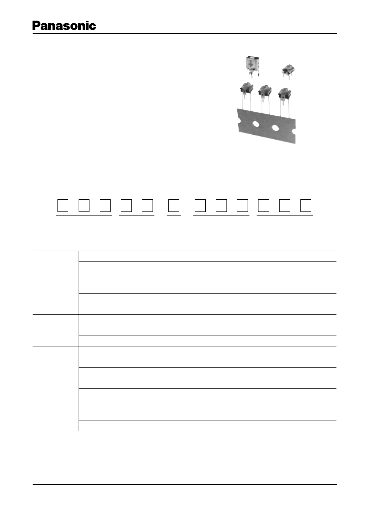
Side-adjust
●
No. 1
.............................................................................................................................................................
0.8±0.1
3-0.8±0.1
Knob color Orange yellow
Marking
6.4
#1 #3
#2
2.5 2.5
Carbon Composition Trimmer Po ten ti om e ters/EVND
1.2
φ3.2
1.7
0.75 0.75
1.85
4.65
0.4
4.5
3.8
8
Mounting
surface
0.6
2.5
φ2
Adjusting
direction
PWB mounting hole for reference
(Pitch tolerance: ±0.1)
View from mounting side
3-φ1.0
5.0
+
0.1
0
#1 #3
Circuit diagram
EVND2A
CW
#2
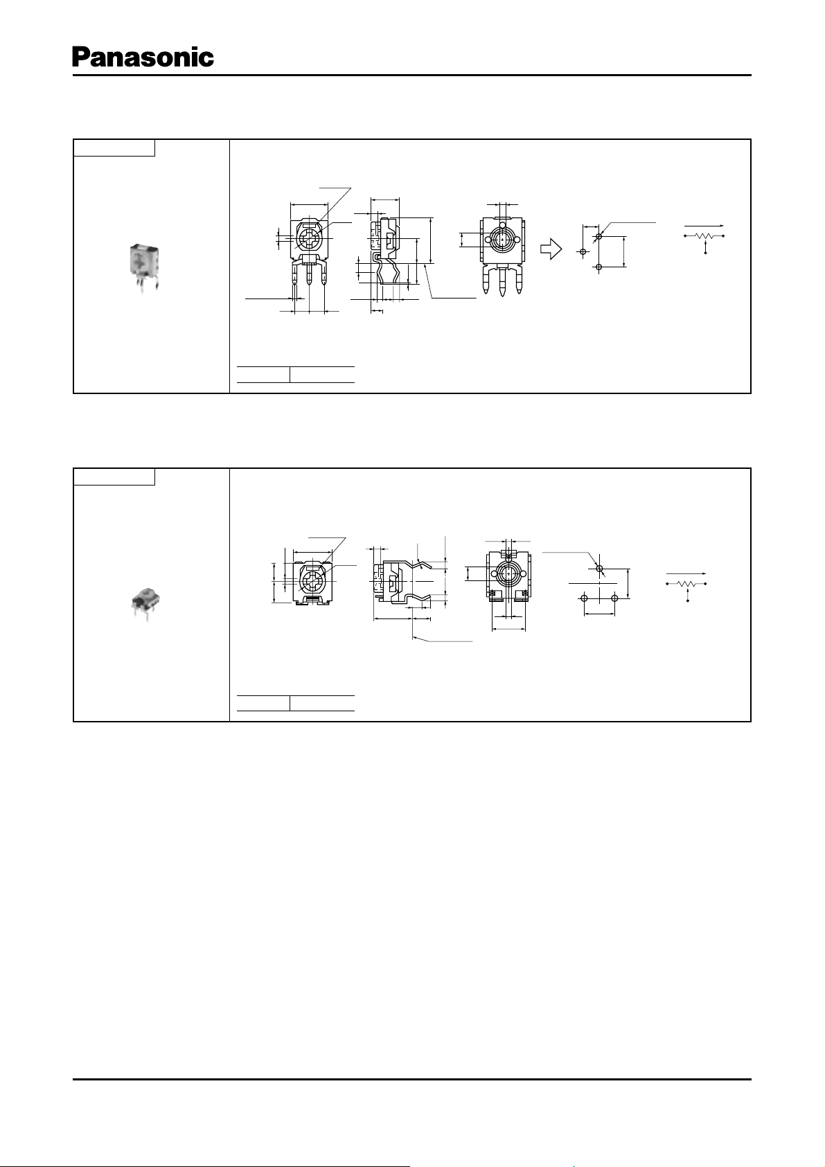
Top -adj u st
●
No. 2
...............................................................................................................................................................
Marking
6.4
#2
φ3.2
3.2
0.8±0.1
3.5
#1 #3
Knob color Orange yellow
1.2
6.35
0.3
1.7
3.5±0.5
0.75
0.75
Mounting
surface
φ2
3-0.8±0.1
0.6
5.0±0.2
+
0.1
3-φ1.0
0
#1 #3
5.0
5.0
PWB mounting hole for reference
(Pitch tolerance: ±0.1)
View from mounting side
Circuit diagram
CW
EVND8A
#2
Design and specifi cations are each subject to change without notice. Ask factory for the current technical specifi cations before purchase and/or use.
Should a safety concern arise regarding this product, please be sure to contact us immediately.
– EV23 –
Sep. 201000
Page 3

■ Radial Taping Prod ucts
Carbon Composition Trimmer Po ten ti om e ters/EVND
To p- adju s t
●
No. 3
To p- adju s t
●
No. 4
...............................................................................................................................................................
6.35
5.0
4.4 min.
12.7±1.0
1.3 max. 1.3 max.
+
0.8
3.85±0.70
0
A
φ4.0±0.3
6.35±1.30
P=12.7±0.3
A –
A
Adhesive tape shall
not be over from
base paper.
A
6.4
#2
φ3.2
3.2
0.8±0.1
3.5
#1 #3
3
0.8+0.1
Knob color Orange yellow
2–1.0±0.5
2-0.85
2-0.5
Resistance
1.6 max.
3.00±0.05
4
(0.25)
+
0.1
0
#1 #3
Circuit diagram
φ2
3 max.
5.00±0.05
6
CW
#2
1 max. 1 max.
Mounting
surface
0.3±0.1
0.6
3.0±0.3
+
0.1
φ1.3
(φ2.5)
2-φ1.0
PWB mounting
hole for reference
0.3±0.1
0
+
0.1
0
The pattern foil of PWB shall
not be in this dotted square
area.
1.2
(1.2)
(1.7)
0.25
21.0±0.5
...............................................................................................................................................................
6.4
Resistance
#2
3.23.5
0.8±0.1
φ3.2
#1 #3
Mounting surface
2-1.0±0.5
2-0.5
2-0.85
+
0.8±0.1
0.1
0
0.6
φ2
+
φ2–1.0
PWB mounting hole for reference
View from mounting side
Knob color Orange yellow
3.0±0.3
(φ2.5 )
0.1
0
4
(0.25)
5.00±0.05
CW
#1 #3
#2
Circuit diagram
Mounting
surface
+
0.1
φ1.3
0
3
1.6 max.
3.00±0.05
The pattern foil of PWB shall
not be in this dotted square
6
area.
1max. 1 max.
1.2
0.3
0.3±0.1
3.0
(0.25)
+
0.5
–
0.2
0.5
(1.7)
20.0±0.5
6.35±0.30
(11)
5.0±0.8
1.3 max.
12.7±1.0
3.85±0.70
6.35±1.3 0
A
P=12.7±0.3
EIAJ RC-1008 shall be applied
to items not specified here.
1.3 max.
Adhesive tape shall
not be over from
base paper.
Adhesive tape
A
φ4.0±0.3
EVNDJA
Section
2 max.
6.0±0.5
9.0±0.5
EVNDXA
A –
A
Section
2 max.
6.0±0.5
9.0±0.5
0.6±0.3
0.6±0.3
1.0
+
1.0
+
18.0
0.5
–
18.0
1.5 max.
0.5
–
1.5 max.
Side-adjust
●
............................................................................................................................................................
No. 5
6.8
3.4
3.4
CW
#1 #3
#2
Circuit diagram
φ1.3
φ2-1.0
5.00 ±0.05
2.50±0.05
1max.
(2.05)
1.7
φ3.2
(1.95)
0.3
+
0.1
0
0.9 2.50±0.35
+
0.1
0
1 max.
(1.95)
8
4.5
3
(0.5)
0.3
PWB mounting hole
for reference
View from mounting side
Knob color Orange yellow
Design and specifi cations are each subject to change without notice. Ask factory for the current technical specifi cations before purchase and/or use.
Should a safety concern arise regarding this product, please be sure to contact us immediately.
1.3 max. 1.3 max.
6.35±1.30
Resistance
20.0±0.5
3.85±0.70
0.8± 0.1
2.2
5.0 ±0.8
12.7±0.3
6.4
12.7±1.0
0.9
0.8±0.1
+
0.1
0.5
0
Adhesive tape
AA
φ40±0.3
– EV24 –
Mounting
surface
A – A
Section
Adhesive tape shall
not beoverfrom
base paper.
EVNDCA
0.6±0.3
1.5 max.
2 max.
6.0±0.5
9.0±0.5
1.0
0.5
–
+
18.0
Sep. 201000
 Loading...