

Page 1
Operating Instructions <Basics>
Installation Instructions provided
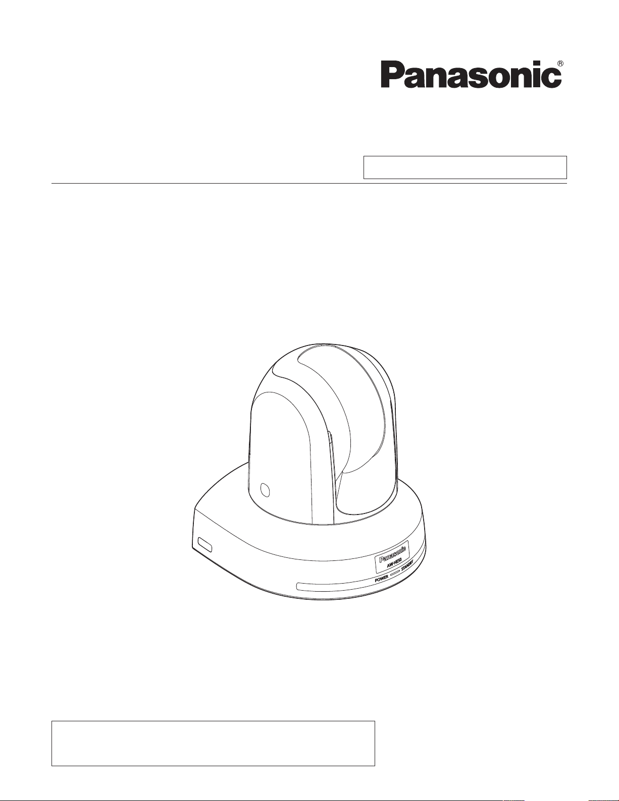
HD Integrated Camera
Model No. AW‑HE50HN
AW‑HE50SN
Before operating this product, please read the instructions carefully and save this manual for future use.
For instructions on how to operate this HD Integrated Camera and how
to establish its settings, refer to the “Operations and Settings” manual
(PDF file) which can be found on the CD-ROM supplied with the camera.
3TR006490BAA
Page 2
Safety precautions
CAUTION
RISK OF ELECTRIC SHOCK
DO NOT OPEN
CAUTION: TO REDUCE THE RISK OF ELECTRIC SHOCK,
REFER TO SERVICING TO QUALIFIED SERVICE PERSONNEL.
DO NOT REMOVE COVER (OR BACK).
NO USER SERVICEABLE PARTS INSIDE.
The lightning flash with arrowhead symbol,
within an equilateral triangle, is intended to
alert the user to the presence of uninsulated
“dangerous voltage” within the product’s
enclosure that may be of sufficient magnitude
to constitute a risk of electric shock to
persons.
The exclamation point within an equilateral
triangle is intended to alert the user to the
presence of important operating and
maintenance (service) instructions in the
literature accompanying the appliance.
WARNING:
THIS APPARATUS MUST BE EARTHED
To ensure safe operation, the three‑pin plug must
be inserted only into a standard three‑pin power
point which is effectively earthed through the normal
household wiring.
Extension cords used with the apparatus must
have three cores and be correctly wired to provide
connection to the earth. Wrongly wired extension
cords are a major cause of fatalities.
The fact that the apparatus operates satisfactorily
does not imply that the power point is earthed or that
the installation is completely safe. For your safety, if
you are in any doubt about the effective earthing of
the power point, please consult a qualified electrician.
For CANADA
This class A digital apparatus complies with
Canadian ICES-003.
Cet appareil numérique de la classe A est
conforme à la norme NMB-003 du Canada.
WARNING:
TO PREVENT INJURY, THIS APPARATUS
MUST BE SECURELY ATTACHED TO THE
FLOOR/WALL IN ACCORDANCE WITH THE
INSTALLATION INSTRUCTIONS.
CAUTION:
TO REDUCE THE RISK OF FIRE OR SHOCK
HAZARD AND ANNOYING INTERFERENCE, USE
THE RECOMMENDED ACCESSORIES ONLY.
FCC Note:
This equipment has been tested and found to comply
with the limits for a class A digital device, pursuant to
Part 15 of the FCC Rules. These limits are designed
to provide reasonable protection against harmful
interference when the equipment is operated in a
commercial environment. This equipment generates,
uses, and can radiate radio frequency energy, and if
not installed and used in accordance with the
instruction manual, may cause harmful interference
to radio communications. Operation of this equipment
in a residential area is likely to cause harmful
interference in which case the user will be required to
correct the interference at his own expense.
Warning:
To assure continued FCC emission limit compliance,
the user must use only shielded interface cables when
connecting to external units. Also, any unauthorized
changes or modifications to this equipment could void
the user’s authority to operate it.
CAUTION:
In order to maintain adequate ventilation, do not
install or place this unit in a bookcase, built-in
cabinet or any other confined space. To prevent
risk of electric shock or fire hazard due to
overheating, ensure that curtains and any other
materials do not obstruct the ventilation.
WARNING:
• TO REDUCE THE RISK OF FIRE OR ELECTRIC
SHOCK, DO NOT EXPOSE THIS APPARATUS TO
RAIN OR MOISTURE.
• THE APPARATUS SHALL NOT BE EXPOSED TO
DRIPP ING OR S PLASH ING AND TH AT N O
OBJECTS FILLE D WITH LIQUIDS , SUCH AS
VA SE S, S H A LL B E P L A C E D O N T H E
APPARATUS.
indicates safety information.
The socket outlet shall be installed near the
equipment and easily accessible or the mains plug or
an appliance coupler shall remain readily operable.
A warning that an apparatus with CLASS 1
construction shall be connected to a MAINS socket
outlet with a protective earthing connection.
2
Page 3
Safety precautions
IMPORTANT SAFETY INSTRUCTIONS
Read these operating instructions carefully before using the unit. Follow the safety instructions on the unit and the
applicable safety instructions listed below. Keep these operating instructions handy for future reference.
1) Read these instructions.
2) Keep these instructions.
3) Heed all warnings.
4) Follow all instructions.
5) Do not use this apparatus near water.
6) Clean only with dry cloth.
7) Do not block any ventilation openings. Install in
accordance with the manufacturer’s instructions.
8) Do not install near any heat sources such
as radiators, heat registers, stoves, or other
apparatus (including amplifiers) that produce heat.
9) Do not defeat the safety purpose of the polarized
or grounding‑type plug. A polarized plug has two
blades with one wider than the other. A grounding‑
type plug has two blades and a third grounding
prong. The wide blade or the third prong are
provided for your safety. If the provided plug does
not fit into your outlet, consult an electrician for
replacement of the obsolete outlet.
10) Protect the power cord form being walked on or
pinched particularly at plugs, convenience
receptacles, and the point where they exit from
the apparatus.
11) Only use attachments/accessories specified by
the manufacturer.
12) Use only with the cart, stand, tripod,
bracket, or table specified by the
manufacturer, or sold with the
apparatus. When a cart is used, use
caution when moving the
cart/apparatus combination to avoid
injury from tip‑over.
13) Unplug this apparatus during lightning storms or
when unused for long periods of time.
14) Refer all servicing to qualified service personnel.
Servicing is required when the apparatus has
been damaged in any way, such as power‑supply
cord or plug is damaged, liquid has been spilled or
objects have fallen into the apparatus, the
apparatus has been exposed to rain or moisture,
does not operate normally, or has been dropped.
indicates safety information.
3
Page 4

Contents
Safety precautions ........................................................... 2
Before use ......................................................................... 5
Overview ........................................................................ 5
Concerning the Operating Instructions .......................... 5
Required personal computer environment ..................... 6
Trademarks and registered trademarks ......................... 6
About copyright and licence ........................................... 6
Disclaimer of warranty .................................................... 7
Network security ............................................................ 7
Characteristics .................................................................. 8
Controller supported ........................................................ 9
Accessories ...................................................................... 9
Installation precautions ................................................. 10
Operating precautions ................................................... 12
Concerning the wireless remote control
(optional accessory) .................................................. 14
Parts and their functions ............................................... 15
Camera unit ................................................................. 15
Wireless remote control (optional accessory) .............. 17
Setting the remote control IDs ...................................... 19
How to install and connect the unit .............................. 20
When using the WV‑Q105 (optional accessory) .......... 24
Changing the direction of the nameplate ..................... 25
Removing the camera .................................................... 26
Stand-alone installation
(when the mount bracket is going to be used) ........ 27
Stand-alone installation
(when the mount bracket is not going to be used)
When installing the unit on a desktop .......................... 29
When mounting the unit on a tripod ............................. 29
Connections .................................................................... 30
Connections with an HD monitor ................................. 30
Connections with a controller
(AW‑RP655 or AW‑RP555) ................................. 31
System example 1 ........................................................ 32
System example 2 ........................................................ 33
Network settings ............................................................. 34
Installing the software .................................................. 34
Use the Easy IP Setup Software
to establish the unit’s settings ............................. 34
Troubleshooting .............................................................. 36
Appearance ..................................................................... 42
.... 29
Specifications ................................................................. 43
How the model’s Operating Instructions manuals are configured
The manual of this HD integrated camera (hereafter, “the unit”) is divided into two manuals: one is the <Basics>
(this manual), and the other is the <Operations and Settings> (CD‑ROM).
Before installing the unit, be sure to read the <Basics> to ensure that the unit is installed correctly.
This manual explains how to install the unit, and it details the network connection and setting procedures.
For details on how to operate the unit and select its settings, refer to the “Operating Instructions <Operations and
Settings>” (PDF file) on the CD‑ROM supplied with the unit.
To read PDF files, you will need Adobe
®
Reader® which is available from Adobe Systems.
4
Page 5

Before use
Overview
This unit is a compact full HD camera integrated with a
pan‑tilt head and featuring a newly developed 1/3‑inch full
HD MOS sensor and digital signal processor (DSP).
In addition to its optical 18 zoom lens, the unit comes
with a 10 digital zoom to achieve high‑quality shooting
that overflows with ambiance.
Two models are available: the HDMI model AW‑HE50H
which is ideal for distributing the signals of TV conference
and other video events, and the SDI output model
AW‑HE50S which is ideal for creating content.
Besides IP control, both models allow connection with
existing camera controllers by way of serial control.
Concerning the Operating
Instructions
For the purposes of this manual, the model number
AW‑HE50HN is referred to as the “AW‑HE50H”, the
AW‑HE50SN as the “AW‑HE50S” and model numbers
AW‑HE50HN and AW‑HE50SN will be referred to
together as the “AW‑HE50”.
Similarly, the model number AW‑RP655N is referred as
the “AW‑RP655”, the AW‑RP555N as the “AW‑RP555”
and the AW‑RP50N as the “AW‑RP50”.
5
Page 6
Before use
Required personal computer
environment
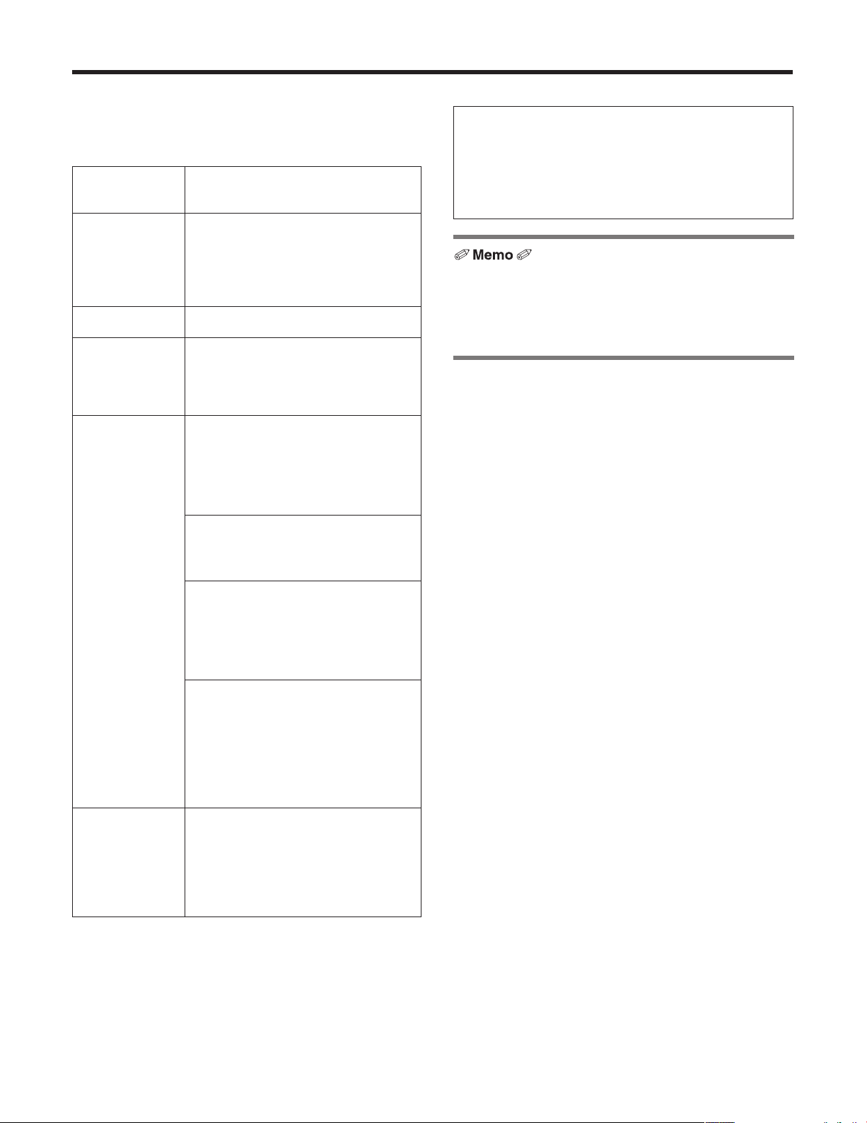
CPU Intel® CoreTM2 DUO 2.4 GHz or faster
recommended
Memory 512 MB or more
(When using Microsoft
Network function
Image display
function
1 GB or more, and when using
Microsoft
or 2 GB [64 bits] or more)
10Base‑T or 100Base‑TX port 1
Resolution: 1024 768 pixels or
Color generation: True Color 24 bits or
®
Windows® 7: 1 GB [32 bits]
®
Windows Vista®:
more
more
IMPORTANT
Failure to provide the required personal computer
environment may slow down the delineation of
the images on the screen, make it impossible for
the web browser to work and cause other kinds of
problems.
When using Microsoft® Windows Vista® or Microsoft®
Windows
Windows
for details on the personal computer environment that is
required and on the precautions and other items.
®
7, refer to the “Notes on Windows Vista®/
®
7” (page 84 in the <Operations and Settings>)
Supported
operating
system and
Web browser
Other CD‑ROM drive
Microsoft
64‑bit*
Microsoft® Windows® 7 Professional
32‑bit*
Windows® Internet Explorer® 8.0*
Microsoft® Windows Vista® Business
SP1 32‑bit
Windows
Microsoft
SP3*
Microsoft® Windows® XP Professional
Edition SP3*
Microsoft® Internet Explorer® 6.0 SP3
*1: This cannot be used in the
*2: This cannot be used with the 64‑bit
*3: The Microsoft
(for using the Operating Instructions and
various software)
Adobe
(for browsing the Operating Instructions
on the CD‑ROM)
®
Windows® 7 Professional
1
1
®
Internet Explorer® 7.0
®
Windows® XP Home Edition
3
3
®
Reader
®
Windows
version of Internet Explorer
Professional x64 Edition is not
supported.
2
XP compatibility mode.
®
8.0.
®
Windows® XP
®
Trademarks and registered
trademarks
Microsoft, Windows, Windows Vista, Windows 7 and
Internet Explorer are either registered trademarks or
trademarks of Microsoft Corporation in the United States
and other countries.
Intel and Intel Core are trademarks or registered
trademarks of Intel Corporation in the United States and
other countries.
Adobe and Reader are either registered trademarks or
trademarks of Adobe Systems Incorporated in the United
States and/or other countries.
Other names of companies and products contained
in these Operating Instructions may be trademarks or
registered trademarks of their respective owners.
About copyright and licence
Distributing, copying, disassembling, reverse compiling,
reverse engineering, and also exporting in violation of export
laws of the software provided with this unit are expressly
prohibited.
6
Page 7

Before use
Disclaimer of warranty
IN NO EVENT SHALL Panasonic System Networks Co., Ltd.
BE LIABLE TO ANY PARTY OR ANY PERSON, EXCEPT
FOR REPLACEMENT OR REASONABLE MAINTENANCE
OF THE PRODUCT, FOR THE CASES, INCLUDING BUT
NOT LIMITED TO BELOW:
1 ANY DAMAGE AND LOSS, INCLUDING WITHOUT
LIMITATION, DIRECT OR INDIRECT, SPECIAL,
CONSEQUENTIAL OR EXEMPLARY, ARISING OUT
OF OR RELATING TO THE PRODUCT;
2 PERSONAL INJURY OR ANY DAMAGE CAUSED BY
INAPPROPRIATE USE OR NEGLIGENT OPERATION
OF THE USER;
3 UNAUTHORIZED DISASSEMBLE, REPAIR OR
MODIFICATION OF THE PRODUCT BY THE USER;
4 INCONVENIENCE OR ANY LOSS ARISING WHEN
IMAGES ARE NOT DISPLAYED, DUE TO ANY
REASON OR CAUSE INCLUDING ANY FAILURE OR
PROBLEM OF THE PRODUCT;
5 ANY PROBLEM, CONSEQUENTIAL
INCONVENIENCE, OR LOSS OR DAMAGE,
ARISING OUT OF THE SYSTEM COMBINED BY
THE DEVICES OF THIRD PARTY;
6 LOSS OF REGISTERED DATA CAUSED BY ANY
FAILURE.
Network security
As you will use this unit connected to a network, your
attention is called to the following security risks.
1 Leakage or theft of information through this unit
2 Use of this unit for illegal operations by persons with
malicious intent
3 Interference with or stoppage of this unit by persons
with malicious intent
It is your responsibility to take precautions such as those
described below to protect yourself against the above
network security risks.
Use this unit in a network secured by a firewall, etc.
If this unit is connected to a network that includes PCs,
make sure that the system is not infected by computer
viruses or other malicious entities (using a regularly
updated antivirus program, anti‑spyware program, etc.).
Protect your network against unauthorized access by
restricting users to those who log in with an authorized
user name and password.
Apply measures such as user authentication to protect
your network against leakage or theft of information,
including authentication information (user names and
passwords), FTP server information and DDNS server
information.
Do not install the camera in locations where the camera
or the cables can be destroyed or damaged by persons
with malicious intent.
7
Page 8

Characteristics
Multiple number of formats supported
Switching between the 1080/59.94i, 720/59.94p and
480/59.94i formats can be accomplished using a menu.
By using VIDEO OUT signals, HD format signals and SD
format signals can be output at the same time.
With the SD format, either Squeeze (16:9), LetterBox
(16:9) or SideCut (4:3) can be selected.
1/3-inch MOS sensor and high-performance 18 zoom
lens featured
A newly developed 1/3‑inch full HD MOS sensor and
DSP (digital signal processor) are incorporated.
High‑quality pictures are obtained by video processing in
many different kinds of ways.
In addition to its optical 18 zoom lens, the unit comes
with a 10 digital zoom to achieve high‑quality images
that overflow with ambiance.
A dynamic range stretch (DRS) function that
compensates for overexposure and loss of dark detail
and a new hybrid digital noise reduction (Hybrid DNR)
function for minimizing image lag even in dark locations
and shooting scenes clearly are incorporated to
reproduce clean and clear images in a wide range of
applications.
Easy operation of unit enabled by its integration with a
high-performance pan-tilt head unit
Operations at the high speed of 90°/s
Wide rotational angles with a panning range of ±175° and
a tilting range from –30° to +90°
Quiet operation with noise levels of NC35 (normal speed)
and NC40 (when preset)
Storage of up to 100 positions in the preset memory
(The number of preset memory settings differs depending
on the controller that is used with the unit.)
High degree of compatibility with Panasonic’s currently
available controllers, enabling a flexible system to be
put together
A maximum of five units can be operated by serial control
from one of Panasonic’s currently available controllers
(AW‑RP655, AW‑RP555 and AW‑RP50).
(It may be necessary to upgrade the version of the
controller in order to support the unit. The maximum
distances between the units and controller is 1000 meters
(3280 ft.). Use of an external device or some other means
must be provided separately in order to extend the video
signal connections.)
The unit can also be used together with the cameras
and pan‑tilt head unit systems currently available from
Panasonic System Networks Co., Ltd. so that an existing
system can be used to advantage to put together a
system that is even more flexible.
Integrated pan-tilt head unit, camera and lens to
facilitate installation
By designing the camera, lens and pan‑tilt head as a
single integrated unit, the time taken for the installation
work has been drastically reduced.
Use of easy-to-operate wireless remote control (optional
accessory) is possible
A wireless remote control capable of operating up to four
units can be used.
It can easily be used to set the various functions or switch
between them while viewing the menu screens.
Flexible camera layout enabled by simple connection
and installation
This unit features excellent connectivity and installability
thanks to the IP control; a lightweight main unit, and the
turn‑lock mechanism, which enables the user to install it
on his or her own (only when used indoors).
Energy-savings achieved by the compact main unit
design
By slimming down the unit’s weight and dimensions,
a low power consumption is yielded, and even the
connection of a multiple number of units poses no
concerns.
Easy connections and settings courtesy of IP control
Up to a hundred units can be operated by IP connection
from a Panasonic controller (AW‑RP50).
(The maximum length of the LAN cables is 100 meters
[328 ft.].)
By automatically recognizing the IP addresses and
changing their allocation, the previous restrictions on
the connections between the cameras and controllers
using serial interfaces and the time and trouble taken
to establish the various settings can be significantly
reduced, and by configuring a network, flexible camera
control can be implemented anywhere with any of the
cameras.
8
Page 9

Controller supported
AW-RP655
AW-RP555
AW-RP50
It may be necessary to upgrade the version of the
controller in order to support the unit.
Consult with your dealer.
Notes
When connecting the AW-RP655
The camera menus that are operated using the
LCD panel on the AW‑RP655 cannot be used.
Use the camera menus displayed on the monitor
which has been connected to the unit.
When connecting the AW-RP555
The AW‑RP555 periodically transmits the
POWER‑ON command to the pan‑tilt head.
This means when the unit has been selected from
the AW‑RP555, its power will be turned on again
after several seconds even if the unit has been
set to the standby mode by the web browser,
IP‑connected controller or wireless remote control
(optional accessory).
Accessories
Check that the following accessories are present and accounted for.
Operating Instructions <Basics> (this manual) ................... 1
Op erating Instructions <Operations and Settings>
(CD‑ROM) ...................................................................... 1
Mo unt bracket for installation surface
(Hanging / Desktop) ....................................................... 1
Bracket mounting screws (bind‑head)
Main unit mounting screw
M3 6 mm ....................................................................... 1
(with flat washer, spring washer)
M4 10 mm .......... 4
Drop‑prevention wire (already attached to the main unit) ... 1
Power cable (2 m [6.6 ft.]) ................................................... 1
Cable cover ......................................................................... 1
AC adapter ......................................................................... 1
9
Page 10
Installation precautions
In addition to heeding the points presented in the “Safety precautions”, observe the following precautions
as well.
Ensure that the installation work complies with the
technical standards governing electrical equipment.
This unit is for indoor use only.
It cannot be used outdoors.
Avoid installation in a location where the unit will be exposed
to direct sunlight for extended periods or near a cooling or
heating appliance.
Otherwise, deformation, discoloration, malfunctioning and/or
problems in operation may result. Operate the unit where it
will not be splashed or sprayed by water.
Use the unit with an installation where the unit is
suspended from an overhead surface or with a
stand-alone installation.
Do not use the unit on its side or tilted at an angle.
Notes
Be absolutely sure to use the four bracket mounting
screws (M4) for mounting the mount bracket.
These are supplied with the unit. Do not use wood
screws, nails, etc.
In the case of a concrete ceiling, secure the unit using
anchor bolts (for M4) or AY plug bolts (for M4).
Recommended clamping torque
M4: 1.47 N · m (15 kgf · cm)
The withdrawal strength of the mounting location for
each screw must be at least 196 N (20 kgf).
When mounting the unit on a ceiling made of
plasterboard, for instance, if it is not strong enough
to support its weight, either reinforce the ceiling
adequately or use the WV‑Q105 direct ceiling mount
bracket, which is sold separately.
When using a mount bracket which is sold separately,
read the handling instructions.
Do not hold the camera head while undertaking the
installation work. Doing so may cause malfunctioning.
Concerning the installation location
Install the unit in a stable location which will not be
susceptible to shaking. If the unit is installed in a location
which is susceptible to shaking, this will cause the unit’s
images to shake in turn.
Install the unit after conferring in detail with your dealer.
Install the unit on a ceiling that is strong enough (such as a
concrete ceiling).
If the unit is to be installed on a ceiling which is not strong
enough, reinforce the ceiling sufficiently first.
Do not install or use the unit in the following kinds of
locations.
On walls (where the unit would be installed sideways)
In locations (including places such as under the eaves of
a building) where the unit would be directly exposed to
rain or water
In locations such as kitchens where there are high
concentrations of steam and grease
In outdoor locations or hot places where the temperature
will exceed 40 °C (104 °F)
In cold locations where the temperature will drop below
0 °C (32 °F)
In locations where the humidity will exceed 85 %
In locations where chemicals are used such as near
swimming pools
At sea, in coastal areas or in locations where corrosive
gases are emitted
In locations where radiation, X‑rays, or strong radio
waves or magnetic fields are generated
In locations where the unit would be subject to a great
deal of vibration such as on board a vehicle or ship (this
unit is not designed to be used in vehicles)
In locations where the temperature is subject to sudden
changes such as near the air outlet of an air conditioner
or near a door which allows the outside air to come in
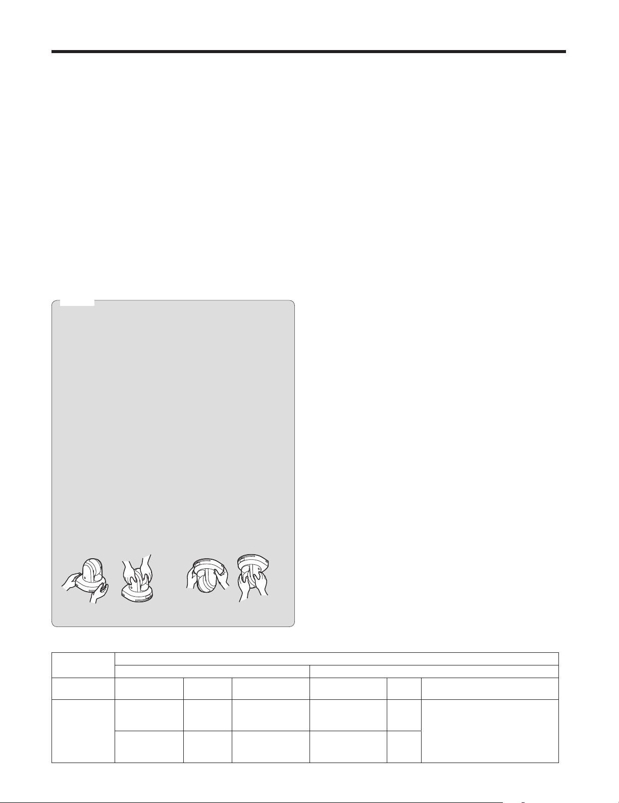
OK NGOK NG
Desktop installation Hanging installation
AW-HE50
main unit
Mass Model No. Mass Mounting
Approx.
1.4 kg
[3.09 lbs.]
(Including
mount bracket)
Direct mount
accessory)
WV‑Q105
accessory)
Applicable mount bracket Mounting onto the ceiling
(supplied
(optional
Approx.
0.23 kg
[0.51 lbs.]
Approx.
0.15 kg
[0.33 lbs.]
Hanging/Desktop
What to avoid to ensure that the unit will perform stably
over a prolonged period
Using the unit for a prolonged period in a location with
high temperature and humidity levels will cause its parts
to deteriorate and shorten its service life.
Ensure that a cooling unit or heating unit will not blow any
air directly toward the installation location.
Mounting conditions
Recommended
screws
M4 screws
(supplied
accessory)
For ceiling M4 screws 4
No. of
screws
10
Minimum withdrawal strength
4
Ensure that the mounting strength
can support a weight that is at
least five times the total mass
of the equipment, including the
camera’s main unit.
(per screw)
196 N (20 kgf)
Page 11

Installation precautions
Be absolutely sure to use the bracket and screws
supplied when installing the unit.
Do not mount the unit by employing any methods other
than those specified.
Do not remodel the mounting bracket or mounting screws
provided with the unit.
Tightening up the mounting screws
Tighten up the screws and bolts securely to the degree
that is appropriate for each of the materials used in the
mounting location and structures.
After tightening up the screws and bolts, check that
there is no unsteadiness and that the parts have been
tightened securely.
Use the specified tools and tighten the screws firmly.
When the unit is no longer going to be used, do not
leave it lying around, but be absolutely sure to dispose
of it properly.
For details on how to remove the unit, refer to “Removing
the camera” (page 26).
When installing, transferring or disposing of the unit, be
absolutely sure to hold it by its pedestal area.
Problems may result if the camera head is held or rotated.
Do not attach a filter, hood, extender or other parts to
the unit.
Use the dedicated AC adapter and power cable provided
with the unit.
Connect the AC adapter and power cable to the power inlet
securely.
Installing the AC adapter
Do not place the adapter directly onto a ceiling panel or
other such surface.
Extreme danger is posed when water has collected on
the surface as a result of leaking rain, for instance.
Secure the adapter firmly to the bottom or other surface
of a reinforcing member made of channel steel where
dust and other foreign matter will not accumulate.
(Refer to page 24.)
Secure the adapter firmly so that there will be no chance
that it will fall off or fall down.
Secure it using a strength which can withstand the mass
(approx. 320 g [0.71 lbs.]) of the AC adapter.
Install the accessory AC adapter near the main power
outlet, and position it in such a way that its power plug
can be plugged into and unplugged from the outlet easily.
When connecting the AC adapter to a power outlet on the
ceiling or on any other surface where dust may collect, wipe
off the dust on the power plug at periodic intervals as an
anti‑tracking measure.
Connecting the power cable
Be absolutely sure to connect the power cable of the
AC adapter through a circuit breaker using one of the
following methods.
(1) Connect the power cable through a power control unit.
(2) Connect the power cable to a circuit breaker in a
power distribution panel with a contact distance of
3.0 mm or more.
Use a circuit breaker which is capable of shutting
off all the poles of the main power supply with the
exception of the protective ground conductor.
(3) Install the AC adapter near the power outlet, and
connect it through the power plug.
Grounding
Before using the unit, check that the grounding wire has
been fastened securely.
Check the grounding resistance (less than 100 ) of the
grounding terminal.
When the power plug is to be converted into a 2‑pin plug
for use, first consult with your dealer. Then use a plug
adapter which is equipped with a grounding terminal, and be
absolutely sure to connect this terminal to ground.
In a case like this, be absolutely sure to make the
connection to ground before proceeding to connect the
power plug to the main power source.
Similarly, before the ground connection is
to be disconnected, be absolutely sure to
disconnect the power plug from the main
power source first.
If there is a possibility of noise interference
Either wire the cables so that the power cable (ceiling light
cord) of AC 100 V or more, and the signal cable are placed
at least 1 meter (3.3 ft.) apart. Alternatively run each cable
through its own metal conduit. (The metal conduits must be
grounded.)
Radio signal interference
If the unit is positioned near a TV or radio transmitting
antenna or a strong electrical field or magnetic field (such as
that generated by a motor, transformer or power lines), its
images may be distorted and/or the images may be affected
by noise.
When connecting the cables, ensure that the connector
areas will not be subject to any load.
Doing so may cause malfunctioning.
Allowing the generated heat to escape
This unit allows the heat generated inside to escape from its
surfaces.
Do not install the unit in a location where it will be
surrounded by walls or other surfaces and where heat will
be trapped.
Power switch
This unit does not have a power switch. The power turns
on when its power plug is connected to a power outlet.
When the power is turned on, the pan, tilt, zoom and
focusing operations are performed. Before proceeding with
maintenance, be absolutely sure to disconnect the power
plug from the power outlet.
IMPORTANT
The product name and its electrical ratings are
marked on its bottom panel.
11
Page 12

Operating precautions
Shoot under the proper lighting conditions.
To produce pictures with eye‑pleasing colors, shoot under
the proper lighting conditions.
The pictures may not appear with their proper colors when
shooting under fluorescent lights.
Select the proper lighting as required.
To ensure a stable performance in the long term
Using the unit for prolonged periods in locations where the
temperature and humidity levels are high will cause its parts
to deteriorate, resulting in a reduction of its service life.
(Recommended temperature: Max. 35 °C [95 °F])
Ensure that a cooling unit or heating unit will not blow any
air directly toward the installation location.
Image persistence on the MOS sensor color filters
If parts of the MOS sensor are exposed continuously to
spotlights or other bright lights, the color filters inside the
MOS sensor will deteriorate, and the parts concerned may
become discolored. The discoloration may be noticeable
when the direction of fixed monitoring is changed.
Do not point the camera at strong
lights.
When parts of the MOS sensor are
exposed to spotlights or other strong
lights, blooming (a phenomenon where
the edges of strong lights become
blurred) may occur.
Blooming
Concerning the color reproduction of MOS sensors
Depending on the color tones of the subjects, the color
reproduction may deteriorate: This is normal and not
indicative of any trouble.
What happens with high-brightness subjects
Flare may occur if an extremely bright light source is pointed
at the lens. In a case like this, change the angle or take
some other remedial action.
When using the automatic functions
If “FullAuto” has been selected as the setting for Scene
on the camera menu, for example, all the auto settings
will be turned on, and manual operations will no longer be
possible for some of the items.
When using the ATW (auto tracking white adjustment)
function under fluorescent lights, the white balance may
vary.
In some situations, it may be hard to focus at the auto
setting. In cases like this, select the manual setting, and
focus manually.
The appropriate brightness may not be obtained when
shooting bright objects using the auto settings for the
gain and iris. In cases like this, set the shutter speed to
manual, and adjust.
Bright subject
Zooming and focusing
When the focus is set manually, out‑of‑focusing may occur
during zooming.
After zooming, if necessary, either adjust the focus or set the
focus to auto.
When using the focus at the manual setting, proceed with
zooming after setting the focus position at the Tele end
where the focusing accuracy is higher.
(However, if the distance from the unit to the subject is less
than 1.5 meters [4.92 ft.], the subject may shift out of focus
at the Wide end.)
If zooming is performed to the Tele end after having adjusted
the focus at the Wide end, out‑of‑focusing may occur.
Concerning the zoom position when the power is turned
on
When the unit’s power is turned on, the zoom, focus and iris
return to the positions they occupied immediately before the
power was turned off. (This happens for the focus and iris
when they were set manually.)
However, this position may not be restored if, for instance,
the power cable was disconnected during operation.
The unit comes with the safe mode.
The safe mode is function designed to protect the unit from
damage.
For further details, refer to “Safe mode” (page 83 in the
<Operations and Settings>).
Operating temperature range
Avoid using the unit in cold locations where the temperature
drops below 0 °C (32 °F) or hot locations where the
temperature rises above +40 °C (104 °F) since these
temperatures downgrade the picture quality and adversely
affect the internal parts.
Concerning the VIDEO OUT signal
The VIDEO OUT signal of the MULTI‑I/F connector is
provided in case the images are to be monitored.
Color bars
Color bars are used to adjust the color phase, and the
widths and positions of these bars may differ from other
models.
The setting for the Down CONV. Mode item when color
bars are displayed is fixed at “Squeeze”.
If “SideCut” or “LetterBox” has been selected, the HDMI
output will not appear for a few seconds when the color
bar display is set to ON or OFF.
12
Page 13

Operating precautions
Turn off the power before connecting or disconnecting
the cables.
Always be sure to turn off the power before connecting or
disconnecting the cables.
Handle the unit carefully.
Do not drop the unit or subject it to strong impact or
vibration. Doing so may cause the unit to malfunction.
When the unit is not in use
Turn off the unit’s power when it is not in use.
When the unit is no longer going to be used, do not leave it
lying around, but be absolutely sure to dispose of it properly.
Do not touch the optical system parts.
The optical system parts are the very heart of the camera.
Under no circumstances must they be touched.
In the unlikely event that they have become dusty, remove
the dust by using a camera blower or by wiping them gently
with a lens cleaning paper.
Personal computer used
If the same image is displayed for a prolonged period on a
PC monitor, the monitor may be damaged. Use of a screen
saver is recommended.
Maintenance
Turn off the unit’s power before proceeding with
maintenance.
Otherwise, you may injure yourself.
Wipe the surfaces using a soft dry cloth. Avoid all contact
with benzene, paint thinners and other volatile substances,
and avoid using these substances. Otherwise, the casing
may become discolored.
Do not turn the camera head by hand.
Turning the camera head by hand may cause the unit to
malfunction.
Use the unit in an environment with minimal moisture
and dust.
Avoid using the unit in an environment with high
concentration of moisture or dust since these conditions will
damage the internal parts.
Disposal of the unit
When the unit has reached the end of its service life and is
to be disposed of, ask a qualified contractor to dispose of
the unit properly in order to protect the environment.
Do not allow foreign matter to make contact with the
rotating parts.
Otherwise, trouble may be caused.
Self-diagnosis function
When an abnormal operation caused by the effects of
extraneous noise or other factors continues for more
than 30 seconds during use, the unit’s reset operation
will automatically be triggered, after which the unit will
restart. After it has started up again, the same initialization
operation as when the power is turned on will be performed.
If abnormal operations occur frequently, it may be because
high levels of extraneous noise are being generated in the
environment where the camera has been installed.
These events will cause problems in the camera so consult
with your dealer as soon as possible.
Keep the unit away from water.
Avoid all direct contact with water. Otherwise, problems may
occur.
13
Page 14

Concerning the wireless remote control (optional accessory)
This unit can be operated by remote control using a
wireless remote control (model number: AW-RM50G)
purchased separately.
Check out the following points before using the wireless
remote control.
Consult your dealer concerning the purchase of a
wireless remote control.
Operate the wireless remote control from positions
less than 10 meters (32.8 ft.) away from the unit.
The wireless remote control may not work when it is
pointed from certain angles at the unit.
From a place where the wireless remote control signal
light‑sensing area (hereafter, “light‑sensing area”) can
be seen, point the signal transmission window of the
wireless remote control at the light‑sensing area, and
operate the buttons.
It may prove to be more difficult to operate the unit when
the remote control is operated from behind the unit.
If the unit is installed near fluorescent lights, plasma
monitors or other such products or if the unit is
exposed to sunlight, the effects of the light may make
it impossible for the unit to be operated using the
wireless remote control.
Be sure to follow the steps below for installation and use.
• Take steps to ensure that the light‑sensing area will not
be exposed to the light from fluorescent lights, plasma
monitors or other such products or from the sun.
• Install the unit away from fluorescent lights, plasma
monitors and other such products.
For about 10 minutes even after the batteries have
been removed from the wireless remote control,
the selection of the operation to be performed (the
[CAM1], [CAM2], [CAM3] or [CAM4] button which
was pressed last) will remain stored in the memory.
When a longer period of time elapses, however, the
selection is reset to the status established when the
[CAM1] button was pressed.
14
Page 15
Parts and their functions
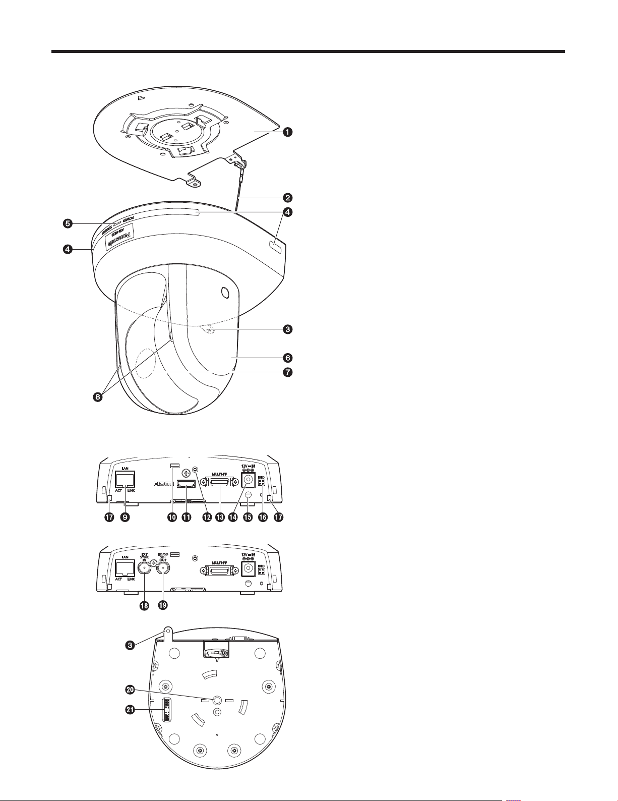
Camera unit
1 Mount bracket for installation surface
(supplied accessory)
Mount this bracket onto the installation surface, and then
attach the camera main unit to the bracket.
2 Drop-prevention wire
Pull out the wire from the bottom panel of the camera
main unit, and attach it to the hook of the mount bracket.
3 Hole for securing the camera pedestal
This hole is provided in the bottom panel of the camera
pedestal.
4 Wireless remote control signal light-sensing
area
Light sensors are located in four places; at the front of the
camera pedestal and on either side.
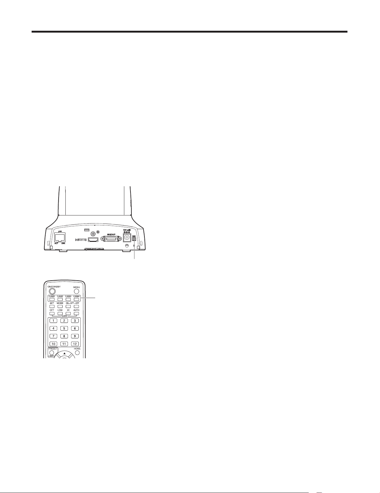
<Rear panel (AW-HE50H)>
<Rear panel (AW-HE50S)>
<Bottom panel>
5 Status display lamp
This lights in the following way depending on the status of
the unit.
Orange: When the standby status is established
Green: When the power is on
Red: When trouble has occurred in the unit
Green and blinks twice:
When a signal matched by the remote control
ID has been received from the wireless
remote control (optional accessory) while the
power is on
Orange and blinks twice:
When a signal which is not matched by the
remote control ID has been received from the
wireless remote control (optional accessory)
while the power is on
6 Camera head
This rotates in the horizontal direction.
7 Lens unit
This rotates in the up and down direction.
8 Tally lamp
This comes on or goes off in response to the control from
the controller but only when “On” has been selected as
the tally lamp use setting.
15
Page 16
Parts and their functions
9 LAN connector for IP control [LAN ACT/LINK]
This LAN connector (RJ45) is connected when exercising
IP control over the unit from an external device.
Use a cable with the following specifications for the
connection to the LAN connector:
When connecting through a hub:
LAN cable* (category 5 or above, straight cable),
max. 100 meters [328 feet]
When a hub is not used:
LAN cable* (category 5 or above, crossover cable),
max. 100 meters [328 feet]
*: Use of an STP (shielded twisted pair) cable is
recommended.
Anti-theft wire mounting hole
Use this hole to attach the wire bracket.
HDMI connector [HDMI] (AW-HE50H only)
This is the HDMI video output connector.
Hole used to secure cable cover
Use the screw provided to secure the cable cover.
MULTI-I/F connector [MULTI-I/F]
This is the camera’s HD/SD component video signal,
composite video signal and camera’s control signal
connector.
Use the multi‑interface cable purchased separately or a
cable with the DX40M‑20P (made by Hirose) connector
specifications as the connecting cable.
1A10A
1B10B
The above figure
shows the pin
layout of the
connector on the
camera as seen
from the outside.
Pin
Signal name
No.
1A Y OUT 6A RX+_IN
1B Y GND 6B RX–_IN
2A Pb OUT 7A TX+_IN
2B Pb GND 7B TX–_IN
3A Pr OUT 8A GND
3B Pr GND 8B GND
4A VIDEO OUT 9A RX+_OUT
4B VIDEO GND 9B RX–_OUT
5A TALLY 10A TX+_OUT
5B T GND 10B TX–_OUT
Pin
No.
Signal name
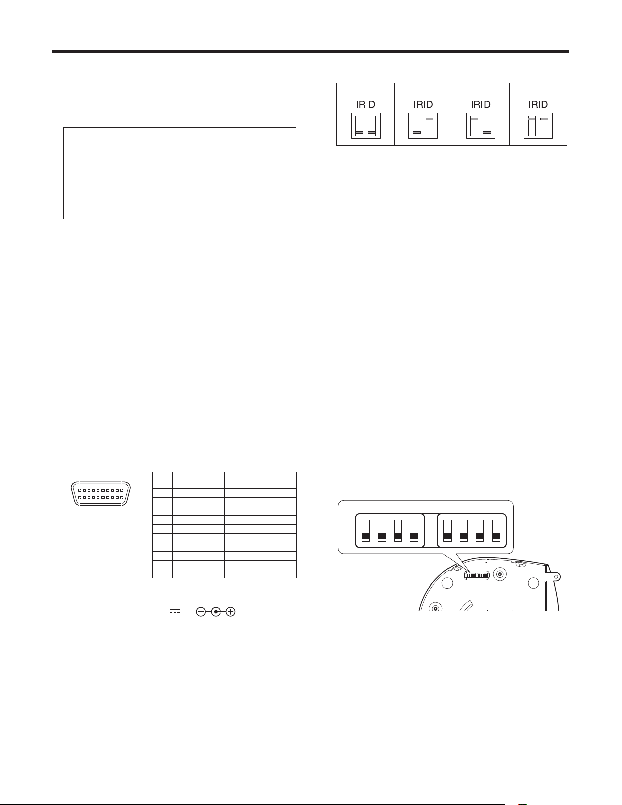
IR ID switches [IRID]
[CAM1] [CAM2] [CAM3] [CAM4]
These are used to select the ID of the wireless remote
control (optional accessory).
The IR ID switch settings “CAM1” to “CAM4” correspond
to the [CAM1] to [CAM4] buttons on the wireless remote
control.
Square holes (2) for cable cover tabs
The tabs on the two sides of the cable cover are fitted
into these holes.
SYNC IN connector [EXT SYNC IN]
(AW-HE50S only)
This is the external sync signal input connector.
This unit supports the BBS (Black Burst Sync) signal as
the external sync signal.
SDI OUT connector [HD/SD SDI OUT]
(AW-HE50S only)
This is the SDI video signal output connector.
Threaded hole (thread: 1/4-20UNC) for mounting
the camera
Use this hole when mounting the camera on a tripod, etc.
Service switches
SW1
SW2 SW3 SW4 SW5 SW6 SW7 SW8
ON
OFF
DC IN connector [12V IN ]
Connect the AC adapter supplied with the unit to this
connector to supply the DC 12 V voltage to the unit.
Cable clamp
This is used to hold the cable connection to the DC IN
connector and prevent it from becoming disconnected.
The camera is used with all the switches at the OFF
setting.
16
Page 17
Parts and their functions
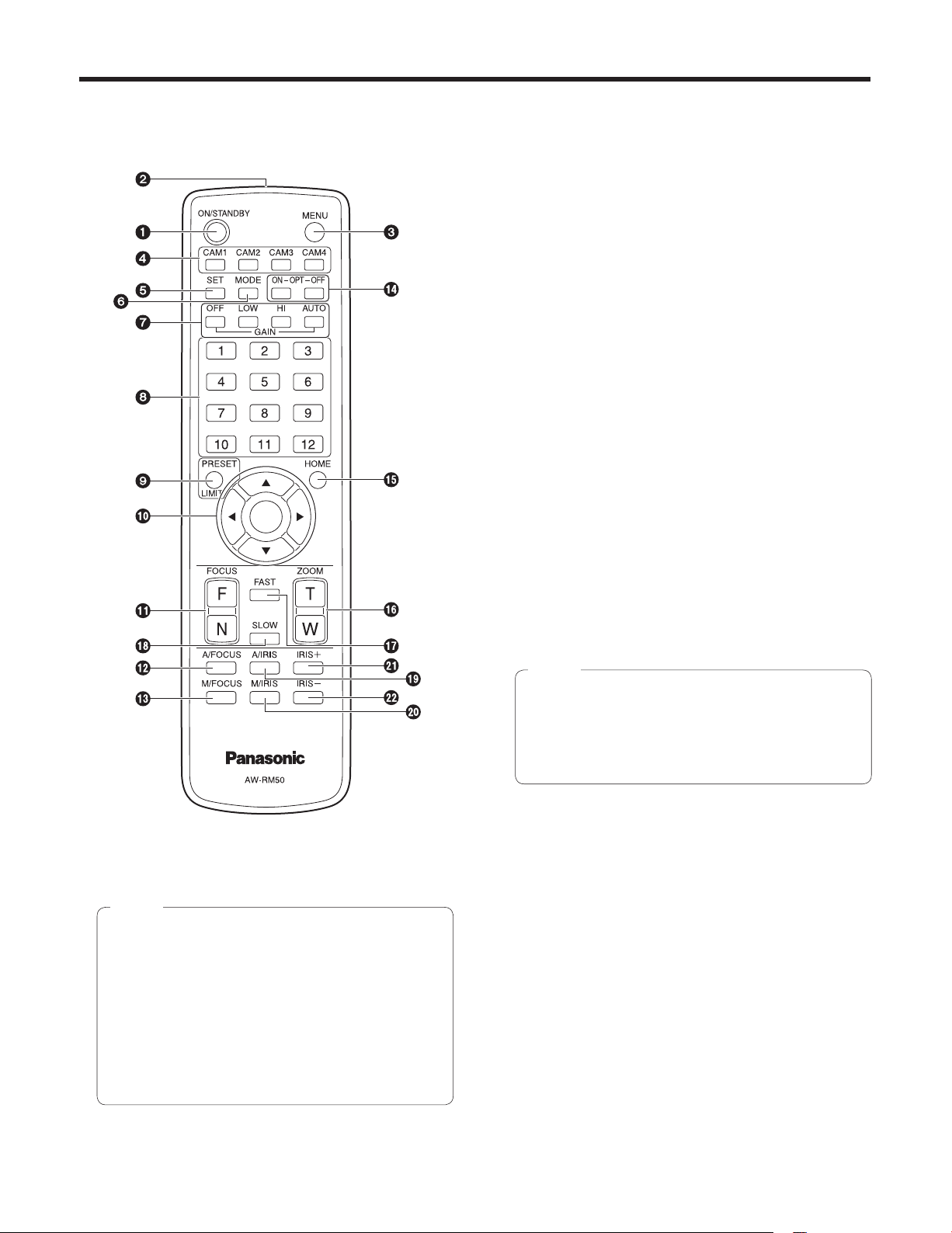
Wireless remote control
(optional accessory)
3 MENU button
Each time this is pressed for 2 seconds, operation
switches between displaying the unit’s menu and exiting
the menu.
When it is pressed quickly (for less than 2 seconds) while
a menu is displayed, the setting change is canceled.
Furthermore, the pan and tilt movement range limits
(limiters) are set and released by operating the MENU
button, PRESET/LIMIT button and the pan‑tilt buttons
([], [], [] and []).
For details, refer to “Setting/releasing the limiters”
(pages 81 to 82 in the <Operations and Settings>).
4 CAM1 to CAM4 buttons
These are used to select the units that are to be
operated.
Once a button has been selected, the unit corresponding
to the selected button can be operated.
5 SET button
If this button is pressed when one of the “Manual1 to 3”
settings has been selected for “Scene” on the camera
menu and the AWB A memory or AWB B memory has
been selected by the white balance adjustment, the white
balance is automatically adjusted and registered in the
selected memory.
1 ON/STANDBY button
Each time this is pressed for 2 seconds, operation
switches between turning on the unit’s power and
establishing the standby status.
Notes
When operation is transferred to the standby mode:
The current pan‑tilt position is stored in the memory
(as a POWER ON preset), and the panning/tilting
moves so that the camera points in the backward‑
facing direction.
When operation is transferred to the POWER ON
mode: Panning/tilting moves to the position which
was stored in the memory (as a POWER ON
preset) when operation was transferred to the
standby mode.
6 MODE button
This is used to select the video signals which are output
from the unit.
Each time it is pressed, the signals are switched between
the color bar signals and camera video signals.
Note
The setting for the Down CONV. Mode item when
color bars are displayed is fixed at “Squeeze”.
If “SideCut” or “LetterBox” has been selected, the
HDMI output will not appear for a few seconds
when the color bar display is set to ON or OFF.
7 GAIN buttons [OFF] [LOW] [HI] [AUTO]
These are used to set the gain.
The gain increase can be set in three steps using the
[OFF], [LOW] and [HI] buttons.
[LOW] is set to 9 dB, and [HI] is set to 18 dB.
When the [AUTO] button is pressed, the AGC function
is activated, and the gain is adjusted automatically
depending on the light quantity.
The maximum gain of the AGC function can be set using
the menu.
8 Preset memory call buttons [1] to [12]
These are used to call the information on the unit’s
directions and other settings, which have been registered
in the unit’s preset memories No.1 to No.12, and
reproduce those settings.
Settings in preset memories No.13 and above cannot be
called from the wireless remote control.
2 Signal transmission window
17
Page 18

Parts and their functions
9 PRESET/LIMIT button
This is used to register the settings in the preset
memories or set or release the limiters.
When a preset memory call button is pressed while the
PRESET/LIMIT button is held down, the information on
the unit’s current direction and other settings is registered
in the call button.
Preset memory call buttons [1] to [12] correspond to the
unit’s No.1 to No.12 preset memories.
Furthermore, the pan and tilt movement range limits
(limiters) are set and released by operating the PRESET/
LIMIT button, MENU button and the pan/tilt buttons ([],
[], [] and []).
For details, refer to “Setting/releasing the limiters”
(pages 81 to 82 in the <Operations and Settings>).
Pan-tilt buttons and menu operation buttons
[] [] [] [] []
(1) These are used to change the unit’s direction.
The unit is tilted in the up/down direction using the
[] and [] buttons and panned in the left/right
direction using the [] and [] buttons.
The [] button does not work during tilting and
panning.
When the [] or [] and [] or [] buttons are
pressed at the same time, the unit moves diagonally.
(2) The buttons are used for menu operations when the
unit displays the menus.
Use the [], [], [] and [] buttons to select the
menu items.
When a selected item has a sub‑menu, the sub‑menu
will be displayed by pressing the [] button.
When the cursor is aligned with a particular item and
the [] button is pressed on the setting menu at the
bottom hierarchical level, the setting of the selected
item blinks.
When the [] button is pressed after the setting
has been changed using the [], [], [] and []
buttons, the setting stops blinking, and the new
setting is entered.
With a regular menu, the new setting is reflected
immediately after it has been changed if the change
was made from the setting in the blinking status, but
there are some menus (Scene, Format and Initialize)
where it is reflected only after the [] button has
been pressed, the blinking has stopped and the new
setting has been entered.
If the MENU button is pressed quickly (for less than
2 seconds) while the setting is in the blinking status,
the change will be canceled, and the setting selected
prior to the change will be restored.
FOCUS buttons [F] [N]
These are used to adjust the lens focus manually when
the manual setting is established for the lens focus.
The focus is adjusted in the far using the [F] button and in
the near using the [N] button.
A/FOCUS button
This is used when automatically adjusting the lens focus.
M/FOCUS button
This is used when manually adjusting the lens focus.
The FOCUS buttons ([F] and [N]) are used when
performing the actual adjustment.
OPT buttons [ON] [OFF]
These are used for future expansion of the functions.
They are not used at the present time.
HOME button
When this is pressed for 2 seconds, the unit’s direction
(panning or tilting) returns to the reference position.
ZOOM buttons [T] [W]
These are used to adjust the lens zoom.
The zoom is adjusted in the wide‑angle using the [W]
button and in the telephoto using the [T] button.
FAST button
This is used to change the movement speed at which
the panning, tilting, zooming and focusing operations are
performed to the high speed.
Note
The operating speed for panning and tilting when
the preset memory settings have been called can
be changed using the Preset Speed item of the
camera menu.
SLOW button
This is used to change the movement speed at which
the panning, tilting, zooming and focusing operations are
performed to the low speed.
A/IRIS button
This establishes the setting for adjusting the lens iris
automatically in line with the light quantity.
M/IRIS button
This establishes the setting for adjusting the lens iris
manually.
The IRIS + and IRIS – buttons are used when performing
the actual adjustment.
IRIS + button
This is used to adjust the lens iris in the opening
direction.
IRIS – button
This is used to adjust the lens iris in the closing direction.
18
Page 19
Setting the remote control IDs
The wireless remote control (optional accessory) is capable
of operating up to four units.
IDs are used to set which units are selected when the
[CAM1], [CAM2], [CAM3] and [CAM4] buttons on the
wireless remote control have been pressed.
When using a multiple number of units, set a different
remote control ID for each unit.
When using one unit, set the remote control ID to “CAM1”
unless the setting needs to be changed.
Setting procedure
Operate the IR ID switch on the units rear panel, and select
“CAM1”, “CAM2”, “CAM3” or “CAM4” as the remote control
ID. (See page 16)
The IR ID switch settings “CAM1” to “CAM4” correspond
to the [CAM1] to [CAM4] buttons on the wireless remote
control.
(The factory setting is “CAM1”.)
IR ID switches
[CAM1] to [CAM4] buttons
19
Page 20
How to install and connect the unit
Be absolutely sure to read through the “Installation precautions” on pages 10 to 11.
The procedure given here is for the kind of installation where the unit is suspended from an overhead surface, but the same
steps are followed for a stand‑alone installation.
If the ceiling panel is not strong enough to bear the unit’s weight, use the kind of mount bracket that is supported
by anchor bolts between the concrete ceiling and ceiling panel. The unit supports the WV-Q105 direct ceiling mount
bracket which is used solely for combination cameras. Use this bracket to install the unit. (See page 24)
In a case like this, the holes (ø 60 mm [ø 2-3/8˝]) for installing the direct ceiling mount bracket on the ceiling must be
drilled in the ceiling panel.
It is also recommended that you provide an inspection space or opening for access purposes in the area near where
the equipment is installed in order to facilitate installation and the wiring connections work.
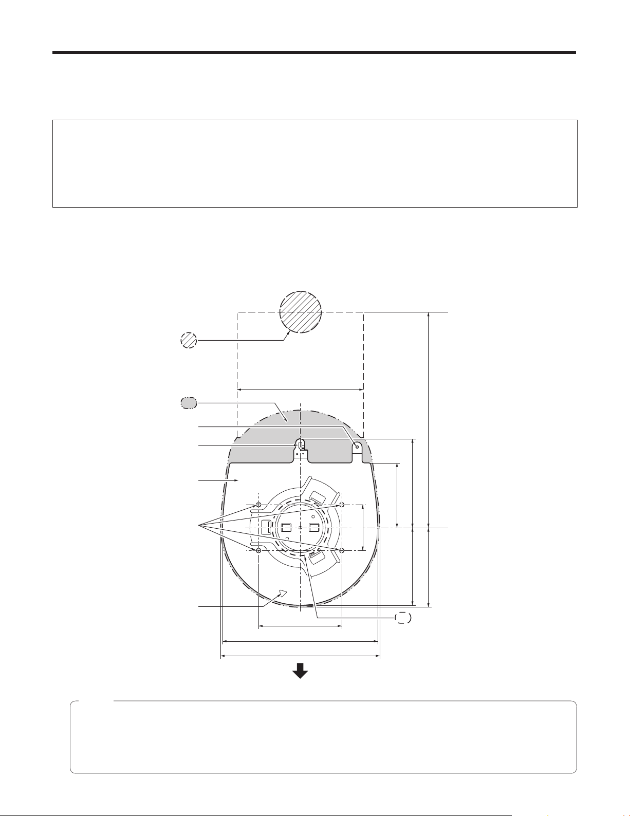
1 Check the mounting space.
Refer to the illustration, and determine where the unit is to be installed and in which direction it should be mounted.
Factor in the unit mounting area and include space for the wires extending from its rear panel.
The asterisk () in the illustration marks the position and dimensions of the hole for mounting the mount bracket.
Unit: mm (inch)
Through-hole for cable
ø 40 mm (reference)
Unit mounting area
Hole for mounting the main
unit mounting screws
Hook for mounting the
drop-prevention wire
Mount bracket
) Holes for mounting the
(
mount bracket: ø 4.5 mm 4
Hole for checking
the positioning
(Space for the wires from the
130 (5-1/8)
rear panel)
()83.5 (3-5/16)
156 (6-1/8)
160 (6-5/16)
)46 (1-13/16)
(
(Space for the wires)
290 (11-7/16) or more
65 (2-9/16)
78 (3-1/16) 90 (3-9/16)
80 (3-5/32)
Hole for installing the WV-Q105
direct ceiling mount bracket
[ø 60 mm (ø 2-3/8˝)]
The front panel of the unit on this side.
Notes
Before proceeding to install and connect the main unit, connect the LAN cable, video output cable, interface cable,
AC adapter cable and coaxial cables in the space above the ceiling panel, and then pass the cables through the cable
holes.
For a power outlet which is used on the ceiling, be absolutely sure to take measures to deal with the tracking that may
be caused by the accumulation of dust and other foreign matter.
20
Page 21
How to install and connect the unit
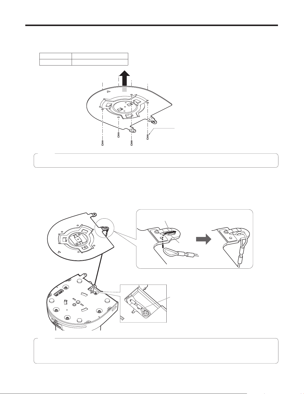
2 Mount the mount bracket onto the installation surface.
Use the bracket mounting screws (M4, bind‑head: 10 mm long) supplied with the unit.
For proper clamping torque, securely attach the screws using the specified tools.
Screw diameter Clamping torque
M4 1.47 N · m (15 kgf · cm)
Bracket mounting screws 4 (supplied)
(M4, bind-head)
Note
Use only the screws supplied with the unit. Do not use any other screws such as wood screws, nails, etc.
3 Attach the drop-prevention wire.
Pull out the drop‑prevention wire from the bottom panel of the unit, and engage the end with the wire ring through the
hole of the mount bracket hook.
Pull the drop‑prevention wire, and check that it has been attached securely to the hook.
Holding spring
End of hook
Pull out the drop-prevention wire, and
engage it with the mount bracket hook.
Drop-prevention wire
Notes
Do not do this work while holding the camera head since doing so may result in malfunctioning of the unit.
The drop‑prevention wire is designed to be used for installation where the unit is suspended from an overhead
surface so do not subject it to the weight of units other than the unit.
21
Page 22
How to install and connect the unit
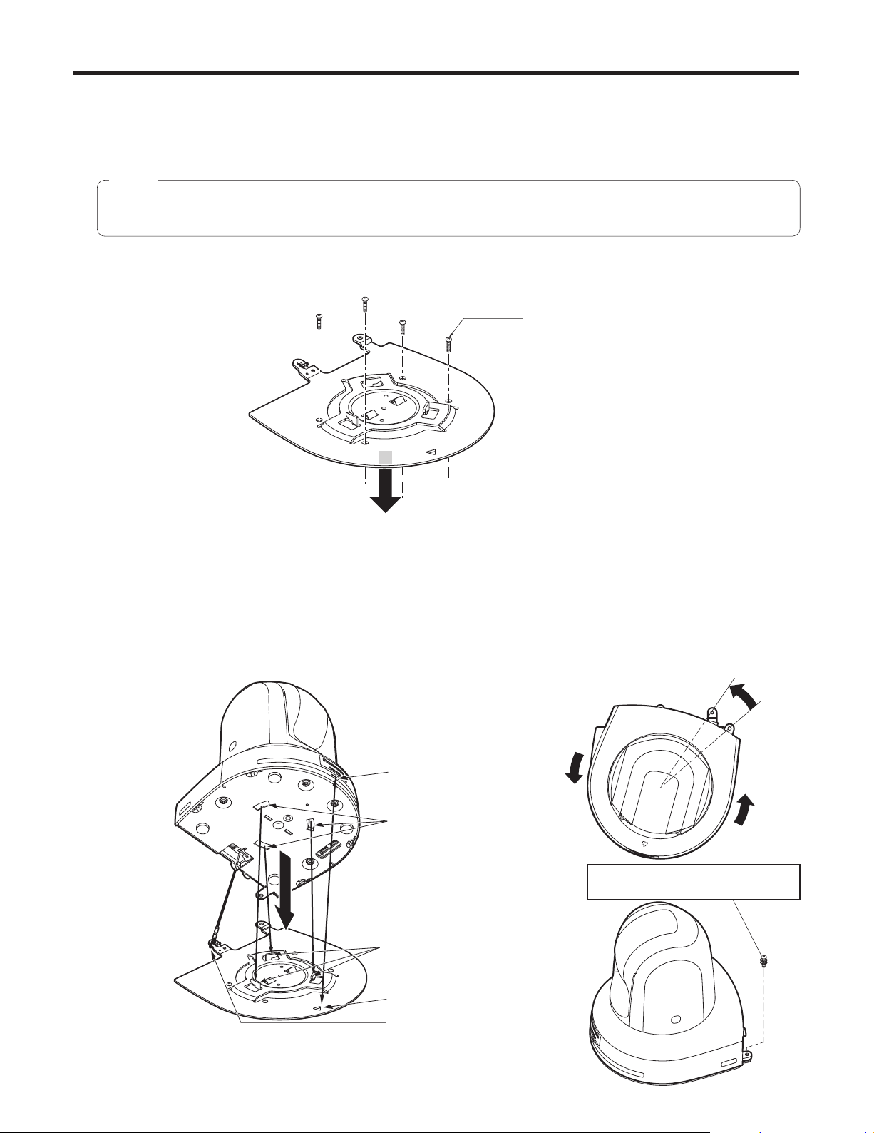
4 Mount the unit.
Align the position of the hole for checking the positioning with the status display lamp.
Align the holes on the camera main unit used to insert the bottom panel with the protrusions on the mount bracket used
for inserting the camera, push the bracket and camera firmly together, and rotate the main unit by about 15 degrees in
the direction of the arrow.
Secure the mount bracket to the unit using the main unit mounting screws (M3) as supplied.
Attach the mount bracket securely with the prescribed tool using the clamping torque below.
Be absolutely sure to verify that none of the screws are loose.
Screw diameter Clamping torque
M3 0.78 N · m (8 kgf · cm)
Hole for checking
the positioning
On the mount
bracket: Protrusions
(3) used for
inserting the camera
Approx.
15°
On the camera
main unit: Holes
(3) used to insert
the bottom panel
Status display lamp
Notes
Do not do this work while holding the camera head since doing so may result in malfunctioning of the unit.
Use only the screws supplied. Do not use any other screws.
Check that the unit has been mounted securely with no tilting or wobbling.
5 Check the mounting.
Check out the following points.
• The main unit mounting screws must be mounted securely.
• The unit must not tilt, and it must be mounted exactly.
• The unit must be securely installed.
• The unit pedestal part must not rotate even when an attempt is made to turn it.
Main unit mounting screw (M3 screw)
(with flat washer, spring washer)
22
Page 23
How to install and connect the unit
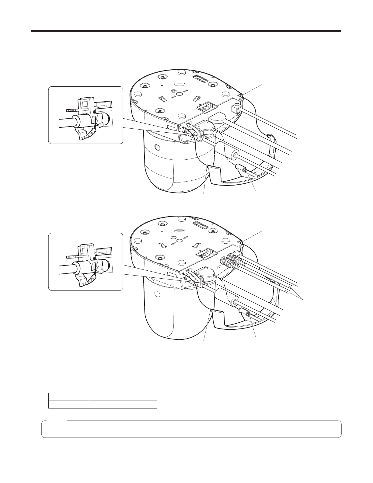
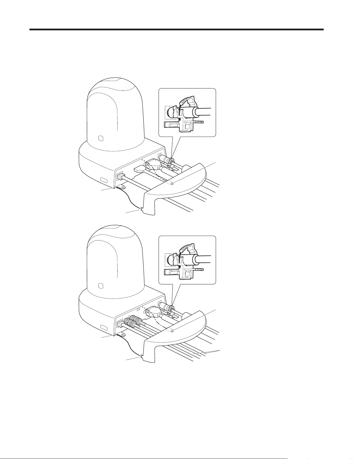
6 Connect the rear panel connectors.
Anchor the AC adapter cable in place using the cable clamp.
[AW-HE50H]
Cable clamp
Square hole (one at either side)
LAN cable
Video output cable
Interface cable
AC adapter cable
Tab (one at either side)
[AW-HE50S]
Cable clamp
Tab (one at either side)
7 Attach the cable cover.
Fit the two tabs on the cable cover into the square mounting hole at either side of the rear panel.
Secure the cable cover using the screw (M3 20 mm) provided.
Screw for cable cover (M3 screw)
(with flat washer, spring washer)
Square hole (one at either side)
LAN cable
Coaxial cables
Interface cable
AC adapter cable
Screw for cable cover (M3 screw)
(with flat washer, spring washer)
Screw diameter Clamping torque
M3 0.78 N · m (8 kgf · cm)
Note
Engage the tabs on the cable cover so they fit into place perfectly, and check that the cover is not rickety.
23
Page 24
How to install and connect the unit
When using the WV-Q105 (optional accessory)
It is recommended that you provide an inspection opening or other such space for access purposes in the area near where the
equipment is installed in order to facilitate installation and the wiring connections work.
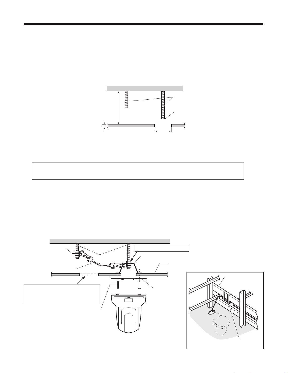
Before mounting the mount bracket, check that the installation location is strong enough to withstand the total mass
(approx. 2.0 kg [4.41 lbs.]) which will be exerted once the camera is mounted.
Use the mount bracket where the space between the ceiling panel and the concrete ceiling is at least 100 mm high.
The bracket can be mounted where the thickness of the ceiling panel ranges from 5 mm to 40 mm.
The drop‑prevention wire (supplied with the WV‑Q105) must be used when mounting the direct ceiling mount bracket.
Concrete ceiling
Anchor bolts
Height above ceiling
panel: At least 100 mm
Ceiling panel (plasterboard, etc. with
a thickness from 5 mm to 40 mm)
ø 60 mm
1 Refer to the Operating Instructions of the WV-Q105 direct ceiling mount bracket, and attach the
WV-Q105 as well as the drop-prevention wire angle and drop-prevention wire supplied with the WV-Q105
to the anchor bolts.
Withdrawal strength: 196 N (20 kgf) or more
The anchor bolts must not protrude
beneath the ceiling panel.
Mounting the anchor bolts and direct ceiling mount bracket ()
This job is facilitated if the direct ceiling mount bracket is loosely secured to the ceiling panel in one place, and
the direct ceiling mount bracket and anchor bolts are vertically aligned before the nuts are tightened up.
2 First, remove the screws which were loosely fastened in step 1, and then align the camera mount
bracket of the AW-HE50 with the screw holes in the WV-Q105 direct ceiling mount bracket and mount it
in place.
Use the mounting screws (the M4‑L60 Phillips head screws with adhesive) supplied with the WV‑Q105 as the mounting
screws.
Fasten the AC adapter securely to the bottom or other surface of the reinforcing member made of channel steel where
dust and other foreign matter will not accumulate.
Do not place the AC adapter directly onto the ceiling panel or other such surface.
Space above the ceiling
Drop-prevention wire
angle (Supplied with
WV-Q105)
Drop-prevention wire
(Supplied with WV-Q105)
Inspection opening recommended
The installation and wiring connection
work is facilitated if an inspection
opening is provided for access purposes.
Anchor bolts
(): Fasten here using the nut.
Direct ceiling mount bracket WV-Q105 (optional accessory)
Plasterboard or other ceiling panel
Channel steel
Camera mount
bracket (Supplied
with AW-HE50)
Mounting screw 4
(Supplied with WV-Q105)
AW-HE50
3 Attach the AW-HE50 to the mount bracket.
( Ceiling
panel)
Secure the AC adapter firmly to a
member made of channel steel.
24
Page 25
Changing the direction of the nameplate
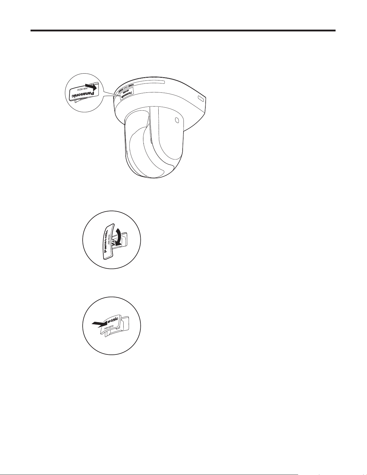
When the unit is mounted on the ceiling, its nameplate will be upside down.
The direction of the unit’s nameplate can be changed.
1 Push in the part indicated by the arrow, and pull out the nameplate.
2 Change the direction of the nameplate.
3 Push the nameplate back into place.
25
Page 26
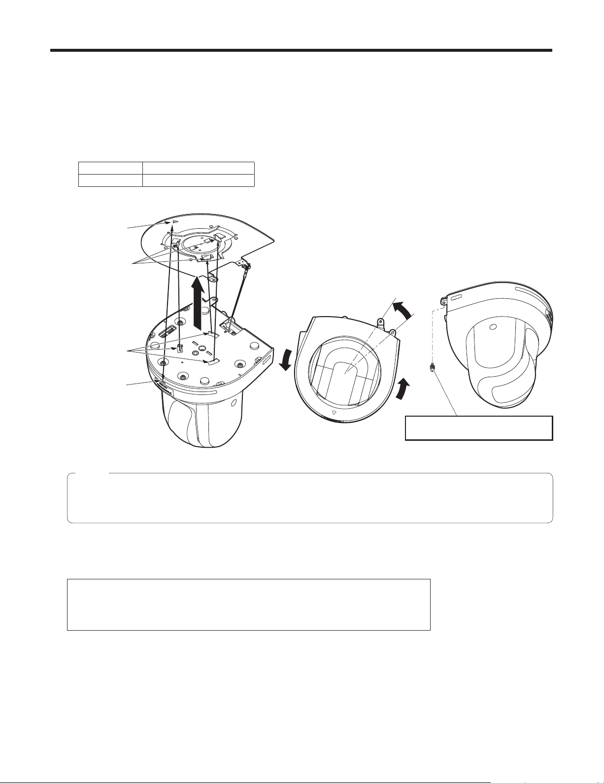
Removing the camera
1 Turn off the circuit breaker and power.
2 Remove the cable cover.
Remove the screw (M3) for the cable cover used to secure the cover.
Push the tab parts of the cover to disengage the cover.
3 Disconnect the cables.
Disconnect the power cable, video cable, and control cable, etc.
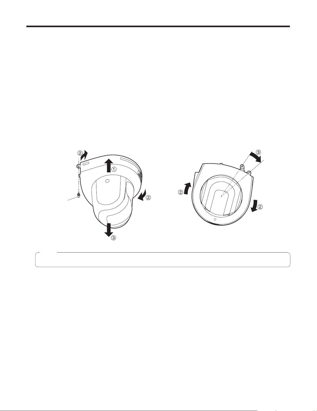
4 Remove the main unit mounting screw used to secure the unit and mount bracket.
5 Push the unit (1). Turn it approximately 15 degrees away from the installed position (2),
and remove it (3).
Approx.
15°
Main unit mounting
screw (M3 screw)
(with flat washer,
spring washer)
Note
Do not do this work while holding the camera head since doing so may result in malfunctioning of the unit.
6 Disengage the drop-prevention wire from the mount bracket.
26
Page 27
Stand-alone installation (when the mount bracket is going to be used)
The same steps are followed as for the kind of installation where the unit is suspended from an overhead surface
(pages 20 to 23).
1 Check the mounting space.
Note
As with installing the unit suspended from an overhead surface, carefully check the space where the unit will be
mounted, and then decide if it is appropriate to install the unit in that space.
2 Mount the mount bracket onto the installation surface.
Bracket mounting screws 4 (supplied)
(M4, bind-head)
3 Attach the drop-prevention wire.
4 Mount the unit.
Align the position of the hole for checking the positioning with the status display lamp.
Align the holes on the camera main unit used to insert the bottom panel with the protrusions on the mount bracket used
for inserting the camera, push the bracket and camera firmly together, and rotate the main unit by about 15 degrees in
the direction of the arrow.
Secure the mount bracket to the unit using the main unit mounting screws (M3) as supplied.
For proper clamping torque, securely attach the screws using the specified tools.
Status display lamp
On the camera main unit:
Holes (3) used to insert
the bottom panel
Main unit mounting screw (M3 screw)
(with flat washer, spring washer)
On the mount bracket:
Protrusions (3) used for
inserting the camera
Approx.
15°
Hole for checking the
positioning
Attach the drop-prevention
wire.
27
Page 28
Stand-alone installation (when the mount bracket is going to be used)
5 Check the mounting.
6 Connect the rear panel connectors.
[AW-HE50H]
Cable clamp
Screw for cable cover (M3 screw)
(with flat washer, spring washer)
Square hole (one at either side)
Tab (one at either side)
[AW-HE50S]
Square hole (one at either side)
AC adapter cable
Interface cable
Video output cable
LAN cable
Cable clamp
Screw for cable cover (M3 screw)
(with flat washer, spring washer)
AC adapter cable
Interface cable
Coaxial cables
Tab (one at either side)
7 Attach the cable cover.
LAN cable
28
Page 29
Stand-alone installation (when the mount bracket is not going to be used)
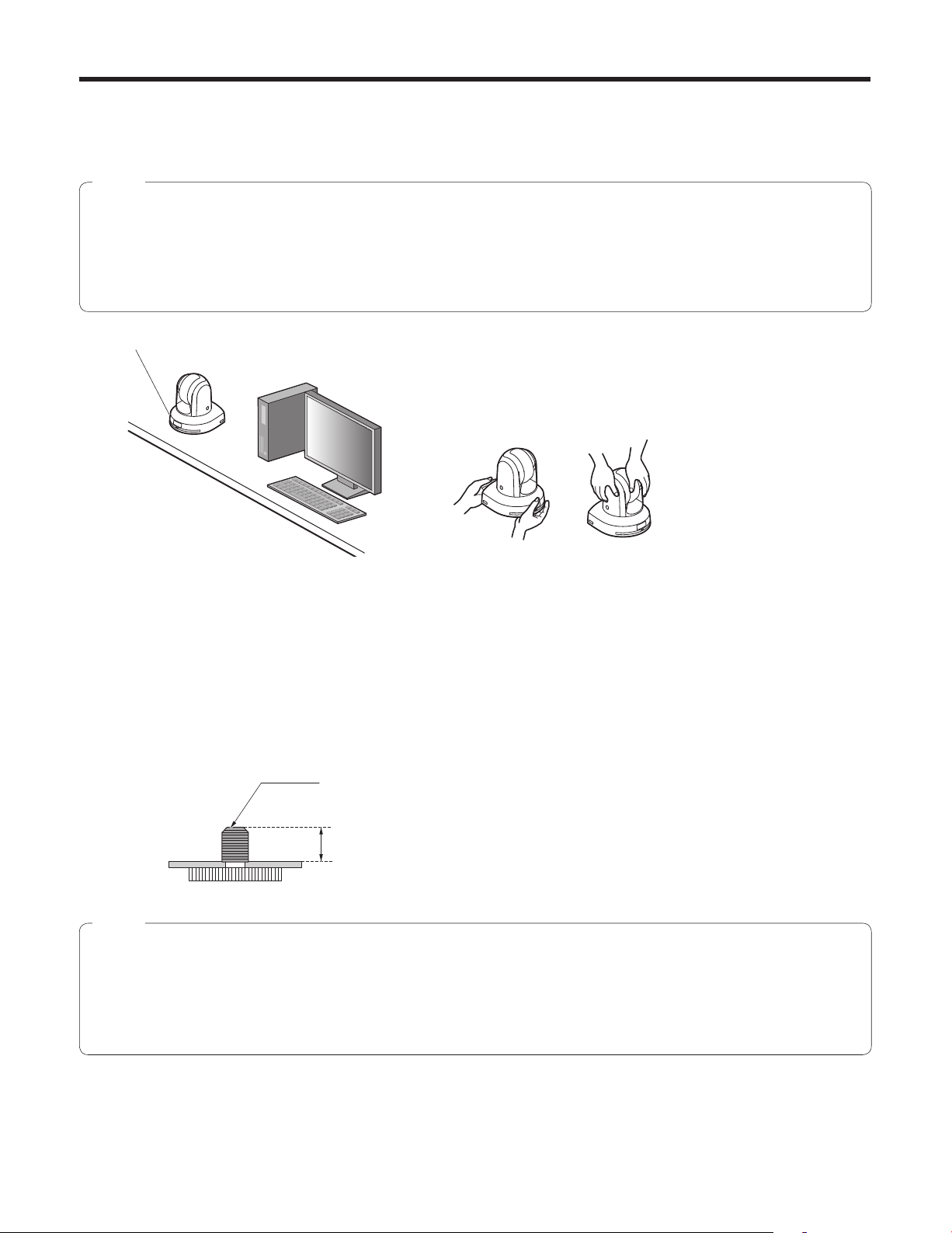
When installing the unit on a desktop
Place the unit flat on the surface.
Notes
Install the unit in a stable location which will not be susceptible to shaking. If the unit is installed in a location which is
susceptible to shaking, this will cause the unit’s images to shake in turn.
Take care not to allow the unit to fall or otherwise be damaged during installation.
When carrying the unit, do not hold it by its head.
Do not take hold of the camera head or rotate it. Doing so may cause malfunctioning.
Take care not to pull the connected cables. Doing so may cause the unit to fall and/or it may result in injury.
Ensure that the unit will not fall off.
OK NG
When mounting the unit on a tripod
Attach the tripod to the threaded holes for mounting the camera on the camera’s bottom panel.
Place the tripod on a completely flat and level surface.
Tighten the screws by hand to mount the tripod securely.
Use screw for mounting the tripod that satisfy the following standard.
Screw for mounting tripod (1/4-20UNC)
4.5 mm to 6 mm
(0.18 to 0.24 inches)
Notes
Do not install the unit where people will be passing back and forth.
When using the unit mounted on a tripod, do not put the tripod high above the floor level.
Mount the unit securely so there is no looseness. Looseness may cause the unit to fall off and/or result in injuries.
When the unit is going to be used for a prolonged period of time, take steps to ensure that the unit will not topple or fall
over and that it will not fall off or fall down. After using the unit, restore the installation location to its original state without
delay.
29
Page 30
Connections
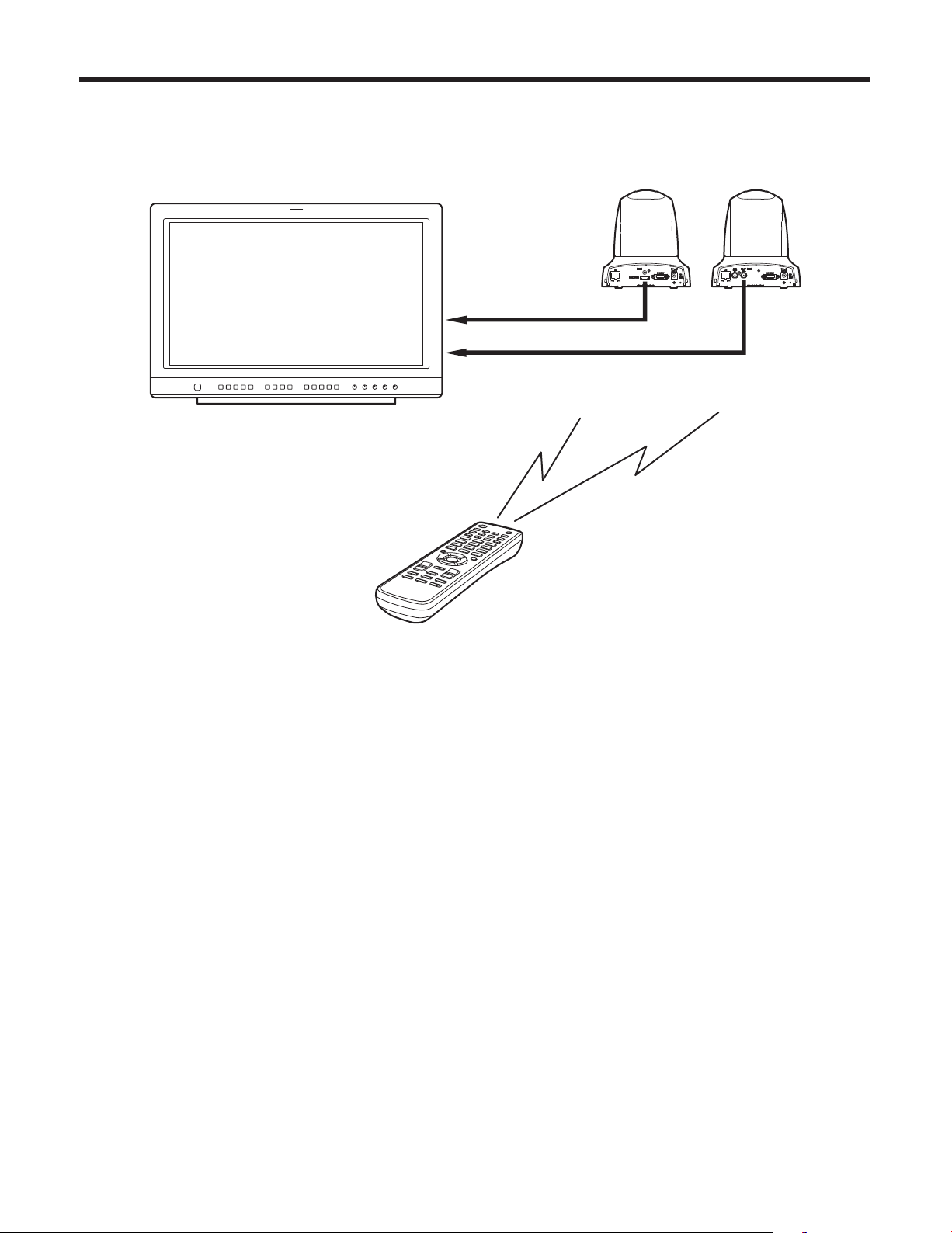
Connections with an HD monitor
HD monitor
HD Integrated Camera
AW-HE50
HDMI signal (AW-HE50H only), SDI signal (AW-HE50S only)
or HD analog component signal
Wireless remote control (optional accessory)
Up to four units can be operated using one remote control.
30
Page 31

Connections
Connections with a controller (AW-RP655 or AW-RP555)
LAN cable (straight cable)
Multi Hybrid
Control Panel
AW-RP555
Multi-Function Controller
AW-RP655
Pan-tilt head/
camera control signals
AC Adapter
AW-PS510A
RJ-45 relay
adapter
AC Adapter
AW-PS510A
HD Integrated Camera
AW-HE50
OUT
IN
V
PR
PB
Y
Multi-Interface
Cable
AW-CA20T6
HDMI/SDI video signal
Monitor
Accessory AC adapter
31
Page 32

Connections
System example 1
Genlock signal
generator
SDI video signal
HD Integrated Camera
AW-HE50S
Accessory
AC adapter
Switcher
Monitor 1
System TALLY
HD Integrated Camera*
AW-HE50S
Pan-tilt head and
camera control signal
Monitor 2
Monitor Monitor
AC Adapter
AW-PS510A
SDI output is supported only by the AW‑HE50S.
Multi-Function Controller
AW-RP655
*: The AC adapter provided with the unit is
not shown in the above figure.
32
Page 33

Connections
System example 2
Genlock signal
generator
SDI video signal
HD Integrated Camera
AW-HE50S
Accessory
AC adapter
HD Integrated Camera*
AW-HE50S
LAN cable
(straight cable)
Monitor 2
Switching hub
Monitor 1
LAN cable
(straight cable)
Compact Live Switcher
AW-HS50
SDI output is supported only by the AW‑HE50S.
Monitor Monitor
Remote Camera Controller
AW-RP50
*: The AC adapter provided with the unit is
not shown in the above figure.
33
Page 34

Network settings
Installing the software
Be absolutely sure to read through the “Readme.txt” on the
CD‑ROM supplied with the unit first before attempting to
install the software.
Software provided on the CD-ROM
Easy IP Setup Software (EasyIPSetup.exe)
This software establishes the unit’s network settings.
For details, refer to the sections that follow.
Use the Easy IP Setup Software
to establish the unit’s settings
The settings related to the unit’s network can be established
using the Easy IP Setup Software supplied.
To establish the settings for a multiple number of units, the
settings must be selected for each camera involved.
If the settings cannot be established using the Easy IP
Setup Software, select the settings separately for the unit
and PC on the network page of the setting menu. For further
details, refer to the “Operating Instructions — <Operations
and Settings>” (PDF file).
If the Easy IP Setup Software is run when using
Microsoft
important warning screen concerning security may
appear.
If this is the case, click the [Unblock(U)] button.
If the Easy IP Setup Software is run when using
Microsoft
enter the password for the Administrator account.
If this is the case, disable “User Account Control” from
Control Panel.
The Easy IP Setup Software is designed in such a way
that when around 20 or more minutes have passed
after the power was turned on, the MAC address and IP
address of the target camera will no longer be displayed.
It does this to improve the security.
When “20min” is selected for the enable time among
The Easy IP Setup Software cannot be used from a
different subnet via a router.
The unit cannot be displayed or its settings established
using an older version of the Easy IP Setup Software
(Ver.2.xx).
®
Windows® XP Home Edition SP3, an
®
Windows Vista®, you may be prompted to
the Easy IP Setup accommodate period. (page 70 in
the <Operations and Settings>)
34
Page 35

Network settings
1 Start the Easy IP Setup Software.
2 Click the MAC address/IP address of the
camera to be set, and click the [IP setting]
button.
Notes
When a DHCP server is being used, the IP
address allocated to the unit can be checked by
clicking the [Refresh] button of the Easy IP Setup
Software.
If IP addresses are in contention, the MAC
address of the camera concerned is the one
shown with the shading.
After the [Apply] button is clicked, it takes about
2 minutes for the settings in the unit to be completed.
If the AC adapter or LAN cable is disconnected
before the settings are completed, the settings will be
canceled. In this case, repeat the steps to establish
the settings.
When a firewall (including software) has been
introduced, enable access to all the UDP ports.
3 Input the network items, and click the [Apply]
button.
Note
When a DHCP server is being used, “DNS” of the
Easy IP Setup Software can be set to “AUTO”.
35
Page 36

Troubleshooting
Operation
Symptom Cause and remedial action
No power
Cannot operate
( common to wireless
remote control,
controller)
Reference
pages
Is the AC adapter securely connected to the AC outlet? –––
If the power plug of the AC adapter connected properly? –––
If the unit is connected to the controller, has it been connected
properly?
Refer to the Operating Instructions of the controller.
When the unit is being operated by the wireless remote control
Also refer to the “Cannot operate using the wireless remote control”
item.
Is the power on?
If the unit’s status display lamp is off or if it has lighted up orange,
it means that the unit’s power is not being supplied.
The safe mode function may have been activated.
Have the limiter functions been set?
P.31 to 33
<Operations and
Settings>
<Operations and
Settings>
<Operations and
Settings>
P.81 to 82
–––
P.7
P.83
Cannot operate using
the wireless remote
control
Cannot operate using
the controller
The unit turns in the
opposite direction to
the one operated
Has the correct unit to be operated been selected?
Have the remote control’s batteries run down or have the batteries
been installed with their polarities reversed?
If the status display lamp does not blink even when the wireless
remote control is operated near the wireless remote control signal
light‑sensing area, it means that the batteries have run down.
Replace the batteries.
Is there a fluorescent light or plasma monitor near the unit and,
if so, is the wireless remote control signal light-sensing area
exposed to its light?
Is the unit connected to the controller properly?
Refer to the Operating Instructions of the controller.
It may be necessary to upgrade the version of the controller so
that the controller will support the unit.
Consult with your dealer.
Has the stand-alone (Desktop) installation setting been selected
correctly?
The reversal setting may have been established at the controller if
the unit is connected to the controller.
Refer to the Operating Instructions of the controller.
<Operations and
Settings>
P.9
–––
P.14
P.31 to 33
–––
<Operations and
Settings>
P.46, P.65
–––
36
Page 37

Troubleshooting
Symptom Cause and remedial action
The adjustment of
the slowest speed
at which the camera
is to start panning
and tilting fails to
be completed for
the AW-RP655 or
AW-RP555
Do not attempt to adjust the slowest speed at which the camera is to
start panning and tilting since this adjustment does not need to be
undertaken when the unit is connected with the AW-HE50.
If an attempt is made to undertake this adjustment, the following will
occur:
When the AW-RP655 is used:
The LCD will keep showing that adjustment is still underway for
the right side of the slowest start speed for panning and tilting,
and it will not be possible to transfer to the next adjustments (top
left bottom).
Press the [MENU] button to cancel the adjustment of the slowest
speed at which the camera is to start panning and tilting.
When the AW-RP555 is used
The lamps of the [MEMORY] button and [MODE] button will not
stop blinking.
Operate the joystick, and cancel the adjustment of the slowest
speed at which the camera is to start panning and tilting.
Has a LAN cable of category 5 or above been connected to the
LAN connector for IP control?
Is the [LINK] LED of the LAN connector for IP control lighted?
If it is not lighted, it means that something is wrong with the
connection to the LAN or that the network at the connection
destination is not working properly.
Check the LAN cable for defective contacts, and check the wiring.
Reference
pages
–––
P.31 to 33
P.31 to 33
The web setting
screen cannot be
accessed
Is the power on?
If the unit’s status display lamp is off or if it has lighted up orange,
it means that the unit’s power is not being supplied.
Has a valid IP address been set in the unit?
Has the wrong IP address been accessed?
Check the connections by following the steps below.
Using the Windows command prompt:
> ping [IP address which has been set in the camera]
A reply returned from the unit signifies that there are no problems in
operation.
If a reply is not received, try following operation:
• Reboot the unit, and within 20 minutes change the IP address
using the Easy IP Setup Software.
Has 554 been set as the HTTP port number?
Use any port number, except for the numbers below which are used
by the unit, for the HTTP port number.
20, 21, 23, 25, 42, 53, 67, 68, 69, 110, 123, 161, 162, 554, 995,
10669, 10670, 59000 to 59999, 60000 to 61000
<Operations and
Settings>
P.7
<Operations and
Settings>
P.69 to 70
–––
<Operations and
Settings>
P.70
37
Page 38

Troubleshooting
Symptom Cause and remedial action
The web setting
screen cannot be
accessed
Has the same IP address setting been used for another device?
Is there a lack of consistency between the address set and the
network subnet at the installation destination?
[When the personal computer is connected to the unit within the
same subnet]
Have the IP addresses of the unit and personal computer been
set to the subnet shared by the unit and computer? Has the
“Use proxy server” setting been selected by the web browser?
When accessing the unit within the same subnet, it is
recommended that the unit’s address be set to the “Remove
from proxy” address.
[When the unit and personal computer are connected to different
subnets]
Has the wrong setting been selected as the default gateway
setting for the unit?
Press the [F5] key on the keyboard of the personal computer to
request that the settings be acquired.
Follow the steps below to delete the temporary Internet files.
1 In Internet Explorer, select [Tools] [Internet Options].
2 Click the [Delete] button for “Temporary Internet files”.
Reference
pages
–––
<Operations and
Settings>
P.70
–––
–––
The settings on the
web setting screen
are not updated or
displayed properly
It is not possible to
download the setting
files
If, in the Temporary Internet Files settings, the check “Every time
I visit the webpage” setting is not selected for “Check for newer
versions of stored pages”, the web setting screen may not be
displayed properly.
Follow the steps below.
1 In Internet Explorer, select [Tools] [Internet Options].
2 When Internet Explorer 7.0 is being used:
Click the [Settings] button in “Browsing history”, and select
“Every time I visit the webpage” under “Check for newer
versions of stored pages”.
When Internet Explorer 6.0 is being used:
Click the [Settings] button in “Temporary Internet files”,
and select “Every visit to the page” under “Check for newer
versions of stored pages”.
The unit’s ports may be filtered by the firewall or other function of
the anti-virus software.
Change the HTTP port number of the unit to a port number which
will not be filtered.
Has the file download function been disabled?
On the “Security” settings screen (Internet Options Security) of
Internet Explorer, click the “Custom Level” button under “Security
level for this zone” to enable “File download” and “Automatic
prompting for file downloads”.
–––
–––
–––
38
Page 39

Troubleshooting
Video
Symptom Cause and remedial action
No pictures are
displayed or the
pictures are disturbed
The picture is flipped
vertically
Multiple color bands
(color bars) are
displayed
The menu screen is
displayed
Has the unit been connected properly to the other connected
devices?
If the system is configured in such a way that the picture is also
switched when the unit to be operated is selected, has the correct
unit been selected?
Has the video signal setting been selected correctly?
Has the stand-alone (Desktop) installation setting been selected
correctly?
Switch to the camera picture.
Exit the menu.
Reference
pages
P.30 to 33
<Operations and
Settings>
P.9
<Operations and
Settings>
P.43, P.64
<Operations and
Settings>
P.46, P.65
<Operations and
Settings>
P.13
<Operations and
Settings>
P.30 to 37
It is difficult to view
the menu screens
No auto focusing
The subject is not
brought into focus
during zooming when
the manual setting is
used for the focus
Depending on the HDMI monitor you are using, you may
experience one or more of the symptoms described below. These
symptoms are especially noticeable when any of the SD formats
is used: This is normal and not indicative of any trouble.
• The resolution of the characters in the menu displays changes as the
background image changes.
• Depending on the edge enhancement setting established for the
monitor, white lines appear in front of the black shadows of the
menus.
• Depending on the edge enhancement setting established for the
monitor, the background colors may be superimposed onto the white
parts of the menus.
Is the focus set to manual?
Auto focusing is initiated as soon as the focus is set to auto.
In some situations, it may be hard to focus at the auto setting.
In cases like this, select the manual setting, and focus manually.
Was the focus adjusted at the Tele end?
First adjust the focus at the Tele end where the focusing accuracy is
higher, and then proceed with the zooming.
Under some operating conditions, it may be hard to bring
subjects into focus.
In such cases, use the focus at the auto setting.
–––
<Operations and
Settings>
P.13
<Operations and
Settings>
P.15
–––
<Operations and
Settings>
P.13
39
Page 40

Troubleshooting
Symptom Cause and remedial action
Ring-shaped
reflections appear
in the four corners of
the images
Something is wrong
with the coloring of
the pictures
The pictures are too
light or too dark
The subjects appear
distorted
These are caused by the reflections of the light between the lens
and the cover in front of the lens. Find a way of optimizing the
position of the lighting relative to the position of the unit, and
install and use the unit in a location where the reflections will not
occur.
Activate the ATW (Auto tracking white adjustment) function.
In some situations, the proper colors may not be reproduced
using the ATW function.
In cases like this, proceed with the white balance adjustment.
Either select the auto setting for the iris or select the manual
setting and adjust the iris manually.
The pictures may be dark if the video signal cables are too long
because this will cause signal attenuation.
If a subject has suddenly crossed in front of the camera, it may
appear slightly distorted because this camera uses a MOS image
sensor.
This is normal and not indicative of any problem.
Reference
pages
–––
<Operations and
Settings>
P.24
<Operations and
Settings>
P.22 to 24
<Operations and
Settings>
P.16
–––
–––
When the flash is fired
during shooting, only
the top or bottom of
the screen becomes
lighter
The brightness
changes cyclically or
the colors change,
and horizontal stripes
can be seen passing
across the screen
When fine lines or
cyclical patterns are
shot, flickering is seen
or coloring is added to
them
With a MOS image sensor, the shooting timing differs slightly
between the top left and bottom right of the screen. This means
that when the flash is fired, the bottom of the screen will become
lighter in the field concerned and the top will become lighter in
the next field.
This is normal and not indicative of any problem.
These phenomena (flicker) may occur under the illumination
produced by fluorescent lighting, mercury bulbs or other types of
discharge tubes.
This is normal and not indicative of any problem.
At a time like this, it is recommended that the electronic shutter
speed be set to 1/100 in areas with a 50 Hz power line frequency
or to OFF in areas with a 60 Hz power line frequency.
This phenomenon occurs because the pixels are arranged
systematically on each image sensor. It is noticeable when the
spatial frequency of a subject and the pixel pitch are brought into
proximity so change the camera angle or take other such action.
–––
–––
–––
40
Page 41

Troubleshooting
Web settings
Depending on the OS installed on the PC, the following may occur. Follow the instructions below when the following has
occurred. By performing the following solutions, other applications and the security level may not be affected.
The “Information bar” expressed in the following symptom and solutions will be displayed just below the address bar only when
there is information to communicate.
Symptom Cause and remedial action
The following message
is displayed on the
information bar.
“Pop-up blocked. To see
this pop-up or additional
options click here.”
An unnecessary status
bar or scroll bar is
displayed on the pop-up
window
Click the information bar and select “Always Allow Pop-ups
from This Site”. The dialog window saying “Allow pop-ups
from this site?” will be displayed.
Click the [Yes] button.
Click “Internet Options” under “Tools” of the menu bar of
Internet Explorer
Click “Internet” in the “Select a Web content zone to specify
its security settings:” section. Then, click the [Custom Level...]
button to open the “Security Setting” window.
Under “Miscellaneous”, select “Enable” for “Allow scriptinitiated windows without size or position constraints”.
Click the [OK] button.
When the warning window is displayed, click the [Yes] button.
®
, and then click the [Security] tab.
Reference
pages
–––
–––
41
Page 42

Appearance
R80
(R3-5/32)
Unit: mm (inch)
85 (3-11/32)
175 (6-7/8)
123 (4-13/16)
160 (6-5/16)
3 (1/8) 55 (2-3/16)
80 (3-5/32) 72 (2-13/16)
166 (6-9/16)
AW-HE50H
AW-HE50S
42
Page 43

Specifications
Power requirements: DC 12 V 10 %
(AC adapter provided)
Power consumption: DC 12 V, 1.2 A (AW‑HE50H)
DC 12 V, 1.3 A (AW‑HE50S)
indicates safety information.
GENERAL
Ambient operating temperature:
0 °C to +40 °C (32 °F to +104 °F)
Storage temperature: –20 °C to +50 °C (–4 °F to +122 °F)
Allowable humidity ranges:
20 % to 90 % (no condensation)
Mass: Approx. 1.4 kg (3.09 lbs.)
Dimensions (W D H):
160 166 178 mm
(6‑5/16˝ 6‑9/16˝ 7˝)
[excluding protrusions, cable cover,
direct ceiling mount bracket]
Finish: Light silver matte finish
Controller supported: AW‑RP655, AW‑RP555, AW‑RP50
It may be necessary to upgrade
the version of the controller so
that the controller will support the
unit.
INPUT
Input connector: DC 12 V IN,
EXT SYNC IN (BNC)
(AW‑HE50S only)
BBS (Black Burst Sync) signal
supported
OUTPUT
Video output:
[AW-HE50H] HDMI: HDMI connector
[AW-HE50S] SDI: Compliant with the SMPTE292M/
SMPTE259M standards/75
(BNC 1)
[ Specifications
common to
both models]
Y/Pr/Pb
Composite: 1.0 V [p‑p]/75
(MULTI‑I/F 1)
[HD] Y: 1.0 V [p‑p]/75 ,
Pr
·
Pb: 0.7 V [p‑p]/
75 (MULTI‑I/F 1)
[SD] Y: 1.0 V [p‑p]/75 ,
Pr
·
Pb: 0.7 V [p‑p]/
75 (MULTI‑I/F 1)
For Y/Pr/Pb, the 1080, 720 or SD format is selected
depending on the format setting.
INPUT/OUTPUT
Input/Output connector: LAN connector for IP control
(RJ‑45)
CONTROL IN RS422A
(MULTI‑I/F)
43
Page 44

Specifications
FUNCTIONS AND PERFORMANCE
[Camera unit]
Imaging sensors: 1/3˝ Full‑HD MOS
Lens: Motorized 18 zoom, f/1.6 to 2.8
(f=4.7 to 84.6 mm; 35 mm
equivalent: 36.9 mm to 664.5 mm)
Focus: Switching between auto and manual
Focus distance: Entire zooming range:
1.5 m (4.9 ft.)
Wide end: 30 cm (0.98 ft.)
Color separation optical system:
On‑chip color filter system
Minimum illumination: 3 lx (50 IRE, F1.6, +36 dB)
Horizontal resolution: 850 TV lines Typ (Center area)
Gain selection: Auto, 0 dB, 3 dB, 6 dB, 9 dB, 12 dB,
15 dB, 18 dB
Storage mode: 0 dB, 6 dB, 12 dB, 18 dB
Electronic shutter speed:
1/100, 1/250, 1/500, 1/1000,
1/2000, 1/4000, 1/10000
Synchro scan: 60.24 Hz to
646.21 Hz
Gamma: Off, Normal (Low, Mid, High),
Cinema
White balance: AWB A, AWB B, ATW
Chroma amount variability:
7 levels variability
Scene file: FullAuto, Manual1, Manual2,
Manual3
Color bars: FULL BAR
Output format: HD 1080: 59.94i,
720: 59.94p
SD 480: 59.94i
Synchronization system:
[AW‑HE50H]
Internal synchronization
[AW‑HE50S]
Internal/External synchronization
(BBS)
[Pan-tilt head unit]
Installation method: Stand‑alone (Desktop) or
suspended (Hanging)
To ensure safety, the unit must be
secured using the mount bracket
provided.
Camera/pan-tilt head control:
IP connecting
cable
RP connecting
cable
Protocol RS‑422A, AW series protocol
*: Use of an STP (shielded twisted pair) cable is
recommended.
Pan/tilt operation speed:
Max. 90°/sec. or more
Panning range: ±175°
Tilting range: +90° to –30°
Quietness: NC35 (normal speed),
When connecting through a hub:
LAN cable* (category 5 or above,
straight cable), max. 100 m (328 ft.)
When a hub is not used:
LAN cable* (category 5 or above,
crossover cable) max. 100 m (328 ft.)
LAN cable* (category 5 or above,
straight cable), max. 1000 m (3280 ft.)
( Control only: Use of an external device
or some other means must be provided
separately in order to extend the video
signal connections.)
Depending on the pan or tilt
position, the camera may be
reflected in the image.
NC40 (when preset)
AC adapter
Input: AC 100 V to 240 V, 1.5 A, 50/60 Hz
Output: DC 12 V, 2.5 A, 30 W
The provided power cable is for 125 V AC or less.
Use it within AC 100 V to 120 V.
Optional accessories
Wireless remote control AW-RM50G
(Size “AA” dry battery 2, obtained separately)
Direct ceiling mount bracket WV-Q105
Multi-interface cable AW-CA20T6G
Mass and dimensions shown are approximate.
Specifications are subject to change without notice.
44
Page 45

Memo
Page 46

Panasonic Solutions Company
3 Panasonic Way, Secaucus, NJ 07094 Tel: 877‑803‑8492
www.panasonic.com/broadcast e‑mail: MediaProServices.PSC@us.panasonic.com
Panasonic Canada Inc.
5770 Ambler Drive, Mississauga, Ontario L4W 2T3 Tel: 905‑624‑5010
Panasonic de México S.A. De C.V.
Casa Matriz: Felix Cuevas No. 6 Pisos 2 y 3 Col. Tlacoquemecatl Del Valle Del.Benito Juárez México, D.F., C.P.03200
Tel: 55‑5488‑1000 Fax: 55‑5575‑6763
Panasonic Latin America, S.A.
P.O.Box 0816‑03164 Panama, Republic of Panama Tel: +507‑229‑2955 Fax: 507‑229‑5352
Panasonic do Brasil Ltda.
Rua Cubatão, 320‑8 andar‑Paraíso CEP 04013‑001‑ São Paulo ‑ SP Tel: (11)3889‑4000 Fax: (11)3889‑4107
© Panasonic System Networks Co., Ltd. 2010
Printed in Japan
F0410S1050
D
Page 47

Operating Instructions
<Operations and Settings>
HD Integrated Camera
Model No. AW‑HE50HN
AW‑HE50SN
3TR006484AAA
Page 48

Contents
Before use ......................................................................... 3
Overview ........................................................................ 3
Concerning the Operating Instructions .......................... 3
Required personal computer environment ..................... 4
Trademarks and registered trademarks ......................... 4
Copyrights ...................................................................... 4
Disclaimer ...................................................................... 5
Network‑related precautions .......................................... 5
Basic shooting operations .............................................. 6
How to turn the power on and off ................................... 7
Turning the power on ..................................................... 7
Turning the power off ..................................................... 8
Selecting the units ............................................................ 9
Selecting the shooting modes (scene files) ................... 9
Types of shooting modes ............................................... 9
How to select the shooting mode ................................. 10
Shooting .......................................................................... 12
What to do when encountering problems
in the basic shooting operations .............................. 13
More advanced operations ............................................ 14
Manual shooting ............................................................. 15
Manually adjusting the focus ........................................ 15
Manually adjusting the iris ............................................ 16
Manually adjusting the shutter speed .......................... 17
Manually adjusting the gain ......................................... 18
Preset memories ............................................................. 19
White balance adjustment ............................................. 22
White balance adjustment ............................................ 22
Black level (master pedestal) adjustment .................... 25
Black level (master pedestal) adjustment ..................... 25
Genlock adjustment (AW‑HE50S only) ......................... 27
Genlock adjustment ..................................................... 27
Basic operations ............................................................. 30
When performing the operations
using the wireless remote control ....................... 32
Control exercised from the Multi‑Function
Controller AW‑RP655 .......................................... 33
Control exercised from the Multi Hybrid
Control Panel AW‑RP555 .................................... 35
Control exercised from the Remote
Camera Controller AW‑RP50 .............................. 37
Setting the menu items .................................................. 38
Setting the menu items ................................................ 38
Top Menu ..................................................................... 38
Camera sub‑menu screen ............................................ 39
Camera detailed setting screen ................................... 39
Contrast screen ............................................................ 40
Picture 1/2 screen ........................................................ 41
Picture 2/2 screen ........................................................ 42
System screen ............................................................. 42
Genlock screen (AW‑HE50S only) ............................... 43
Output screen .............................................................. 43
Other 1/2 screen .......................................................... 46
Other 2/2 screen .......................................................... 47
Maintenance screen ..................................................... 48
Firmware Version screen ............................................. 48
Menu item table .............................................................. 50
Web setting screen ......................................................... 51
Menu operations ........................................................... 52
Control screen .............................................................. 54
Setup screen ................................................................ 56
System log displays ....................................................... 79
Limiters ............................................................................ 80
Setting/releasing the limiters ........................................ 81
Basic limiter operations ................................................ 81
Setting the limiters ....................................................... 81
Releasing the limiters ................................................... 82
Resetting the limiters ................................................... 82
Safe mode ....................................................................... 83
Concerning the safe mode ........................................... 83
Notes on Windows Vista
®
/ Windows® 7 ....................... 84
2
Page 49

Before use
Overview
This unit is a compact full HD camera integrated with a
pan‑tilt head and featuring a newly developed 1/3‑inch full
HD MOS sensor and digital signal processor (DSP).
In addition to its optical 18 zoom lens, the unit comes
with a 10 digital zoom to achieve high‑quality shooting
that overflows with ambiance.
Two models are available: the HDMI model AW‑HE50H
which is ideal for distributing the signals of TV conference
and other video events, and the SDI output model
AW‑HE50S which is ideal for creating content.
Besides IP control, both models allow connection with
existing camera controllers by way of serial control.
Concerning the Operating
Instructions
For the purposes of this manual, the model number
AW‑HE50HN is referred to as the “AW‑HE50H”, the
AW‑HE50SN as the “AW‑HE50S” and model numbers
AW‑HE50HN and AW‑HE50SN will be referred to
together as the “AW‑HE50”.
Similarly, the model number AW‑RP655N is referred as
the “AW‑RP655”, the AW‑RP555N as the “AW‑RP555”
and the AW‑RP50N as the “AW‑RP50”.
How the model’s Operating Instructions manuals are configured
The manual of this HD integrated camera (hereafter, “the unit”) is divided into two manuals: one is the <Operations
and Settings> (this manual in the CD‑ROM), and the other is the <Basics>.
Before installing the unit, be sure to read the <Basics> to ensure that the unit is installed correctly.
3
Page 50

Before use
Required personal computer
environment
CPU Intel® CoreTM2 DUO 2.4 GHz or faster
recommended
Memory 512 MB or more
(1 GB or more when using Microsoft
Windows Vista
®
)
When using Microsoft® Windows Vista® or Microsoft®
Windows
Windows
computer environment that is required and on the
precautions and other items.
®
®
7, refer to the “Notes on Windows Vista®/
®
7” (page 84) for details on the personal
Network function
Image display
function
Supported
operating
system and
Web browser
Other CD‑ROM drive
10Base‑T or 100Base‑TX port 1
Resolution: 1024 768 pixels or
Color generation: True Color 24 bits or
Microsoft
64‑bit*
Microsoft® Windows® 7 Professional
32‑bit*
Windows® Internet Explorer® 8.0*
Microsoft® Windows Vista® Business
SP1 32‑bit
Windows
Microsoft
SP3*
Microsoft® Windows® XP Professional
Edition SP3*
Microsoft® Internet Explorer® 6.0 SP3
*1: This cannot be used in the
*2: This cannot be used with the 64‑bit
*3: The Microsoft
(for using the Operating Instructions
and various software)
Adobe
(for browsing the Operating Instructions
on the CD‑ROM)
®
Windows® 7 Professional
1
1
®
Internet Explorer® 7.0
®
Windows® XP Home Edition
3
Windows
version of Internet Explorer
Professional x64 Edition is not
supported.
®
Reader
more
more
3
®
XP compatibility mode.
®
8.0.
®
Windows® XP
®
Trademarks and registered
trademarks
Microsoft, Windows, Windows Vista and Internet Explorer
are the registered trademarks or trademarks of Microsoft
Corporation of the United States in the United States and
other countries.
2
Intel, Pentium and Intel Core are the trademarks
or registered trademarks of Intel Corporation or its
subsidiaries in the United States and other countries.
Adobe and Reader are the registered trademarks or
trademarks of Adobe Systems Incorporated in the United
States and other countries.
Other names of companies or products appearing in the
text are the registered trademarks or trademarks of the
companies concerned.
Copyrights
It is forbidden to transfer, copy, reverse assemble, reverse
compile or reverse engineer the software included in
this unit or to engage in any act of exportation which
contravenes the applicable export laws and regulations.
IMPORTANT
Failure to provide the required personal computer
environment may slow down the delineation of
the images on the screen, make it impossible for
the web browser to work and cause other kinds of
problems.
4
Page 51

Before use
Disclaimer
Panasonic Corporation will accept absolutely no
responsibility whatsoever when any of the following is
applicable:
1 Any accidental, special or consequential damages or
harm caused either directly or indirectly in connection
with the unit
2 Any problems with or damage to the unit, etc. resulting
from misuse, abuse or carelessness on the part of the
user
3 When the user has disassembled, repaired or
remodeled the unit
4 Any inconvenience, losses, damages or harm that
result from the disability to display images as a result
of some reason or cause including problems with or
malfunctioning of the unit
5 Any problem caused by any system in which the unit is
used in combination with the equipment of third parties
or any inconvenience, damages or harm occurring as
a result of such
6 Any losses of any registered information whatever may
be the cause of those losses
Network‑related precautions
This unit is connected to a network and used: As such, it
may be susceptible to the following damage, harm or losses.
1 Leakage or release of information via the unit
2 Illegal operation of the unit by third parties with
malicious intent
3 Interference with or shutdown of the unit by third
parties with malicious intent
To prevent these kinds of damage, harm or losses, users
are urged to take the following measures to ensure network
security including, but not limited to, the following:
The unit must be secured on the network by use of
firewalls or other measures.
When the unit is to be used in a system to which personal
computers are connected, notification of virus protection
and safe guards against illegal programs are to be
implemented and periodically checked.
Setting of user names and passwords, and restriction of
the log‑in users in order to provide protection from illicit
attacks.
Restriction of access through user authentication and
the taking of other actions to ensure that authorized
information (user names and passwords), FTP server
information, DDNS server information, etc. cannot be
leaked over the network.
Unit should be installed in a manner in which its cables
and other accessories cannot be easily damaged.
5
Page 52

Basic shooting operations
1 Set the subject brightness to the appropriate
level.
2 Turn on the power of all the units and devices
in the system.
3 Select the unit to be operated.
Even when using only one unit, it must still be selected
from the wireless remote control or controller.
4 Select the shooting mode.
Select one of the four (FullAuto, Manual1, Manual2 and
Manual3) preset shooting modes (scene files), each of
which corresponds to a set of circumstances in which
the subject will be shot.
Select the mode that satisfies the shooting conditions
and suits your preferences.
When continuing to shoot in the same circumstances,
there is no need to select another mode.
5 Start shooting.
(After shooting, turn off the power of all the
units and devices in the system.)
With the basic operations, it is assumed that the focus, iris
and white balance will be adjusted automatically (as per the
factory settings).
If the settings have already been changed and the original
settings are to be restored, refer to the “What to do when
encountering problems in the basic shooting operations”
(page 13) and “Camera screen” (page 39) in “Setting the
menu items”.
Note
If “FullAuto” has been selected as the setting
for Scene on the camera menu, for example, all
the auto settings will be turned on, and manual
operations will no longer be possible for some of
the items.
6
Page 53

How to turn the power on and off
Turning the power on
When performing the operations
using the wireless remote control
1 Set all the power switches of the units and
devices connected in the system to ON.
This unit does not have a power switch.
When power is supplied to it, the status display lamp
will light up orange.
The initial operation is then performed, and after this
the unit is set to the standby mode.
2 Press one of the [CAM1] to [CAM4] buttons on
the wireless remote control to select the unit.
3 Press the [ON/STANDBY] button on the
wireless remote control for 2 seconds.
The POWER ON mode is established, images are
output, and control can be exercised.
The unit’s status display lamp now lights up green.
Note
It takes about 30 seconds per unit for the initial
settings operation to be completed. During this
period, the unit cannot be operated.
(Status display lamp: light up orange)
4 If a multiple number of units are going to be
used, repeat steps
2 and 3 as required.
When performing the operations using the controller
When the AW‑RP655 or AW‑RP555 is connected:
1 Set all the power switches of the units and
devices connected in the system to ON.
This unit does not have a power switch.
When power is supplied to it, the status display lamp
will light up orange.
The initial operation is then performed, and after this
the unit is set to the standby mode.
2 Set the [OPERATE] switch on the controller to
ON.
The POWER ON mode is established, images are
output, and control can be exercised.
The unit’s status display lamp now lights up green.
Note
It takes about 30 seconds per unit for the initial
settings operation to be completed. During this
period, the unit cannot be operated.
(Status display lamp: light up orange)
Before setting the [OPERATE] switch on the controller to
ON, be absolutely sure to set all the power switches of the
units and devices connected in the system to ON.
For further details, refer to the Operating Instructions of the
controller.
The unit’s status display lamp blinks green when a signal
matched by the remote control ID has been received, and
it blinks orange when a signal that is not matched by the
remote control ID has been received.
When the AW‑RP50 is connected:
Refer to the Operating Instructions of the controller.
7
Page 54

How to turn the power on and off
Turning the power off
When performing the operations
using the wireless remote control
1 Press one of the [CAM1] to [CAM4] buttons on
the wireless remote control to select the unit.
2 Press the [ON/STANDBY] button on the
wireless remote control for 2 seconds.
The unit’s power is turned off.
The unit’s status display lamp now lights up orange.
3 If a multiple number of units are going to be
used, repeat steps
1 and 2 as required.
4 Set all the power switches of the units and
devices connected in the system to OFF.
When performing the operations using the controller
When the AW‑RP655 or AW‑RP555 is connected:
1 Set the [OPERATE] switch on the controller to
OFF.
The power of all the cameras (including the unit)
connected to the controller is turned off.
The unit’s status display lamp now lights up orange.
2 Set all the power switches of the units and
devices connected in the system to OFF.
For further details, refer to the Operating Instructions of the
controller.
When the AW‑RP50 is connected:
Refer to the Operating Instructions of the controller.
8
Page 55

Selecting the units
Up to four units can be operated using one wireless remote
control.
Up to five units and devices can be operated using one
controller.
Select the unit (or units) to be operated from the wireless
remote control or controller.
Even when using only one unit, it must still be selected.
When performing the operations
using the wireless remote control
1 Press the [CAM1], [CAM2], [CAM3] or [CAM4]
button.
The unit’s status display lamp blinks green when a
signal matched by the remote control ID has been
received, and it blinks orange when a signal that is not
matched by the remote control ID has been received.
When performing the operations using the controller
When the AW‑RP655 is connected:
1 Press the [1], [2], [3], [4] or [5] button of
[CONTROL/PREVIEW MONITOR OUT SEL].
When the AW‑RP555 is connected:
1 Press the [1], [2], [3], [4] or [5] button of
[CONTROL].
When the AW‑RP50 is connected:
Refer to the Operating Instructions of the controller.
Selecting the shooting modes (scene files)
Types of shooting modes
This unit has four preset shooting modes, each of which
corresponds to a set of circumstances in which the subject
will be shot.
Select the mode that satisfies the shooting conditions and
suits your preferences.
The settings can be changed by menu operations.
The results of the white balance and other adjustments
are stored in the memory separately by shooting mode.
Be absolutely sure to select the shooting mode before
making any adjustments.
Note
If “FullAuto” has been selected as the setting
for Scene on the camera menu, for example, all
the auto settings will be turned on, and manual
operations will no longer be possible for some of
the items.
FullAuto
The shutter speed and lens iris setting are adjusted
automatically.
Manual1
The settings of your preferences can be established
in line with the shooting scene, lighting and other
conditions.
Manual2
The settings of your preferences can be established
in line with the shooting scene, lighting and other
conditions.
Manual3
The settings of your preferences can be established
in line with the shooting scene, lighting and other
conditions.
9
Page 56

Selecting the shooting modes (scene files)
How to select the shooting mode
When performing the operations
using the wireless remote control
1 Press the [CAM1], [CAM2], [CAM3] or [CAM4]
button to select the unit.
2 Press the [MENU] button for 2 seconds.
The Top Menu is displayed.
Top Me n u
Ca mer a Sc ene : F ull A ut o
Sy ste m
Ma int ena n ce
4 Press the [] button.
The “Camera” sub‑menu is displayed on the monitor.
Ca mer a
Sc ene F ull A ut o
C ont ras t Le vel 0
Re tur n
5 Press the [] or [] button to bring the cursor
to “Scene”.
6 Press the [] button.
The shooting mode blinks.
7 Press the [] or [] button to select the
shooting mode (FullAuto, Manual1, Manual2 or
Manual3) to be used, and press the [] button
to enter the selection.
8 Press the [MENU] button for 2 seconds.
The menu display is exited.
3 Press the [] or [] button to bring the cursor
to “Camera”.
10
Page 57

Selecting the shooting modes (scene files)
When performing the operations using the controller
When the AW‑RP655 is connected:
1 Press the [1], [2], [3], [4] or [5] button of
[CONTROL/PREVIEW MONITOR OUT SEL].
2 Press the [MENU] button.
The display on the LCD panel of the AW‑RP655
switches to the menu mode.
3 Turn the jog dial (main).
Display “CAMERA SETTING” on the LCD panel.
4 Press the [OK] button.
Display “OPEN CAMERA MENU? OK Key” on the
LCD panel.
5 Press the [OK] button again.
The Top Menu is displayed on the monitor.
Top Me n u
Ca mer a Sc ene : F ull A ut o
Sy ste m
Ma int ena n ce
8 Turn the jog dial (main) to bring the cursor to
“Scene”, and then press the jog dial (main) to
start the shooting mode blinking.
9 Turn the jog dial (main) to select the shooting
mode to be used, and press the jog dial (main)
to enter the selection.
10
Press the [MENU] button or [R/B GAIN/PED]
button.
The menu display is exited.
When the AW‑RP555 is connected:
1 Press the [1], [2], [3], [4] or [5] button of
[CONTROL] to select the unit.
2 Press the [1], [2], [3] or [USER] button of
[SCENE FILE] to select the shooting mode.
6 Turn the jog dial (main) to bring the cursor to
“Camera”.
7 Press the jog dial (main).
The “Camera” sub‑menu is displayed on the monitor.
Ca mer a
Sc ene F ull A ut o
C ont ras t Le vel 0
Re tur n
Shooting mode [SCENE FILE] button
Manual1 [1]
Manual2 [2]
Manual3 [3]
FullAuto [USER]
When the AW‑RP50 is connected:
Refer to the Operating Instructions of the controller.
11
Page 58

Shooting
When performing the operations
using the wireless remote control
Changing the camera’s direction
Moving the camera toward the left or right (panning):
Press the [] or [] button.
Moving the camera up or down (tilting):
Press the [] or [] button.
Moving the camera diagonally:
Press the [] or [] button and [] or [] button at
the same time.
Returning the camera to the reference position:
Press the [HOME] button for 2 seconds.
Using the zoom function
Zooming in (the subject becomes magnified in size):
Press the [T] button of [ZOOM].
Zooming out (the subject becomes reduced in size):
Press the [W] button of [ZOOM].
Switching the direction or zoom speed
Changing the direction or zoom at high speed:
Press the [FAST] button.
When performing the operations using the controller
Changing the camera’s direction
Moving the camera toward the left or right (panning):
Tilt the [PAN/TILT] lever toward L or R.
Moving the camera up or down (tilting):
Tilt the [PAN/TILT] lever toward UP or DOWN.
Moving the camera diagonally:
Tilt the [PAN/TILT] lever diagonally.
Returning the camera to the reference position:
If the controller has a [HOME] button, press the
[HOME] button.
Using the zoom function
Zooming in (the subject becomes magnified in size):
Tilt the [ZOOM] lever toward the TELE direction.
Zooming out (the subject becomes reduced in size):
Tilt the [ZOOM] lever toward the WIDE direction.
Note
The indicator displays of the AW‑RP655 are
indicators that show the positions of the optical
zoom so they will not work for electronic zooming.
Changing the direction or zoom at low speed:
Press the [SLOW] button.
The lens focus control speed is also changed at the same
time.
Changing the direction or zoom speed
AW‑RP655 and AW‑RP555
1 Press the [SPEED] button.
Each time the [SPEED] button is pressed, the control
speed is switched between the high speed (the button’s
lamp is off) and low speed (the button’s lamp is lighted).
The lens focus control speed is also changed at the
same time.
AW‑RP50
Refer to the Operating Instructions of the controller.
12
Page 59

What to do when encountering problems in the basic shooting operations
If the trouble is not resolved by taking the action suggested
below, refer to “Troubleshooting” (page 36 in the <Basics>).
When performing the operations
using the wireless remote control
The unit does not move.
Press the [CAM1], [CAM2], [CAM3] or [CAM4] button to
select the unit which is to be operated.
If only one unit is being used, it is normally selected using
the [CAM1] button.
If the unit’s status display lamp is off or lights up orange, it
means that the unit’s power is not on.
Refer to “How to turn the power on and off” (page 7), and
turn on the power.
If the unit’s status display lamp does not blink even
when the wireless remote control is operated near the
unit’s wireless remote control signal light‑sensing area, it
means that the wireless remote control’s batteries have
run down.
Replace the batteries.
Multiple color bands (color bars) are displayed.
Press the [MODE] button to switch to the camera picture.
When performing the operations using the controller
The unit does not move.
Select the unit to be operated by following the procedure
below.
When the AW‑RP655 is connected:
Press the [1], [2], [3], [4] or [5] button of [CONTROL/
PREVIEW MONITOR OUT SEL].
When the AW‑RP555 is connected:
Press the [1], [2], [3], [4] or [5] button of [CONTROL].
When the AW‑RP50 is connected:
Refer to the Operating Instructions of the controller.
If the [OPERATE] lamp on the controller is off, it means
that the power of the controller is not on.
If the unit’s status display lamp is off or lights up orange, it
means that the unit’s power is not on.
Refer to “How to turn the power on and off” (page 7), and
turn on the power.
The menu screen is displayed.
Press the [MENU] button for 2 seconds to exit the menu.
The lens focus is not adjusted automatically.
Press the [A/FOCUS] button to switch to auto focusing.
The camera picture is too light or too dark.
1. Press the [A/IRIS] button to switch automatically to the
lens iris adjustment.
2. Press the [AUTO] button of [GAIN] to switch
automatically to the gain adjustment.
Something is wrong with the coloring of the
camera pictures.
Refer to “Auto tracking white adjustment (ATW)” (page 24),
and switch to “ATW”.
The camera menus are not displayed
When color bar signals are output, the camera menus are
not displayed with composite signals.
To operate the camera menus with composite signals, set
the color bar display to OFF.
Multiple color bands (color bars) are displayed.
Press the [MODE] button to switch to the camera picture.
The menu screen is displayed.
Press the [MENU] button to exit the menu.
The lens focus is not adjusted automatically.
Press the [EXT(AF)] button to switch to auto focusing.
The camera picture is too light or too dark.
1. Press the [IRIS] button several times to turn on its lamp,
and switch the lens iris adjustment to auto.
2. Press the [GAIN] button several times to turn on its lamp,
and switch the gain adjustment to auto.
Something is wrong with the coloring of the
camera pictures.
Refer to “Auto tracking white adjustment (ATW)” (page 24),
and switch to “ATW”.
The camera menus are not displayed
When color bar signals are output, the camera menus are
not displayed with composite signals.
To operate the camera menus with composite signals, set
the color bar display to OFF.
13
Page 60

More advanced operations
Manual shooting (see pages 15 to 18)
Manual adjustment of focus
Manual adjustment of iris
Manual adjustment of shutter speed
Manual adjustment of gain
Preset memories (see pages 19 to 21)
Up to 100 settings for the camera direction (panning and
tilting), zoom, focus, iris, gain up and white balance can
be registered in the preset memories, and called.
The number of settings that can be registered and
called depends on the type of wireless remote control
(12 settings) or controller that is used for operation.
White balance adjustment
(see pages 22 to 24)
This adjustment is performed to express the white
accurately. Its setting also has an effect on the color tones
of the entire screen.
It must be performed when using the unit for the first
time or when the unit has not been used for a prolonged
period.
It must be performed when the lighting conditions or
brightness has changed.
Once the white balance has been attained, no further
adjustment is required provided that the unit is going to
be used under the same conditions.
Black level (master pedestal) adjustment
(see pages 25 to 26)
This adjustment is performed to align the black level
(pedestal level) of a multiple number of cameras.
Ask your dealer to perform this adjustment.
Genlock adjustment (AW‑HE50S only)
(see pages 27 to 29)
This adjustment is performed to achieve phase alignment
by applying external synchronization (genlock) when a
multiple number of cameras will be used or when the unit
will be used in combination with other devices.
Ask your dealer to perform this adjustment.
14
Page 61

Manual shooting
Manually adjusting the focus
The lens focus can be adjusted manually.
When the AW‑RP555 is connected:
When performing the operations
using the wireless remote control
1 Press the [M/FOCUS] button to switch the
focus to manual adjustment.
2 Press the [F] or [N] button of [FOCUS], and
adjust the focus.
When the [F] button is pressed, the focus moves further
away (far); conversely, when the [N] button is pressed, it
moves nearer (near).
The speed of focusing and other adjustments can
be switched to fast or slow by pressing the [FAST] or
[SLOW] button, respectively.
3 If necessary, press the [A/FOCUS] button to
return the focus to the automatic adjustment.
When performing the operations using the controller
When the AW‑RP655 is connected:
1 Press the [EXT(AF)] button to switch the focus
to manual adjustment.
1 Press the [EXT(AF)] button to switch the focus
to manual adjustment.
2 Adjust the focus manually by tilting the
[FOCUS] lever.
Furthermore, every time the [SPEED] button is pressed,
the speed of the focusing and other adjustments can be
switched to fast or slow.
3 If necessary, press the [EXT(AF)] button to
return the focus to the automatic adjustment.
When the AW‑RP50 is connected:
Refer to the Operating Instructions of the controller.
Note
When the focus is set to manual, the subject may
go out of focus during panning, tilting or zooming.
Therefore, the unit comes with a function which
compensates for this. (Focus compensation during
zooming function: Focus ADJ With PTZ.)
This function was set to ON at the factory.
If the function has been set to OFF, either adjust the
focus, as required, after zooming or set the focus to
auto. (See page 46 and page 65.)
2 Adjust the focus manually by turning the dial
above the lighted [FOCUS] lamp whether it
is the lamp of the [PAN/TILT] lever or [ZOOM]
lever.
Furthermore, every time the [SPEED] button is pressed,
the speed of the focusing and other adjustments can be
switched to fast or slow.
3 If necessary, press the [EXT(AF)] button to
return the focus to the automatic adjustment.
15
Page 62

Manual shooting
Manually adjusting the iris
The lens iris can be adjusted manually.
When the AW‑RP555 is connected:
When performing the operations
using the wireless remote control
1 Press the [M/IRIS] button to switch the iris to
manual adjustment.
2 Adjust the iris using the [IRIS +] or [IRIS –]
button.
Press the [IRIS +] button to adjust the lens iris in the
opening direction; conversely, press the [IRIS –] button
to adjust the lens iris in the closing direction.
3 If necessary, press the [A/IRIS] button to return
the iris to the automatic adjustment.
When performing the operations using the controller
1 Press the [IRIS] button to turn off its lamp and
switch to manual adjustment.
2 Turn the [LEVEL] dial of [IRIS] to adjust the iris
manually.
The position of the [LEVEL] dial does not represent an
absolute value. This is why the brightness may differ
from one camera to another even when the dial is set to
the same position.
3 If necessary, press the [IRIS] button to turn on
its lamp and switch to automatic adjustment
in order to return the iris to automatic
adjustment.
When the AW‑RP50 is connected:
Refer to the Operating Instructions of the controller.
When the AW‑RP655 is connected:
1 Press the [IRIS] button several times to turn
off the button’s lamp and switch to manual
adjustment.
2 Adjust the iris manually by turning the dial
above the lighted [IRIS] lamp whether it is the
lamp of the [PAN/TILT] lever or [ZOOM] lever.
3 If necessary, press the [IRIS] button several
times and turn on its lamp to return the iris to
the automatic adjustment.
16
Page 63

Manual shooting
Manually adjusting the shutter speed
The shutter speed can be set using two methods. One is
a method that specifies the time (where a time such as
1/250 sec. is designated), and the other is a method that
specifies the frequency (where synchro scan, 60.24 Hz, etc.
is designated).
When shooting a TV screen or PC monitor screen, the
horizontal noise generated when the screen is shot can
be minimized by adjusting the frequency to the screen
frequency using synchro scan.
When performing the operations
using the wireless remote control
Perform the adjustments on the Camera menu.
For further details, refer to the [Shutter Mode] and
[Step/Synchro] items on page 40.
When performing the operations using the controller
The procedure is the same as for “When performing the
operations using the wireless remote control” in “Basic
operations” (pages 30 to 37).
How to set the shutter speed using the AW‑RP555
1 With the [MEMORY] button still held down,
press the [SHUTTER] button.
The [PRESET] [1] to [5] and [6] to [10] buttons blink
alternately.
2 Press one of the [1] to [8] buttons or the
[10] [PRESET] button — whichever button
corresponds to the shutter speed which is to
be set.
Any of the shutter speeds in the table below can be set.
[1] [2] [3] [4] [5]
1/100 1/250 1/500 1/1000 1/2000
[6] [7] [8] [10]
1/4000 1/10000 Synchro Scan OFF
Any change in the shutter speed is reflected the next
time the [SHUTTER] button is pressed and its lamp
is turned on.
When OFF is selected, the shutter will not operate
even when the [SHUTTER] button is pressed.
Select the synchro scan setting on the menu.
The shutter speed setting performed here is stored in
the memory even when the power of the AW‑RP555
is turned off.
When the AW‑RP555 is connected:
1 Press the [SHUTTER] button and turn its lamp
on.
The shutter speed set ahead of time is selected.
2 If necessary, press the [SHUTTER] button and
turn its lamp off in order to return the shutter
to the OFF setting.
For further details, refer to the Operating Instructions of the
AW‑RP555.
17
Page 64

Manual shooting
Manually adjusting the gain
There are two ways to adjust the gain. One way involves
using the buttons on the wireless remote control or
controller; the other way involves using the Camera menu or
Web setting.
The gain can be adjusted more precisely using the Camera
menu or Web setting.
For further details, refer to the [Gain] item on page 40 and
page 59.
Note
When adjusting the gain, the light quantity may
change suddenly (causing the image output to be
subjected to a shock).
When performing the operations
using the wireless remote control
1 Press the [OFF], [LOW] or [HI] button.
These buttons enable the gain increase to be selected
in three steps.
[LOW] is used to select 9 dB; [HI] is used to select
18 dB.
When the AW‑RP555 is connected:
1 Press the [GAIN] button to turn off its lamp.
Each time this button is pressed, one of the three gain
increase amounts can be selected in sequence.
The current status is displayed as follows.
[MANU]
[L] lamp
0 dB Off Off Off
LOW Lighted Off Off
HIGH Off Lighted Off
AUTO Off Off Lighted
Other Lighted Lighted Off
[MANU]
[H] lamp
[GAIN]
button
2 If necessary, press the [GAIN] button several
times and turn on its lamp in order to return
the gain to the automatic adjustment (AGC).
When the AW‑RP50 is connected:
2 If necessary, press the [AUTO] button in order
to return the gain to the automatic adjustment
(AGC).
When performing the operations using the controller
When the AW‑RP655 is connected:
1 Press the [GAIN] button to turn off its lamp,
and then switch to manual adjustment.
The preset gain increase amount is now selected.
For further details on the gain increase amount setting,
refer to the Operating Instructions of the AW‑RP655.
2 If necessary, press the [GAIN] button and turn
on the button in order to return the gain to the
automatic adjustment (AGC).
Refer to the Operating Instructions of the controller.
In any case, the maximum gain of the automatic adjustment
can be set by the menu.
For further details, refer to the [AGC Max Gain] item on
page 40 and page 59.
18
Page 65

Preset memories
This unit enables up to 100 settings for the camera direction
(panning and tilting), zoom, focus, iris, gain and white
balance to be registered in its preset memories, and called.
However, the number of settings that can be registered and
called depends on the type of wireless remote control or
controller that is used for operation.
The operating mode (manual or auto setting) is not
registered for the focus and iris settings.
The current focus and iris values are registered.
The focus and iris values can be recalled only when the
manual settings are applicable.
AWB A, AWB B or ATW is registered as the white
balance setting. The values selected when AWB was
established are recalled as the adjustment values of
AWB A or AWB B.
The AWB Mode (ATW, AWB A or AWB B) stored using
the AW‑RP655 are recalled only when the AW‑RP655 is
connected.
Notes
When there is a large difference in the environmental
temperature between the time of registration and the
time the setting is called, displacement of the preset
position may occur.
If displacement occurs, perform registration again.
While preset settings are being called, it is not
possible to perform manual operations such as
panning, tilting, zooming or iris adjustments.
If, when one set of preset settings has been called,
another set of preset settings is then called, the first
set of preset settings which have been called will take
precedence.
When performing the operations
using the wireless remote control
Twelve settings (preset No.1 to No.12) can be registered and
called using the wireless remote control.
The [1] to [12] buttons correspond to the unit’s preset
memories No.1 to No.12.
Registering the settings in the preset memories
1 Display the picture to be shot on the monitor.
Operate the pan, tilt or zoom buttons to determine the
camera angle.
Adjust the focus, iris, gain and white balance if they
need to be adjusted.
2 While holding down the [PRESET] button,
press the button corresponding to the preset
memory number.
If a preset memory number with an already
registered setting has been selected, the existing
setting will be erased and replaced with the new one.
Calling the settings of the preset memories
1 Press the button in which the preset memory
setting has been registered.
19
Page 66

Preset memories
When performing the operations using the controller
When the AW‑RP655 is connected:
Up to 50 settings can be registered and called.
The [1] to [50] buttons of [TRACING/PRESET MEMORY]
correspond to the unit’s preset memories No.1 to No.50.
Registering the settings in the preset memories
1 Set to the preset memory mode.
Press the [TR/PSET] button to turn off its lamp.
2 Set to the memory recording mode.
Press the [M.LOCK] button to turn off its lamp.
3 Display the picture to be shot on the monitor.
Operate the [PAN/TILT] lever and [ZOOM] lever to
determine the camera angle.
Adjust the focus, iris, gain and white balance if they
need to be adjusted.
4 Hold down the [MEMORY] button.
The buttons among the [1] to [50] buttons of [TRACING/
PRESET MEMORY] in which settings can be registered
now start blinking in sequence.
Preset memory settings cannot be registered in
buttons whose lamps are off (since they contain
tracing memory settings).
5 With the [MEMORY] button still held down,
press the button of the preset memory number
in which the setting is to be registered.
Calling the settings of the preset memories
1 Set to the preset memory mode.
Press the [TR/PSET] button to turn off its lamp.
2 Press the button among the [1] to [50] buttons
of [TRACING/PRESET MEMORY] in which the
desired setting was registered.
Erasing preset memory settings
1 Set to the preset memory mode.
Press the [TR/PSET] button to turn off its lamp.
2 Set the memory recording mode.
Press the [M.LOCK] button to turn off its lamp.
3 Hold down the [RESET] button.
The buttons among the [1] to [50] buttons of [TRACING/
PRESET MEMORY] whose settings can be erased now
start blinking in sequence.
The settings for the buttons whose lamps are off
cannot be erased (since they contain tracing memory
settings).
4 With the [RESET] button still held down, press
the button of the preset memory number
whose setting is to be erased.
20
Page 67

Preset memories
When the AW‑RP555 is connected:
Up to 10 settings can be registered and called.
The [1] to [10] buttons of [PRESET] correspond to the unit’s
preset memories No.1 to No.10.
Registering the settings in the preset memories
1 Display the picture to be shot on the monitor.
Operate the [PAN/TILT] lever and [ZOOM] lever to
determine the camera angle.
Adjust the focus, iris, gain and white balance if they
need to be adjusted.
2 Hold down the [MEMORY] button.
The buttons among the [1] to [10] buttons of [PRESET]
in which settings can be registered now start blinking in
sequence.
3 With the [MEMORY] button still held down,
press the button of the preset memory number
in which the setting is to be registered.
When the AW‑RP50 is connected:
Refer to the Operating Instructions of the controller.
Calling the settings of the preset memories
1 Press the button among the [1] to [10] buttons
of [PRESET] in which the desired setting was
registered.
21
Page 68

White balance adjustment
White balance adjustment
In order for the white to be reproduced accurately, the ratio
between the three primary colors (RGB) is adjusted. If the
white balance has shifted out of adjustment, not only will the
white be reproduced poorly but the color tones of the entire
screen will also be degraded.
This adjustment must be performed when using the
unit for the first time or when the unit has not been
used for a prolonged period.
It must be performed when the lighting conditions or
brightness has changed.
Automatic adjustment
(AWB: AWB A or AWB B)
1 Shoot a white subject (such as a white wall or
handkerchief) so that it fills the screen.
Do not shoot shiny or very bright objects.
Either AWB (automatic white balance adjustment) which
initiates automatic adjustment when the AWB button on the
controller has been pressed or ATW (automatic tracking
white balance adjustment) which constantly adjusts the
white balance can be selected for adjustment purposes.
The results of the AWB adjustment can be stored in two
memories, A and B, when “AWB A” or “AWB B” has been
selected for the white balance.
Once the white balance has been adjusted when the
unit is used with the same settings and under the same
conditions, its setting is completed simply by selecting a
menu setting or pressing a button on the controller.
There is no need to set it again.
Once a new setting is entered, the previous setting will be
erased.
Use the two memories to store settings corresponding to
different shooting conditions.
When performing the operations
using the wireless remote control
Steps
2 through 8 represent the procedure for selecting
the “AWB A” or “AWB B” memory. They need not be taken
if a selection has already been made.
2 Select Manual1, Manual2 or Manual3 as the
shooting mode by following the procedure in
“Selecting the shooting modes (scene files)
(page 10).
Ca mer a
Sc ene Man u al 1
C ont ras t
P ict ure
Re tur n
3 Press the [] or [] button to bring the cursor
to “Picture”.
4 Press the [] button.
The “Picture 1/2” sub‑menu is displayed.
P ict u re 1/2
Ch rom a L e vel 0
AW B M ode A W B A
De tai l H ig h
Fl esh To n e M ode Of f
Co lor Ma t rix EB U
DN R H ig h
Re tur n
22
Page 69

White balance adjustment
5 Press the [] or [] button to bring the cursor
to “AWB Mode”.
6 Press the [] button.
“AWB Mode” starts blinking.
7 Press the [] or [] button to change the AWB
mode to be used to “AWB A” or “AWB B”, and
press the [] button to enter the selection.
8 Press the [MENU] button for 2 seconds.
The menu display is exited.
9 Press the [SET] button for 2 seconds.
The auto white balance adjustment (AWB) is performed,
and the white balance setting is entered.
The white balance cannot be adjusted when color
bars are displayed. Press the [MODE] button to
switch to the camera picture.
When the white balance adjustment is completed
successfully, “AWB OK” appears in the center of the
screen.
When performing the operations using the controller
When the AW‑RP655 or AW‑RP555 is connected:
2 Press the [A] button or [B] button of [WHITE
BAL] to select “AWB A” or “AWB B” for the
white balance.
The selected button’s lamp lights.
The white balance setting is not entered if “ATW” has
been selected.
3 Press the [AWC] button.
The auto white balance adjustment (AWB) is executed,
and the white balance setting is entered.
The [AWC] button’s lamp blinks while the white balance
is being adjusted, and its lamp goes off when the
adjustment is completed successfully. Its lamp lights if
the white balance could not be adjusted.
If color bars have been selected (the [MODE] button
or [BAR/CAM] button’s lamp lights) or if ATW is
selected (the [ATW] button’s lamp lights), it means
that the [AWC] button is not working or that the auto
white balance adjustment has failed. (The button’s
lamp lights.)
Note
In the case of the AW‑RP655, even when it is not
possible to adjust the white balance, the [AWC]
button’s lamp will not light and after blinking it will
go off.
AWB OK
When the adjustment has failed, an error message
such as “OUT RANGE NG”, “HIGH LIGHT NG”,
“LOW LIGHT NG” or “ATW NG” is displayed.
23
Page 70

White balance adjustment
When the AW‑RP50 is connected:
Refer to the Operating Instructions of the controller.
Notes
White balance may not be correctly set if the lighting
of the object is too weak.
Since the unit has a built‑in memory, the set white
balance will remain in the memory even if power is
turned off. Therefore, it is not necessary to reset the
white balance if the color temperature of those objects
remains unchanged. However, it must be reset if the
color temperature changes, such as when you move
from indoors to outside, or vice versa.
Auto tracking white adjustment (ATW)
When the white balance adjustment is set to “ATW”, the
white balance continues to be adjusted automatically all
the time, and it is automatically corrected even when the
light source or color temperature has changed to produce
completely natural pictures.
This function works when “ATW” is selected instead of
“AWB A” or “AWB B” by following the steps for “Automatic
adjustment” in “White balance adjustment” (page 22).
Notes
ATW might not function properly when high brightness
light (ex. fluorescent lamp) beams into a screen.
White balance may not be accurately set if there is no
white object in the scene being shot.
The white balance may shift out of adjustment when
a different kind of light source such as sunlight or
fluorescent lighting applies.
24
Page 71

Black level (master pedestal) adjustment
Black level (master pedestal) adjustment
The black level can be adjusted when using a multiple
number of cameras including the unit. Ask your dealer to
perform this adjustment.
(Use an oscilloscope or waveform monitor for the
adjustment.)
Adjust the black level in accordance with the units and
devices used.
The black level can be adjusted only when Manual1,
Manual2 or Manual3 is selected as the shooting mode
(scene file).
When performing the operations
using the wireless remote control
1 Press the [M/IRIS] button.
Set the iris to the manual mode.
2 Press the [IRIS –] button.
The lens iris is stopped down.
3 Select Manual1, Manual2 or Manual3 by
following the procedure in “How to select the
shooting mode” (page 10) under “Selecting the
shooting modes (scene files)”.
6 Press the [] or [] button to move to the
“Picture 2/2” sub‑menu, and bring the cursor
to “Pedestal”.
P ict u re 2/2
Pe des tal 0
DR S Of f
G amm a T y pe No r ma l
Gam ma L eve l Mi d
Ba ck Lig h t C OMP . Of f
Re tur n
7 Press the [] button to start the “Pedestal”
value blinking.
8 Press the [] or [] button, change the
“Pedestal” value, and press the [] button to
enter the selection.
Adjust the black level to a value of approx. 5 IRE
(0.035 V).
4 Press the [] or [] button to bring the cursor
to “Picture”.
5 Press the [] button.
The “Picture 1/2” sub‑menu is displayed.
P ict u re 1/2
Ch rom a L e vel 0
AW B M ode A W B A
De tai l H ig h
Fl esh To n e M ode Of f
Co lor Ma t rix EB U
DN R H ig h
Re tur n
9 Press the [MENU] button for 2 seconds.
The menu display is exited.
10
If necessary, press the [A/IRIS] button to adjust
the iris automatically.
25
Page 72

Black level (master pedestal) adjustment
When performing the operations using the controller
When the AW‑RP655 is connected:
1 Press the [IRIS] button several times to turn off
its lamp.
Set the iris to the manual ([MANU]) mode.
2 Turn the [FOCUS/IRIS] dial to stop down the
lens iris.
3 Press the [R/B GAIN/PED] button several
times so that the “PEDESTAL TOTAL” item is
displayed on the LCD panel.
4 Turn the jog dial (main) and adjust the black
level to 5 IRE (0.035 V).
5 If necessary, adjust the iris automatically.
Press the [IRIS] button several times to turn on
its lamp.
When the AW‑RP555 is connected:
1 Press the [IRIS] button several times to turn off
its lamp.
Set the iris to the manual ([MANU]) mode.
2 Turn the [LEVEL] dial of [IRIS] to stop down
the lens iris.
3 Follow the operation steps in “Basic
operations” (page 36), and use the menu to
perform the adjustment.
When the AW‑RP50 is connected:
Refer to the Operating Instructions of the controller.
26
Page 73

Genlock adjustment (AW‑HE50S only)
Genlock adjustment
The genlock adjustment is performed to achieve phase
alignment by applying external synchronization (genlock)
when a multiple number of cameras will be used or when
the unit will be used in combination with other devices.
This unit supports the BBS signal as the genlock signal.
Ask your dealer to perform this adjustment.
(Use a dual‑trace oscilloscope for the adjustment.)
(The genlock function is not available with the AW‑HE50H.)
Horizontal phase adjustment
Observe the waveforms of the external sync signal input
(black burst signal) and video signal output on the dual‑trace
oscilloscope, and use the wireless remote control or
controller to bring the horizontal phase into alignment.
External sync signal
input (black burst signal)
3 Press the [] button.
The “System” sub‑menu is displayed.
Sy ste m
Ge nlo ck
Ou tpu t
Ot her
Re tur n
4 Press the [] or [] button to bring the cursor
to “Genlock”, and press the [] button.
The “Genlock” sub‑menu is displayed.
G enl o ck
Video signal output
Bring the horizontal phase into alignment.
When performing the operations
using the wireless remote control
1 Follow the operation steps in “Basic
operations” (page 30) to display the “Top
Menu”.
2 Press the [] or [] button to bring the cursor
to “System”.
Top Me n u
Ca mer a Sc ene : F ull A ut o
Sy ste m
Ma int ena n ce
Ho riz ont a l P has e 0
Su bca rri e r P has e
C oar se 90 °
F ine 0
H Pha se. S C F ine St ep 1
Re tur n
5 Press the [] or [] button to bring the cursor
to “Horizontal Phase”, and press the []
button.
The “Horizontal Phase” value starts blinking.
6 Press the [] or [] button to change the
“Horizontal Phase” value, adjust the value
so that the horizontal phase is brought into
alignment, and press the [] button.
7 Press the [MENU] button for 2 seconds.
The menu display is exited.
When performing the operations using the controller
These operations can be performed using the camera
menus by following the operation steps in “Basic operations”
(pages 30 to 37).
27
Page 74

Genlock adjustment (AW‑HE50S only)
Color phase adjustment
The color phase adjustment must be performed if the
pictures are to be switched using a video switcher or other
device when the video output signals have been set as
composite signals.
It need not be performed when the video output signals
have been set as component signals.
The camera’s color phase is aligned with the program output
(split color bar output) signals of a color special effect device
or other color tones that will serve as the reference.
(The color phase can be adjusted more accurately if a
vectorscope is used for the adjustment.)
Color bar of camera
Split line
Color bar of special
effects generator
When performing the operations
using the wireless remote control
4 Press the [] button.
The “System” sub‑menu is displayed.
Sy ste m
Ge nlo ck
Ou tpu t
Ot her
Re tur n
5 Press the [] or [] button to bring the cursor
to “Genlock”, and press the [] button.
The “Genlock” sub‑menu is displayed.
G enl o ck
Ho riz ont a l P has e 0
Su bca rri e r P has e
C oar se 90 °
F ine 0
H Pha se. S C F ine St ep 1
1 Press the [MODE] button.
The mode is switched to the color bar display.
2 Follow the operation steps in “Basic
operations” (page 32) to display the Top Menu.
3 Press the [] or [] button to bring the cursor
to “System”.
Top Me n u
Ca mer a Sc ene : F ull A ut o
Sy ste m
Ma int ena n ce
Re tur n
6 Press the [] or [] button to bring the cursor
to “Coarse” or “Fine” of “Subcarrier Phase”,
and press the [] button.
The “Coarse” or “Fine” value starts blinking.
7 Press the [] or [] button to change the
“Coarse” or “Fine” value of “Subcarrier
Phase”, adjust the value so that the color
phase is brought into alignment, and press the
[] button.
8 Press the [MENU] button for 2 seconds.
The menu display is exited.
9 Press the [MODE] button.
The mode is switched to the camera picture display.
28
Page 75

Genlock adjustment (AW‑HE50S only)
When performing the operations using the controller
These operations can be performed using the camera
menus by following the operation steps in “Basic operations”
(pages 30 to 37).
To switch between “BAR” (color bar display) and “CAM”
(camera pictures), press the [MODE] or [BAR/CAM] button.
29
Page 76

Basic operations
Menus are displayed on the monitor when the unit’s settings
are to be selected.
The monitor is connected to the video signal output
connector.
The basic menu operations involve displaying sub‑menus
from the Top Menu items, and selecting settings on the
sub‑menus.
Some sub‑menus have menu items for performing more
detailed settings.
The menu operations are conducted using the wireless
remote control.
If a controller is connected, they can also be conducted
using the controller.
It may be necessary to upgrade the controller’s version in
order to support the AW‑HE50.
For further details, consult with your dealer.
Described below are the basic operations for changing the
menu item settings using the wireless remote control and
controller (AW‑RP655, AW‑RP555 or AW‑RP50).
Table of operations
Only the steps taken using the wireless remote
control will be described here for the operations
conducted to select and set the items.
For details of the operations conducted using the
controller, substitute “controller” for “wireless
remote control” when reading the basic operations.
Also, refer to the Operating Instructions of the
controller.
Menu operation
Selecting the
unit to be
operated
Displaying the
Top Menu
Selecting the
items
Displaying the
sub‑menus
Wireless remote
control
Press the [CAM1],
[CAM2], [CAM3] or
[CAM4] button.
Press the [MENU]
button for 2 seconds.
Press the [] or []
([] or []) button.
Press the [] button.
Controller
AW‑RP655 AW‑RP555 AW‑RP50
Press one of the [1] to [5]
buttons of [CONTROL/
PREVIEW MONITOR OUT
SEL].
1. Press the [MENU] button.
The display on the
AW‑RP655’s LCD panel
changes to the menu mode.
2. Turn the jog dial (main)
to display “CAMERA
SETTING” on the LCD
panel, and press the [OK]
button.
3. The scene selection menu
now appears on the LCD
panel so select the scene to
be set, and press the [OK]
button.
4. If the “OPEN CAMERA
MENU? OK Key”
message appears on the
LCD panel, press the [OK]
button again.
Turn the jog dial (main). Press the [YES] or [NO] button. Turn the F1 dial.
Press the jog dial (main). Press the [ITEM] button. Press the F1 button.
Press one of the [1] to [5]
buttons of [CONTROL].
Press the [MENU] button for
2 seconds.
Press one of the [CAMERA
STATUS/SELECTION] buttons.
Press the [CAMERA OSD]
button for 2 seconds.
30
Page 77

Basic operations
Menu operation
Returning to the
previous menu
Changing the
settings
Canceling the
setting change
Exiting
the menu
operations
Wireless remote
control
With the cursor at
the [Return] position,
press the [] button.
With the cursor at the
item to be changed,
press the [] button to
start the item’s value
blinking.
Use the [], [], []
and [] buttons to
change the value, and
press the [] button to
enter the change.
While the setting
is blinking, press
the [MENU] button
quickly (for less than
2 seconds).
Press the [MENU]
button for 2 seconds.
AW‑RP655 AW‑RP555 AW‑RP50
With the cursor at the [Return]
position, press the jog dial
(main).
1. Press the jog dial (main) to
start the setting blinking.
2. Turn the jog dial (main) to
change the setting.
3. Press the jog dial (main) to
enter the setting (and stop
the blinking).
While the setting is blinking,
press the jog dial (R).
Press the [MENU] button or
[R/B GAIN/PED] button.
Controller
With the cursor at the [Return]
position, press the [ITEM]
button.
1. Press the [ITEM] button to
start the setting blinking.
2. Press the [YES] or [NO]
button to change the setting.
3. Press the [ITEM] button to
enter the setting (and stop
the blinking).
While the setting is blinking,
press the [MENU] button.
Press the [MENU] button for
2 seconds.
With the cursor at the [Return]
position, press the F1 dial.
1. Press the F1 dial to start the
setting blinking.
2. Turn the F1 dial to change
the setting.
3. Press the F1 dial to enter
the setting (and stop the
blinking).
While the setting is blinking,
press the [CAMERA OSD]
button.
Press the [CAMERA OSD]
button for 2 seconds.
Notes
Perform the menu operations and exit from the menus using the controller which displayed the Top Menu.
If a menu operation has been performed or a menu has been exited using another controller, first display the Top Menu
and exit from it using one controller, and then display the Top Menu and exit from it using the other controller.
The unit uses a different method to operate its menus from the one employed by the convertible cameras (except for the
AW‑HE870) and HD integrated cameras which have already been launched onto the market.
For details, refer to the Operating Instructions of the camera concerned.
31
Page 78

Basic operations
When performing the operations using the wireless remote control
1 Press the [CAM1], [CAM2], [CAM3] or [CAM4]
button to select the unit which is to be
operated.
2 Press the [MENU] button for 2 seconds.
The Top Menu is displayed.
8 Press the [] button.
The value of the item to be set is entered, and it stops
blinking.
9 After the setting has been completed, press
the [MENU] button for 2 seconds.
The menu display is exited.
3 Press the [] or [] button to bring the cursor
to the item to be selected.
Each time the [] or [] button is pressed, the cursor
moves.
The cursor can be moved in the same way using the
[] and [] buttons.
4 Press the [] button.
The sub‑menu of the selected item is displayed.
(Some sub‑menu items have a sub‑menu of their own.)
5 Press the [] or [] button to bring the cursor
to the item to be set.
Each time the [] or [] button is pressed, the cursor
moves.
The cursor can be moved in the same way using the
[] and [] buttons.
With the cursor at the “Return” position, press the []
button to return to the previous menu.
6 Press the [] button.
The value of the item to be set starts blinking.
7 Press the [] or [] button to change the
setting.
The setting can be changed in the same way using the
[] and [] buttons.
32
Page 79

Basic operations
Control exercised from the Multi‑Function Controller AW‑RP655
Each time the [MODE] button is pressed, the
setting is switched between CAM and BAR.
The [MODE] button lights up at the BAR setting.
This is used to switch between AUTO and
MANU for the gain. The [GAIN] button
lights when the AUTO setting is selected.
For switching WHITE BAL A,
B or ATW.
For executing AWB.
*1, *2
The unit does not have
an ABC function.
Jog dial (main)
When the LCD is in the gain adjustment
mode ([GAIN] button: MANU)
Select the desired gain setting from GAIN
0 dB to 18 dB. *4
When the LCD is in the gain adjustment
mode ([GAIN] button: AUTO)
Select the desired gain setting from AGC MAX
GAIN 6 dB, 12 dB or 18 dB.
When the LCD is in the pedestal adjustment
mode
Adjust the PEDESTAL TOTAL setting (–150 to
+150). *5
When the camera menu mode is established
Perform the camera menu operations.
These are used for menu operation.
Each time the [EXT(AF)]
button is pressed,
the focus setting is
switched between auto
focus and manual focus.
When auto focus is
selected, the [EXT(AF)]
button lights.
When the focus setting
is switched between
auto focusing and
manual focusing by the
camera, the resulting
status (lamp on or off)
will not be reflected in
the button.
This is used to acquire the statuses of the camera
and synchronize the data. *3
*1: The AWC switch indicator blinks while the white
balance is being adjusted. It goes off whether the
AWB adjustment is completed successfully or
unsuccessfully.
*2: The switch lights without AWB being executed
when the white balance mode of the main unit is
ATW, or when the Color Bar is being displayed.
*3: SCENE FILE, CAM/BAR, and GAINUP of each
SCENE, as well as the W/B MODE and PED statuses
are synchronized.
Jog dial (R)
When the LCD is in the camera menu mode
Press the jog dial (R) to cancel the setting
change.
*4: With this unit, the gain setting is reflected in
increments of 3 dB in the control.
*5: With this unit, the setting is reflected in increments
of 15 dB in the control.
On the camera menu, the setting is adjusted in
range from –10 to +10.
For selecting the cameras
to be operated.
33
Page 80

Basic operations
Procedure for camera menu operation (AW‑RP655)
1 Press one of the [1] to [5] buttons of
[CONTROL/PREVIEW MONITOR OUT SEL] to
select the unit which is to be operated.
2 Press the [MENU] button to set the LCD panel
display to the menu mode.
3 Turn the jog dial (main) until CAMERA
SETTING appears, and press the [OK] button.
CAMERA SETTING
OK Key
4 When the scene selection menu has appeared
on the LCD panel, select the scene to be set,
and press the [OK] button.
SCENE HALOGEN
OK Key
The scene names displayed on the LCD panel correlate
with the scene files of the AW‑HE50 as shown below.
AW‑RP655 display AW‑HE50 scene file
HALOGEN Manual1
FLUORESCENT Manual2
OUTDOOR Manual3
USER FullAuto
6 Turn the jog dial (main) to select menu items of
the AW‑HE50 and change the data.
Turn the jog dial (main) when the cursor is to be moved
up or down or the settings are to be changed.
Press it when moving to the menu at the next lower
hierarchical level or changing a setting at the very
bottom hierarchical level.
7 Press the [MENU] button for 2 seconds to exit
the camera menu.
Notes
Genlock is set using the camera menu for the
AW‑HE50.
It may be necessary to upgrade the software version
in order to operate an AW‑HE50 from an AW‑RP655.
Ask your dealer for details.
5 When the following message appears on the
LCD panel, press the [OK] button again.
OPEN CAMERA MENU ?
OK Key
The menu of the AW‑HE50 is displayed on the monitor.
34
Page 81

Basic operations
Control exercised from the Multi Hybrid Control Panel AW‑RP555
Each time the [GAIN] button is
pressed, the setting is switched in
the sequence of GAIN AUTO
0dB L (9dB) H (18dB), and the
mode is displayed by the LEDs as
shown below.
[ON: LED lighted; OFF: LED off]
AUTO ON OFF OFF
0dB OFF OFF OFF
LOW OFF ON OFF
HIGH OFF OFF ON
Others OFF ON ON
Each time the [MODE] button is
pressed, the setting is switched
between CAM and BAR.
The [MODE] button lights up at the
BAR setting.
For selecting the cameras to be
operated.
Shutter mode selection
Each time this button is pressed, one of the
shutter modes set by the controller or “shutter
OFF” is selected.
The [SHUTTER] button lights up in all modes
except shutter OFF.
The shutter mode settings established by the
[PRESET] buttons are as follows.
1/1000 PRESET4 ELC PRESET9
1/2000 PRESET5 OFF PRESET10
1/4000 PRESET6
GAIN
button
MODE
1/100 PRESET1 1/10000 PRESET7
1/250 PRESET2
1/500 PRESET3
MANU L
PRESET
No.
LED
SYNCHRO‑
MANU H
LED
MODE
SCAN
For executing AWB. *1, *2
PRESET
No.
PRESET8
For switching WHITE BAL A, B or ATW.
The unit does not have
an ABC function.
For switching the SCENE file
(FullAuto, Manual1 to 3).
For operating the camera menus.
MENU: This operates in the same
way as MENU on the
camera.
ITEM: This operates in the same
way as ENTER on the
camera.
YES: This operates in the same
way as UP on the camera.
NO: This operates in the same
way as DOWN on the
camera.
Each time the [EXT(AF)] button
is pressed, the focus setting is
switched between auto focus and
manual focus.
When auto focus is selected, the
[EXT(AF)] button lights.
When the focus setting is
switched between auto focusing
and manual focusing by the
camera, the resulting status (lamp
on or off) will not be reflected in
the button.
*1: The lamp of the AWC switch flashes while
automatic white balance is being executed.
When AWB is completed successfully, the lamp
goes off; when it is not completed successfully, it
lights up.
*2: The switch lights without AWB being executed
when the white balance mode of the main unit is
ATW, or when the Color Bar is being displayed.
35
Page 82

Basic operations
Procedure for camera menu operation (AW‑RP555)
1 Press one of the [1] to [5] buttons of
[CONTROL] to select the unit which is to be
operated.
2 Press the [MENU] button of the AW‑RP555 for
2 seconds.
The camera menu of the AW‑HE50 is displayed on the
monitor.
3 Perform one of the following steps to select
the menu item.
If the [YES] button is pressed, the selection item moves
up; if the [NO] button is pressed, it moves down.
4 Press the [ITEM] button.
The value of the item to be set starts blinking.
5 Press the [YES] or [NO] button to change the
setting.
Note
It may be necessary to upgrade the software version
in order to operate an AW‑HE50 from an AW‑RP555.
Ask your dealer for details.
6 After deciding on the setting, press the [ITEM]
button.
The value of the item to be set is entered, and it stops
blinking.
7 Press the [MENU] button for 2 seconds to exit
the camera menu.
36
Page 83

Basic operations
Control exercised from the Remote Camera Controller AW‑RP50
F1
POWER ALARM F1 CAMERA
1 2 3
R/B GAIN R/B PED
TELE
GAIN/PED
PAGEMENU F2 EXIT
6 7 8 9 10
DETAIL
DELETESTORE
ZOOM
WIDE
SCENE/MODE
PRESET MEMORY / MENU
1 2 3 4 5
CAMERA STATUS / SELECTION
AUTO
AWB/ABB4SHUTTER
F2
5
SYSTEMSETUPCAMERA
PTZ/FOCUS SPEEDFOCUS/PUSH OAF
HILOW
OSD
USER2USER1
PT ACTIVEAUTOIRIS
For operating the camera menus.
CAMERA OSD:
When this is pressed for
2 seconds, the selected camera
menu is displayed, overlapping
the camera output image.
When it is pressed for
2 seconds while a camera
menu is displayed, the menu is
cleared.
F1: Turn F1 to move the cursor up
or down on the camera menu or
change the setting.
Press it when moving to
the menu at the next lower
hierarchical level or changing
a setting at the very bottom
hierarchical level.
For selecting the cameras to be operated.
Procedure for camera menu operation (AW‑RP50)
1 Press one of the [CAMERA STATUS/
SELECTION] buttons to select the unit which
is to be operated.
2 Press the [CAMERA OSD] button of the
AW‑RP50 for 2 seconds.
The camera menu of the AW‑HE50 is displayed on the
monitor.
3 Turn the F1 dial to select the AW‑HE50 menu
item or change the data.
Turn the F1 dial to move the cursor up or down or
change the setting.
Press it to move to the menu at the next lower
hierarchical level or change a blinking setting at the
very bottom hierarchical level.
4 Press the [CAMERA OSD] button for
2 seconds to exit the camera menu.
37
Page 84

Setting the menu items
Setting the menu items
When the unit’s settings are to be selected, the menus are
displayed on the monitor.
The monitor is connected to the video signal output
connector.
The basic menu operations involve displaying sub‑menus
from the Top Menu items, and selecting settings on the
sub‑menus.
Some sub‑menus have menu items for performing more
detailed settings.
For details on the basic operations to display the menus
and change the items using the wireless remote control or
controller (AW‑RP655, AW‑RP555 or AW‑RP50), refer to
pages 30 to 37.
The “
” and “ ” marks in the menu titles indicate the
hierarchical level of the menu currently displayed.
For instance, “
hierarchical level whereas “
“
level is now displayed.
Menu items accompanied by a “
which is stored on a scene by scene basis; menu items
accompanied by a “
together for one camera regardless of the scenes.
” indicate that the second hierarchical
” mark indicate data which is stored
” indicates the first
” and
” mark indicate data
Top Menu
Top Me n u
Ca mer a Sc ene : F ull A ut o
Sy ste m
Ma int ena n ce
Camera
Select this to open the camera menu relating to the
camera images.
System
Select this to display the System menu used to adjust the
genlock (external synchronization) phase or establish the
camera output image settings.
Maintenance
Select this to display the Maintenance menu used to
check the camera’s firmware version or initialize its
settings.
Note
The Top Menu does not have a “Return” setting.
To close the menu screen, use the controller to
perform the operation to close the menu screen.
For details, refer to pages 30 to 37.
38
Page 85

Setting the menu items
Camera screen
(when FullAuto is selected)
This menu is used for the camera image settings.
Ca mer a
Sc ene F ull A ut o
C ont ras t Le vel 0
Re tur n
Scene
[FullAuto, Manual1, Manual2, Manual3]
Selected here is the shooting mode that matches the
shooting situation.
Select the mode which best suits the prevailing shooting
conditions and the user’s preferences.
FullAuto: In this mode, the optimum settings and
adjustments for the shooting conditions at
hand are automatically established.
When “FullAuto” has been selected, the
detailed setting and adjustment menus
are not displayed.
Manual1 to 3: In these modes, the detailed settings and
adjustments are established manually to
match the prevailing shooting conditions
and the user’s preferences.
When the Manual1, Manual2 or Manual3
mode has been selected, the detailed
setting and adjustment menu for the
mode concerned is displayed.
Camera screen
(when Manual1 to 3 is selected)
Ca mer a
Sc ene Man u al 1
C ont ras t
P ict ure
Re tur n
Scene
[FullAuto, Manual1, Manual2, Manual3]
Refer to section on Scene in the column on the left.
Contrast
Select this to display the Contrast screen to adjust the
brightness.
Picture
Select this to display the Picture screen to adjust the
image quality.
Two screens (Picture 1/2 and Picture 2/2) are provided for
the image quality adjustment menu.
Return
Use this to return to the previous menu.
Contrast Level [–5 to +5]
Use the contrast level to adjust the image brightness.
Return
Use this to return to the previous menu.
39
Page 86

Setting the menu items
Contrast screen
C ont r ast
Co ntr ast Mod e A ut o
C ont ras t Le vel 0
S hut ter Mod e - -- Ste p/S y nch ro - -- Fra me M ix - -- Aut oF. M ix Max Ga in 1 8d B
Ga in A ut o
AG C M ax G ain 1 8d B
Re tur n
Contrast Mode [Auto, Manual]
This item is used to select whether the image brightness
(contrast) is to be controlled automatically or manually.
Auto: The iris, shutter speed and frame addition
are controlled and the camera brightness is
adjusted automatically.
Manual: Operations are performed using the manually
set values.
Contrast Level [–5 to +5]
Set here is the contrast level when the image brightness
is adjusted.
This item can be set when “Auto” has been selected as
the “Contrast Mode” setting.
Frame Mix [Auto, Off, 6dB, 12dB, 18dB]
Select for frame addition (gain‑up using sensor storage)
amount.
This item can be set when “Off” is selected as the
“Shutter Mode” item setting.
When frame addition is performed, it will appear as if the
images are missing some frames.
AutoF. Mix Max Gain
[0dB, 6dB, 12dB, 18dB]
When “Auto” for the “Contrast Mode” or “Auto” for the
“Frame Mix” is selected, the maximum frame addition
amount can be set.
If frame addition is performed at the Auto setting, it will
appear as if the images are missing some frames.
Gain [Auto, 0dB, 3dB, 6dB, 9dB, 12dB, 15dB, 18dB]
The image gain is adjusted here.
In locations which are too dark, adjust the gain upward;
conversely, in locations which are too bright, adjust it
downward.
When “Auto” is set, the light quantity is adjusted
automatically.
The noise increases when the gain is increased.
AGC Max Gain [6dB, 12dB, 18dB]
When “Auto” is selected as the “Gain” setting, the
maximum gain‑up amount can be set.
Shutter Mode [Off, Step, Synchro]
Select for camera shutter speed.
This item can be set when “Manual” has been selected as
the “Contrast Mode” setting.
Off: The shutter is set to OFF (so that it cannot be
tripped).
Step: The step shutter is set (the steps can be
changed).
Synchro: The synchro shutter is set (the setting can be
changed continuously).
Step/Synchro
This is used to adjust the shutter speed in the mode
which was selected as the “Shutter Mode” setting.
When a higher shutter speed is selected, fast‑moving
subjects do not become blurred easily but the images will
be darker.
The shutter speeds that can be set are listed below.
When “Step” is selected as
the “Shutter Mode”
1/100, 1/250, 1/500, 1/1000,
1/2000, 1/4000, 1/10000
When “Synchro” is selected
as the “Shutter Mode”
60.24 Hz to max. 646.21 Hz
(255 steps)
Return
Use this to return to the previous menu.
40
Page 87

Setting the menu items
Picture 1/2 screen
P ict u re 1/2
Ch rom a L e vel 0
AW B M ode A W B A
De tai l H ig h
Fl esh To n e M ode Of f
Co lor Ma t rix EB U
DN R H ig h
Re tur n
Chroma Level [–3 to +3]
Set here is the color intensity (chroma level) of the
images.
AWB Mode [ATW, AWB A, AWB B]
The white balance mode is selected here.
Select the mode when the coloring is not natural because
of the nature of the light source or other factors.
If the white color serving as the reference can be
recognized, subjects can be shot with natural coloring.
ATW: In this mode, the white balance is compensated
for automatically, even if changes occur in the
light source or color temperature, by a process of
continuous and automatic adjustment.
AWB A, AWB B:
When AWB A or AWB B is selected and the
white balance is executed, the adjustment results
obtained are stored in the memory selected.
When AWB A or AWB B is then selected, the white
balance stored in the selected memory can be
recalled.
Color Matrix [Normal, EBU, NTSC]
This item is used to load the preset color matrix data and
compensate for the saturation and color phase.
DNR [Off, Low, High]
Set here is the level of the digital noise reduction effect so
that light, noise‑free and clear images will be output even
at night and in other low‑brightness environments.
When “Low” or “High” is selected, even more noise can
be eliminated.
However, there is an increased possibility that
afterimages may occur.
Return
Use this to return to the previous menu.
Note
When preset settings have been called from the
AW‑RP655, the AWB mode which was set when
the preset data was registered by the AW‑RP655
will be called.
Detail [Off, Low, High]
The image detail (image sharpness) is adjusted here.
When “Low” or “High” is selected, the detail is enhanced.
Flesh Tone Mode [Off, Low, High]
Set here is the flesh tone mode for displaying the
subjects’ skin so that it appears more smoothly and
eye‑pleasingly.
When “Low” or “High” is selected, the effect is enhanced
even more.
41
Page 88

Setting the menu items
Picture 2/2 screen
P ict u re 2/2
Pe des tal 0
DR S Of f
G amm a T y pe No r ma l
Gam ma L eve l Mi d
Ba ck Lig h t C OMP . Of f
Re tur n
Pedestal [–10 to +10]
This item is used to adjust the black level (adjust the
pedestal) so that the dark parts of the images are easier
to see.
These parts become darker when a negative setting is
selected and, conversely, lighter when a positive setting
is selected.
DRS [Off, Low, High]
Set here is the DRS function which provides just the right
amount of compensation when images with significant
light/dark differences are displayed.
When “Low” or “High” is selected, the effect is enhanced
even more.
This may make noise more perceptible with some scenes.
Gamma Type [Off, Normal, Cinema]
Selected here is the type of gamma curve.
The selected setting takes effect when “Off” is selected
as the “DRS” item setting. Normally, the “Normal” setting
is used. When “Cinema” is selected, images giving off an
atmosphere like movies can be shot.
System screen
This menu has items that relate to the genlock phase
adjustment and camera’s output image settings.
Sy ste m
Ge nlo ck
Ou tpu t
Ot her
Re tur n
Genlock (AW‑HE50S only)
This displays the Genlock screen on which to perform the
phase adjustments.
With the AW‑HE50H, this item cannot be selected.
Output
This displays the Output screen on which to select the
camera’s output image settings.
Other
This displays the Other screen on which to select the
settings for the installation status of the camera’s pan‑tilt
head unit and operating speed as well as the settings
relating to the other functions.
Return
Use this to return to the previous menu.
Gamma Level [Low, Mid, High]
This item is used to adjust the gamma compensation
level. The selected setting takes effect when “Off” is
selected as the “DRS” item setting or when “Normal” is
selected as the “Gamma Type” setting.
When “Low” is set, the images appear sedate and
composed. The resulting gamma curve has a gentle
gradient in the low‑brightness areas, and the contrast is
sharper.
Conversely, when “High” is set, the tonal range in the dark
area is expanded so that the images take on a lighter
tone. The resulting gamma curve has a sharp gradient in
the low‑brightness areas, and the contrast is softer.
Back Light COMP. [Off, On]
“On” or “Off” is set here for the backlight compensation
function.
Under backlight conditions, the function prevents
darkening as a result of light striking the backs of
subjects, and makes it possible to shoot images in shade
or shadow more brightly.
The function takes effect when “Auto” has been selected
as the Contrast Mode, Gain or Frame Mix item setting.
Return
Use this to return to the previous menu.
42
Page 89

Setting the menu items
Genlock screen
(AW‑HE50S only)
G enl o ck
Ho riz ont a l P has e 0
Su bca rri e r P has e
C oar se 90 °
F ine 0
H Pha se. S C F ine St ep 1
Re tur n
Horizontal Phase [–206 to +49]
This is used to adjust the horizontal phase during
genlock.
Subcarrier Phase Coarse [0° to 315°]
This is used to adjust coarsely the color phase during
genlock.
This setting is valid for the VBS signal output.
Subcarrier Phase Fine [–127 to +127]
This is used to adjust finely the color phase during
genlock.
This setting is valid for the VBS signal output.
Output screen
O utp u t
Fo rma t 1 0 80 i
Do wn CON V . M ode Squ e ez e
HD MI Col o r Y CbC r 42 2
Re tur n
Format [1080i, 720p, 480i]
The video format is changed on this screen.
For details on how to change the format, refer to
“Changing the format” (page 45).
Down CONV. Mode
[Squeeze, SideCut, LetterBox]
The down‑conversion mode is selected here.
When the 4:3 aspect ratio has been set
for the monitor screen, the images are
squeezed horizontally and extended
Squeeze
vertically changing the view of the angle.
H Phase. SC Fine Step [1 to 10]
This is used to select the amount by which the horizontal
phase (Horizontal Phase) is to be adjusted and by which
the color phase (Subcarrier Phase Fine) is to be adjusted
finely.
Return
Use this to return to the previous menu.
With the vertical height serving as the
reference, the parts which extend beyond
this at the two sides are cropped changing
SideCut
LetterBox
When output is selected for the color bar, the mode is
fixed to Squeeze.
If “SideCut” or “LetterBox” has been selected, the HDMI
output will not appear for a few seconds when the color
bar display is set to ON or OFF.
the view of the angle.
With the horizontal width serving as the
reference, black bands are added at the
top and bottom changing the view of the
angle.
43
Page 90

Setting the menu items
HDMI Color (AW‑HE50H only)
[RGB‑NOR, RGB‑ENH, YCbCr422, YCbCr444]
Set here is the HDMI color output.
When an HDMI monitor is used, use “YCbCr422”
under normal circumstances.
In cases where, for instance, HDMI (RGB) signals are
converted and output to a DVI monitor, the settings
required will differ depending on the color gradation
supported by the monitor.
RGB‑NOR The RGB output signals are output in
the 16 to 235 range.
RGB‑ENH The RGB output signals are output in
the 0 to 255 range.
If the black parts of the images appear overexposed
when “RGB‑NOR” has been selected, use the “RGB‑
ENH” setting instead.
Conversely, if the images are displayed with a loss of
dark detail when “RGB‑ENH” has been selected, use
the “RGB‑NOR” setting instead.
Note
If an HDMI Color setting which is not supported by
the monitor has been specified, the HDMI Color
setting may be changed automatically.
(The menu display will remain unchanged.)
With the AW‑HE50S, this item cannot be selected.
Return
Use this to return to the previous menu.
44
Page 91

Setting the menu items
Changing the format
When the format is changed on the Output screen from its
current setting, the Format change check screen appears.
Format change check screen
Format unchanged screen
F orm a t
Do yo u w a nt to
se t F orm a t(1 080 i)?
CA NCE L
O. K.
The format (1080i, 720p or 480i) to be set is displayed
within the parentheses on the screen.
When the cursor is moved to “O.K.” on the format
change check screen and the setting is entered, the
Format Set screen appears for 5 seconds, and the
format is changed.
After the format has been changed, the display returns
to the Output screen.
Format Set screen
Fo rma t
un cha nge d
Fo rma t(1 0 80i )
Se t
The format (1080i, 720p or 480i) to be set is displayed
within the parentheses on the screen.
When the cursor is moved to “CANCEL” on the format
change check screen and the setting is entered, the
Format unchanged screen appears for 5 seconds, the
format is left unchanged, and the display returns to the
Output screen.
45
Page 92

Setting the menu items
Other 1/2 screen
O the r 1/ 2
In sta ll P osi tio n Des k to p
Pr ese t S p eed 1 0
Pr ese t S c ope Mo d e A
Di git al Z oom Dis a bl e
Sp eed Wi t h Z oom PO S. O n
Fo cus Mo d e A ut o
F ocu s A D J W ith PT Z. O n
Re tur n
Install Position [Desktop, Hanging]
“Desktop” or “Hanging” is selected here as the method
used to install the unit.
Desktop: Stand‑alone installation
Hanging: Suspended installation
When “Hanging” has been selected, the top, bottom,
left and right of the images will be reversed, and
up/down/left/right control for panning and tilting will
also be reversed.
Preset Speed [1 to 30]
There are 30 preset pan‑tilt operation speeds of when
regenerating the camera direction and other information
which are registered in the preset memory.
Notes
If a high value is selected for the Preset Speed
setting, the image on the screen may shake when
operation stops.
When connecting the unit to the AW‑RP655 for
use, the “DIAGONAL SPEED (P/T SETTING)”
setting of the AW‑RP655 takes effect.
To change the Preset Speed, change the
AW‑RP655 setting.
Digital Zoom [Disable, Enable]
“Enable” or “Disable” is set here for the digital zoom
function.
If zooming is performed toward the Tele end beyond the
maximum position when “Enable” has been selected, the
digital zoom can be operated continuously. Zooming will
stop temporarily at the position where the optical zoom
and digital zoom are switched so after it has stopped at
this position, proceed with zooming again.
When the setting is changed to “Disable” while already in
the digital zoom region, the zoom will automatically move
to the maximum position of the optical zoom.
Speed With Zoom POS. [Off, On]
“On” or “Off” is set here for the function used to adjust the
camera direction’s adjustment speed in conjunction with
the zoom magnification.
When “On” is set, the panning and tilting operations will
become slower in the zoom status.
This function has no effect during preset operations.
Focus Mode [Auto, Manual]
“Auto” or “Manual” is set here for the focusing function.
Auto: The subjects are always brought into focus
automatically.
Manual: The focus is operated manually.
Focus ADJ With PTZ. [Off, On]
“On” or “Off” is set here for the function which
compensates for out‑of‑focusing when it occurs during
panning, tilting or zooming operations at the manual
focus setting.
When “Off” is set, adjust the focus as required after
zooming or set the focus to the auto mode. This item can
be selected only when “Manual” has been selected as the
“Focus Mode” setting.
Preset Scope [Mode A, Mode B, Mode C]
Selected here are the setting items to be recalled when
the contents of the preset memory are regenerated.
Mode A: Pan, Tilt, Zoom (including digital zoom), Focus,
Iris, Gain, White‑BAL
Mode B: Pan, Tilt, Zoom (including digital zoom), Focus,
Iris
Mode C: Pan, Tilt, Zoom (including digital zoom), Focus
Return
Use this to return to the previous menu.
46
Page 93

Setting the menu items
Other 2/2 screen
O the r 2/ 2
Ta lly En a ble En a bl e
OS D O ff W ith Ta lly Of f
OS D S tat u s Of f
Wi rel ess Con tro l En a bl e
Re tur n
When menu operations cannot be performed using
other control devices:
1. Turn off the power of the units and devices that are
connected.
2. Disconnect the unit’s power cable, and plug it back
in.
3. Perform the operation for turning on the unit’s
power from the wireless remote control.
4. After changing this item, turn off the unit’s power
and turn it back on.
Tally Enable [Disable, Enable]
“Enable” or “Disable” is set here for the function which
turns on or turns off the tally lamp using the tally control
signal.
OSD Off With Tally [Off, On]
This is used to enable or disable the function for clearing
the OSD menu displays when the tally signal is received
by a command or contact.
When the tally signal is released, the original OSD menu
displays are restored.
OSD Status [Off, On]
“On” or “Off” is set here for the status display which
appears during AWB operations.
Wireless Control [Disable, Enable]
“Enable” or “Disable” is set here for operations conducted
from the wireless remote control.
The operations are enabled when the unit’s power is
turned on from an external device other than a wireless
remote control, and they are disabled when the power is
turned on from a wireless remote control.
Return
Use this to return to the previous menu.
At the point when this item’s setting is changed, the
new setting is not reflected in operation.
It is reflected when the unit is set to the standby mode
and its power is turned on.
Follow one of the procedures below if the item’s setting
is changed by mistake and the unit can no longer be
operated from a wireless remote control.
When menu operations can be performed using
another control device:
First change the item using a control device capable
of performing menu operations, and then turn off the
unit’s power and turn it back on.
47
Page 94

Setting the menu items
Maintenance screen
Ma int e nan ce
Fi rmw are Ver sio n
In iti ali z e
Re tur n
Firmware Version
This is selected to display the Firmware Version screen
on which to check the version of the firmware used.
Initialize
This is selected to display the Initialize screen on which to
initialize the camera’s settings.
For details on operation, refer to “Concerning
initialization” on page 49.
Return
Use this to return to the previous menu.
Firmware Version screen
F irm w are Ve rsi on
CP U S oft w are
C ame ra M ain V0 1 .0 0
P an/ Til t V0 1 .0 0
N etw ork V0 1 .0 0
PL D
C ame ra V0 1 .0 0
O utp ut V0 1 .0 0
Re tur n
CPU Software Camera Main
This is selected to display the software version of the
camera unit.
CPU Software Pan/Tilt
This is selected to display the software version of the
pan‑tilt unit.
CPU Software Network
This is selected to display the software version of the
network unit.
PLD Camera
This is selected to display the PLD version of the camera
unit.
PLD Output
This is selected to display the PLD version of the output
unit.
Return
Use this to return to the previous menu.
48
Page 95

Setting the menu items
Concerning initialization
When “Initialize” is selected on the Maintenance screen, the
Initialize screen appears.
Initialize screen
Menu settings unchanged screen
I nit i ali ze
Do yo u w a nt to ini tia l iz e
Me nu set t ing s?
CA NCE L
O. K.
Re tur n
When the cursor is moved to “O.K.” on the Initialize
screen and the setting is entered, the Menu settings
initialize screen is displayed for 5 seconds, and the
camera settings are restored to the settings which
were established when the camera was purchased.
However, the Format settings (see page 43) and
network settings are not initialized.
When the initialization operation is completed, the
Initialize screen is restored to the display.
Menu settings initialized screen
Me nu set t ing s
un cha nge d
Me nu set t ing s
in iti ali z ed
When the cursor is moved to “CANCEL” on the
Initialize screen and the setting is entered, the Menu
settings unchanged screen is displayed for 5 seconds,
the initialization operation is not performed, and the
Initialize screen returns to the display.
49
Page 96

Menu item table
Menu Item
Top Menu Camera Scene Scene FullAuto FullAuto, Manual1, Manual2,
Contrast Contrast Mode ‑‑‑‑ Auto Auto, Manual
Contrast Level 0 0 –5 to +5
Shutter Mode ‑‑‑‑ ‑‑‑‑ Off, Step, Synchro
Step/Synchro
( When “Step” is
selected as the
“Shutter Mode”)
Step/Synchro
( When “Synchro”
is selected as the
“Shutter Mode”)
Frame Mix ‑‑‑‑ ‑‑‑‑ Auto, Off, 6dB, 12dB, 18dB
AutoF.Mix Max Gain ‑‑‑‑ 18dB 0dB, 6dB, 12dB, 18dB
Gain ‑‑‑‑ Auto Auto, 0dB, 3dB, 6dB, 9dB, 12dB,
AGC Max Gain ‑‑‑‑ 18dB 6dB, 12dB, 18dB
Picture Picture 1/2 Chroma Level ‑‑‑‑ 0 –3 to +3
AWB Mode ‑‑‑‑ AWB A ATW, AWB A, AWB B
Detail ‑‑‑‑ High Off, Low, High
Flesh Tone Mode ‑‑‑‑ Off Off, Low, High
Color Matrix ‑‑‑‑ EBU Normal, EBU, NTSC
DNR ‑‑‑‑ High Off, Low, High
Picture 2/2 Pedestal ‑‑‑‑ 0 –10 to +10
DRS ‑‑‑‑ Off Off, Low, High
Gamma Type ‑‑‑‑ Normal Off, Normal, Cinema
Gamma Level ‑‑‑‑ Mid Low, Mid, High
Back Light COMP. ‑‑‑‑ ‑‑‑‑ Off, On
System Genlock
(AW‑HE50S only)
Output Format 1080i 1080i, 720p, 480i
Other Other 1/2 Install Position Desktop Desktop, Hanging
Other 2/2 Tally Enable Enable Disable, Enable
Maintenance Firmware Version CPU Software
Initialize ‑‑‑‑ CANCEL CANCEL, OK
Horizontal Phase 0 –206 to +49
Subcarrier Phase
Coarse 90° 0° to 315°
Fine 0 –127 to +127
H Phase.SC Fine Step 1 1 to 10
Down CONV. Mode Squeeze Squeeze, SideCut, LetterBox
HDMI Color
(AW‑HE50H only)
Preset Speed 10 1 to 30
Preset Scope Mode A Mode A, Mode B, Mode C
Digital Zoom Disable Disable, Enable
Speed With Zoom POS. On Off, On
Focus Mode Auto Auto, Manual
Focus ADJ With PTZ. ‑‑‑ Off, On
OSD Off With Tally Off Off, On
OSD Status Off Off, On
Wireless Control Enable Disable, Enable
Camera Main Version shipped ‑‑‑‑
Pan/Tilt Version shipped ‑‑‑‑
Network Version shipped ‑‑‑‑
PLD
Camera Version shipped ‑‑‑‑
Output Version shipped ‑‑‑‑
Factory setting
FullAuto
‑‑‑‑ ‑‑‑‑ 1/100, 1/250, 1/500, 1/1000,
‑‑‑‑ ‑‑‑‑ 60.24Hz to 646.21Hz
YCbCr422 RGB‑NOR, RGB‑ENH,
Manual1 to 3
Selection items
Manual3
1/2000, 1/4000, 1/10000
(1 to 255step)
15dB, 18dB
YCbCr422, YCbCr444
50
Page 97

Web setting screen
Connect the unit and a personal computer, and establishing
the settings on the Web browser screen.
The LAN crossover cable is used when connecting a
personal computer directly to the unit’s LAN connector for IP
control, and the LAN straight cable is used when making the
connection through a switching hub.
Select an IP address for the personal computer within the
private address range while ensuring that it is different from
the address of the unit.
Set the subnet mask to the same address as the unit.
Note
If you need to change the IP address and subnet
mask, be sure to ask your dealer to make these
changes for you.
Unit’s IP address and subnet mask (factory settings)
IP address: 192.168.0.10
Subnet mask: 255.255.255.0
For details of the required personal computer
environment, refer to page 4.
51
Page 98

Web setting screen
Menu operations
Start the Web browser, and enter “http://192.168.0.10/” in the [Address] box of the Web browser.
When the IP address has been changed, the URL will also change.
If this is the case, set the changed IP address to the URL (http://changed IP address/).
The menus can be switched by selecting the buttons on the left side of the screen.
<Control> <Setup>
52
Page 99

Web setting screen
Control button / Setup button
Press the Control button to switch to the Control screen
on which to control such operations as the panning,
tilting, zooming and focusing of the camera. (See
page 54)
Press the Setup button to switch to the Image Adjust
screen on which to establish the camera’s settings.
(See page 56)
When the Setup button is pressed, the login screen
shown below is displayed.
When logging in for the first time, input the following
default values.
User name admin
Password 12345
Power ON button / Standby button
The unit’s power is turned on when the Power ON button
is pressed.
When the Standby button is pressed, the unit is set to the
standby mode.
While the standby mode is established, the control over
the camera’s operations exercised on the Control screen
and both the Image button and Maintenance button on
the Setup screen are disabled.
Note
If Power ON or Standby is selected too quickly,
the status selected and the display shown may not
correspond.
In a case like this, press the F5 key to restore the
correct status display.
When the OK button is clicked after inputting the values,
the screen shown below is displayed.
Click the OK button.
Note
On the User auth. screen (see page 66), register
the user name and password of your choice at the
earliest possible opportunity.
53
Page 100

Web setting screen
Control screen
This is the screen on which such operations as the panning, tilting, zooming and focusing of the unit can be controlled.
Zoom
Use this to adjust the zoom (magnification)
in the Wide direction.
Use this to adjust the zoom (magnification)
to 1.0.
Use this to adjust the zoom (magnification)
in the Tele direction.
Focus
Use this to adjust the focus
manually.
Use this to adjust the focus in
the Near direction.
It does not work during
automatic adjustments.
Use this to adjust the focus in
the Far direction.
It does not work during
automatic adjustments.
When this is pressed while
the focus is being adjusted
manually, the focus will
be temporarily adjusted
automatically.
It does not work during
automatic adjustments.
Use this to adjust the focus
automatically.
54
 Loading...