

Page 1
Warning - ESD......................................................................2
Wiring....................................................................................3
Brief description....................................................................4
Truth table ............................................................................6
Timing Diagram ...................................................................7
Repair Tips
Replacing the CD Drive...................................................11
Jammed carriage, blocked tray .......................................12
Replacing the gears ........................................................15
Exploded view.....................................................................20
Published by HB 0148 Service Audio Printed in The Netherlands Subject to modification
© 3103 785 25140
3 Disc Tray Changer
CLASS 1
LASER PRODUCT
©
Copyright 2001 Philips Consumer Electronics B.V. Eindhoven, The Netherlands
All rights reserved. No part of this publication may be reproduced, stored in a retrieval
system or transmitted, in any form or by any means, electronic, mechanical, photocopying,
or otherwise without the prior permission of Philips.
Table of Contents
3DTC
Page 2
2
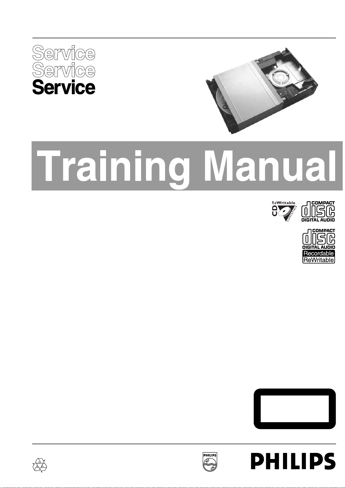
The following steps have to be done when replacing the CD mechanism:
1. Disconnect flexfoil from old CD drive
2. Put a paperclip over contacts of flexfoil to short-circuit the contacts (fig.1)
3. Remove old CD drive
4. Remove paperclip from flexfoil
5. Connect flexfoil to new CD drive
6. Remove ESD-protection (solder joint) from laserunit (see below)
7. Position new CD drive in its studs
CHARGED CAPACITORS ON THE SERVO BOARD MAY DAMAGE THE CD DRIVE ELECTRONICS WHEN
CONNECTING A NEW CDM MECHANISM. THAT´S WHY, BESIDES THE SAFETY MEASURES LIKE
• SWITCH OFF POWER SUPPLY
• ESD PROTECTION
ADDITIONAL ACTIONS MUST BE TAKEN BY THE REPAIR TECHNICIAN.
WARNING
fig.1
Attention: The laser diode of this CD drive is protected against ESD by a solder joint which shortcircuits the
laserdiode to ground.
For proper functionality of the CD drive this solder joint must be removed after connection the drive to
the set.
Page 3
3
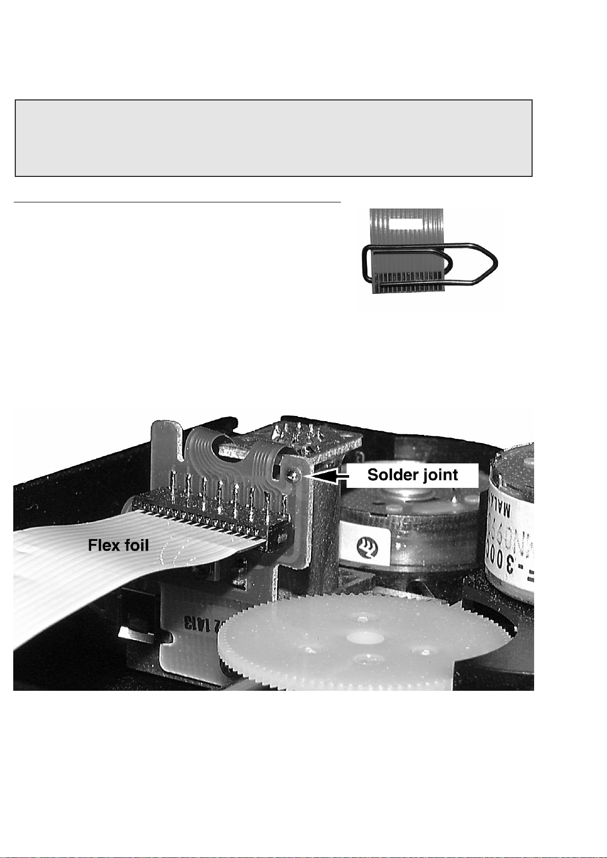
WIRING
Module
WIRING
CD Drive
Page 4
Brief description
On the next pages various actions of the 3 Disc Tray Changer are described with simplified drawings.
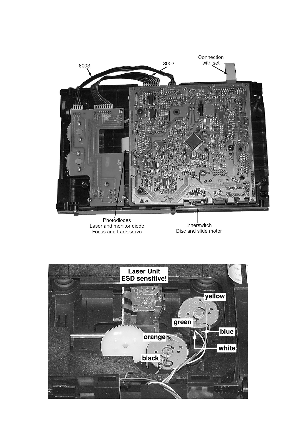
1. Initial state. After Power on the changer is in this position.
The drawer closed
Carriage #1 is in Play position
Carriage #2 and #3 are in home position
The Changer looks like
2. Tray open.
The Drawer is moved out
Carriage #2 and #3 remain in home position
The Changer looks like
2
3
1
Carriage
Drawer
Clamper
2
3
1
Carriage
Drawer
Clamper
4
Page 5

5
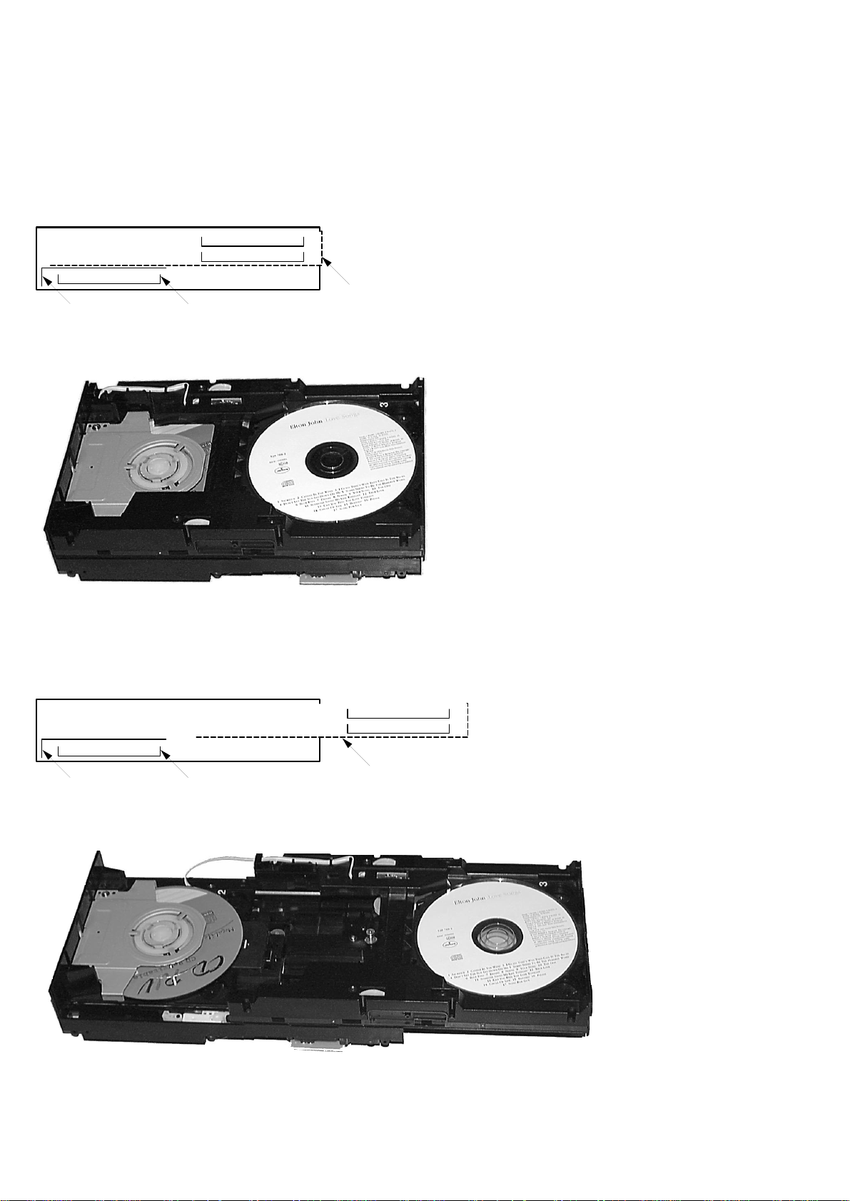
3. Carriage extra.
This position is necessary to get access to the lower carriage. It is also used during disc change.
The changer looks like
The various states are recognized by seven switches.
For functions see truth table on next page.
2
3
1
Carriage
Carriage extra position
Drawer
Clamper
SW8
SW7
SW6
SW2&3
SW4&5
Location of switches
Page 6

Truth Table
Slider reverse recognition
Slider forward recognition
Drawer closed recognition
No carriage under clamper
Carriage #1 under clamper
Carriage #2 under clamper
Carriage #3 under clamper
Carriage home recognition
Carriage extra recognition
1
0
0
0
0
0
0
0
0
0
1
0
0
0
0
0
0
0
0
0
1
0
0
0
0
0
0
0
0
0
0
0
1
1
0
0
0
0
0
0
1
0
1
0
0
0
0
0
0
0
0
0
1
0
0
0
0
0
0
0
0
0
1
X
X
X
X
X
X
X
X
X
SW
8
Function
SW7SW6SW5SW4SW3SW2-
Q0 Q1 Q2 Q3 Q4 Q5 Q6 Q7
Register output / Switch
6
Page 7

Timing Diagrams
1. Open #3
2. Close #3
Time 200ms/div
ActionRecognition
CCW
STOP
CW
CCW
STOP
CW
SW 2
SW 3
SW 4
SW 5
SW 6
SW 7
SW 8
Switches
Carriage
motor
Drawer
motor
initial final
2
3
1
2
3
1
2
3
1
2
3
1
2
3
1
press close
ACTION
Carriage #2
to home position
Drawer closes prepare for
next action
duty cycle 50%
(brake)
Time 200ms/div
ActionRecognition
CCW
STOP
CW
CCW
STOP
CW
SW 2
SW 3
SW 4
SW 5
SW 6
SW 7
SW 8
Switches
Carriage
motor
Drawer
motor
initial final
2
3
1
2
3
1
2
3
1
2
3
1
press open #3
ACTION
Carriage #2
to extra position
Drawer opens prepare for
next action
duty cycle 50%
(brake)
7
Page 8

3. Select #2
4. Select #1
Time 200ms/div
ActionRecognition
CCW
STOP
CW
CCW
STOP
CW
SW 2
SW 3
SW 4
SW 5
SW 6
SW 7
SW 8
Switches
Carriage
motor
Drawer
motor
initial
3
1
2
3
1
2
final
2
3
1
select #1
ACTION
clamper
up
clamper
down
carriage#1
to play position
2
3
1
3
2
1
3
1
2
1
2
3
Time 200ms/div
ActionRecognition
CCW
STOP
CW
CCW
STOP
CW
SW 2
SW 3
SW 4
SW 5
SW 6
SW 7
SW 8
Switches
Carriage
motor
Drawer
motor
initial
2
3
1
2
3
1
final
3
1
2
select #2
ACTION
clamper
up
clamper
down
carriage#2
to play position
2
3
1
32
1
3
1
2
1
2
3
8
Page 9

9
Load all discs
1. Power on. Initial state.
2. Press open #2.
Tray moves out.
Load carriage #2.
3. Press open #3.
Carriage #2 moves in extra position.
4. Load carriage #3.
5. Press open #1.
Tray closes.
6. Carriage #2 moves in home position.
7. Clamper moves to upper position.
Carriage #1 moves to height of carriage #3.
8. Carriage #1 moves to height of carriage #2.
9. Carriage #3 moves below carriage #1.
10. Carriage #2 moves down.
11. Carriage #1 moves in home position.
12. Carriage #3 and clamper move down (in play
position).
13. Tray moves out.
Load carriage #1.
14. Press close.
Tray closes.
insert disc
insert disc
insert disc
2
3
1
2
3
1
2
3
1
2
3
1
2
3
1
2
3
1
2
3
1
2
3
1
2
3
1
2
3
1
2
3
1
2
3
1
2
3
1
2
3
1
2
3
1
2
3
1
2
3
1
2
3
1
2
3
1
2
3
1
2
3
1
2
3
1
2
3
1
2
3
1
2
3
1
2
3
1
2
3
1
Page 10

10
2
3
1
2
3
1
2
3
1
2
3
1
2
3
1
2
3
1
212
3
1
212
3
1
2
3
1
3
1
2
2
3
1
2
3
1
2
3
1
2
3
1
2
3
1
2
3
1
2
3
1
2
3
1
2
3
1
2
3
1
2
3
1
1
2
3
Change
‘backwards’
E.g. select #3 while playing #1.
Change
‘forwards’
E.g. select #2 while playing #1.
See also timing diagrams (page 8).
Additional hints:
Gears pos. 4 and pos. 5 are responsible for forward/backward movement of the carriages.
Star Gears pos. ( are responsible for up/down movement of the carriages.
Mis-aligned gears (pos. 4 & 5) result in jamming carriages.
Wrong inserted carriages (e.g. #2 mixed up with #3) causes endless forward/backward changing of the loader module.
Page 11

Replacing the CD Drive
1. Dismantle top and side cover of set.
2. Loosen 4x screw (see picture 1).
Remove metal cover of changer.
3. Connect mains and switch on the set.
4. Press Open/Close CD button → Tray moves outside.
5. Disconnect mains.
6. Loosen 2x screw (see picture 2).
Remove bracket with clamper.
7. Remove carriage above CD-drive.
8. Loosen 4x screw (see picture 3).
Remove CD-drive.
9. Disconnect flex foil and short-circuit it
(see page 2).
10. Desolder wires.
11. Remove dampers pos. 57 and 58.
12. Insert dampers into new CD-drive.
13. Solder wires to new CD-drive (see page 3).
14. Connect flexfoil.
15. Remove solder joint on new CD-drive
(see page 3).
16. Position the new CD drive in its studs.
17. Fix the drive - 4x screw (see picture 3).
18. Insert carriage.
19. Mount bracket with clamper - 2x screw (see picture 2).
20. Mount metal cover of the loader unit - 4x screw
(see picture 1).
21. Connect mains → Press Open/Close CD button →
Tray closed.
11
Repair Tips
picture 1
picture 2 picture 3
Page 12

12
Jammed carriage, blocked tray
If the tray can´t be opened via open close dismantle the top and side cover of the set and remove the
metal cover of the loader unit as shown in picture 1.
If the carriage is in a position as shown in picture 4, the complete loader unit is locked.
In this state clamper A is in upper position and carriage B is jammed under the clamper.
Problem : The tray cannot open as long as the clamper is in upper position and the clamper cannot
move down because of the jammed carriage.
picture 4
The problem can only be fixed as follows
1. Loosen 2x screw (see picture 5).
Remove bracket with clamper.
2. Shift lever (pin) to the left as shown in picture 6. This action
releases the tray.
picture 5
picture 6
Page 13

13
picture 7
3. Shift lever (block) backwards as
shown in picture 7 → Tray moves
approx. 1cm outside.
4. Pull out the tray manually.
5. Remove carriage above the CD-drive.
WARNING: Don´t apply mechanical
force to the tray. Bend carriage - as
shown in picture 8 - to release
guidings.
Jammed carriage, blocked tray (
c
ontinued)
picture 8
6. Turn pulley as shown in picture 9 to
move next carriage over CD-drive.
7. If necessary repeat step 5 and 6 until all
carriages are removed.
picture 9
Page 14

14
Reassembling the tray
1. Insert carriage #1 above CD-drive.
Attention: The 3 cartridges are different (see picture 10).
2. Mount clamper (2x screw - see picture 5).
3. Connect mains. Set initializes → Clamper moves down.
4. Select CD 2 → Clamper moves up → Carriage #2 (not yet
inserted) will be moved above CD-drive → Carriage #1 moves
back → Clamper moves down.
5. While clamper moves down disconnect mains.
6. Open tray - using lever (block) as shown in picture 7.
Lift clamper - using lever (pin) as shown in picture 11.
7. Insert carriage #2 above CD-drive.
8. Lower clamper, close tray, connect mains.
Set initializes → carriage #1 moves above CD-drive →
Clamper moves down.
9. Select CD 3. → Clamper moves up → carriage #3 (not yet
inserted) will be moved above CD-drive → carriage #1 moves
back → Clamper moves down.
10. While clamper moves down disconnect mains.
11. Open tray - using lever (block) as shown in picture 7.
Lift clamper - using lever (pin) as shown in picture 11.
12. Insert carriage #3 above CD-drive.
13. Lower clamper, close tray, connect mains.
Set initializes → Carriage #1 moves above CD-drive → Loader
unit reassembled successfully.
picture 10
picture 11
Move lever to
unlock clamper
Page 15

15
Replacing the Gears (pos. 3 & 4)
1. Disassemble complete Loader unit.
2. Shift lever (block) backwards as shown in picture 7 →
Tray moves approx. 1cm outside. Pull out the tray
manually.
3. Demount right side of tray (see picture 12).
4. Close tray (simply push inside).
5. Demount left side of tray (see picture 13).
Lift right side as high as possible.
Attention:The two gearwheels shown in detail A resp.
detail B come loose easily!
picture 12
picture 13
picture 14
Detail A
Detail B
Page 16

16
picture 15
picture 16
Replacing the Gears (continued)
6. Turn gearwheel A as shown in
picture 15 → carriage moves
right.
7. Lift carriage as shown in
picture 16 and remove it.
8. Turn gearwheel A in the other
direction → remaining carriage
moves right.
9. Lift carriage as shown in
picture 16 and remove it.
10. Turn round tray and align gear as
shown in picture 17, detail C.
11. Fix the gear with a pin
(e.g. a paperclip d=1mm) see
detail B.
12. Loosen 4x screw as shown in
picture 17, detail D.
Detail C
picture 17
Detail D
Page 17

17
Replacing the Gears (continued)
13. Replace gear pos.3 and/or 4. Make sure that the new gear
is aligned as shown in picture 17, detail C as well. To
avoid damage of the switches when inserting the gear, use
a strip of paper as shown in picture 18.
14. Fix gear with 4x screw (see picture17,D).
15. Check if gear is aligned as shown in picture 17 detail C.
Inserting the Carriages
16. Turning gear A as shown in picture 19 will move the upper
and lower wheel of gear B alternately.
Turn gear A until the lower wheel stops moving and upper
one starts moving.
17. Insert right side of carriage #3 (= side with the toothrack)
as shown in picture 20.
picture 18
picture 19
Detail B
Detail A
picture 20
Page 18

18
Inserting the Carriages (continued)
18. Insert other side of carriage as shown in picture 21.
19. Turning gear A as shown in picture 19 will move
carriage inside. After reaching the endposition the
upper wheel (picture19 B) starts turning.
20. Insert carriage #2 as shown in picture 20 and 21.
21. Lift carriage #3 while turning gear A (see picture 22).
22. Lift clamper and insert carriage #1 above CD-drive.
23. Shift lever as shown in picture 23.
picture 21
picture 22
picture 23
Assembling the Tray
24. Lift back side of tray as high as
possible.
Assemble tray starting at position 1
as shown in picture 24.
picture 24
Page 19

19
Assembling the Tray (continued)
25. Move tray outside (simply pull the tray).
26. Align toothed wheel A as shown in picture 25.
27. Snap in other side of tray as shown in picture 26.
28. Move tray inside (simply push).
29. Done.
picture 25
Detail
picture 26
Page 20

20
3Disc T ray Changer
Exploded view
Exploded view 3DTC 2000 08 22
19
19
23
4
11
33
A
121
34
41
50
72
77
30
121
43
1
37
85
53
47
51
52
35
32
121
115
115
120
57
57
58
59
58
18
54
36
25
29
39
40
113
49
71
48
123
115
31
28
26
24
27
60
113
19
19
3
12
62
56
118
118
118
118
119
119
119
75
72
68
63
38
2
127
3x
A
MECHANICAL PARTS
–––––––––––––––––––––––––––––––––––––––––––––––––––––
3 9965 000 06538 ASSY HOLDER LEFT
4 9965 000 06539 ASSY HOLDER RIGHT
12 9965 000 06540 ASSY CARRIAGE 1 (TOP)
19 9965 000 06541 ASSY GEAR STAR
48 9965 000 06542 ASSY MOTOR CARRIAGE
49 9965 000 06543 ASSY MOTOR DRAWER
53 9965 000 06544 BELT DRAWER
54 9965 000 06545 BELT CARRIAGE
57 9965 000 06546 DAMPER RUBBER REAR
58 9965 000 06547 DAMPER RUBBER FRONT
59 9305 022 30103 CD DRIVE VAM2201/03 (1x SPEED)
59 9305 022 30203 CD DRIVE VAM2202/03 (2x SPEED)
59 8203 303 85780 CD DRIVE VAM2204/03 (4x SPEED)
62 9965 000 06548 ASSY CARRIAGE 2 (MIDDLE)
63 9965 000 06549 ASSY CARRIAGE 3 (BOTTOM)
71 4822 277 11652 SWITCH (SW6-SW8)
72 9965 000 06550 SWITCH (SW2-SW5)
3103 309 05250 3DTC MECH. CMCJ-01-13 (1xSPEED)
3103 309 05260 3DTC MECH. CMCJ-01-14(2xSPEED)
3103 309 05270 3DTC MECH. CMCJ-01-15(4xSPEED)
Complete Mechanic - CD Drive already included
 Loading...