

Page 1

Nortel Secure Router 8012
Hardware Description
Release:
Document Revision:
www.nortel.com
5.3
01.0
3
NN46240-303 324566-A
Page 2

Nortel Secure Router 8012
Release: 5.3
Publication: NN46240-303
Document Revision: 01.03
Document status: Standard
Document release date: 6 April 2009
Copyright © 2009 Nortel Networks
All Rights Reserved.
Printed in Canada, India, and the United States of America
LEGAL NOTICE
While the information in this document is believed to be accurate and reliable, except as otherwise expressly
agreed to in writing NORTEL PROVIDES THIS DOCUMENT "AS IS" WITHOUT WARRANTY OR CONDITION OF
ANY KIND, EITHER EXPRESS OR IMPLIED. The information and/or products described in this document are
subject to change without notice.
Nortel, the Nortel logo, and the Globemark are trademarks of Nortel Networks.
All other trademarks are the property of their respective owners.
ATTENTION
For information about the safety precautions, read "Safety messages" in this guide.
For information about the software license, read "Software license" in this guide.
Page 3

Nortel Secure Router 8012
Hardware Description
Contents
About this document.......................................................................................................................1
1 Overview......................................................................................................................................1-1
1.1 Introduction.................................................................................................................................................1-2
1.2 Structure......................................................................................................................................................1-2
1.3 System configuration and physical specifications.......................................................................................1-5
1.3.1 System configuration.........................................................................................................................1-5
1.3.2 Physical specifications ......................................................................................................................1-6
2 Power supply ..............................................................................................................................2-1
2.1 Appearance and front panel.........................................................................................................................2-2
2.1.1 Appearance........................................................................................................................................2-2
2.1.2 Front panel ........................................................................................................................................2-2
2.2 Functions.....................................................................................................................................................2-4
2.3 T ec hnical specifications...............................................................................................................................2-5
3 Heat dissipation system............................................................................................................3-1
3.1 Appearance and front panel.........................................................................................................................3-2
3.1.1 Appearance........................................................................................................................................3-2
3.1.2 Front panel ........................................................................................................................................3-2
3.2 Functions.....................................................................................................................................................3-3
3.3 T ec hnical specifications...............................................................................................................................3-4
4 Boards...........................................................................................................................................4-1
4.1 Introduction.................................................................................................................................................4-3
4.1.1 Board classification and slot arrangement.........................................................................................4-3
4.1.2 Logical relationship among boards...................................................................................................4-6
4.1.3 Board appearance..............................................................................................................................4-7
4.1.4 Interface types and distribution on the boards...................................................................................4-9
4.2 RPUs..........................................................................................................................................................4-11
4.2.1 Functions.........................................................................................................................................4-11
4.2.2 Front panel ......................................................................................................................................4-12
4.2.3 Interfaces.........................................................................................................................................4-14
4.2.4 Interface attributes...........................................................................................................................4-14
4.2.5 Technical specifications...................................................................................................................4-16
Issue 5.3 (6 April 2009)
Nortel Networks Inc.
i
Page 4

Nortel Secure Router 8012
4.3 NPUs.........................................................................................................................................................4-16
4.3.1 Functions.........................................................................................................................................4-16
4.3.2 Front panel ......................................................................................................................................4-17
4.3.3 Technical specifications...................................................................................................................4-17
4.4 10/100Base-TX electrical interface module..............................................................................................4-18
4.4.1 Functions.........................................................................................................................................4-18
4.4.2 Front panel ......................................................................................................................................4-18
4.4.3 Interface attributes...........................................................................................................................4-19
4.5 100Base-FX Ethernet optical interface module.........................................................................................4-19
4.5.1 Functions.........................................................................................................................................4-19
4.5.2 Front panel ......................................................................................................................................4-20
4.5.3 Interface attributes...........................................................................................................................4-20
4.6 1000Base-X Ethernet optical interface module.........................................................................................4-21
4.6.1 Functions.........................................................................................................................................4-21
4.6.2 Front panel ......................................................................................................................................4-21
4.6.3 Interface attributes...........................................................................................................................4-22
4.7 Channelized and unchannelized E1/T1 interface module..........................................................................4-24
4.7.1 Functions.........................................................................................................................................4-24
4.7.2 Front panel ......................................................................................................................................4-24
4.7.3 Interface attributes...........................................................................................................................4-27
4.8 Channelized E3 interface modules............................................................................................................4-28
4.8.1 Functions.........................................................................................................................................4-28
4.8.2 Front panel ......................................................................................................................................4-28
4.8.3 Interface attributes...........................................................................................................................4-28
4.9 Synchronous serial port module................................................................................................................4-29
4.9.1 Functions.........................................................................................................................................4-29
4.9.2 Front panel ......................................................................................................................................4-31
4.9.3 Interface attributes...........................................................................................................................4-31
4.10 Channelized and unchannelized POS optical interface modules.............................................................4-36
4.10.1 Functions.......................................................................................................................................4-36
4.10.2 Front panel ....................................................................................................................................4-37
4.10.3 Interface attributes.........................................................................................................................4-38
4.11 HSSI interface module.............................................................................................................................4-38
4.11.1 Functions.......................................................................................................................................4-38
4.11.2 Front panel.....................................................................................................................................4-39
4.11.3 Interface attributes.........................................................................................................................4-39
4.12 IPSec encryption HIC module.................................................................................................................4-40
4.12.1 Function.........................................................................................................................................4-40
4.12.2 Front panel ....................................................................................................................................4-40
4.12.3 Module attributes...........................................................................................................................4-41
Hardware Description
5 Cables ...........................................................................................................................................5-1
ii
Nortel Networks Inc.
Issue 5.3 (6 April 2009)
Page 5

Nortel Secure Router 8012
Hardware Description
5.1 DC power cable...........................................................................................................................................5-2
5.1.1 Introduction.......................................................................................................................................5-2
5.1.2 Structure............................................................................................................................................5-2
5.2 AC powe r cable...........................................................................................................................................5-2
5.2.1 Introduction.......................................................................................................................................5-2
5.2.2 Structure............................................................................................................................................5-3
5.3 Console port cable.......................................................................................................................................5-3
5.3.1 Introduction.......................................................................................................................................5-3
5.3.2 Structure............................................................................................................................................5-3
5.4 Auxiliary port communication cable ...........................................................................................................5-4
5.4.1 Introduction.......................................................................................................................................5-4
5.4.2 Structure............................................................................................................................................5-4
5.5 Ethernet cable..............................................................................................................................................5-5
5.5.1 Introduction.......................................................................................................................................5-5
5.5.2 Structure............................................................................................................................................5-5
5.6 Optical fiber.................................................................................................................................................5-6
5.6.1 Introduction.......................................................................................................................................5-6
5.6.2 Optical connector ..............................................................................................................................5-7
5.7 Channelized and unchannelized E1/T1 interface cable...............................................................................5-8
5.7.1 4E1/4CE1 interface cable..................................................................................................................5-8
5.7.2 8E1/8CE1 interface cable................................................................................................................5-13
5.7.3 16CE1 interface cable .....................................................................................................................5-18
5.7.4 4CT1/8CT1 interface cable.............................................................................................................5-25
5.7.5 16CT1 interface cable .....................................................................................................................5-25
5.8 Channelized E3 interface cable.................................................................................................................5-25
5.8.1 Introduction.....................................................................................................................................5-25
5.8.2 Structure..........................................................................................................................................5-25
5.9 Synchronous serial interface cable............................................................................................................5-26
5.9.1 Introduction.....................................................................................................................................5-26
5.9.2 Structure..........................................................................................................................................5-26
5.10 HSSI cable...............................................................................................................................................5-30
5.10.1 Introduction...................................................................................................................................5-30
5.10.2 Structure........................................................................................................................................5-30
A List of indicators...................................................................................................................... A-1
A.1 Board indicators.........................................................................................................................................A-1
A.1.1 RPU indicators ................................................................................................................................A-1
A.1.2 NPU indicators................................................................................................................................A-2
A.1.3 HIC/FIC indicators..........................................................................................................................A-2
A.2 Fan module indicators...............................................................................................................................A-3
A.3 Power module indicators...........................................................................................................................A-3
B List of boards.............................................................................................................................B-1
Issue 5.3 (6 April 2009)
Nortel Networks Inc.
iii
Page 6

Nortel Secure Router 8012
B.1 Boards ........................................................................................................................................................ B-1
B.2 RPU ........................................................................................................................................................... B-2
B.3 10/100Base-TX FE electrical interface module......................................................................................... B-4
B.4 100Base-FX Ethernet optical interface module.........................................................................................B-4
B.5 1000Base-X Ethernet optical interface module.........................................................................................B-5
B.6 Channelized and unchannelized E1/T1 interface module....................................................................... ... B-7
B.7 Channelized E3 interface modules.............................................................................................................B-8
B.8 Synchronous serial port module.................................................................................................................B-8
B.9 A TM 155M optical interface module.........................................................................................................B-9
B.10 ATM over E3 interface module..............................................................................................................B-10
B.11 Channelized and unchannelized POS optical interface module............................................................. B-11
B.12 HSSI interface module........................................................................................................................... B-12
B.13 IPSec encryption HIC............................................................................................................................B-12
Hardware Description
C Acronyms and abbreviations .................................................................................................C-1
Index ................................................................................................................................................ i-1
iv
Nortel Networks Inc.
Issue 5.3 (6 April 2009)
Page 7

Nortel Secure Router 8012
Hardware Description
Figures
Figure 1-1 Front panel of the Secure Router 8012 ...........................................................................................1-3
Figure 1-2 Rear panel of the Secure Router 8012.............................................................................................1-4
Figure 2-1 Appearance of the AC power supply module..................................................................................2-2
Figure 2-2 Appearance of the DC power supply module..................................................................................2-2
Figure 2-3 Front panel of the AC power module..............................................................................................2-2
Figure 2-4 Front panel of the DC power module..............................................................................................2-3
Figure 3-1 Appearance of the fan in the Secure Router 8012...........................................................................3-2
Figure 3-2 Appearance of the fan front panel of the Secure Router 8012........................................................3-3
Figure 3-3 Air flow inside the Secure Router 8012..........................................................................................3-4
Figure 4-1 Arrangement of the Secure Router 8012 slots on the backplane (front view).................................4-4
Figure 4-2 Arrangement of the Secure Router 8012 slots on the backplane (rear view)..................................4-4
Figure 4-3 Logical relationship among the boards of a Secure Router 8012....................................................4-7
Figure 4-4 Components on an RPU ..................................................................................................................4-8
Figure 4-5 Components on an NPU board........................................................................................................4-8
Figure 4-6 Components on an HIC/FIC ...........................................................................................................4-9
Figure 4-7 Appearance of the RPU front panel ..............................................................................................4-12
Figure 4-8 Appearance of the NPU front panel..............................................................................................4-17
Figure 5-1 DC power cable...............................................................................................................................5-2
Figure 5-2 Console port cable...........................................................................................................................5-3
Figure 5-3 Schematic diagram of straight-through cable..................................................................................5-5
Figure 5-4 Schematic diagram of crossover cable............................................................................................5-5
Figure 5-5 SC/PC optical connector.................................................................................................................5-8
Figure 5-6 LC/PC optical connector.................................................................................................................5-8
Figure 5-7 The 75-ohm 4E1/4CE1 coaxial cable .............................................................................................5-9
Figure 5-8 The 120-ohm 4E1/4CE1 shielded twisted-pair cable..................................................................5-10
Figure 5-9 75-ohm 8E1/8CE1 coaxial cable...................................................................................................5-13
Issue 5.3 (6 April 2009)
Nortel Networks Inc.
v
Page 8

Nortel Secure Router 8012
Hardware Description
Figure 5-10 120-ohm 8E1/8CE1 shielded twisted-pair cable.........................................................................5-14
Figure 5-11 75-ohm 16CE1 coaxial cable......................................................................................................5-19
Figure 5-12 120-ohm 16CE1 shielded twisted-pair cable..............................................................................5-19
Figure 5-13 E3 interface cable........................................................................................................................5-26
Figure 5-14 V.24 DTE cable...........................................................................................................................5-26
Figure 5-15 V.24 DCE cable...........................................................................................................................5-27
Figure 5-16 V.35 DTE cable...........................................................................................................................5-27
Figure 5-17 V.35 DCE cable...........................................................................................................................5-27
Figure 5-18 E3 cable outline ..........................................................................................................................5-30
Figure 5-19 DTE-to-DCE cable......................................................................................................................5-31
vi
Nortel Networks Inc.
Issue 5.3 (6 April 2009)
Page 9

Nortel Secure Router 8012
Hardware Description
Tables
Table 1-1 Secure Router 8012 components ......................................................................................................1-4
Table 1-2 System configuration data ................................................................................................................1-5
Table 1-3 Physical specifications......................................................................................................................1-6
Table 2-1 Relationship of the terminal block connection of the power input cable..........................................2-3
Table 2-2 Description of the indicators on the AC power supply module ........................................................2-3
Table 2-3 Description of the indicators on the DC power supply module........................................................2-4
Table 2-4 Technical specificationss of the power module.................................................................................2-5
Table 3-1 Description of the fan module indicators..........................................................................................3-3
Table 3-2 Technical specifications of the fan module.......................................................................................3-4
Table 4-1 Working modes of the Secure Router 8012 ......................................................................................4-5
Table 4-2 Allowed HICs in different modes of the Secure Router 8012...........................................................4-6
Table 4-3 Board dimensions .............................................................................................................................4-9
Table 4-4 Interface distribution on the boards ..................................................................................................4-9
Table 4-5 Description of the components on the front panel of an RPU ........................................................4-12
Table 4-6 The interfaces on the RPU and their usage.....................................................................................4-14
Table 4-7 Console interface attributes ............................................................................................................4-14
Table 4-8 AUX interface attributes .................................................................................................................4-15
Table 4-9 Attributes of the 10/100/1000M Ethernet interface........................................................................4-15
Table 4-10 Attributes of the 100/1000M Ethernet interface............................................................................4-15
Table 4-11 T echnical specifications of the RPU .............................................................................................4-16
Table 4-12 Description of the NPU indicators................................................................................................4-17
Table 4-13 Description of the NPU technical specifications ..........................................................................4-17
Table 4-14 Description of the 10/100Base-TX Ethernet electrical interface module .....................................4-18
Table 4-15 Description of indicators of the 10/100Base-TX Ethernet electrical interface module ................4-19
Table 4-16 Attributes of the 10/100Base-TX Ethernet electrical interface module........................................4-19
Table 4-17 Description of the 100Base-FX Ethernet optical interface module ..............................................4-20
Issue 5.3 (6 April 2009)
Nortel Networks Inc.
vii
Page 10

Nortel Secure Router 8012
Hardware Description
Table 4-18 Description of the indicators of the 100Base-FX Ethernet optical interface module....................4-20
Table 4-19 Attributes of the 100Base-FX Ethernet optical interface..............................................................4-20
Table 4-20 Attributes of the 100Base-FX Ethernet interface SFP optical module..........................................4-21
Table 4-21 Description of the 1000Base-X Ethernet optical interface module...............................................4-22
Table 4-22 Description of the indicators of the 1000Base-X Ethernet optical interface module....................4-22
Table 4-23 Attributes of the 1000Base-X Ethernet optical interface module..................................................4-22
Table 4-24 Attributes of the 1000Base-X Ethernet interface SFP optical module..........................................4-23
Table 4-25 Attributes of SFP electrical interface module of 1000Base-X Ethernet interface.........................4-23
Table 4-26 Description of the channelized and unchannelized E1 interface modules....................................4-25
Table 4-27 Description of the channelized T1 interface modules ...................................................................4-26
Table 4-28 Description of the indicators of channelized and unchannelized E1/T1 interface modules..........4-26
Table 4-29 Attributes of the channelized and unchannelized E1/T1 interface modules..................................4-27
Table 4-30 Description of the channelized E3 interface module ....................................................................4-28
Table 4-31 Description of the indicators of the channelized E3 interface module..........................................4-28
Table 4-32 Attributes of the channelized E3 interface module.......................................................................4-29
Table 4-33 Typical DTE and DCE devices.....................................................................................................4-30
Table 4-34 V.24/V.35 cable rate and transmission distance ............................................................................4-30
Table 4-35 Description of the synchronous serial port module.......................................................................4-31
Table 4-36 Description of the indicators of a synchronous serial port module...............................................4-31
Table 4-37 Attributes of the 4SAE interface module......................................................................................4-31
Table 4-38 Description of the ATM 155M optical interface module ..............................................................4-32
Table 4-39 Description of the indicators on the ATM 155M optical interface module...................................4-33
Table 4-40 Attributes of the ATM 155M optical interface module.................................................................4-33
Table 4-41 Attributes of the FIC low-speed ATM 155M SFP optical module................................................4-34
Table 4-42 Description of the ATM over E3 interface module.......................................................................4-35
Table 4-43 Description of the indicators of the ATM over E3 interface module ............................................4-35
Table 4-44 Attributes of A TM over E3 interface module................................................................................4-35
Table 4-45 Description of channelized and unchannelized POS optical interface modules ...........................4-37
viii
Table 4-46 Description of the indicators on the front panel of POS optical interface modules......................4-38
Table 4-47 Attributes of channelized and unchannelized POS optical interface modules ..............................4-38
Table 4-48 Description of the HSSI front panel..............................................................................................4-39
Table 4-49 Description of the indicators of the HSSI front panel...................................................................4-39
Table 4-50 Attributes of the HSSI interface module.......................................................................................4-40
Nortel Networks Inc.
Issue 5.3 (6 April 2009)
Page 11

Nortel Secure Router 8012
Hardware Description
Table 4-51 Front panel of an IPSec encryption HIC module..........................................................................4-40
Table 4-52 Description of the indicators of an IPSec encryption HIC module...............................................4-40
Table 4-53 Attributes of the IPSec encryption HIC module ...........................................................................4-41
Table 5-1 Pin assignment of console cables......................................................................................................5-3
Table 5-2 Pin assignment of AUX cables .........................................................................................................5-4
Table 5-3 Pin assignment of straight-through cable..........................................................................................5-6
Table 5-4 Pin assignment of crossover cable....................................................................................................5-6
Table 5-5 Relationship between the interface type and corresponding optical fiber.........................................5-7
Table 5-6 Pin assignment of 4E1/4CE1 coaxial cable ....................................................................................5-10
Table 5-7 Pin assignment of 4E1/4CE1 shielded twisted-pair cable...............................................................5-12
Table 5-8 Pin assignment of 8E1/8CE1 coaxial cable ....................................................................................5-14
Table 5-9 Pin assignment of 8E1/8CE1/8CT1 shielded twisted-pair cable ....................................................5-16
Table 5-10 Pin assignment of the 16CE1 coaxial cable..................................................................................5-20
Table 5-11 Pin assignment of the 16CE1 shielded twisted-pair cable.............................................................5-22
Table 5-12 Pin assignment of the V.24 DTE cable .........................................................................................5-27
Table 5-13 Pin assignment of the V.24 DCE cable .........................................................................................5-28
Table 5-14 Pin assignment of the V.35 DTE cable..........................................................................................5-29
Table 5-15 Pin assignment of the V.35 DCE cable .........................................................................................5-29
Table 5-16 Pin assignment of the DTE-to-DCE cable (HSSI interface cable)................................................5-31
Table 5-17 Pin assignment of the DTE-to-DTE cable (null modem cable)....................................................5-33
Table A-1 Discription of the RPU front panel components.............................................................................A-1
Table A-2 Description of NPU indicators........................................................................................................A-2
Table A-3 HIC/FIC indicators..........................................................................................................................A-3
Table A-4 Indicators of the fan module ...........................................................................................................A-3
Table A-5 Indicators of the power module.......................................................................................................A-3
Table A-6 Indicators of the power module on the RPU front panel.................................................................A-4
Table B-1 Boards supported by the Secure Router 8012 .................................................................................B-1
Table B-2 Console interface attributes.............................................................................................................B-2
Table B-3 AUX interface attributes .................................................................................................................B-3
Table B-4 10/100/1000M Ethernet interface attributes....................................................................................B-3
Table B-5 Attributes of the 100/1000M Ethernet interface.............................................................................. B-4
Table B-6 Attributes of 10/100Base-TX FE electrical interfaces.....................................................................B-4
Table B-7 Attributes of the 100Base-FX Ethernet optical interface ................................................................ B-5
Issue 5.3 (6 April 2009)
Nortel Networks Inc.
ix
Page 12

Nortel Secure Router 8012
Table B-8 Attributes of the 100M-FX Ethernet interface SFP optical module................................................ B-5
Table B-9 Attributes of the 1000Base-X Ethernet interface module................................................................B-6
Table B-10 Attributes of the SFP optical module of the 1000Base-X Ethernet interface................................B-6
Table B-11 Att ributes of SFP module of 1000Base-X Ethernet electrical interface........................................B-7
Table B-12 Attributes of channelized and unchannelized E1/T1 interface......................................................B-7
Table B-13 Attributes of the channelized E3 interface module........................................................................B-8
Table B-14 Attributes of the 4SAE interface...................................................................................................B-8
Table B-15 Attributes of the ATM 155M optical interface ..............................................................................B-9
Table B-16 Attributes of the SFP optical module with the ATM 155M optical interface ..............................B-10
Table B-17 Attributes of the HIC high-speed ATM 155M SFP optical module............................................. B-10
Table B-18 Attributes of the ATM over E3 interface ..................................................................................... B-11
Table B-19 Attributes of the channelized and unchannelized POS optical interface..................................... B-11
Table B-20 Attributes of the SFP optical module of the channelized/unchannelized POS optical interface .B-12
Hardware Description
Table B-21 Attributes of the HSSI interface.................................................................................................. B-12
Table B-22 Attributes of the IPSec encryption HIC.......................................................................................B-13
x
Nortel Networks Inc.
Issue 5.3 (6 April 2009)
Page 13

Nortel Secure Router 8012
Hardware Description
Contents
About this document....................................................................................................................... 1
Issue 5.3 (6 April 2009)
Nortel Networks Inc.
i
Page 14

Page 15

Nortel Secure Router 8012
Hardware Description About this document
About this document
Purpose
This document introduces the Nortel Secure Router 8012 hardware, including the power
module, the heat dissipation system, the board, and the equipment cable.
Related versions
The following table lists the product versions related to this document.
Product Name Version
Nortel Secure Router 8012 V200R005
Intended audience
This document is intended for the following audience:
z
installers
z
network operators
z
network administrators
z
network maintenance engineers
Organization
This document consists of five chapters and is organized as follows.
Chapter Description
1 Overview This chapter describes the device structure, the system
2 Power supply This chapter describes the DC and AC power modules,
Issue 5.3 (6 April 2009)
configuration, and the physical specifications.
including the front panel, the functions, and the technical
specifications.
Nortel Networks Inc.
1
Page 16
About this document
Nortel Secure Router 8012
Hardware Description
Chapter Description
3 Heat dissipation system This chapter describes the heat dissipation system,
including the front panel, the functions and the technical
specifications.
4 Boards This chapter describes the classification of the boards, the
slot allocation, the interface types, and the allocation on the
boards. It also describes each board according to the
functions, the front panel, the interface description, the
attributes, and the technical specifications.
5 Cables This chapter describes the external cables, including the
structure and the technical specifications.
Appendixes A to C These sections contain a list of indicators, a list of boards,
and a list of acronyms and abbreviations. For daily
maintenance, you can use these sections to quickly find
information about the device.
Conventions
This section describes the symbol and text conventions used in this document.
Symbol conventions
Symbol Description
Indicates a hazard with a high level of risk that, if not avoided,
can result in death or serious injury.
Indicates a hazard with a medium or low level of risk that, if
not avoided, can result in minor or moderate injury.
Indicates a potentially hazardous situation that, if not avoided,
can cause equipment damage, data loss, and performance
degradation, or unexpected results.
Indicates a tip that may help you solve a problem or save time.
Provides additional information to emphasize or supplement
important points of the main text.
General conventions
Convention Description
Times New Roman Normal paragraphs are in Times New Roman font.
2
Nortel Networks Inc.
Issue 5.3 (6 April 2009)
Page 17

Nortel Secure Router 8012
Hardware Description About this document
Convention Description
Boldface
Italic Book titles are in italics.
Courier New
Command conventions
Convention Description
Boldface
Italic Command arguments are in italics.
[ ] Items (keywords or arguments) in square brackets [ ] are
{ x | y | ... } Alternative items are grouped in braces and separated by
[ x | y | ... ] Optional alternative items are grouped in square brackets
Names of files, directories, folders, and users are in
boldface. For example, log on as the user root.
Terminal display is in Courier New font.
The keywords of a command line are in boldface.
optional.
vertical bars. You select one item.
and separated by vertical bars. You select one item or no
item.
{ x | y | ... } * Alternative items are grouped in braces and separated by
&<1-n>
# A line starting with the number sign (#) contains comments.
GUI conventions
Convention Description
Boldface
> Multilevel menus are in boldface and separated by the
vertical bars. You can select a minimum of one item or a
maximum of all items.
The parameter before the ampersand sign (&) can be
repeated 1 to n times.
Buttons, menus, parameters, tabs, windows, and dialog box
titles are in boldface. For example, click OK.
right-angled bracket sign (>). For example, choose File >
Create > Folder.
Issue 5.3 (6 April 2009)
Nortel Networks Inc.
3
Page 18

About this document
Keyboard operation
Format Description
Nortel Secure Router 8012
Hardware Description
Key
Key 1+Key 2
Key 1, Key 2 Press the keys in sequence. For example, Alt, A means
Mouse operation
Action Description
Click Select and release the primary mouse button without
Double-click Press the primary mouse button twice quickly without
Drag Press and hold the primary mouse button and move the
Press the key. For example, press Enter and press Tab.
Press the keys concurrently. For example, Ctrl+Alt+A
means press the three keys concurrently.
press the two keys in sequence.
moving the pointer.
moving the pointer.
pointer to a new position.
Update history
Updates between document versions are cumulative. Therefore, the latest document version
contains all updates made to previous versions.
Updates in Issue 01 (2008-06-06)
This is the first commercial release of this document.
4
Nortel Networks Inc.
Issue 5.3 (6 April 2009)
Page 19

Nortel Secure Router 8012
Hardware Description
Contents
1 Overview......................................................................................................................................1-1
1.1 Introduction...................................................................................................................................................1-2
1.2 Structure........................................................................................................................................................1-2
1.3 System configuration and physical specifications.........................................................................................1-5
1.3.1 System configuration...........................................................................................................................1-5
1.3.2 Physical specifications.........................................................................................................................1-6
Issue 5.3 (6 April 2009) Nortel Networks Inc. i
Page 20

Page 21

Nortel Secure Router 8012
Hardware Description
Figures
Figure 1-1 Front panel of the Secure Router 8012.............................................................................................1-3
Figure 1-2 Rear panel of the Secure Router 8012..............................................................................................1-4
Issue 5.3 (6 April 2009) Nortel Networks Inc. iii
Page 22

Page 23

Nortel Secure Router 8012
Hardware Description
Tables
Table 1-1 Secure Router 8012 components........................................................................................................1-4
Table 1-2 System configuration data ..................................................................................................................1-5
Table 1-3 Physical specifications........................................................................................................................1-6
Issue 5.3 (6 April 2009) Nortel Networks Inc. v
Page 24

Page 25

Nortel Secure Router 8012
Hardware Description 1 Overview
1 Overview
About this chapter
The following table lists the contents of this chapter.
Title Description
1.1 Introduction This section describes the features of the Secure Router
8012.
1.2 Structure This section describes the appearance and hardware
structure of the Secure Router 8012.
1.3 System configuration and
physical specifications
This section describes the system configuration and
physical specifications of the Secure Router 8012.
Issue 5.3 (6 April 2009) Nortel Networks Inc. 1-1
Page 26

1 Overview
1.1 Introduction
The Nortel Secure Router 8012 is a high-end router developed by Nortel and designed for the
carrier aggregation layer and the enterprise backbone layer network. The Secure Router 8012
features include high performance, double Routing Process Units (RPUs), double Network
Process Units (NPUs), and hot backup.
The Secure Router 8012 has a modularized structure and provides the High-speed Interface
Card (HIC) and the Flexible Interface Card (FIC).
The hardware structure of the Secure Router 8012 provides the following attributes:
z
It supports hot swapping.
z
The backplane is in the middle. The boards are inserted in the backplane horizontally,
allowing easy configuration and maintenance.
z
The fan is located to the left of the router backplane. Multiple fans provide heat
dissipation.
The Secure Router 8012 also provides an effective monitoring system through the main
control module on the RPU. The RPU can manage, monitor, and maintain the board, the fan
module, and the power module.
Nortel Secure Router 8012
Hardware Description
The Secure Router 8012 adheres to electromagnet ic com patibili ty (EMC) and Underwriters
Laboratories Inc. (UL) standards. The entire system reaches the module-class shield level.
Every front panel is made of steel sheet to isolate the electromagnetic wave between boards.
1.2 Structure
The Secure Router 8012 provides the backplane in the middle and an integrated chassis with
the board inserted horizontally. The chassis is 6 U in height (1 U = 44.45 millimeters [mm])
and can be mounted in a 19-inch standard cabinet or on the workbench.
1-2 Nortel Networks Inc. Issue 5.3 (6 April 2009)
Page 27
Nortel Secure Router 8012
Hardware Description 1 Overview
Front panel
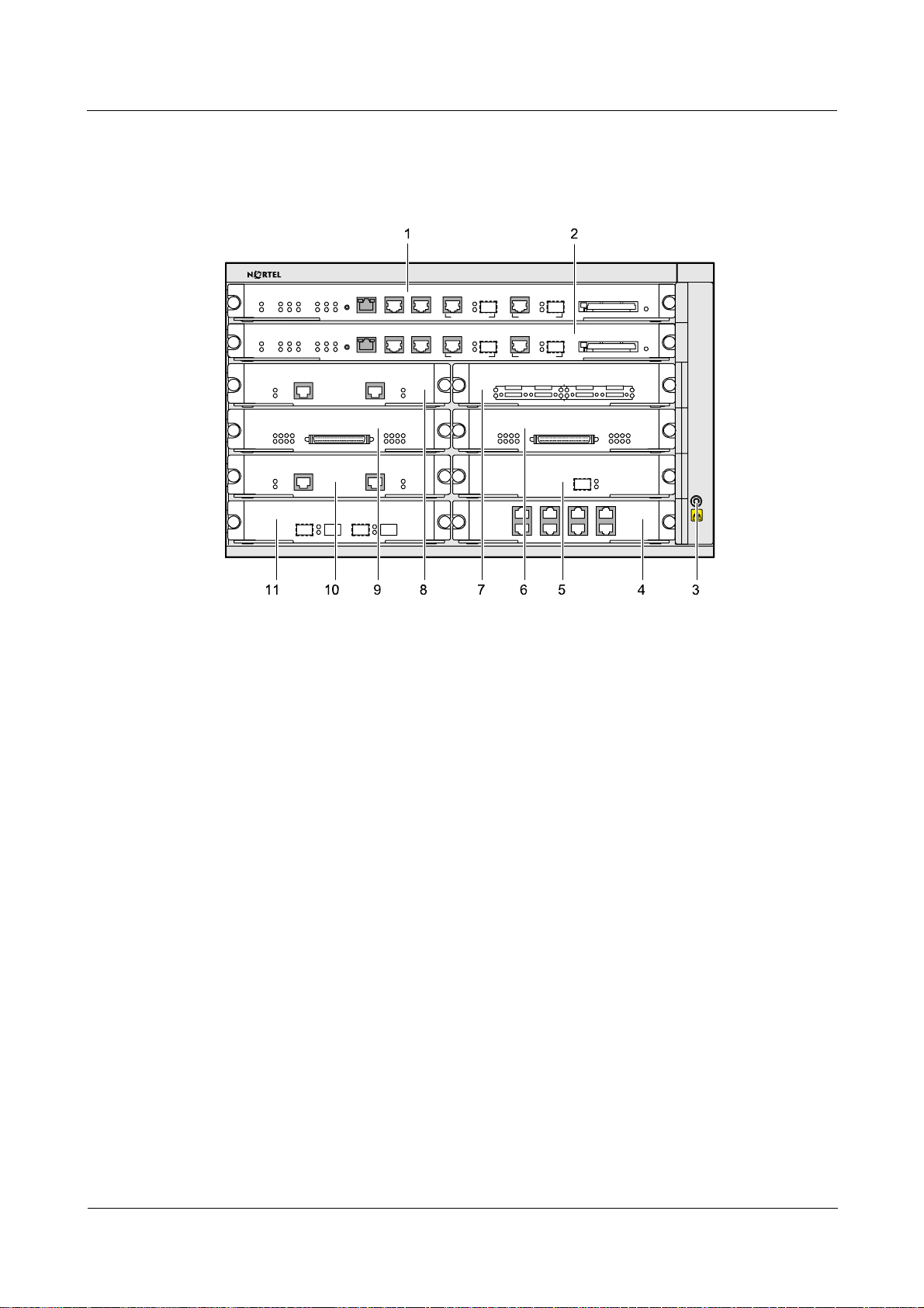
Figure 1-1 Front panel of the Secure Router 8012
Nortel Secure Router 8012
1. RPU 2-slot 10 2. RPU 1-slot 9 3.ESD-preventive wrist strap jack
4. FIC/HIC interface
module –slot 2
7. FIC interface
module –slot 8
10. FIC/HIC interface
module –slot 3
5. FIC/HIC interface module –slot 4 6. FIC interface module –slot 6
8. FIC/HIC interface module –slot 7 9. FIC/HIC interface module –slot 5
11. FIC/HIC interface module –slot 1
Issue 5.3 (6 April 2009) Nortel Networks Inc. 1-3
Page 28
1 Overview
Rear panel
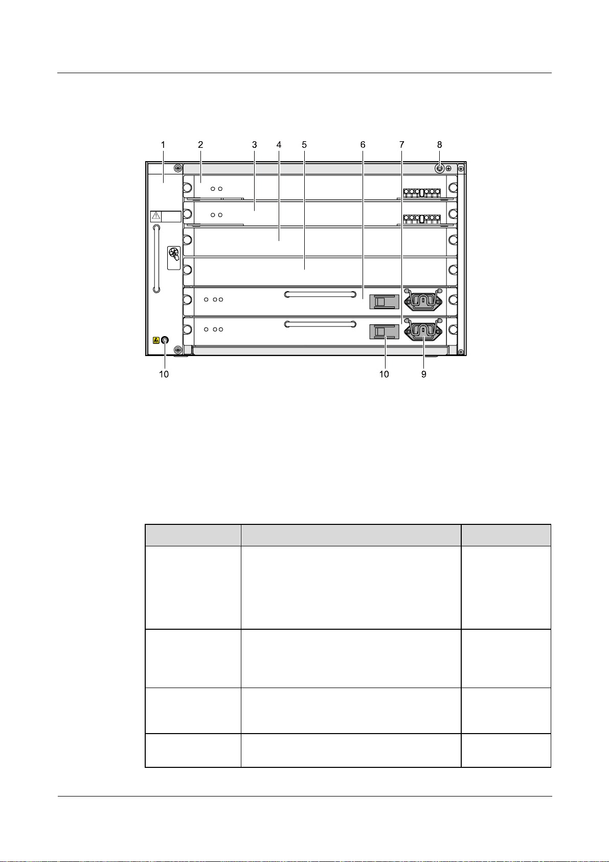
Figure 1-2 Rear panel of the Secure Router 8012
RUN
ALM
FAN
RUN
ALM
AC
R
AL
U
OK
M
N
A
RU
ALM
C
O
N
K
CAUTION
Don’t use this handle
to lift subrack
TOUCH THE
FAN LEAVES
BEFORE THEY
SLOW DOWN
DO NOT
Nortel Secure Router 8012
Hardware Description
NPU2 NPU1 000 PWR2 P WR1
NPU
NPU
ON
OFF
100-240V
ON
OFF
100-240V
1. Fan module 2.NPU 1 3. NPU 2
4.Filler panel 5.Filler panel 6. Power module 1 (PWR1)
7.Power module 2 (PWR2) 8. Grounding screw 9. AD Power interface
10. Power switch 11. ESD-preventive wrist strap jack
The Secure Router 8012 has an integrated cabinet. The following table provides information
about the main components.
Table 1-1 Secure Router 8012 components
Name Description Detail
Power module The power module is located in the two slots at
the bottom of the back panel of the cabinet.
See Chapter 2,
“Power supply.”
Every cabinet must be configured with two
power modules that are in 1+1 backup mode.
The Secure Router 8012 provides an AC or DC
power module.
Fan module The fan module is located to the left of the
backplane and is used for heat dissipation.
Every cabinet must be configured with one fan
See Chapter 3,
“Heat dissipation
system.”
module.
Board The four types of boards are RPU, NPU, FIC,
and HIC, which can be inserted into the board
See Chapter 4,
“Boards.”
slots.
Cable This component contains the internal power
cable, fiber, and the external whole-set cable.
See Chapter 5,
“Cable.”
1-4 Nortel Networks Inc. Issue 5.3 (6 April 2009)
Page 29

Nortel Secure Router 8012
Hardware Description 1 Overview
1.3 System configuration and physical specifications
1.3.1 System configuration
The following table shows the system configuration data.
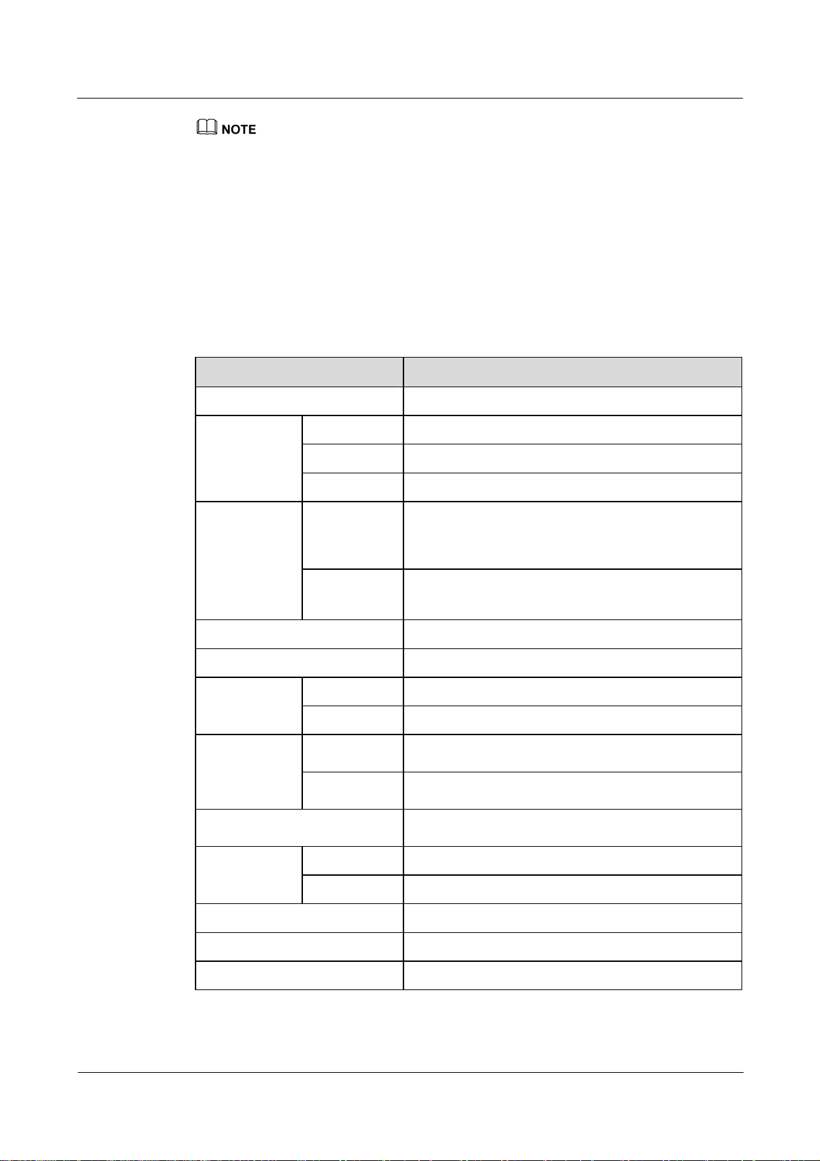
Table 1-2 System configuration data
Item Secure Router 8012
Number of slots 12
Maximum number of
interface boards
Fan backup Redundancy backup 2 x 4
Power backup DC or AC power supply modules in 1+1 redundancy
Fixed interface 1 AUX port
CPU PowerPC 7447
Boot ROM 512 KB x 2
SDRAM 512 MB (default), can be expanded to 2 GB
NVRAM 512 KB
Flash 64 MB
Packet transmission rate 6 Mpps
8
backup
1 console port
One 10/100/1000Base-TX Ethernet interface
Two 100/1000M Ethernet interfaces
967 MHz
Switching capacity 16 Gbit/s
Transmission attribute 1Gigabit Ethernet (GE) wire speed transmission
Mean Time Between Failure
(MTBF)
Mean Time To Repair
(MTTR)
Availability More than 0.99999
Issue 5.3 (6 April 2009) Nortel Networks Inc. 1-5
More than 34.34 years
Less than 60 minutes
Page 30
1 Overview
z
Synchronous Dynamic Random Access Memory (SDRAM) stores the communication data between
the system and CPU.
z
Non-Volatile Random Access Memory (NVRAM) stores critical files, such as the configuration files
and the record of the system running state.
z
Flash memory stores the operating system and the application program files.
z
Boot ROM stores the boot file for system startup.
1.3.2 Physical specifications
The following table describes the physical specifications of the Secure Router 8012.
Table 1-3 Physical specifications
Item Secure Router 8012
Cabinet structure Integrated cabinet, 6 U high
Nortel Secure Router 8012
Hardware Description
Dimension
Height (H) 263.9 mm
Width (W) 436.2 mm
Depth (D) 480.0 mm
Input voltage
AC Rated voltage range: 100 V AC to 240 V AC, 50/60Hz
Maximum voltage range: 90 V AC to 264 V AC,
50/60Hz
DC Rated voltage range: –48 V DC
Maximum voltage range: –72 V DC to –36 V DC
Maximum configuration weight 32 kg
Maximum power consumption 320 watts (W)
RPU 30 W Module
consumption
NPU 58 W
Operating
Long term
0℃ to 45℃
temperature
Short term
Storage temperature
–5℃ to 55℃
–40℃ to 70℃
Long term 5% RH to 85% RH (non-condensing) Relative
humidity (RH)
Short term 0% RH to 95% RH (non-condensing)
Storage relative humidity 0% RH to 95% RH
Long-term operating altitude < 3000 meters (m)
Storage altitude < 5000 m
1-6 Nortel Networks Inc. Issue 5.3 (6 April 2009)
Page 31

Nortel Secure Router 8012
Hardware Description 1 Overview
z
The temperature and humidity are measured at 1.5 m over the floor and 0.4 m in front of the cabinet.
There should be no protection board at the front or back of the cabinet.
z
Short-term operation means that the continuous working time does not exceed 48 hours and the
accumulated time per year does not exceed 15 days.
Issue 5.3 (6 April 2009) Nortel Networks Inc. 1-7
Page 32

Nortel Secure Router 8012
Hardware Description
Contents
2 Power supply ..............................................................................................................................2-1
2.1 Appearance and front panel...........................................................................................................................2-2
2.1.1 Appearance...........................................................................................................................................2-2
2.1.2 Front panel...........................................................................................................................................2-2
2.2 Functions.......................................................................................................................................................2-4
2.3 T ec hnical specifications ................................................................................................................................2-5
Issue 5.3 (6 April 2009) Nortel Networks Inc. i
Page 33

Page 34

Nortel Secure Router 8012
Hardware Description
Figures
Figure 2-1 Appearance of the AC power supply module....................................................................................2-2
Figure 2-2 Appearance of the DC power supply module...................................................................................2-2
Figure 2-3 Front panel of the AC power module................................................................................................2-2
Figure 2-4 Front panel of the DC power module ...............................................................................................2-3
Issue 5.3 (6 April 2009) Nortel Networks Inc. iii
Page 35

Page 36

Nortel Secure Router 8012
Hardware Description
Tables
Table 2-1 Relationship of the terminal block connection of the power input cable............................................2-3
Table 2-2 Description of the indicators on the AC power supply module..........................................................2-3
Table 2-3 Description of the indicators on the DC power supply module..........................................................2-4
Table 2-4 Technical specificationss of the power module ..................................................................................2-5
Issue 5.3 (6 April 2009) Nortel Networks Inc. v
Page 37

Page 38

Nortel Secure Router 8012
Hardware Description 2 Power supply
2 Power supply
About this chapter
The following table shows the contents of this chapter.
Title Description
2.1 Appearance and front
panel
2.2 Functions This section describes the functions of the power module.
2.3 Technical specifications This section describes the technical specifications of the
This section describes the appearance and the front panel
of the power module.
power module.
Issue 5.3 (6 April 2009) Nortel Networks Inc. 2-1
Page 39

2 Power supply
2.1 Appearance and front panel
2.1.1 Appearance
The Secure Router 8012 provides two types of power module: AC input and DC input. Figure
2-1 shows the appearance of the A C pow er module.
DC power module.
Figure 2-1 Appearance of the AC power supply module
AC O
ALM
RUN
K
Figure 2-2 Appearance of the DC power supply module
Nortel Secure Router 8012
Hardware Description
Figure 2-2 shows the appearance of the
2.1.2 Front panel
Figure 2-3 shows the appearance of the front panel of the AC power module. Figure 2-4
shows the appearance of the front panel of the DC power module.
Figure 2-3 Front panel of the AC power module
100-240V
100-240V
2-2 Nortel Networks Inc. Issue 5.3 (6 April 2009)
Page 40

Nortel Secure Router 8012
Hardware Description 2 Power supply
Figure 2-4 Front panel of t he DC power m odule
-48~-60V
-48~-60V
Table 2-1 Relationship of the terminal block connection of the power input cable
Identifier of the
terminal block
RTN (+) Power grounding
Input cable name Input cable color Input cable
interface
Black
Core end terminal
cable
NEG (-) Power cable Blue
PGND
NOTE
z
RTN: Ret urn
z
NEG: Negative
z
PGND: Protection Ground
Protection
grounding cable
Yellow and green Need not be
connected.
As shown in
Table 2-2 and Table 2-3, you can view the running state of the power module on
the indicators of the Routing Process Unit (RPU) front panel.
Table 2-2 Description of the indicators on the AC power supply module
Name Color Description
AC OK Green The power module input LED (only for the AC power
module).
Constant ON means the voltage input is normal (100 V
to 240 V), and OFF means the voltage input is not
normal.
RUN Green The power module indicators.
Constant ON means the power module runs normally,
and OFF means the power module has faults.
ALM Red The power module fault indicator.
Constant ON means the power module has faults or is
not in position.
Issue 5.3 (6 April 2009) Nortel Networks Inc. 2-3
Page 41

2 Power supply
Nortel Secure Router 8012
Hardware Description
Table 2-3 Description of the indicators on the DC power supply module
Indicator Color Description
DC OK Green The DC input state indicator (only for the DC power
module).
Constant ON means the voltage input is normal (-48 V
to -60 V), and OFF means the voltage input is not
normal.
RUN Green The power module LED.
Constant ON means the power module runs normally,
and OFF means the power module has faults.
ALM Red The power module failure LED.
Constant ON means the power module has faults or is
not in position.
The running state of the power module is available from the indicators on the RPU front panel.
For more information, see Chapter 4, “Boards.”
2.2 Functions
On the Secure Router 8012, the two types of power modules (AC input and DC input) are
inserted into the backplane from the back.
In normal situations, two power modules work in 1+1 hot backup mode. The AC and DC
power modules are the PSR550-A and the PSR550-D respectively. The power line uses the
–48V feeder cable of D 3PIN.
The power module has the following functions:
z
z
z
If you want to install a Secure Router 8012 in the communication equipment room, make sure that the
power distribution cabinet can provide a lightning protection box or arrester against the current of 20 KA
and above.
When power input is interrupted or an error occurs with one power module, the other
module is not affected and can provide power to the entire system. If the system needs to
be powered off, you must power off all the configured power modules.
The power module provides protection functions, including input over-voltage protection,
input under-voltage protection, output over-flow protection, output over-voltage
protection, output short-circuit protection, and over-heat protection.
The power module supports the hot swap feature. Switching the power module does not
affect the running system.
2-4 Nortel Networks Inc. Issue 5.3 (6 April 2009)
Page 42

Nortel Secure Router 8012
Hardware Description 2 Power supply
2.3 Technical specifications
The following table describes the technical specifications of the power module.
Table 2-4 Technical specificationss of the power module
Item Technical specifications
Dimensions 40.14 mm (H) x 350.00 mm (W) x 224.30 mm (D)
Weight 1.5 kg
Input rated
voltage
Input voltage
Maximum
input current
Input surge
current
output current
Input surge current 36 A
Maximum output current 60 A (3.3 V) 20 A (5 V) 30 A (12 V)
Maximum output power 550 W
AC 100 V AC to 240 V AC
50/60 Hz
DC –48 V DC to –60 V DC
AC 85 V AC to 264 V AC
50/60 Hz
DC –36V DC to –72V DC
AC 10 A Maximum
DC 25 A
Issue 5.3 (6 April 2009) Nortel Networks Inc. 2-5
Page 43

Nortel Secure Router 8012
Hardware Description
Contents
3 Heat dissipation system............................................................................................................3-1
3.1 Appearance and front panel...........................................................................................................................3-2
3.1.1 Appearance...........................................................................................................................................3-2
3.1.2 Front panel...........................................................................................................................................3-2
3.2 Functions.......................................................................................................................................................3-3
3.3 T ec hnical specifications ................................................................................................................................3-4
Issue 5.3 (6 April 2009) Nortel Networks Inc. i
Page 44

Page 45

Nortel Secure Router 8012
Hardware Description
Figures
Figure 3-1 Appearance of the fan in the Secure Router 8012.............................................................................3-2
Figure 3-2 Appearance of the fan front panel of the Secure Router 8012..........................................................3-3
Figure 3-3 Air flow inside the Secure Router 8012............................................................................................3-4
Issue 5.3 (6 April 2009) Nortel Networks Inc. iii
Page 46

Page 47

Nortel Secure Router 8012
Hardware Description
Tables
Table 3-1 Description of the fan module indicators............................................................................................3-3
Table 3-2 Technical specifications of the fan module.........................................................................................3-4
Issue 5.3 (6 April 2009) Nortel Networks Inc. v
Page 48

Page 49

Nortel Secure Router 8012 Hardware Description 3 Heat dissipation system
3 Heat dissipation system
About this chapter
The following table lists the contents of this chapter.
Title Description
3.1 Appearance and front
panel
3.2 Functions This section describes the functions of the heat dissipation
3.3 Technical specifications This section describes the technical specifications of the
The Secure Router 8012 heat dissipation system consists of the following components:
z
fan module
z
air filter
The air filter and the fan module are placed separately. The air filter is located to the right of
the cabinet backplane. You can clean the air filter by removing it from the back of the cabinet.
For information about replacing and cleaning the air filter, see Nortel Secure Router 8012 –
Installation (NN46240-301).
This chapter describes the fan function, appearance, front panel, and technical specifications
for the Secure Router 8012.
This section describes the appearance and the front panel
of the heat dissipation system.
system.
heat dissipation system.
Issue 5.3 (6 April 2009) Nortel Networks Inc. 3-1
Page 50

3 Heat dissipation system
3.1 Appearance and front panel
3.1.1 Appearance
The fan of the Secure Router 8012 is located to the left of the cabin backplane. It ventilates
the panel and dissipates heat. The fan supports hot swapping.
Nortel Secure Router 8012
Hardware Description
The fan module contains the fan frame and the fan components.
appearance of the fan module.
Figure 3-1 Appearance of the fan in the Secure Router 8012
Figure 3-1 shows the
3.1.2 Front panel
Figure 3-2 shows the fan module front panel.
3-2 Nortel Networks Inc. Issue 5.3 (6 April 2009)
Page 51

Nortel Secure Router 8012
Hardware Description 3 Heat dissipation system
Figure 3-2 Appearance of the fan front panel of the Secure Router 8012
FAN
Don’t use this handle
to lift subrack
CAUTION
DO NOT
TOUCH TH E
FAN LE AVE S
BEFORE THEY
SLOW DOWN
The warning indicators for the state of the fan module are located on the Routing Process Unit
(RPU) front panel.
Table 3-1 Description of the fan module indicators
Name Color Description
ALM
3.2 Functions
The revolution of the fan module is controlled by the RPU. Properly working fans keep the
Secure Router 8012 operating at the normal temperature. The fan module functions include
the following:
z
z
z
Table 3-1 describes the fan module indicators on the RPU.
Green Constant ON means the fan is operating normally. RUN
Red ON means an error occurred on the fan.
The fan module can modify the revolution automatically. It configures two parameters,
the low-temperature threshold and the high-temperature threshold. The low-temperature
threshold and the high-temperature threshold correspond with revs of 100% and 50%
respectively. For temperature operation requirements, see Chapter 1, “Overview.”
As the failure of one fan does not affect the operation of other fans, the system can still
operate at the normal temperature.
The system sends out rotation stop alarm signals if any fan fails.
Issue 5.3 (6 April 2009) Nortel Networks Inc. 3-3
Page 52

3 Heat dissipation system
The heat dissipation system of the Secure Router 8012 ventilates the Secure Router 8012.
From the top, the air flow enters the Secure Router 8012 from the left and exits from the right.
Figure 3-3 shows the air flow inside the Secure Router 8012.
Figure 3-3 Air flow inside the Secure Router 8012
Nortel Secure Router 8012
Hardware Description
3.3 Technical specifications
Table 3-2 shows the technical specifications of the fan module.
Table 3-2 Technical specifications of the fan module
Item Specifications
Dimensions 259.45 mm (H) x 47.70 mm (W) x 462.65 mm (D)
Power consumption 38.4 W
Maximum blast pressure 75 Pa
Maximum blast volume 921.6 m3/h
Maximum noise 60 dB
Maximum rev 3800 RPM
Fan module frame
Operating voltage range 7.0 V to 13.8 V DC
Operating voltage 12 V DC
3-4 Nortel Networks Inc. Issue 5.3 (6 April 2009)
Page 53

Nortel Secure Router 8012
Hardware Description
Contents
4 Boards...........................................................................................................................................4-1
4.1 Introduction...................................................................................................................................................4-3
4.1.1 Board classification and slot arrangement...........................................................................................4-3
4.1.2 Logical relationship among boards......................................................................................................4-7
4.1.3 Board appearance.................................................................................................................................4-8
4.1.4 Interface types and distribution on the boards ...................................................................................4-10
4.2 RPUs...........................................................................................................................................................4-12
4.2.1 Functions............................................................................................................................................4-12
4.2.2 Front panel.........................................................................................................................................4-13
4.2.3 Interfaces............................................................................................................................................4-15
4.2.4 Interface attributes .............................................................................................................................4-15
4.2.5 Technical specifications.....................................................................................................................4-17
4.3 NPUs...........................................................................................................................................................4-17
4.3.1 Functions............................................................................................................................................4-17
4.3.2 Front panel.........................................................................................................................................4-18
4.3.3 Technical specifications.....................................................................................................................4-18
4.4 10/100Base-TX electrical interface module................................................................................................4-19
4.4.1 Functions............................................................................................................................................4-19
4.4.2 Front panel.........................................................................................................................................4-19
4.4.3 Interface attributes .............................................................................................................................4-20
4.5 100Base-FX Ethernet optical interface module...........................................................................................4-20
4.5.1 Functions............................................................................................................................................4-21
4.5.2 Front panel.........................................................................................................................................4-21
4.5.3 Interface attributes .............................................................................................................................4-22
4.6 1000Base-X Ethernet optical interface module...........................................................................................4-22
4.6.1 Functions............................................................................................................................................4-23
4.6.2 Front panel.........................................................................................................................................4-23
4.6.3 Interface attributes .............................................................................................................................4-23
4.7 Channelized and unchannelized E1/T1 interface module ...........................................................................4-25
4.7.1 Functions............................................................................................................................................4-25
4.7.2 Front panel.........................................................................................................................................4-26
4.7.3 Interface attributes .............................................................................................................................4-28
Issue 5.3 (6 April 2009) Nortel Networks Inc. i
Page 54

Nortel Secure Router 8012
4.8 Channelized E3 interface modules..............................................................................................................4-29
4.8.1 Functions............................................................................................................................................4-29
4.8.2 Front panel.........................................................................................................................................4-29
4.8.3 Interface attributes .............................................................................................................................4-30
4.9 Synchronous serial port module..................................................................................................................4-30
4.9.1 Functions............................................................................................................................................4-30
4.9.2 Front panel.........................................................................................................................................4-32
4.9.3 Interface attributes .............................................................................................................................4-32
4.10 Channelized and unchannelized POS optical interface modules...............................................................4-33
4.10.1 Functions..........................................................................................................................................4-33
4.10.2 Front panel.......................................................................................................................................4-34
4.10.3 Interface attributes ...........................................................................................................................4-35
4.11 HSSI interface module..............................................................................................................................4-35
4.11.1 Functions..........................................................................................................................................4-35
4.11.2 Front panel .......................................................................................................................................4-36
4.11.3 Interface attributes............................................................................................................................4-36
4.12 IPSec encryption HIC module...................................................................................................................4-37
4.12.1 Function...........................................................................................................................................4-37
4.12.2 Front panel.......................................................................................................................................4-37
4.12.3 Module attributes.............................................................................................................................4-38
Hardware Description
ii Nortel Networks Inc. Issue 5.3 (6 April 2009)
Page 55

Nortel Secure Router 8012
Hardware Description
Figures
Figure 4-1 Arrangement of the Secure Router 8012 slots on the backplane (front view) ..................................4-4
Figure 4-2 Arrangement of the Secure Router 8012 slots on the backplane (rear view)....................................4-5
Figure 4-3 Logical relationship among the boards of a Secure Router 8012 .....................................................4-8
Figure 4-4 Components on an RPU....................................................................................................................4-9
Figure 4-5 Components on an NPU board .........................................................................................................4-9
Figure 4-6 Components on an HIC/FIC...........................................................................................................4-10
Figure 4-7 Appearance of the RPU front panel................................................................................................4-13
Figure 4-8 Appearance of the NPU front panel................................................................................................4-18
Issue 5.3 (6 April 2009) Nortel Networks Inc. iii
Page 56

Page 57

Nortel Secure Router 8012
Hardware Description
Tables
Table 4-1 Working modes of the Secure Router 8012........................................................................................4-5
Table 4-2 Allowed HICs in different modes of the Secure Router 8012............................................................4-6
Table 4-3 Board dimensions.............................................................................................................................4-10
Table 4-4 Interface distribution on the boards ..................................................................................................4-10
Table 4-5 Description of the components on the front panel of an RPU..........................................................4-13
Table 4-6 The interfaces on the RPU and their usage.......................................................................................4-15
Table 4-7 Console interface attributes ..............................................................................................................4-15
Table 4-8 AUX interface attributes...................................................................................................................4-16
Table 4-9 Attributes of the 10/100/1000M Ethernet interface..........................................................................4-16
Table 4-10 Attributes of the 100/1000M Ethernet interface.............................................................................4-16
Table 4-11 T echnical specifications of the RPU...............................................................................................4-17
Table 4-12 Description of the NPU indicators..................................................................................................4-18
Table 4-13 Description of the NPU technical specifications ............................................................................4-19
Table 4-14 Description of the 10/100Base-TX Ethernet electrical interface module.......................................4-19
Table 4-15 Description of indicators of the 10/100Base-TX Ethernet electrical interface module ..................4-20
Table 4-16 Attributes of the 10/100Base-TX Ethernet electrical interface module..........................................4-20
Table 4-17 Description of the 100Base-FX Ethernet optical interface module................................................4-21
Table 4-18 Description of the indicators of the 100Base-FX Ethernet optical interface module .....................4-21
Table 4-19 Attributes of the 100Base-FX Ethernet optical interface................................................................4-22
Table 4-20 Attributes of the 100Base-FX Ethernet interface SFP optical module............................................4-22
Table 4-21 Description of the 1000Base-X Ethernet optical interface module ................................................4-23
Table 4-22 Description of the indicators of the 1000Base-X Ethernet optical interface module......................4-23
Table 4-23 Attributes of the 1000Base-X Ethernet optical interface module...................................................4-23
Table 4-24 Attributes of the 1000Base-X Ethernet interface SFP optical module............................................4-24
Table 4-25 Attributes of SFP electrical interface module of 1000Base-X Ethernet interface...........................4-24
Table 4-26 Description of the channelized and unchannelized E1 interface modules......................................4-26
Issue 5.3 (6 April 2009) Nortel Networks Inc. v
Page 58

Nortel Secure Router 8012
Table 4-27 Description of the channelized T1 interface modules.....................................................................4-27
Table 4-28 Description of the indicators of channelized and unchannelized E1/T1 interface modules............4-28
Table 4-29 Attributes of the channelized and unchannelized E1/T1 interface modules ...................................4-28
Table 4-30 Description of the channelized E3 interface module......................................................................4-29
Table 4-31 Description of the indicators of the channelized E3 interface module ...........................................4-29
Table 4-32 Attributes of the channelized E3 interface module.........................................................................4-30
Table 4-33 Typical DTE and DCE devices.......................................................................................................4-31
Table 4-34 V.24/V.35 cable rate and transmission distance..............................................................................4-31
Table 4-35 Description of the synchronous serial port module ........................................................................4-32
Table 4-36 Description of the indicators of a synchronous serial port module.................................................4-32
Table 4-37 Attributes of the 4SAE interface module........................................................................................4-32
Table 4-38 Description of channelized and unchannelized POS optical interface modules .............................4-34
Table 4-39 Description of the indicators on the front panel of POS optical interface modules........................4-35
Hardware Description
Table 4-40 Attributes of channelized and unchannelized POS optical interface modules................................4-35
Table 4-41 Description of the HSSI front panel ...............................................................................................4-36
Table 4-42 Description of the indicators of the HSSI front panel.....................................................................4-36
Table 4-43 Attributes of the HSSI interface module.........................................................................................4-37
Table 4-44 Front panel of an IPSec encryption HIC module............................................................................4-37
Table 4-45 Description of the indicators of an IPSec encryption HIC module.................................................4-37
Table 4-46 Attributes of the IPSec encryption HIC module.............................................................................4-38
vi Nortel Networks Inc. Issue 5.3 (6 April 2009)
Page 59

Nortel Secure Router 8012
Hardware Description 4 Boards
4 Boards
About this chapter
The following table shows the contents of this chapter.
Title Description
4.1 Introduction This section describes the classification of boards by
their function and the models of each type of board;
the slots where the boards are inserted; the logical
relationship between boards; the appearance of
boards; and the classification of boards by interface.
4.2 RPUs This section describes the functions, front panel,
interfaces, and technical specifications of the Routing
Process Unit (RPU).
4.3 NPUs This section describes the functions, panel, and
technical specifications of the Network Process Unit
(NPU).
4.4 10/100Base-TX electrical
interface module
4.5 100Base-FX Ethernet optical
interface module
4.6 1000Base-X Ethernet optical
interface module
This section describes the functions and front panel of
the 10/100Base-TX electrical interface module, and
the attributes of the interfaces.
This section describes the functions and front panel of
the 100Base-FX Ethernet optical interface module,
and the attributes of the interfaces.
This section describes the functions and front panel of
the 1000Base-X Ethernet optical interface module,
and the attributes of the interfaces.
4.7 Channelized and
unchannelized E1/T1 interface
module
4.8 Channelized E3 interface
modules
Issue 5.3 (6 April 2009) Nortel Networks Inc. 4-1
This section describes the functions and front panel of
the channelized and unchannelized E1/T1 interface
module, and the attributes of the interfaces.
This section describes the functions and front panel of
the channelized E3 interface module, and the
attributes of the interfaces.
Page 60

4 Boards
Nortel Secure Router 8012
Hardware Description
Title Description
4.9 Synchronous serial port
module
This section describes the functions and front panel of
the synchronous serial port module, and the attributes
of the interfaces.
4.10 Channelized and
unchannelized POS optical
interface modules
This section describes the functions and front panel of
the channelized and unchannelized Packet Over
SDH/SONET (POS) optical interface module, and the
attributes of the interfaces.
4.11 HSSI interface module This section describes the functions and front panel of
the High Speed Serial Interface (HSSI) interface
module, and the attributes of the interfaces.
4.12 IPSec encryption HIC
module
This section describes the functions and front panel of
the IP Security (IPSec) encryption High-speed
Interface Card (HIC), and the attributes of the
module.
4-2 Nortel Networks Inc. Issue 5.3 (6 April 2009)
Page 61

Nortel Secure Router 8012
Hardware Description 4 Boards
4.1 Introduction
This section describes the Secure Router 8012 boards, including board classification, slot
arrangement, board appearance, interface type, and interface distribution.
4.1.1 Board classification and slot arrangement
Board classification
The Secure Router 8012 supports the following board types:
z
Routing Process Unit (RPU)
z
Network Process Unit (NPU)
z
Flexible Interface Card (FIC), including:
− 4-port multiprotocol synchronous serial interface module (4SAE)
− 4-port unchannelized E1 module (4E1)
− 4-port channelized E1 module (4CE1)
− 8-port unchannelized E1 module (8E1)
− 8-port channelized E1 module (8CE1)
− 1-port channelized E3 module (1CE3)
− 4-port channelized T1 module (4CT1)
− 8-port channelized T1 module (8CT1)
− 1-port channelized POS optical interface module (1CPOS[E])
− 1-port HSSI interface module (1HSSI)
− 2-port HSSI interface module (2HSSI)
The Secure Router 8012 with the host software version VRP5.30-23134002 or later supports the HSSI
interface.
z
High-speed Interface Card (HIC), including:
− 2-Port 100M Ethernet High Speed Electrical Interface Card (RJ45)for Secure Router
8002, 8004, and 8008 (2xFE UTP)
− 4-Port 100M Ethernet High Speed Electrical Interface Card (RJ45) for Secure Router
8002, 8004, and 8008 (4xFE UTP)
− 8-port 100M Ethernet High Speed Electrical interface Card (RJ45)for Secure Router
8002, 8004, and 8008 (8xFE UTP)
− 2-Port Fast Ethernet High Speed Optical Interface Card (SFP) for Secure Router 8002,
8004, and 8008 (2xFE Optical )
− 4-Port Fast Ethernet High Speed Optical Interface Card (SFP) for Secure Router 8002,
8004, and 8008 (4xFE Optical)
− 8-Port Fast Ethernet High Speed Optical Interface Card (SFP) for Secure Router 8002,
8004, and 8008 (8xFE Optical)
− High Speed 1-port 1000M Ethernet card(SFP) for Secure Router 8002, 8004, and
8008 (1xGig E (SFP))
− High Speed 2-port 1000M Ethernet card(SFP) for Secure Router 8002, 8004, and
8008 (2xGig E (SFP))
Issue 5.3 (6 April 2009) Nortel Networks Inc. 4-3
Page 62

4 Boards
Nortel Secure Router 8012
Hardware Description
− High Speed 1-port 155M POS card(SFP) for Secure Router 8002, 8004, and 8008
(1x155 POS)
− High Speed 2-port 155M POS card(SFP) for Secure Router 8002, 8004, and 8008
(2x155 POS)
− High Speed 4-port 155M POS card(SFP) for Secure Router 8002, 8004, and 8008
(4x155 POS)
− 1-port OC-3/STM-1 CPOS-Channelized E1 Optical Interface Board(SFP) for Secure
Router 8012 (1xOC3/STM1 ATM(SFP))
− 1-port OC-3/STM-1 CPOS-Channelized T1-Optical Interface Board(SFP)
(1xOC3/STM1 CPOSCT1 (SFP))
− 16-port Channelized E1-DB78-75ohm,Interface Board for Secure Router 8012
(16xCE1 DB78 75ohm)
− 16-port Channelized T1-DB78-120ohm,Interface Board for Secure Router 8012
(16xCT1 DB78 120ohm)
− 1-port OC-3/STM-1 ATM High Speed Optical Interface Board(SFP) for Secure
Router 8012 (1xOC3/STM1 ATM(SFP))
− 2-port OC-3/STM-1 ATM High Speed Optical Interface Board(SFP) for Secure
Router 8012 (2xOC3/STM1 ATM(SFP))
− 4-port OC-3/STM-1 ATM (HIC) High Speed Optical Interface Board(SFP) for Secure
Router 8012 (4xOC3/STM1 ATM (HIC) (SFP))
− 1-port 155M POS (HIC) High Speed Optical Interface Board(SFP) for Secure Router
8012 (1xSTM1/POS-SFP-HIC-SR8012)
− 2-port 155M POS (HIC) High Speed Optical Interface Board(SFP) for Secure Router
8012 (2xSTM1/POS-SFP-HIC-SR8012)
− 4-port 155M POS (HIC) High Speed Optical Interface Board(SFP) for Secure Router
8012 (4xSTM1/POS-SFP-HIC-SR8012)
− IPSEC High Speed Interface Board for Secure Router 8002, 8004, and 8008 (IPSec
Module)
Slot arrangement
Figure 4-1 shows the board slots of the Secure Router 8012.
Figure 4-1 Arrangement of the Secure Router 8012 slots on the backplane (front view)
FIC
FIC
FIC
HIC/FIC
RPU
RPU
FIC
FIC
HIC/FIC
HIC/FIC
10
9
7
8
56
34
12
4-4 Nortel Networks Inc. Issue 5.3 (6 April 2009)
Page 63

Nortel Secure Router 8012
Hardware Description 4 Boards
Figure 4-2 Arrangement of the Secure Router 8012 slots on the backplane (rear view)
NPU2
NPU1
FAN
PWR2
PWR1
You can insert the RPU into slots 9 and 10 on the top of the front panel of the chassis. You can
insert the NPU into the two slots on the top of the rear panel of the chassis. The slots for
NPUs and RPUs are positioned back to back.
You can insert an FIC into any of the slots 1 to 8.
You can insert an HIC into any of the slots 1, 2, 3, 4, 5, and 7. The type of HIC, however, is
determined by the working mode of the router.
The Secure Router 8012 can operate in two modes: ordinary mode and extended mode. For
information about the differences between the two modes, see
Before hot swapping, run the preplug slot Existing slot number command in the system view.
When information appears indicating that hot swapping is permitted, you can insert or remove
boards. Nortel recommends that you substitute the same type of boards during hot swapping.
z
To switch from ordinary mode (3HIC) to extended mode (6HIC), first remove the
non-extendable HIC from slot 1. Otherwise, you cannot switch from ordinary mode to
extended mode.
z
To switch from extended mode (6HIC) to ordinary mode (3HIC), first remove the
extendable HICs from slots 1, 3, 5, and 7. Otherwise, you cannot switch from extended
mode to ordinary mode.
Table 4-1 Working modes of the Secure Router 8012
Table 4-1.
Working mode Condition
Ordinary One of the following HICs is inserted in slot 1: 2xFE UTP, 4xFE
UTP, 8xFE UTP, 2xFE UTP, 4xFE UTP, 8xFE Optical, 1xGig E
(SFP), 2xGig E (SFP), 2x155 POS, 4x155 POS, 2xOC3/STM1,
4xOC3/STM1 ATM (HIC) (SFP), or IPSec Module.
Issue 5.3 (6 April 2009) Nortel Networks Inc. 4-5
Page 64

4 Boards
Nortel Secure Router 8012
Hardware Description
Working mode Condition
Extended One of the following HICs is inserted in any of the slots 1, 3, 5, and 7:
16xCE1 DB78 75ohm, 16xCT1 DB78 120ohm, 1xOC3/STM1
CPOSCE1(SFP), 1xOC3/STM1 CPOSCT1 (SFP), 1xOC3/STM1
ATM(SFP), or 1x155 POS HIC.
Based on the working mode, the slots allow different HICs, as shown in
Table 4-2 Allowed HICs in different modes of the Secure Router 8012
Slot number Working
mode
1 2 and 4 3, 5, and 7 6 and 8
Ordinary
(3 HICs)
Any of the
following HICs:
2xFE UTP
Any of the
HICs or FICs
Any of the
FICs, but not
HICs
SR8002/4/8
4xFE UTP
SR8002/4/8
8xFE UTP
2xFE UTP-SFP
SR8002/4/8
4xFE UTP-SFP
SR8002/4/8
8xFE Optical
1xGig E (SFP)
2xGig E (SFP)
2x155 POS
4x155 POS
2xOC3/STM1
4xOC3/STM1
ATM (HIC)
(SFP)
IPSec Module
Table 4-2.
Any of the
FICs, but not
HICs
Extended
(6 HICs)
4-6 Nortel Networks Inc. Issue 5.3 (6 April 2009)
Any of the
following HICs:
16xCE1 DB78
75ohm
16xCT1 DB78
120ohm
1xOC3/STM1
CPOSCE1(SFP)
1xOC3/STM1
CPOSCT1
(SFP)
Any of the
HICs or FICs
Any of the
FICs, or any of
the following
HICs:
16xCE1 DB78
75ohm
16xCT1 DB78
120ohm
1xOC3/STM1
CPOSCE1(SFP)
1xOC3/STM1
Any of the
FICs, but not
HICs
Page 65

Nortel Secure Router 8012
Hardware Description 4 Boards
Slot number Working
mode
1 2 and 4 3, 5, and 7 6 and 8
1xOC3/STM1
ATM(SFP)
1x155 POS
During initialization, the system mode is determined as follows: The router scans slot 1, 3, 5, and 7 in
sequence; when the first HIC is found, the router determines the system working mode according to the
card type; in the successive scanning, if the router finds that an HIC in a slot breaks the card mixture rule,
the slot is marked as ABNORMAL and is not initialized.
During hot swapping, the system mode is determined as follows: The router detects whether the type of
card that is inserted into slot 1, 3, 5, or 7 conflicts with the current system mode; if yes, the slot is
marked as ABNORMAL and is not initialized.
4.1.2 Logical relationship among boards
Figure 4-3 shows the logical relationship among the boards of a Secure Router 8012.
CPOSCT1
(SFP)
1xOC3/STM1
ATM(SFP)
1x155 POS
Issue 5.3 (6 April 2009) Nortel Networks Inc. 4-7
Page 66

4 Boards
Nortel Secure Router 8012
Hardware Description
Figure 4-3 Logical relationship among the boards of a Secure Ro uter 8 012
Console
Physical interface module
RPU
(Slave)
Comm. management module
PCI0 PCI1
Odd-
numbered
slots
FIC
... ...
PCI0 PCI1PCI1
Comm. management module
AUX 2GE
Processor module
Even-
numbered
FIC FIC FIC HIC HIC HIC HIC
slots
NPU
(Slave)
Comm. management module
Comm. management module
NPU module
RPU
(Master)
Physical interface module
Console AUX 2GE
4.1.3 Board appearance
Wear an electrostatic discharge (ESD)-preventive wrist strap and keep it well grounded
whenever you touch the board to prevent the ESD from damaging the board.
Processor module
NPU
(Master)
NPU module
4-8 Nortel Networks Inc. Issue 5.3 (6 April 2009)
Page 67

Nortel Secure Router 8012
Hardware Description 4 Boards
Do not let your eyes near or stare at the optical interface or the fiber interface. The laser beam
is harmful to your eyes.
Figure 4-4, Figure 4-5, and Figure 4-6 show the appearance of the RPU, NPU, and HIC/FIC,
using the the 8FE as an example.
Figure 4-4 Components on an RPU
12
P
P
W
W
R
R
2
1
911
78101213
7
3
6
45
1. Connector 2.Guiding jack 3.Board
4.Board silkscreen 5. Handle 6. Reserved interface
7. 100/1000M Ethernet interface 8. CONSOLE port 9. AUX port
10. 10/100/1000M Ethernet interface 11. Reset key 12. Indicator
13. Captive screw
Figure 4-5 Components on an NPU board
1. Connector 2. Board silkscreen 3. Handle
4. Board 5. Indicator 6. Captive screw
Issue 5.3 (6 April 2009) Nortel Networks Inc. 4-9
Page 68

4 Boards
Nortel Secure Router 8012
Hardware Description
Figure 4-6 Components on an HIC/FIC
1. Connector 2. Front panel 3. Captive screw
4. Handle 5. Interface 6. Board silkscreen
Table 4-3 shows the board dimensions.
Table 4-3 Board dimensions
Name Dimensions
RPU 399.15 mm (W) x 236 mm (D) x 35.06 mm (H)
NPU 372.45 mm (W) x 238 mm (D) x 35.06 mm (H)
HIC/FIC 198.55 mm (W) x 243.19 mm (D) x 40.14 mm (H)
4.1.4 Interface types and distribution on the boards
All interfaces are integrated on the board and imported from the board. Table 4-4 shows the
interface distribution on the boards.
Table 4-4 Interface distribution on the boards
Interface
classification
Optical
interface
Interface
name
100Base-FX
Ethernet
optical
interface
Interface attribute Interface
type
Single-mode optical
LC RT-HIC-2FE-
interface
Board name
SFP
RT-HIC-4FE-
SFP
RT-HIC-8FE-
SFP
Multi-mode optical
interface
LC RT-HIC-2FE-
SFP
RT-HIC-4FE-
SFP
RT-HIC-8FE-
SFP
4-10 Nortel Networks Inc. Issue 5.3 (6 April 2009)
Page 69

Nortel Secure Router 8012
Hardware Description 4 Boards
Interface
classification
Interface
name
1000Base
–FX Ethernet
optical
interface
FIC low-speed
155M ATM
optical
interface
HIC
high-speed
155M ATM
optical
interface
Interface attribute Interface
type
Single-mode optical
LC RT-HIC-1GE
interface
Single-mode long-haul
optical interface
Single-mode ultra
long-haul optical
interface
Multi-mode optical
interface
Single-mode optical
SC
interface
Single-mode long-haul
optical interface
Multi-mode optical
interface
Single-mode short-haul
LC RT-HIC-1AT
optical interface
Single-mode long-haul
optical interface
Single-mode ultra
long-haul optical
interface
Board name
RT-HIC-2GE
RPU
1ATM-OC3S
M
1ATM-OC3S
ML
1ATM-OC3M
M
M
RT-HIC-2AT
M
RT-HIC-4AT
M
Electrical
interface
POS optical
interface
10/100Base-T
X FE
electrical
Interface
Multi-mode optical
interface
Single-mode short-haul
optical interface
Single-mode long-haul
optical interface
Single-mode ultra
long-haul optical
interface
Multi-mode optical
interface
10M/100 Mbit/s
autosensing
LC 1CPOS(E)
RT-HIC-1PO
S
RT-HIC-2PO
S
RT-HIC-4PO
S
RT-HIC-CPE
1
RT-HIC-CPT
1
RJ45 RT-HIC-2FE
RT-HIC-4FE
RT-HIC-8FE
Issue 5.3 (6 April 2009) Nortel Networks Inc. 4-11
Page 70

4 Boards
Nortel Secure Router 8012
Hardware Description
Interface
classification
Interface
name
Serial port High-speed
synchronous
serial port
Electrical
interface of
Ethernet
interface
maintenance
Console
interface
AUX interface — RJ45 RPU
E1/CE1
T1/CT1
Interface attribute Interface
Board name
type
DTE/DCE DB-28 4SAE
10M/100M/1000M bit/s
RJ45 RPU
autosensing
— RJ45 RPU
z
75 Ω coaxial cable
z
120 Ω shielded
twisted pair (STP)
z
Coaxial
connecto
r
z
RJ45
4E1/4CE1/8E
1/8CE1
/RT-HIC-16C
E1
4CT1/8CT1/
RT-HIC-16C
T1
4.2 RPUs
This section introduces the functions of the Routing Process Unit (RPU), the boards, the
interfaces, and the technical specifications for the Secure Router 8012.
The RPU is located in either of the two slots on the top of the chassis. The RPU is installed in
the front panel and corresponds with the NPU in the system. The Secure Router 8012 has two
types of RPUs: ERPUA (with a memory of 512 MB) and ERPUB (with a memory of 1 GB).
For normal operation, the master RPU and slave RPU must be the same type.
4.2.1 Functions
The RPU is the main control board of the Secure Router 8012. It consists of the PowerPC
processor, system controller bridge, storage, and other attached devices. The RPU monitors
the system ports, manages the equipment, and processes various software protocols.
The RPU has the following functions:
z
z
z
z
z
z
z
z
processes the routing protocol
receives and sends the FIC packets
manages the interface state
monitors the state of the power system
monitors the state of the fan system
monitors the system temperature
supports the configuration and management of the active and standby NPUs
configures and manages the high-speed interface
4-12 Nortel Networks Inc. Issue 5.3 (6 April 2009)
Page 71

Nortel Secure Router 8012
Hardware Description 4 Boards
z
supports the active and standby switchover
z
supports hot swapping
z
supports the hot and cool backup
In addition, the RPU provides two Gigabit Ethernet (GE) ports. It supports the exclusion of
the optical function and the electrical function on the GE port; that is, you cannot use the
optical function and the electrical function on the GE port at the same time..
4.2.2 Front panel
Figure 4-7 shows the appearance of the panel. Table 4-5 describes the components.
Figure 4-7 Appearance of the RPU front panel
P
P
W
W
R
R
2
1
Table 4-5 Description of the components on the front panel of an RPU
Name Silkscreen Description
ALM (red)
SYS The system running LED, including the fan,
power supply, and NPU warnings. Constant ON
means the CPU received a warning.
NPU The NPU failure LED. Constant ON means the
NPU failed.
RPU (green)
RUN The system running LED. Blinking means the
CPU works normally. Constant ON or OFF
means the CPU failed.
MST The standby state LED. On means that the board
is the master RPU.
Issue 5.3 (6 April 2009) Nortel Networks Inc. 4-13
Page 72

4 Boards
Nortel Secure Router 8012
Hardware Description
Name Silkscreen Description
NPU1 (green)
NPU2 (green)
FAN
PWR1
RUN The system running LED. Blinking means the
CPU is in normal operation. Constant ON or
OFF means the CPU failed.
MST The standby state LED. On means that the board
is the master NPU.
RUN The system running LED. Blinking means the
CPU is in normal operation. Constant ON or
OFF means the CPU failed.
MST The standby state LED. On means that the board
is the master NPU.
PRN (green) The fan position LED. Constant ON means the
fan is in position or has failed.
ALM (red) The fan warning LED. Constant ON means the
fan is not in position or its rotation is obstructed.
PRN (green) The LED of the first power module in position.
Constant ON means the power module is in
position. Constant OFF means the power module
is not in position.
ALM (red) The first power module failure LED. Constant
ON means that the power module is disabled or
has failed.
PWR2
PRN (green) The LED of the second power module in
position. Constant ON means the power module
is in position. Constant OFF means the power
module is not in position.
ALM (red) The second power module failure LED. Constant
ON means that the power module is disabled or
has failed.
RESET The RPU hardware reset button, which is used to
restart the device.
10/100/1000M
Ethernet 0 LED
LINK (green) OFF means the link is not connected and ON
means the link is connected.
ACT (yellow) OFF means no data is being transmitted or
received on the interface, and blinking means
data is being transmitted and received.
100/1000M
Ethernet 1 LED
LINK (green) OFF means the link is not connected and ON
means the link is connected.
ACT (yellow) OFF means no data is being transmitted and
received on the interface, and blinking means
data is being transmitted and received.
100/1000M
Ethernet 2 LED
4-14 Nortel Networks Inc. Issue 5.3 (6 April 2009)
LINK (green) OFF means the link is not connected and ON
means the link is connected.
Page 73

Nortel Secure Router 8012
Hardware Description 4 Boards
Name Silkscreen Description
ACT (yellow) OFF means no data is being transmitted and
received on the interface, and blinking means
data is being transmitted and received.
4.2.3 Interfaces
Table 4-6 describes the interfaces on the RPU and their usage.
Table 4-6 The interfaces on the RPU and their usage
Item Description
Console port The local debugging serial port.
It is used to connect the serial port of a PC. The terminal emulation
program can run on the PC.
It can be used as the command line interface (CLI) and also for board
or system debugging, testing, serial port printing, background
operation, troubleshooting, and online upgrading.
AUX port The AUX port is also called the remote debugging physical interface.
10/100/1000M
Ethernet port
100/1000M
Ethernet port
Compact flash
card
4.2.4 Interface attributes
Table 4-7 shows the attributes of the console port.
Table 4-7 Console interface attributes
It provides remote configuration, connects the modem, and establishes
the connection with the remote router by dialing.
When faults occur on the console port, you can use the AUX port as
the console port.
Provides the remote logon Telnet function and can be used for board
or system debugging, testing, background operation, fault diagnosis,
online upgrading, and remote operation.
Similar to the 10/100/1000M Ethernet port, this port is used for
debugging.
Reserved as the interface.
Attribute Description
Connector type RJ45
Standard RS-232
Baud rate 9600 bit/s to 115 200 bit/s
Issue 5.3 (6 April 2009) Nortel Networks Inc. 4-15
Page 74

4 Boards
Nortel Secure Router 8012
Hardware Description
9600 bit/s by default
Table 4-8 shows the atttributes of the AUX port.
Table 4-8 AUX interface attributes
Attribute Description
Connector type RJ45
Standard Asynchronous EIA/TIA-232
Baud rate 300 bit/s to 115 200 bit/s
Supported
protocols
Point-to-Point Protocol (PPP)
Serial Line Internet Protocol (SLIP)
Multilink Protocol (MP)
Table 4-9 shows the attributes of the 10/100/1000M Ethernet port.
Table 4-9 Attributes of the 10/100/1000M Ethernet interface
Attribute Description
Connector type RJ45
Supported frame
format
Ethernet_II
Ethernet_SNAP
IEEE 802.2
IEEE 802.3
Operating mode 10/100/1000 Mbit/s autosensing
Full duplex
Half duplex
Supported
IP
network protocol
Table 4-10 shows the attributes of the 100/1000M Ethernet interface.
Table 4-10 Attributes of the 100/1000M Ethernet interface
Attribute Description
Connector type Small Form-Factor Pluggable (SFP) optical module
Number of
2 1
interfaces
Supported frame
Ethernet_II
format
4-16 Nortel Networks Inc. Issue 5.3 (6 April 2009)
Page 75

Nortel Secure Router 8012
Hardware Description 4 Boards
Attribute Description
Ethernet_SNAP
Working mode 100/1000 Mbit/s autosensing
Full duplex
Supported
network protocol
IP
4.2.5 Technical specifications
Table 4-11 shows the technical specifications of the RPU board.
Table 4-11 Technical specifications of the RPU
Parameter Description
Silkscreen RPU
Power consumption 35 W
Dimensions 399.15 mm (W) x 236 mm (D) x 35.06 mm (H)
Height of the front
panel
35.06 mm
4.3 NPUs
This section introduces the functions of the Network Process Unit (NPU), the board, and the
technical specifications for the Secure Router 8012.
The board is located in the back slot on the bottom of the chassis. An NPU is installed in the
system from the back and sits back-to-back with the RPU.
4.3.1 Functions
An NPU consists of the network processor module, the Field Programmable Gate Array
(FPGA) module, the storage module, and the other attached devi ces. The board implements
expedited forwarding of data packets, including IP forwarding, Multiprotocol Label Switching
(MPLS) forwarding, multicast forwarding, and Quality of Service (QoS). The forwarding rate
can reach 6 Mpps.
The NPU has the following functions:
z
z
z
inputs the service data convergence and outputs the service data division
provides the upstream and downstream of the data convergence module with the QoS
guarantee
encapsulates and decapsulates the data frame after HIC and FIC data enters the network
process module
Issue 5.3 (6 April 2009) Nortel Networks Inc. 4-17
Page 76

4 Boards
z
encapsulates and decapsulates the data frame after high-speed interface control packets
enter the network process module
z
periodically detects the state of the network process module and queries the board
version
z
updates the Erasable Programmable Logic Device (EPLD) and FPGA, and implements
the online loop and offline loop of FPGA in the board
z
monitors the temperature
z
supports resetting of the service interface board and other main modules
z
supports the CABwatch debugging tool provided by IBM
4.3.2 Front panel
Figure 4-8 shows the appearance of the NPU front panel.
Figure 4-8 Appearance of the NPU front panel
RUN
Nortel Secure Router 8012
Hardware Description
A
L
M
Table 4-12 describes the NPU indicators.
Table 4-12 Description of the NPU indicators
Component Description
RUN (green) The running LED. Blinking means the NPU works normally. Constant
OFF means the NPU is not in position or failed.
ALM (red) The alarm LED. Constant ON means NPU failed.
The NPU does not provide external interfaces.
4.3.3 Technical specifications
Table 4-13 describes the NPU technical specifications.
4-18 Nortel Networks Inc. Issue 5.3 (6 April 2009)
Page 77

Nortel Secure Router 8012
Hardware Description 4 Boards
Table 4-13 Description of the NPU technical specifications
Parameter Description
Silkscreen NPU
Power consumption 58 W
Dimension 372.45 mm (W) x 238 mm (D) x 35.06 mm (H)
Height of the front
35.06 mm
panel
4.4 10/100Base-TX electrical interface module
The 10/100Base-TX electrical interface modules of the Secure Router 8012 are as follows:
z
2-port 10/100Base-TX Fast Ethernet electrical interface module (RT-HIC-2FE)
z
4-port 10/100Base-TX Fast Ethernet electrical interface module (RT-HIC-4FE)
z
8-port 10/100Base -TX Fast Ethernet electrical interface module (RT-HIC-8FE)
4.4.1 Functions
The 10/100Base-TX Ethernet electrical interface module provides Fast Ethernet (FE)
interfaces that connect a router and a LAN.
4.4.2 Front panel
Table 4-14 shows the appearance of the 10/100Base-TX Ethernet electrical interface.
Table 4-14 Description of the 10/100Base-TX Ethernet electrical interface module
Silkscreen Appearance of the front panel
RT-HIC-2FE
1
0
RT-HIC-4FE
Issue 5.3 (6 April 2009) Nortel Networks Inc. 4-19
Page 78

4 Boards
Nortel Secure Router 8012
Hardware Description
RT-HIC-8FE
Table 4-15 describes the indicators of the10/100Base-TX Ethernet electrical interface module.
Table 4-15 Description of indicators of the 10/100Base-TX Ethernet electrical interface module
LED Description
LINK OFF means the link is not connected and ON means the link is connected.
ACT OFF means no data is being transmitted or received on the interface and
blinking means data is being transmitted or received. A high frequency of
blinking means a large data flow.
4.4.3 Interface attributes
Table 4-16 shows the attributes of the 10/ 100Base-TX Ether net elect rical interface .
Table 4-16 Attributes of the 10/100Base-TX Ethernet electrical interface module
Attribute Description
Connector type RJ45
Cable type Standard Ethernet cable
Transmission distance 100 m (with Category 5 twisted pair cable)
Operating mode Full duplex/Half duplex
Compliant standard IEEE 802.3u
Supported frame format Ethernet_II
Supported network protocol IP
10M/100 Mbit/s autonegotiation
Ethernet_SNAP
4.5 100Base-FX Ethernet optical interface module
The 100Base-FX Ethernet optical interface modules of the Secure Router 8012 are as follows:
4-20 Nortel Networks Inc. Issue 5.3 (6 April 2009)
Page 79

Nortel Secure Router 8012
Hardware Description 4 Boards
z
2-port 100Base-FX Ethernet single/multi-mode optical interface module
(RT-HIC-2FE-SFP)
z
4-port 100Base-FX Ethernet single/multi-mode optical interface module
(RT-HIC-4FE-SFP)
z
8-port 100Base-FX Ethernet single/multi-mode optical interface module
(RT-HIC-8FE-SFP)
4.5.1 Functions
The 100Base-FX Ethernet optical interface module provides the optical interface. The optical
interface enables routers to communicate with the LAN based on the high reliability and high
transmission quality of the fiber.
4.5.2 Front panel
Table 4-17 shows the appearance of the 100B ase-FX Etherne t opt ica l int erface module.
Table 4-17 Descript ion of the 10 0Base-F X Ether net optic al interf ace m odule
Silkscreen Appearance of the front panel
RT-HIC-2FESFP
RT-HIC-4FESFP
RT-HIC-8FESFP
Table 4-18 describes the indicators of the 100Base-FX Ethernet optical interface module.
Table 4-18 Description of the indicators of the 100Base-FX Ethernet optical interface module
Indicator State and significance
LINK OFF means the link is not connected and ON means the link is connected.
ACT OFF means no data is being transmitted or received on the interface and
blinking means data is being transmitted or received.
Issue 5.3 (6 April 2009) Nortel Networks Inc. 4-21
Page 80

4 Boards
4.5.3 Interface attributes
Table 4-19 shows the attributes of the 100Base-FX Ethernet optical interface. The SFP optical
module is configured separately and its attributes are shown in
Table 4-19 Attributes of the 100Base-FX Ethernet optical interface
Item Description
Duplex mode Full duplex
Rate 100 Mbit/s
Applicable standard IEEE 802.3u
Supported frame format Ethernet_II
Supported network protocol IP
Nortel Secure Router 8012
Hardware Description
Table 4-20.
Ethernet_SNAP
Table 4-20 Attributes of the 100Base-FX Ethernet interface SFP optical module
Item Description
Maximum
transmission distance
Central wavelength 1310 nm 1310 nm 1310 nm 1550 nm
Optical fiber type Multimode Single-mode Single-mode Single-mode
Minim
g power
Receiver sensitivity –30 dBm –31 dBm –37 dBm –37 dBm
Sender type LD LED
Connector type LC
um
Maxi
mum
2 km 15 km 40 km 80 km
–19 dBm –15 dBm –5 dBm –5 dBm Transmittin
–14 dBm –8 dBm 0 dBm 0 dBm
4.6 1000Base-X Ethernet optical interface module
The 1000Base-X Ethernet optical interface modules of the Secure Router 8012 are as follows:
z
1-port 1000Base-X Ethernet optical interface module (RT-HIC-1GE)
z
2-port 1000Base-X Ethernet optical interface module (RT-HIC-2GE)
4-22 Nortel Networks Inc. Issue 5.3 (6 April 2009)
Page 81

Nortel Secure Router 8012
Hardware Description 4 Boards
4.6.1 Functions
The 1000Base-X Ethernet optical interface module provides the Gigabit Ethernet (GE) optical
interface that enables communication between routers and the LAN.
4.6.2 Front panel
Table 4-21 shows the appearance of the 1000Base-X Ethernet optical interface module.
Table 4-21 Description of the 1000Base-X Ethernet optical interface module
Silkscreen Appearance of the front panel
RT-HIC-1GE
RT-HIC-2GE
Table 4-22 describes the indicators of the 1000Base-X Ethernet optical interface module.
Table 4-22 Description of the indicators of the 1000Base-X Ethernet optical interface module
Indicator State and significance
LINK OFF means the link is not connected and ON means the link is connected.
ACT OFF means no data is being transmitted or received on the interface and
blinking means data is being transmitted or received.
4.6.3 Interface attributes
Table 4-23 shows the attributes of the 1000Base-X Ethernet optical interface. The SFP optical
module is configured separately and its attributes are shown in
module is configured separately and its attributes are shown in
Table 4-23 Attributes of the 1000Base-X Ethernet optical interface module
Table 4-24.SFP electrical
Table 4-25.
Description Item
2GE 1GE
Connector type LC
Issue 5.3 (6 April 2009) Nortel Networks Inc. 4-23
Page 82

4 Boards
Nortel Secure Router 8012
Hardware Description
Description Item
2GE 1GE
Interface
2 1
number
Duplex mode Full duplex
Rate 1.25 Gbit/s
Standard
IEEE 802.3z
compliance
Frame format Ethernet_II
Ethernet_SNAP
Network
IP
protocol
Table 4-24 Attributes of the 1000Base-X Ethernet interface SFP optical m odule
Item Description
Transmission
0.55 km 10 km 40 km 40 km 80 km 100 km
distance
Central
wavelength
Minimum output
power
Maximum output
power
Receiver
sensitivity
Optical fiber type Multimo
850 nm 1310 nm 1310 nm 1550 nm 1550
nm
–9.5
dBm
–9.5 dBm –5 dBm –4.0
dBm
–5.0
dBm
0 dBm –3.0 dBm –2 dBm 0 dBm –2.0
dBm
–17.0
dBm
de
–20.0
dBm
Single-m
ode
–23 dBm –22.0
dBm
Single-m
ode
Single-m
ode
–23.0
dBm
Singlemode
1550 nm
–5 dBm
0 dBm
–30.0
dBm
Single-m
ode
Connector type LC
Table 4-25 Attributes of SFP electrical interface module of 1000Base-X Ethernet interface
Item Description
Transmission
100 m
distance
Duplex Full-duplex
Connector type RJ-45
4-24 Nortel Networks Inc. Issue 5.3 (6 April 2009)
Page 83

Nortel Secure Router 8012
Hardware Description 4 Boards
Item Description
Rate 1000 Mbit/s
4.7 Channelized and unchannelized E1/T1 interface module
The channelized and unchannelized E1/T1 interface modules of the Secure Router 8012 are as
follows:
z
FIC
− 4-port unchannelized E1 module (4E1)
− 4-port channelized E1 module (4CE1)
− 8-port unchannelized E1 module (8E1)
− 8-port channelized E1 module (8CE1)
− 4-port channelized T1 module (4CT1)
− 8-port channelized T1 module (8CT1)
z
HIC
− 16-port channelized E1 module (RT-HIC-16CE1)
− 16-port channelized T1 module (RT-HIC-16CT1)
4.7.1 Functions
Channelized and unchannelized E1/T1 interface modules can transmit, receive, and process
E1/T1 data flow. The channelized E1/T1 module offers access to CE1/CT1 and implements
the Integrated Services Digital Network (ISDN) Primary Rate Interface (PRI) function.
The functions are as follows:
z
z
z
The primary differences between unchannelized E1 interface modules and channelized E1
interface modules are as follows:
z
z
The channelized T1 module supports two working modes: T1 mode and CT1 mode:
z
supports the internal and external clocks
supports the working modes of the remote loops, the local loops, and the frame loops
supports various link layer protocols, such as PPP, Frame Relay, and High-level Data
Link Control (HDLC)
Unchannelized interface modules support binding only once. That is, multiple
unchannelized interface modules can be bound with one channel with a speed of 2.048
Mbit/s.
Channelized interface modules support multiple bindings. That is, 31 channels can be
bound into several groups.
In T1 mode, channels can be bound only once; that is, channels can be bound into one
group with a speed of 1544 kbit/s.
Issue 5.3 (6 April 2009) Nortel Networks Inc. 4-25
Page 84

4 Boards
z
In CT1 mode, the 24 channels can be regrouped as required and can be bound multiple
times.
4.7.2 Front panel
Table 4-26 shows the appearance of the channelized and unchannelized E1 interface modules.
Table 4-27 shows the appearance of the channelized T1 interface modules.
Table 4-26 Description of the channelized and unchannelized E1 interface modules
Silkscreen Appearance of the front panel
4E1A
4E1B
Nortel Secure Router 8012
Hardware Description
4CE1A
4CE1B
8E1A
8E1B
8E1A
LINK
ACT
8*E1-120ohm
LINK
ACT
8E1A
4-26 Nortel Networks Inc. Issue 5.3 (6 April 2009)
Page 85

Nortel Secure Router 8012
Hardware Description 4 Boards
Silkscreen Appearance of the front panel
8CE1A
8CE1B
RT-HIC-16CE1
E0 E1 E2 E3 E4 E5 E6 E7 E8
LINK
RT-HIC-16CE1
LINK
Table 4-27 Descript ion of the cha nneliz ed T1 interf ace m odules
Silkscreen Appearance of the Front Panel
4CT1
8CT1
8*CT1/PRl-100ohm
RTP-HIC-16CT1
T0 T1 T2 T3 T4 T5 T6 T7
Table 4-28 describes the indicators of channelized and unchannelize d E1/T 1 interfa ce
modules.
Issue 5.3 (6 April 2009) Nortel Networks Inc. 4-27
Page 86

4 Boards
Nortel Secure Router 8012
Hardware Description
Table 4-28 Description of the indicators of channelized and unchannelized E1/T1 interface
modules
Indicator State and significance
LINK If the indicator is ON, the link is connected. If the indicator is OFF, the
link is disconnected.
ACT If the indicator is OFF, no data is being transmitted or received. If the
indicator is flashing, data is being transmitted or received.
0–3 (4E1/T1)
0–7 (8E1/T1)
E0–E15 (16E1/T1)
4.7.3 Interface attributes
Table 4-29 shows the attributes of the channelized and unchannelized E1/T1 interface module.
Table 4-29 Attributes of the channelized and unchannelized E1/T1 interface modules
Description Attribute
4/8E1 4/8/16CE1 4/8CT1 16CT1
Connector type z DB-68 (4/8E1,4/8CE1 and 4/8CT1)
z
Operating
mode
Transmission
rate
E1 E1 and CE1 T1 and CT1
z
z
The indicators corresponding to the relevant
port number.
DB-78 (16CE1 and 16CT1)
In E1 mode: 2048 kbit/s
In CE1 mode: N x 64 kbit/s (N =
1 to 31)
z
In T1 mode: 1544 kbit/s
z
In CT1 mode: N x 56 kbit/s and
N x 64 kbit/s (N = 1 to 24)
Cable model 75 coaxial cable
120 shielded twisted pair cable
120 shielded twisted pair cable
Maximum
transmission
distance
Interface
75 coaxial cable: 0.5 km
120 shielded twisted pair cable 0.15
km
ITU-T G.703 and ITU-T G.704
0.15 km
standard
Supported
IP
network
protocol
Other
supported
PPP, LAPB, X.25, Frame Relay, HDLC, and MP (16CE1/16CT1
supports PPP, HDLS, and MP.)
protocols
4-28 Nortel Networks Inc. Issue 5.3 (6 April 2009)
Page 87

Nortel Secure Router 8012
Hardware Description 4 Boards
When the router works in CT1 mode, the default setting is binding time slots as N x 56 kbit/s (N = 1 to
24).
4.8 Channelized E3 interface modules
There is one type of channelized E3 interface module: the 1-port channelized E3 module
(1CE3).
4.8.1 Functions
The channelized E3 interface module supports channelized E3 and unchannelized E3
operation modes. In channelized operating mode, the E1 channe ls can be configured with time
slot binding.
The channelized E3 interface module provides the following functions:
z
z
In E3 operating mode, it transmits and processes E3 high-speed data flows and provides
access to E3 data flows.
In CE3 operating mode, it provides N x 64 kbit/s (N = 1 to 31) low-speed access
services.
E3 means the thrice primary rate (34.368 Mbit/s) of E series in the time division multiplexing system.
One E3 channel can be channelized into 16 E1s. Each E1 supports both E1 and CE1 operating modes.
4.8.2 Front panel
Table 4-30 shows the appearance of the channelized E3 interface module.
Table 4-30 Descript ion of the cha nneliz ed E3 interf ace m odule
Name Appearance of the Front Panel
1CE3
Table 4-31 describes the indicators of the channelized E3 interface module.
Table 4-31 Description of the indicators of the channelized E3 interface module
LED Description
LINK OFF means the link is not connected and ON means the link is connected.
ACT OFF means no data is being transmitted or received on the interface and
blinking means data is being transmitted or received.
Issue 5.3 (6 April 2009) Nortel Networks Inc. 4-29
Page 88

4 Boards
4.8.3 Interface attributes
Table 4-32 shows the attributes of the channelized E3 interface module.
Table 4-32 Attributes of the channelized E3 interface module
Connector type SMB
Cable type 75-ohm coaxial cable
Operating mode E3, CE3, and CE1
Interface rate
Nortel Secure Router 8012
Hardware Description
Description Attribute
1CE3
z
E3 mode: 34.368 Mbit/s
z
CE3 mode: 16 E1 channels with a rate of 2.048 Mbit/s per
E1 channel
z
CE1 mode: N x 64 kbit/s (N = 1 to 31)
Max. transmit distance 0.1 km
Interface standard ITU-T G.703 and G.704
Supported network
IP
protocol
Other supported
protocols
PPP, MP, Frame Relay, Multiple Frame Relay (MFR), and
HDLC
4.9 Synchronous serial port module
There is one type of synchronous serial interface module for the Secure Router 8012: the
4-port enhanced high-speed synchronous serial interface card (4SAE).
4.9.1 Functions
The 4SAE supports the synchronous working mode. Its main function is to receive, send, and
process the synchronous serial data flow and to support the modes of Data Terminal
Equipment (DTE) and Data Circuit-terminating Equipment (DCE).
The functions of the interface are as follows:
z
supports local loopback
z
automatically identifies the V.35 and V.24 cables
z
supports various link layer protocols, such as PPP, Frame Relay, and HDLC
4-30 Nortel Networks Inc. Issue 5.3 (6 April 2009)
Page 89

Nortel Secure Router 8012
Hardware Description 4 Boards
DTE and DCE
Generally, the 4SAE card is connected with a modem and serves as a dialing port. In this case,
you need to set the appropriate baud rate.
The synchronous serial port can work in either DTE mode or DCE mode. For two directly
connected devices, one device works in DTE mode and the other works in DCE mode . In this
case, the DCE device offers the synchronous clock and specifies the baud rate, while the DTE
device receives the synchronous clock and performs communication based on the specified
baud rate.
The router usually serves as a DTE device. For the type (DCE or DTE) of the device
connected with the router, refer to the manual accompanying the device.
Table 4-33 describes the specified device types.
Table 4-33 Typical DTE and DCE devices
Device type Interface type Typical device
DTE Pin (male) PC and router
DCE Hole (female) Modem, multiplexer, and Channel Service
Unit/Data Service Unit (CSU/DSU)
Synchronous interface rate and transmission distance
In different working modes, the synchronous serial port supports different electric signal
standards and baud rates. The configured baud rate and the selected cable determine the
maximum transmission distance of the signal. For the relationship between cable type, baud
rate, and maximum transmission distance of signals, see
If the V.24 cable is used, the serial interface baud rate cannot exceed 64 kbit/s.
Table 4-34 V.24/V.35 cable rate and transmission distance
V.24 V.35
Baud rate Maximum
transmission distance
2400 bit/s 60 m 2400 bit/s 1250 m
Baud rate Maximum
T able 4-34.
transmission distance
4800 bit/s 60 m 4800 bit/s 625 m
9600 bit/s 30 m 9600 bit/s 312 m
19200 bit/s 30 m 19 200 bit/s 156 m
Issue 5.3 (6 April 2009) Nortel Networks Inc. 4-31
Page 90

4 Boards
V.24 V.35
38400 bit/s 20 m 38 400 bit/s 78 m
64000 bit/s 20 m 56 000 bit/s 60 m
115200 bit/s 10 m 64 000 bit/s 50 m
— — 2 048 000 bit/s 30 m
4.9.2 Front panel
Table 4-35 shows the appearance of the synchronous serial port module.
Table 4-35 Description of the synchronous serial por t module
Silkscrern Appearance of the front panel
4SAE
Nortel Secure Router 8012
Hardware Description
Table 4-36 describes the indicators of a synchronous serial port module.
Table 4-36 Description of the indicators of a synchronous serial port module
Indicator State and Significance
LINK If the indicator is ON, the link is connected. If the indicator is OFF, the
link is disconnected.
ACT If the indicator is OFF, no data is being transmitted or received. If the
indicator is flashing, data is being transmitted or received.
4.9.3 Interface attributes
Table 4-37 shows the attributes of the synchronous serial port.
Table 4-37 Attributes of the 4SAE interface module
Attribute Description
Connector type DB-28
V.24 V.35 Interface standard and
working mode
DTE and DCE DTE
4-32 Nortel Networks Inc. Issue 5.3 (6 April 2009)
Page 91

Nortel Secure Router 8012
Hardware Description 4 Boards
Attribute Description
DCE
Minimum baud rate 1200 bit/s 1200 bit/s
Maximum baud rate 64 kbit/s 2.048 Mbit/s
Cable type V.24 DTE cable
V.24 DCE cable
V.35 DTE cable
V.35 DCE cable
Supported protocol PPP, HDLC, Frame Relay, MFR, and MP
4.10 Channelized and unchannelized POS optical interface modules
The channelized and unchannelized POS optical interface modules of the Secure Router 8012
are as follows:
z
FIC
− 1-port channelized POS optical module (1CPOS[E])
z
HIC
− 1-port unchannelized POS/155M optical interface module (RT-HIC-1POS)
− 2-port unchannelized POS/155M optical interface module (RT-HIC-2POS)
− 4-port unchannelized POS/155M optical interface module (RT-HIC-4POS)
− 1-port channelized POS optical interface E1 module (RT-HIC-CPE1)
− 1-port channelized POS optical interface T1 module (RT-HIC-CPT1)
4.10.1 Functions
The Packet over SDH/SONET (POS) interface is a high-speed transport interface that uses the
SONET/SDH network as the transport interface. In the sending direction, the POS interface
encapsulates IP data packets received from the Network Process Unit (NPU) with the PPP or
HDLC protocol, and then maps the encapsulated data packets to the payload of the
SONET/SDH frame for transmission on the optical network. In the receiving direction, the
POS interface receives optical signals, processes them through reverse operations, and then
sends them to the NP.
The POS interface board can be used to connect Secure Router 8012 routers to SONET/SDH
devices, or to connect Secure Router 8012 routers directly.
One POS interface module can be channelized into 63 E1 channels, or 84 T1 channels.
The functions of interface are as follows:
z
supports hardware flow control and software resetting
z
supports various link layer protocols, such as PPP, Frame Relay, and HDLC
z
supports the working modes of FPGA loopback, the system-side loopback of the
physical chip, and the line-side loopback
Issue 5.3 (6 April 2009) Nortel Networks Inc. 4-33
Page 92

4 Boards
4.10.2 Front panel
Table 4-38 shows the appearance of channelized and unchannelized POS optical interface
modules.
Table 4-38 Description of channelized and unchannelized POS optical interface modules
Silkscreen Appearance of the front panel
1CPOS(E)
RT-HIC-1POS
Nortel Secure Router 8012
Hardware Description
RT-HIC-2POS
RT-HIC-4POS
RT-HIC-CPE1
RT-HIC-CPT1
Table 4-39 describes the indicators of channelized and unchannelized POS optical interface
modules.
4-34 Nortel Networks Inc. Issue 5.3 (6 April 2009)
Page 93

Nortel Secure Router 8012
Hardware Description 4 Boards
Table 4-39 Descriptio n of the indica tors on the fr ont panel of POS optical interf ace m odules
Indicator State and Significance
LINK If the indicator is ON, the link is connected. If the indicator is OFF, the
link is disconnected.
ACT If the indicator is OFF, no data is being transmitted or received. If the
indicator is flashing, data is being transmitted or received.
4.10.3 Interface attributes
Table 4-40 shows the attributes of channelized and unchannelized POS optical interface
modules. The SFP optical module is configured separately and its attributes are shown in
Table 4-20.
Table 4-40 Attributes of channelized and unchannelized POS optical interface modules
Item Description
Rate 155 Mbit/s
Operating mode Unchannelized: 155 Mbit/s and full-duplex
Applicable standard STM-1/OC-3c SONET/SDH
Supported network protocol IP
Supported protocols PPP, HDLC, Frame Relay, and MFR (Only 1CPOS(E)
4.11 HSSI interface module
The HSSI interface modules of the Secure Router 8012 are as follows:
z
1-port HSSI interface (1HSSI)
z
2-port HSSI interface (2HSSI)
Channelized: 63 E1 channels or 84 T1 channels
IETF RFC1619/1661/1662
supports Frame Relay and MFR.)
4.11.1 Functions
The High Speed Serial Interface (HSSI) is connected by the HSSI cable. In the sending
direction, the IP data packet is encapsulated with PPP or HDLC and sent to the HSSI interface
line after being transmitted into electrical signals. In the receiving direction, data is
transmitted into the electrical signals and is processed with the HDLC frame. The device
extracts the IP data packet in the reverse process and forward the IP data packet.
Issue 5.3 (6 April 2009) Nortel Networks Inc. 4-35
Page 94

4 Boards
The Secure Router 8012 with HSSI can be connected to the DCE equipment (CSU/DSU) as
the DTE equipment, or it can be connected with the DTE equipment back-to-back.
The functions of interface are as follows:
z
The HSSI interface level is ECL. The highest rate is 52 Mbit/s and the m axim um
transmission distance is 50 inches (15 m).
z
HSSI supports two loop working modes: the physical chip self-loop and the line
self-loop.
z
The interface supports many link layer protocols, such as PPP and HDLC.
z
The interface supports auto-identification of DTE and DCE and chooses the clock
automatically.
4.11.2 Front panel
Table 4-41 shows the appearance of the HSSI interface module.
Table 4-41 Description of the HSSI front panel
Silkscreen Appearance of the front panel
Nortel Secure Router 8012
Hardware Description
1HSSI
2HSSI
Table 4-42 describes the indicators of the HSSI interface module.
Table 4-42 Description of the indicators of the HSSI front panel
Indicator State and significance
LINK If the indicator is ON, the link is connected. If the indicator is OFF, the link is
disconnected.
ACT If the indicator is OFF, no data is being transmitted or received. If the
indicator is flashing, data is being transmitted or received.
4.11.3 Interface attributes
Table 4-43 shows the attributes of the HSSI interface module.
4-36 Nortel Networks Inc. Issue 5.3 (6 April 2009)
Page 95

Nortel Secure Router 8012
Hardware Description 4 Boards
Table 4-43 Attributes of the HSSI interface module
Item Description
Type HSSI electrical interface
Rate 52 Mbit/s
Working mode Unchannelized: 51.84M
Standard
compliance
Supported network
protocol
Supported link layer
protocols
Compliant with STS-1
IP
PPP
HDLC
4.12 IPSec encryption HIC module
4.12.1 Function
The encryption HIC module supports IPSec. It speeds up IP packet encryption through
hardware processing, providing the router with high-performance, reliable en cry pti on.
4.12.2 Front panel
Table 4-44 shows the front panel of an IPSec encryption HIC module.
Table 4-44 Front panel of an IPSec encryption HIC module
Silkscreen Appearance
RT-HIC-HPSEC
Table 4-45 describes the indicators of an IPSec encryption HIC module.
Table 4-45 Descriptio n of the indica tors of an IPSec encryption HIC m odule
Indicator State and significance
LINK If the indicator is OFF, the link is disconnected. If the indicator is ON, the
link is connected.
ACT If the indicator is OFF, no data is being transmitted or received. If the
Issue 5.3 (6 April 2009) Nortel Networks Inc. 4-37
Page 96

4 Boards
indicator flashes, data is being transmitted or received.
4.12.3 Module attributes
Table 4-46 shows the attributes of the IPSec encryption HIC module.
Table 4-46 Attributes of t he IPSec encry ption HIC module
Item Description
Supported protocol IPSec/IKE
Nortel Secure Router 8012
Hardware Description
Supported maximum concurrent
IPSec connections
z
Site-to-Site: 5000
z
Virtual Private Dial-up Network (VPDN): 12 000
Hardware algorithm Encryption algorithms: DES, 3DES, AES128,
AES192, and AES256
Encryption mode: CBC
4-38 Nortel Networks Inc. Issue 5.3 (6 April 2009)
Page 97

Nortel Secure Router 8012
Hardware Description
Contents
5 Cables ...........................................................................................................................................5-1
5.1 DC power cable.............................................................................................................................................5-2
5.1.1 Introduction..........................................................................................................................................5-2
5.1.2 Structure...............................................................................................................................................5-2
5.2 AC powe r cable.............................................................................................................................................5-2
5.2.1 Introduction..........................................................................................................................................5-2
5.2.2 Structure...............................................................................................................................................5-3
5.3 Console port cable.........................................................................................................................................5-3
5.3.1 Introduction..........................................................................................................................................5-3
5.3.2 Structure...............................................................................................................................................5-3
5.4 Auxiliary port communication cable.............................................................................................................5-4
5.4.1 Introduction..........................................................................................................................................5-4
5.4.2 Structure...............................................................................................................................................5-4
5.5 Ethernet cable................................................................................................................................................5-5
5.5.1 Introduction..........................................................................................................................................5-5
5.5.2 Structure...............................................................................................................................................5-5
5.6 Optical fiber ..................................................................................................................................................5-6
5.6.1 Introduction..........................................................................................................................................5-6
5.6.2 Optical connector.................................................................................................................................5-7
5.7 Channelized and unchannelized E1/T1 interface cable.................................................................................5-8
5.7.1 4E1/4CE1 interface cable.....................................................................................................................5-8
5.7.2 8E1/8CE1 interface cable...................................................................................................................5-13
5.7.3 16CE1 interface cable........................................................................................................................5-18
5.7.4 4CT1/8CT1 interface cable................................................................................................................5-25
5.7.5 16CT1 interface cable........................................................................................................................5-25
5.8 Channelized E3 interface cable...................................................................................................................5-25
5.8.1 Introduction........................................................................................................................................5-25
5.8.2 Structure.............................................................................................................................................5-25
5.9 Synchronous serial interface cable..............................................................................................................5-26
5.9.1 Introduction........................................................................................................................................5-26
5.9.2 Structure.............................................................................................................................................5-26
5.10 HSSI cable................................................................................................................................................. 5-30
Issue 5.3 (6 April 2009) Nortel Networks Inc. i
Page 98

Nortel Secure Router 8012
5.10.1 Introduction......................................................................................................................................5-30
5.10.2 Structure...........................................................................................................................................5-30
Hardware Description
ii Nortel Networks Inc. Issue 5.3 (6 April 2009)
Page 99

Nortel Secure Router 8012
Hardware Description
Figures
Figure 5-1 DC power cable................................................................................................................................5-2
Figure 5-2 Console port cable ............................................................................................................................5-3
Figure 5-3 Schematic diagram of straight-through cable...................................................................................5-5
Figure 5-4 Schematic diagram of crossover cable..............................................................................................5-5
Figure 5-5 SC/PC optical connector...................................................................................................................5-8
Figure 5-6 LC/PC optical connector...................................................................................................................5-8
Figure 5-7 The 75-ohm 4E1/4CE1 coaxial cable...............................................................................................5-9
Figure 5-8 The 120-ohm 4E1/4CE1 shielded twisted-pair cable....................................................................5-10
Figure 5-9 75-ohm 8E1/8CE1 coaxial cable ....................................................................................................5-13
Figure 5-10 120-ohm 8E1/8CE1 shielded twisted-pair cable...........................................................................5-14
Figure 5-11 75-ohm 16CE1 coaxial cable........................................................................................................5-19
Figure 5-12 120-ohm 16CE1 shielded twisted-pair cable................................................................................5-19
Figure 5-13 E3 interface cable.........................................................................................................................5-26
Figure 5-14 V.24 DTE cable.............................................................................................................................5-26
Figure 5-15 V.24 DCE cable.............................................................................................................................5-27
Figure 5-16 V.35 DTE cable.............................................................................................................................5-27
Figure 5-17 V.35 DCE cable.............................................................................................................................5-27
Figure 5-18 DTE-to-DCE cable.......................................................................................................................5-30
Issue 5.3 (6 April 2009) Nortel Networks Inc. iii
Page 100

 Loading...